RU2312637C2 - Toothbrush with drive and rotating parts - Google Patents
Toothbrush with drive and rotating partsDownload PDFInfo
- Publication number
- RU2312637C2 RU2312637C2RU2004131553/12ARU2004131553ARU2312637C2RU 2312637 C2RU2312637 C2RU 2312637C2RU 2004131553/12 ARU2004131553/12 ARU 2004131553/12ARU 2004131553 ARU2004131553 ARU 2004131553ARU 2312637 C2RU2312637 C2RU 2312637C2
- Authority
- RU
- Russia
- Prior art keywords
- block
- bristles
- head
- toothbrush
- tufts
- Prior art date
Links
- 230000033001locomotionEffects0.000claimsabstractdescription24
- 230000003534oscillatory effectEffects0.000claimsdescription5
- 230000001154acute effectEffects0.000claimsdescription3
- 238000004140cleaningMethods0.000abstractdescription4
- 238000005498polishingMethods0.000abstractdescription3
- 230000002087whitening effectEffects0.000abstractdescription3
- 230000000694effectsEffects0.000abstract1
- 239000000126substanceSubstances0.000abstract1
- 230000007246mechanismEffects0.000description5
- 239000003086colorantSubstances0.000description3
- 229940034610toothpasteDrugs0.000description3
- 239000000606toothpasteSubstances0.000description3
- 238000005516engineering processMethods0.000description2
- 239000000463materialSubstances0.000description2
- 239000004677NylonSubstances0.000description1
- 230000005540biological transmissionEffects0.000description1
- 230000015572biosynthetic processEffects0.000description1
- 238000006073displacement reactionMethods0.000description1
- 238000005108dry cleaningMethods0.000description1
- 239000013536elastomeric materialSubstances0.000description1
- 239000000835fiberSubstances0.000description1
- 238000007667floatingMethods0.000description1
- 238000009434installationMethods0.000description1
- 230000001788irregularEffects0.000description1
- 238000000034methodMethods0.000description1
- 238000000465mouldingMethods0.000description1
- 229920001778nylonPolymers0.000description1
- 230000010355oscillationEffects0.000description1
- 239000007787solidSubstances0.000description1
Images

Classifications
- A—HUMAN NECESSITIES
- A61—MEDICAL OR VETERINARY SCIENCE; HYGIENE
- A61C—DENTISTRY; APPARATUS OR METHODS FOR ORAL OR DENTAL HYGIENE
- A61C17/00—Devices for cleaning, polishing, rinsing or drying teeth, teeth cavities or prostheses; Saliva removers; Dental appliances for receiving spittle
- A61C17/16—Power-driven cleaning or polishing devices
- A61C17/22—Power-driven cleaning or polishing devices with brushes, cushions, cups, or the like
- A61C17/24—Power-driven cleaning or polishing devices with brushes, cushions, cups, or the like rotating continuously
- A61C17/26—Power-driven cleaning or polishing devices with brushes, cushions, cups, or the like rotating continuously driven by electric motor
- A—HUMAN NECESSITIES
- A61—MEDICAL OR VETERINARY SCIENCE; HYGIENE
- A61C—DENTISTRY; APPARATUS OR METHODS FOR ORAL OR DENTAL HYGIENE
- A61C17/00—Devices for cleaning, polishing, rinsing or drying teeth, teeth cavities or prostheses; Saliva removers; Dental appliances for receiving spittle
- A61C17/16—Power-driven cleaning or polishing devices
- A61C17/22—Power-driven cleaning or polishing devices with brushes, cushions, cups, or the like
- A61C17/222—Brush body details, e.g. the shape thereof or connection to handle
- A—HUMAN NECESSITIES
- A46—BRUSHWARE
- A46B—BRUSHES
- A46B13/00—Brushes with driven brush bodies or carriers
- A46B13/02—Brushes with driven brush bodies or carriers power-driven carriers
- A—HUMAN NECESSITIES
- A61—MEDICAL OR VETERINARY SCIENCE; HYGIENE
- A61C—DENTISTRY; APPARATUS OR METHODS FOR ORAL OR DENTAL HYGIENE
- A61C17/00—Devices for cleaning, polishing, rinsing or drying teeth, teeth cavities or prostheses; Saliva removers; Dental appliances for receiving spittle
- A61C17/16—Power-driven cleaning or polishing devices
- A61C17/22—Power-driven cleaning or polishing devices with brushes, cushions, cups, or the like
- A61C17/32—Power-driven cleaning or polishing devices with brushes, cushions, cups, or the like reciprocating or oscillating
- A61C17/34—Power-driven cleaning or polishing devices with brushes, cushions, cups, or the like reciprocating or oscillating driven by electric motor
- A61C17/349—Power-driven cleaning or polishing devices with brushes, cushions, cups, or the like reciprocating or oscillating driven by electric motor with multiple brush bodies
- A—HUMAN NECESSITIES
- A46—BRUSHWARE
- A46B—BRUSHES
- A46B2200/00—Brushes characterized by their functions, uses or applications
- A46B2200/10—For human or animal care
- A46B2200/1066—Toothbrush for cleaning the teeth or dentures
- A—HUMAN NECESSITIES
- A61—MEDICAL OR VETERINARY SCIENCE; HYGIENE
- A61C—DENTISTRY; APPARATUS OR METHODS FOR ORAL OR DENTAL HYGIENE
- A61C17/00—Devices for cleaning, polishing, rinsing or drying teeth, teeth cavities or prostheses; Saliva removers; Dental appliances for receiving spittle
- A61C17/16—Power-driven cleaning or polishing devices
- A61C17/22—Power-driven cleaning or polishing devices with brushes, cushions, cups, or the like
- A61C17/32—Power-driven cleaning or polishing devices with brushes, cushions, cups, or the like reciprocating or oscillating
- A61C17/34—Power-driven cleaning or polishing devices with brushes, cushions, cups, or the like reciprocating or oscillating driven by electric motor
- A61C17/3409—Power-driven cleaning or polishing devices with brushes, cushions, cups, or the like reciprocating or oscillating driven by electric motor characterized by the movement of the brush body
- A61C17/3436—Rotation around the axis perpendicular to the plane defined by the bristle holder
- A—HUMAN NECESSITIES
- A61—MEDICAL OR VETERINARY SCIENCE; HYGIENE
- A61C—DENTISTRY; APPARATUS OR METHODS FOR ORAL OR DENTAL HYGIENE
- A61C17/00—Devices for cleaning, polishing, rinsing or drying teeth, teeth cavities or prostheses; Saliva removers; Dental appliances for receiving spittle
- A61C17/16—Power-driven cleaning or polishing devices
- A61C17/22—Power-driven cleaning or polishing devices with brushes, cushions, cups, or the like
- A61C17/32—Power-driven cleaning or polishing devices with brushes, cushions, cups, or the like reciprocating or oscillating
- A61C17/34—Power-driven cleaning or polishing devices with brushes, cushions, cups, or the like reciprocating or oscillating driven by electric motor
- A61C17/3409—Power-driven cleaning or polishing devices with brushes, cushions, cups, or the like reciprocating or oscillating driven by electric motor characterized by the movement of the brush body
- A61C17/3454—Translation along the axis perpendicular of the axis of toothbrush handle and in the plane defined by the bristle holder
Landscapes
- Health & Medical Sciences (AREA)
- Dentistry (AREA)
- Epidemiology (AREA)
- Life Sciences & Earth Sciences (AREA)
- Animal Behavior & Ethology (AREA)
- General Health & Medical Sciences (AREA)
- Public Health (AREA)
- Veterinary Medicine (AREA)
- Brushes (AREA)
Abstract
Description
Translated fromRussianНастоящее изобретение относится к зубным щеткам, которые имеют вращающиеся части в головке.The present invention relates to toothbrushes that have rotating parts in the head.
Настоящее изобретение направлено на зубную щетку с приводом и, в частности, на головку зубной щетки, имеющую щетинки, установленные с возможностью перемещения. Различные типы зубных щеток с приводом широко известны в данной области техники. Можно сослаться на патент США № 5625916, который относится к зубной щетке с электрическим приводом, имеющей электропривод для приведения приводного вала во вращение. Приводной вал соединен с держателем щетинок на головке зубной щетки таким образом, что вращение приводного вала вызывает колебания держателя щетинок взад и вперед в направлении вращения. Известны другие различные конструкции для обеспечения вибрации держателя щетинок, прикрепленного к головке электрической зубной щетки.The present invention is directed to a toothbrush with a drive and, in particular, to the head of a toothbrush having bristles mounted for movement. Various types of toothbrushes with a drive are widely known in the art. Reference may be made to US Pat. No. 5,625,916, which relates to an electrically driven toothbrush having an electric drive for rotating the drive shaft. The drive shaft is connected to the bristle holder on the head of the toothbrush so that rotation of the drive shaft causes the bristle holder to oscillate back and forth in the direction of rotation. Various other designs are known to provide vibration to the bristle holder attached to the head of an electric toothbrush.
В патенте США № 5416942 показан дополнительный тип зубной щетки с приводом, в которой головка включает пару концентрично расположенных частей, каждая из которых приводится в колебательное движение в противоположных направлениях вращения. Однако головка зубной щетки включает только две части, колеблющиеся в противоположных направлениях. Головка не включает никаких других частей, на которых могут быть закреплены щетинки.US Pat. No. 5,416,942 shows an additional type of toothbrush with a drive, in which the head includes a pair of concentrically arranged parts, each of which is driven in oscillatory motion in opposite directions of rotation. However, the head of the toothbrush includes only two parts, oscillating in opposite directions. The head does not include any other parts on which the bristles can be fixed.
В патенте США № 6032313 раскрыт бытовой электрический прибор, который используется для чистки, полирования или массажа. Одним таким электрическим прибором является зубная щетка. Головка имеет множество выполненных с возможностью соосного вращения или с возможностью параллельного линейного перемещения частей. На головке не предусмотрено никаких других содержащих щетинки частей.US Pat. No. 6,032,313 discloses a household electrical appliance that is used to clean, polish, or massage. One such electric appliance is a toothbrush. The head has many made with the possibility of coaxial rotation or with the possibility of parallel linear movement of the parts. No other bristle-containing parts are provided on the head.
В патенте США № 5070567 раскрыта зубная щетка с электрическим приводом, которая включает выполненную с возможностью вращения головку, на которой имеются щетинки. Рядом с головкой имеется дополнительная группа щетинок, каждая из которых вращается вокруг ее собственной оси.US Pat. No. 5,070,567 discloses an electrically driven toothbrush that includes a rotatable head with bristles. Near the head there is an additional group of bristles, each of which rotates around its own axis.
Патент США № 1796641 относится к щетке для удаления пятен, пригодной для сухой чистки, в которой две головки, расположенные бок о бок, установлены с возможностью вращения.US patent No. 1796641 relates to a brush for removing stains, suitable for dry cleaning, in which two heads located side by side, mounted for rotation.
Европейский патент 1132022 раскрывает зубную щетку с приводом, содержащую ручку с суженной частью, головку, прикрепленную к суженной части и имеющую открытую для воздействия наружную поверхность, первый блок с пучками щетинок, прикрепленный к головке и имеющий щетинки, проходящие наружу от наружной поверхности, второй блок с пучками щетинок, прикрепленный к головке и имеющий щетинки, проходящие наружу от наружной поверхности, приводное средство, предназначенное для приведения первого блока и второго блока в противоположное друг другу вращение в плоскости, по существу, параллельной наружной поверхности, и третий блок с пучками щетинок, имеющий щетинки, проходящие наружу от наружной поверхности.European patent 1132022 discloses a toothbrush with a drive, containing a handle with a narrowed part, a head attached to the narrowed part and having an exposed surface exposed to the impact, a first block with tufts of bristles attached to the head and having bristles extending outward from the outer surface, a second block with tufts of bristles attached to the head and having bristles extending outward from the outer surface, drive means for driving the first block and the second block to rotate opposite to each other of a plane substantially parallel to the outer surface, and the third block with tufts of bristles having bristles extending outwardly from the outer surface.
Цель данного изобретения состоит в создании зубной щетки с приводом, обеспечивающей повышение эффективности чистящего, полирующего и отбеливающего воздействия зубной щетки.The purpose of this invention is to provide a toothbrush with a drive, which provides increased efficiency of the cleaning, polishing and whitening effects of the toothbrush.
Согласно изобретению создана зубная щетка с приводом, содержащая ручку с суженной частью, головку, прикрепленную к суженной части и имеющую открытую для воздействия наружную поверхность, первый блок с пучками щетинок, прикрепленный к головке и имеющий щетинки, проходящие наружу от наружной поверхности, второй блок с пучками щетинок, прикрепленный к головке, установленный внутри первого блока и концентрично по отношению к нему и имеющий щетинки, проходящие наружу от наружной поверхности, при этом щетинки первого блока выступают наружу от наружной поверхности на большее расстояние по сравнению с щетинками второго блока для создания чашеобразной конструкции, приводное средство, предназначенное для приведения первого блока и второго блока в колебательное движение взад и вперед противоположно друг другу вращательным образом в плоскости, по существу, параллельной наружной поверхности, и третий блок с пучками щетинок, имеющий щетинки, проходящие наружу от наружной поверхности и установленный между суженной частью ручки и первым, и вторым блоками в продольном направлении снаружи указанных блоков.According to the invention, a toothbrush with a drive is created, comprising a handle with a narrowed part, a head attached to the narrowed part and having an external surface open for exposure, a first block with tufts of bristles attached to the head and having bristles extending outward from the external surface, a second block with tufts of bristles attached to the head mounted inside the first block and concentric with respect to it and having bristles extending outward from the outer surface, while the bristles of the first block protrude outward the outer surface at a greater distance than the bristles of the second block to create a cup-shaped structure, a drive means for bringing the first block and the second block into vibrational motion back and forth opposite each other in a rotational manner in a plane essentially parallel to the outer surface, and the third a block with tufts of bristles having bristles extending outward from the outer surface and mounted between the narrowed part of the handle and the first and second blocks in the longitudinal direction with Aruja said blocks.
Третий блок может представлять собой неподвижную часть, и щетинки третьего блока могут быть неподвижными или выполненными с возможностью независимого перемещения.The third block can be a fixed part, and the bristles of the third block can be fixed or independently movable.
Третий блок может быть установлен с возможностью перемещения на головке, например, с возможностью перемещения в продольном направлении в плоскости, по существу, параллельной к наружной поверхности головки или в поперечном направлении в плоскости, по существу, параллельной к наружной поверхности головки или в направлении, по существу, перпендикулярном наружной поверхности головки.The third block may be mounted to move on the head, for example, to move in the longitudinal direction in a plane essentially parallel to the outer surface of the head or in the transverse direction in a plane essentially parallel to the outer surface of the head or in the direction essentially perpendicular to the outer surface of the head.
Первый блок может быть круглым или яйцевидным.The first block can be round or ovoid.
Щетинки первого блока могут проходить наружу от первого блока в направлении, по существу, перпендикулярном ему.The bristles of the first block may extend outward from the first block in a direction substantially perpendicular to it.
По меньшей мере, одна из щетинок первого блока может проходить наружу от первого блока под острым углом по отношению к нему.At least one of the bristles of the first block may extend outward from the first block at an acute angle with respect to it.
Далее изобретение более подробно описано со ссылками на прилагаемые чертежи, на которых изображено следующее:The invention is further described in more detail with reference to the accompanying drawings, which depict the following:
фиг.1 представляет вид в перспективе головки зубной щетки в соответствии с данным изобретением;figure 1 is a perspective view of the head of a toothbrush in accordance with this invention;
фиг.2 представляет вид спереди головки, показанной на фиг.1;figure 2 is a front view of the head shown in figure 1;
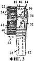
фиг.3 представляет вертикальный вид сбоку головки, показанной на фиг.1-2;figure 3 is a vertical side view of the head shown in figures 1-2;
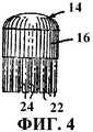
фиг.4 представляет вид сверху головки, показанной на фиг.1-3.figure 4 is a top view of the head shown in figures 1-3.
На фиг.1-4 проиллюстрирован один вариант осуществления данного изобретения, в котором зубная щетка 10 имеет суженную часть 12 ручки 30, которая показана частично, и включает головку 14. Головка 14 может представлять собой сменную, то есть вновь наполняемую головку, или головка 14 может быть постоянно прикреплена к ручке 30 в варианте осуществления данного изобретения.Figures 1-4 illustrate one embodiment of the present invention in which the
Как проиллюстрировано, в частности на фиг.2, головка 14 включает первый блок 16 с пучками щетинок, который проиллюстрирован как находящийся в самой наружной или дальней части головки 14. Блок 16 предпочтительно представляет собой диск круглой кольцевой формы, имеющий открытую внутреннюю зону. Блок 16 приспособлен для совершения колебаний вращательным образом, как показано стрелкой 17. При желании могут быть использованы другие формы этого блока, такие как яйцевидная форма или овальная форма, или различные правильные или неправильные формы при условии, что (в предпочтительном варианте осуществления изобретения) существует открытая зона, в которой может быть установлен второй блок 18 с пучками щетинок. Яйцевидная форма или круглая форма блока 16 является предпочтительной, при этом круглая форма является наиболее предпочтительной, поскольку такая форма требует наименьшей величины зазора для обеспечения возможности колебательного движения и для размещения внутреннего второго блока 18.As illustrated in particular in FIG. 2, the
Блок 18 предпочтительно представляет собой диск с круглым поперечным сечением, который также предназначен для совершения колебаний вращательным образом, как показано стрелкой 20. Таким образом, первый блок 16 и второй блок 18 установлены концентрично относительно друг друга на дальнем конце головки 14.The
Первый блок 16 включает множество пучков щетинок 22. В проиллюстрированном варианте осуществления пучки щетинок 22 выполнены в виде концентричного дугообразного ряда. Аналогичным образом, блок 18 выполнен с множеством пучков щетинок 24, которые также могут располагаться по концентричной дуге относительно друг друга вдоль окружности, параллельной дугообразному ряду щетинок 22.The
Две группы щетинок 22, 24, расположенных в виде концентричных дуг, предпочтительны, поскольку такое расположение обеспечивает максимальную плотность щетинок на площади поверхности блоков 16, 18 и, если диаметр блока 18 будет достаточным, дополнительные щетинки могут быть размещены центрально в нем. В предпочтительном варианте осуществления изобретения щетинки 22 из наружного ряда выступают наружу от открытой для воздействия наружной поверхности 26 головки 14 на большее расстояние по сравнению со щетинками 24 из внутреннего дугообразного ряда. В результате создается чашеобразная конструкция, которая способствует удерживанию зубной пасты на щетинках 22, 24, как показано на фиг.4. Как показано на фиг.2, щетинки 22 из наружного ряда проходят, по существу, перпендикулярно блоку 16, тем не менее, щетинки 22 из наружного ряда могут быть наклонены наружу от блока 16 под острым углом относительно него.Two groups of
Блоки 16 и 18 могут быть приведены в колебательное движение с помощью любого пригодного приводного средства. Например, на фиг.3 проиллюстрирован приводной механизм такого типа, как описанный в патенте США № 5146942, все детали которого включены в данную заявку путем ссылки. Как показано в данном патенте, приводной вал 28 приводится во вращение приводным электродвигателем (непоказанным) в ручке 30 (см. фиг.2 патента). Электродвигатель может снабжаться энергией любым пригодным образом, например с помощью аккумуляторных батарей. Как показано на фиг.3, передающий стержень 32 соединен в рабочем положении, например, с помощью постоянного или разъединяемого соединения с приводным валом 28. Стержень 32 имеет V-образный участок, ориентированный перпендикулярно к оси вращения приводного вала 28 и эксцентрически по отношению к оси вращения. Первый наклонный участок 34 стержня входит в аксиальный паз в первом блоке 16. Второй дальний участок 36 стержня входит в аксиальный паз во втором блоке 18. Вращение вала 28 и стержня 32 приводит к вращению участков 34, 36. Поскольку эксцентрические части участков 34, 36 стержня установлены в пазах в блоках 16, 18, вращение передается блокам в виде колебательного вращательного движения, показанного стрелками 17 и 20 на фиг.2. Приводимый в движение с помощью стержня 32 первый блок 16 будет вращаться в направлении, противоположном направлению вращения второго блока 18.
В предпочтительном варианте осуществления данного изобретения колеблющиеся в противоположных направлениях ("в противофазе") первый и второй блоки установлены концентрично друг другу, как проиллюстрировано. Тем не менее, следует понимать, что изобретение также может иметь вариант осуществления, в котором первый и второй блоки будут расположены по-другому, например, будут расположены бок о бок или в продольном, или в поперечном направлении относительно продольной оси головки 14 и суженной части 12. Установка блоков с пучками щетинок концентрично относительно друг друга является предпочтительной, поскольку она обеспечивает возможность использования более простой конструкции привода, подобной проиллюстрированной на фиг.3, при одновременном сведении к минимуму занимаемого пространства. Тем не менее, изобретение может иметь вариант осуществления, в котором, например, первый блок 16 имеет цельную или закрытую круглую форму, а не кольцеобразную форму, и установлен в продольном направлении рядом со вторым блоком 18. Колебание в противоположных направлениях по-прежнему может быть обеспечено за счет разнесения участков 34 и 36 стержня 32 на большее расстояние друг от друга. В альтернативном варианте блоки 16, 18 могут быть расположены бок о бок и могут приводиться в действие отдельными приводными механизмами, имеющими, например, отдельные валы. Такие отдельные приводные механизмы также могут быть использованы в том случае, когда первый блок 16 и второй блок 18 установлены концентрично относительно друг друга. Отдельные приводные устройства не являются столь предпочтительными, поскольку они требуют использования дополнительных компонентов и занимаемого пространства.In a preferred embodiment of the present invention, the first and second blocks oscillating in opposite directions ("in antiphase") are mounted concentrically to each other, as illustrated. However, it should be understood that the invention may also have an embodiment in which the first and second blocks will be located differently, for example, will be located side by side or in the longitudinal or transverse direction relative to the longitudinal axis of the
Отличительным признаком изобретения является наличие третьего блока 38 с пучками щетинок, который проиллюстрирован как расположенный между суженной частью 12 и совершающими колебательное движение в противоположных направлениях блоками 16, 18. Тем не менее, следует понимать, что третий блок может быть расположен удаленно от блоков, колеблющихся в противоположных направлениях, или в поперечном направлении рядом с блоками, колеблющимися в противоположных направлениях, или между блоками, колеблющимися в противоположных направлениях, например, при выполнении третьего блока в виде отдельной концентричной дугообразной части внутри второго блока 18 за счет придания второму блоку 18 кольцеобразной формы. Тем не менее, предпочтительно, чтобы третий блок 38 был расположен в продольном направлении снаружи (за пределами) блоков, колеблющихся в противоположном направлении, с тем чтобы увеличить длину поверхностной зоны в головке 14, имеющей щетинки.A distinctive feature of the invention is the presence of a
Выполнение трех блоков с пучками щетинок также предпочтительно вследствие того, что зубная щетка с приводом имитирует по внешнему виду головки конструкцию обычной ручной зубной щетки, что делает зубную щетку с приводом или электрическую зубную щетку более приемлемой для пользователей, поскольку внешний вид имитирует то, что пользователь привык видеть. Кроме того, три части повышают эффективность зубной щетки как за счет перемещения блоков, так и за счет способности легко удерживать зубную пасту.The implementation of the three blocks with tufts of bristles is also preferable due to the fact that the toothbrush with a drive simulates the appearance of the head of a conventional manual toothbrush, which makes a toothbrush with a drive or an electric toothbrush more acceptable for users, because the appearance imitates what the user used to see. In addition, three parts increase the effectiveness of the toothbrush due to both the movement of the blocks and the ability to easily hold toothpaste.
Как проиллюстрировано на фиг.1-3, третий блок 38 также выполнен со щетинками 40, которые проходят наружу от наружной поверхности 26 третьего блока 38. Наружная поверхность 26 третьего блока 38 и наружная поверхность 26 внутреннего и наружного блоков 16, 18, колеблющихся в противоположных направлениях, предпочтительно являются копланарными относительно друг друга, так что наружная поверхность всей головки находится в одной плоскости. Тем не менее, изобретение может иметь вариант осуществления, в котором третий блок 38 содержит чередующиеся ряды одинаковой высоты или в котором щетинки некоторых или всех рядов выступают наружу на расстояние, отличающееся от расстояния, на которое выступают щетинки из других рядов, что приводит к различным уступам на наружной поверхности третьего блока 38.As illustrated in figures 1-3, the
В проиллюстрированном варианте осуществления, лучше всего показанном на фиг.3, по меньшей мере, некоторые из щетинок 40 выступают наружу от наружной поверхности 26 головки 14 на такое же расстояние, что и щетинки 22, с тем чтобы создать, по существу, плоскую поверхность для приема зубной пасты. Тем не менее, некоторые из щетинок 41 могут также быть более короткими, как проиллюстрировано на фиг.3.In the illustrated embodiment, best shown in FIG. 3, at least some of the
Несмотря на то что на фиг.1-4 проиллюстрированы щетинки, имеющие вид обычных волокон, подразумевается, что термин "щетинки" используется в общем смысле для обозначения чистящих элементов или массажных элементов и может охватывать, например, эластомерные пальцеобразные элементы или стенки, выполненные с круглой формой поперечного сечения или с заданной формой любого вида, включая прямолинейные участки или синусоидальные участки.Although FIGS. 1-4 illustrate bristles having the appearance of conventional fibers, it is understood that the term “bristles” is used in a general sense to mean cleaning elements or massage elements and may include, for example, elastomeric finger-shaped elements or walls made with a circular cross-sectional shape or with a given shape of any kind, including straight sections or sinusoidal sections.
Щетинки могут быть прикреплены к блокам или частям за счет пропускания их через соответствующие отверстия в блоке, так что основание щетинок будет установлено внутри или ниже блока. При желании щетинки могут быть заделаны в эластомерный материал, который дает возможность щетинкам совершать независимое движение в дополнение к движению, сообщаемому колеблющимися блоками 16 и 18, вместо того чтобы представлять собой неподвижные щетинки на неподвижном третьем блоке 38. Таким образом, подобные различные виды щетинок могут быть использованы для упомянутых щетинок или щетинок на любом из блоков головки 14.The bristles can be attached to the blocks or parts by passing them through the corresponding holes in the block, so that the base of the bristles will be installed inside or below the block. If desired, the bristles can be embedded in an elastomeric material that allows the bristles to make independent movement in addition to the movement imparted by the oscillating blocks 16 and 18, instead of being fixed bristles on the fixed
Следует понимать, что конкретная иллюстрация щетинок приведена только для примера. Тем не менее, изобретение может иметь варианты осуществления с различными комбинациями одинаковых или разных конфигураций щетинок, прикрепленных к головке известными способами, включая применение скоб или технологию образования пучков с заделыванием щетинок при формовании и т.д., и/или технологию с использованием одинаковых или разных материалов щетинок (таких как нейлоновые щетинки, спиральные щетинки, резиновые щетинки и т.д.). Как было указано выше, несмотря на то что на фиг.1-4 щетинки проиллюстрированы как, по существу, перпендикулярные к наружной поверхности головки 14, некоторые или все щетинки могут быть наклонены под разными углами относительно наружной поверхности головки с щетинками. Таким образом, существует возможность выбора комбинации конфигураций щетинок, материалов щетинок и ориентации щетинок для достижения определенных заданных результатов, например, таких как создание ситуации, при которой колеблющиеся головки с пучками совершают как можно больше движений для обеспечения дополнительных преимуществ с точки зрения гигиены ротовой полости, подобных улучшенной очистке, полированию зубов, отбеливанию зубов и/или массажу десен.It should be understood that a specific illustration of the bristles is for example only. However, the invention may have embodiments with different combinations of the same or different configurations of the bristles attached to the head by known methods, including the use of staples or bundle technology with closing the bristles during molding, etc., and / or technology using the same or different bristle materials (such as nylon bristles, spiral bristles, rubber bristles, etc.). As indicated above, although in FIGS. 1-4, the bristles are illustrated as being substantially perpendicular to the outer surface of the
Следует понимать, что изобретение может быть реализовано на практике путем размещения пучков щетинок в любой другой открытой зоне головки зубной щетки. Такие пучки щетинок могут представлять собой неподвижные щетинки, установленные перпендикулярно или установленные под углом к открытой для воздействия наружной поверхности 26 головки 14, или могут представлять собой щетинки, установленные на эластомерной основе, с тем чтобы обеспечить возможность их независимого перемещения при приложении давления. Такие щетинки в их нормальном состоянии могут или быть перпендикулярными, или располагаться под углом к открытой для воздействия наружной поверхности головки зубной щетки.It should be understood that the invention can be practiced by placing tufts of bristles in any other open area of the head of the toothbrush. Such tufts of bristles may be fixed bristles mounted perpendicularly or set at an angle to the exposed
Изобретение также может иметь варианты осуществления, в которых различные группы щетинок имеют разные цвета. Таким образом, например, дугообразный ряд щетинок 22 может иметь белый цвет, в то время как внутренний ряд щетинок 24 может иметь синий цвет. Замкнутый дугообразный ряд из 8 пучков щетинок 40 на участке неподвижного блока 38, расположенном рядом с суженной частью 12, и пучок щетинок, находящийся внутри этого дугообразного ряда, также может иметь синий цвет, в то время как следующий дугообразный ряд из пяти пучков щетинок 41 может иметь белый цвет или иметь более короткие щетинки по сравнению с остальными щетинками неподвижного блока 38. Последние семь пучков щетинок 40, расположенные рядом с колеблющимися в противоположных направлениях щетинками, могут иметь зеленый цвет. Следует понимать, что представленное выше описание определенных комбинаций цветов приведено просто для примера, и может быть использована любая комбинация цветов, включая только один цвет.The invention may also have embodiments in which different groups of bristles have different colors. Thus, for example, the arched row of
Предпочтительно неподвижный блок 38 представляет собой конструкцию седлообразного типа, предназначенную для фиксации на головке 14 любым пригодным образом. В результате существует возможность замены одной неподвижной части, имеющей щетинки одного типа, другой неподвижной частью, имеющей щетинки других типов.Preferably, the fixed
Предпочтительно изобретение реализуется в виде варианта осуществления, в котором третий блок 38 представляет собой неподвижную часть, имеющую или неподвижные щетинки, или щетинки, которые могут смещаться независимо друг от друга за счет того, что они установлены на эластомерной основе. Тем не менее, изобретение также может иметь вариант осуществления, в котором третий блок 38 также является подвижным. Например, третий блок 38 может перемещаться внутрь и наружу в направлении, по существу, перпендикулярном наружной поверхности 26 головки 14. Это приведет к образованию вибрирующей части. Для осуществления этого вибрационного перемещения (колебательного движения) внутрь и наружу может быть использован любой пригодный приводной механизм, такой как приводная часть такого типа, как описанная в патенте США № Re 35941, все детали которого включены в данную заявку путем ссылки. В альтернативном варианте вибрирующая часть может быть свободно "плавающей" без привода, обеспечивающего принудительное смещение. Результирующее движение внутрь и наружу показано стрелкой 42 на фиг.3. Могут быть предусмотрены другие виды движения третьего блока 38, подобные показанному стрелкой 44 на фиг.2, где движение показано как продольное по отношению к продольной оси головки 14, или движение может быть поперечным, подобным показанному стрелкой 46 на фиг.2. Любой пригодный приводной механизм может быть использован для выполнения этих движений, которые будут совершаться в плоскости, по существу, параллельной наружной поверхности 26 головки 14. Ссылаемся на одновременно рассматриваемую заявку 10/066459, поданную 31января 2002, все детали которой включены в данную заявку путем ссылки.Preferably, the invention is implemented as an embodiment, in which the
Как очевидно, изобретение тем самым включает первый блок с пучками щетинок и второй блок с пучками щетинок, которые установлены с возможностью совершения колебаний в противоположных направлениях по отношению друг к другу в плоскости, по существу, параллельной наружной поверхности головки. Кроме того, головка зубной щетки включает третий блок с пучками щетинок. Третий блок может представлять собой неподвижную часть, имеющую неподвижные щетинки или щетинки, выполненные с возможностью независимого перемещения за счет того, что они установлены на эластомерном основании. В альтернативном варианте третий блок также может перемещаться или вбок, в поперечном направлении, или внутрь и наружу. Щетинки на различных блоках могут иметь любые из конструкций, описанных выше, и могут иметь различную длину, различные цвета и жесткость, и могут быть установлены перпендикулярно или под углом к наружной поверхности головки.As is obvious, the invention thereby includes a first block with tufts of bristles and a second block with tufts of bristles that are mounted so that they can oscillate in opposite directions with respect to each other in a plane substantially parallel to the outer surface of the head. In addition, the head of the toothbrush includes a third block with tufts of bristles. The third block may be a fixed part having fixed bristles or bristles made with the possibility of independent movement due to the fact that they are mounted on an elastomeric base. Alternatively, the third block can also be moved either sideways, in the transverse direction, or in and out. The bristles on the various blocks can have any of the designs described above, and can have different lengths, different colors and stiffness, and can be installed perpendicular or at an angle to the outer surface of the head.
Claims (12)
Translated fromRussianApplications Claiming Priority (2)
| Application Number | Priority Date | Filing Date | Title |
|---|---|---|---|
| US10/107,092 | 2002-03-26 | ||
| US10/107,092US7552497B2 (en) | 2002-03-26 | 2002-03-26 | Powered toothbrush with rotating sections |
Publications (2)
| Publication Number | Publication Date |
|---|---|
| RU2004131553A RU2004131553A (en) | 2005-04-20 |
| RU2312637C2true RU2312637C2 (en) | 2007-12-20 |
Family
ID=28452595
Family Applications (1)
| Application Number | Title | Priority Date | Filing Date |
|---|---|---|---|
| RU2004131553/12ARU2312637C2 (en) | 2002-03-26 | 2003-03-25 | Toothbrush with drive and rotating parts |
Country Status (13)
| Country | Link |
|---|---|
| US (4) | US7552497B2 (en) |
| EP (2) | EP2609832B1 (en) |
| KR (1) | KR100996765B1 (en) |
| CN (1) | CN100506111C (en) |
| AU (1) | AU2003215030B2 (en) |
| BR (1) | BR0308735B1 (en) |
| CA (1) | CA2479945C (en) |
| ES (1) | ES2523866T3 (en) |
| MX (1) | MXPA04009280A (en) |
| NO (1) | NO20044589L (en) |
| PL (1) | PL372379A1 (en) |
| RU (1) | RU2312637C2 (en) |
| WO (1) | WO2003082049A1 (en) |
Cited By (2)
| Publication number | Priority date | Publication date | Assignee | Title |
|---|---|---|---|---|
| RU2411892C1 (en)* | 2010-04-07 | 2011-02-20 | Олег Николаевич Моисеев | Toothbrush mon with electric drive |
| RU2574361C2 (en)* | 2010-06-22 | 2016-02-10 | Конинклейке Филипс Электроникс Н.В. | Mouthpiece for cleaning teeth with mechanical drive |
Families Citing this family (80)
| Publication number | Priority date | Publication date | Assignee | Title |
|---|---|---|---|---|
| US7743448B2 (en)* | 1999-06-11 | 2010-06-29 | Gavney Jr James A | Device and system with moving squeegee fields |
| US6574820B1 (en) | 1999-10-22 | 2003-06-10 | The Gillette Company | Brush head for toothbrush |
| US6920659B2 (en) | 2001-01-12 | 2005-07-26 | Water Pik, Inc. | Toothbrush |
| US6955539B2 (en) | 2001-07-12 | 2005-10-18 | Water Pik, Inc. | Characterization of motion of dual motor oral hygiene device |
| US20030084525A1 (en) | 2001-11-07 | 2003-05-08 | The Procter & Gamble Company | Complex motion toothbrush |
| US7640614B2 (en) | 2001-11-06 | 2010-01-05 | The Procter & Gamble Company | Multi motion toothbrush |
| AU2003280410B8 (en)* | 2002-01-18 | 2009-04-23 | Zymogenetics, Inc. | Cytokine receptor zcytor17 multimers |
| US20030140437A1 (en)* | 2002-01-31 | 2003-07-31 | Eyal Eliav | Powered toothbrush |
| US6892412B2 (en)* | 2002-01-31 | 2005-05-17 | Colgate-Palmolive Company | Powered toothbrush |
| US20030163882A1 (en) | 2002-03-04 | 2003-09-04 | The Procter & Gamble Company | Electric toothbrushes |
| US7269872B2 (en)* | 2002-04-12 | 2007-09-18 | Colgate-Palmolive Company | Powered toothbrush head |
| US20030196283A1 (en)* | 2002-04-23 | 2003-10-23 | Eyal Eliav | Powered toothbrush |
| US20030226223A1 (en) | 2002-06-11 | 2003-12-11 | The Procter & Gamble Co. | High efficiency electric toothbrush |
| US7636976B2 (en) | 2002-12-30 | 2009-12-29 | The Procter & Gamble Company | Power toothbrush |
| US7934284B2 (en) | 2003-02-11 | 2011-05-03 | Braun Gmbh | Toothbrushes |
| USD612611S1 (en) | 2003-02-11 | 2010-03-30 | The Gillette Company | Head of a toothbrush |
| WO2004093719A2 (en) | 2003-04-23 | 2004-11-04 | The Procter & Gamble Company | Electric toothbrushes |
| US7302726B2 (en) | 2003-05-23 | 2007-12-04 | Braun Gmbh | Toothbrushes |
| DE60326286D1 (en)* | 2003-12-10 | 2009-04-02 | Church & Dwight Co Inc | MODULAR ELECTRIC TOOTHBRUSHES |
| US7698771B2 (en)* | 2003-12-19 | 2010-04-20 | The Procter & Gamble Company | Electric toothbrush |
| US7861348B2 (en) | 2004-12-08 | 2011-01-04 | The Procter & Gamble Company | Electric toothbrushes |
| US8668618B2 (en) | 2008-10-12 | 2014-03-11 | Christopher C. Sappenfield | Rotary units, rotary mechanisms, and related applications |
| US9312740B2 (en) | 2008-10-12 | 2016-04-12 | Christopher C. Sappenfield | Apparatus comprising counter-rotational mechanisms and related methods to convey current |
| US8684883B2 (en) | 2008-10-12 | 2014-04-01 | Christopher C. Sappenfield | Handheld devices and related methods |
| US8668619B2 (en) | 2008-10-12 | 2014-03-11 | Christopher C. Sappenfield | Rotary units, rotary mechanisms, and related applications |
| US8672798B2 (en) | 2008-10-12 | 2014-03-18 | Christopher C. Sappenfield | Rotary units, rotary mechanisms, and related applications |
| US8672799B2 (en)* | 2008-10-12 | 2014-03-18 | Christopher C. Sappenfield | Rotary units, rotary mechanisms, and related applications |
| US8715133B2 (en) | 2008-10-12 | 2014-05-06 | Christopher C. Sappenfield | Rotary units, rotary mechanisms, and related applications |
| US8834315B2 (en) | 2008-10-12 | 2014-09-16 | Christopher C. Sappenfield | Rotary units, rotary mechanisms, and related applications |
| US9382973B2 (en) | 2008-10-12 | 2016-07-05 | Christopher C. Sappenfield | Rotary units, rotary mechanisms, and related applications |
| US20110067190A1 (en)* | 2009-09-17 | 2011-03-24 | Brattesani Steven J | Tooth shade indicator apparatus and method for evaluating tooth shade |
| EP2410641A1 (en) | 2010-07-23 | 2012-01-25 | Braun GmbH | Linear electric motor |
| EP2420203B1 (en) | 2010-08-19 | 2019-10-23 | Braun GmbH | Resonant motor unit and electric device with resonant motor unit |
| USD703443S1 (en)* | 2010-12-20 | 2014-04-29 | Colgate-Palmolive Company | Oral care implement accessory |
| USD711655S1 (en)* | 2010-12-20 | 2014-08-26 | Colgate-Palmolive Company | Oral care implement accessory |
| USD690515S1 (en) | 2010-12-20 | 2013-10-01 | Colgate-Palmolive Company | Oral care implement accessory |
| KR101571951B1 (en) | 2011-05-02 | 2015-11-25 | 워터 피크 인코포레이티드 | Mechanically-driven, sonic toothbrush |
| CA2840474A1 (en)* | 2011-07-06 | 2013-01-10 | Braun Gmbh | Cleaning section for an electric oral hygiene device |
| RU2014104790A (en)* | 2011-07-12 | 2015-08-20 | Колгейт-Палмолив Компани | DENTAL BRUSH AND REPLACEMENT HEAD FOR DENTAL BRUSH |
| AU2012283146B2 (en)* | 2011-07-12 | 2014-11-27 | Colgate-Palmolive Company | Toothbrush and refill head for the same |
| RU2014104809A (en)* | 2011-07-12 | 2015-08-20 | Колгейт-Палмолив Компани | DENTAL BRUSH AND REPLACEMENT HEAD FOR DENTAL BRUSH |
| PH12013502607A1 (en)* | 2011-07-12 | 2019-03-22 | Colgate Palmolive Co | Refill head for an oral care implement handle |
| WO2013009360A1 (en)* | 2011-07-12 | 2013-01-17 | Colgate-Palmolive Company | Vibratory and oscillatory toothbrush and refill head for the same |
| MX2014000423A (en)* | 2011-07-12 | 2014-02-27 | Colgate Palmolive Co | TEETH BRUSH AND SPARE HEAD FOR THE SAME. |
| CN103703668B (en) | 2011-07-25 | 2016-12-07 | 博朗有限公司 | Linear electro-polymer motor and the device with described linear electro-polymer motor |
| ES2451021T3 (en) | 2011-07-25 | 2014-03-26 | Braun Gmbh | Magnetic connection between a toothbrush handle and a brush head |
| PL2550938T3 (en) | 2011-07-25 | 2015-06-30 | Braun Gmbh | Oral hygiene device |
| USD676661S1 (en) | 2011-08-23 | 2013-02-26 | Colgate-Palmolive Company | Oral care implement accessory |
| USD676662S1 (en) | 2011-08-23 | 2013-02-26 | Colgate-Palmolive Company | Oral care implement accessory |
| FR2992856B1 (en)* | 2012-07-09 | 2016-02-19 | Oreal | DEVICE FOR MASSAGE AND APPLICATION OF A COSMETIC COMPOSITION |
| US9131765B2 (en)* | 2012-12-20 | 2015-09-15 | Brushpoint Innovations Inc | Brush head for an electric toothbrush |
| CN104994766B (en) | 2013-03-15 | 2017-10-03 | 洁碧有限公司 | Mechanically powered sonic toothbrush and water flosser |
| US9468511B2 (en) | 2013-03-15 | 2016-10-18 | Water Pik, Inc. | Electronic toothbrush with vibration dampening |
| USD769626S1 (en) | 2013-12-19 | 2016-10-25 | Colgate-Palmolive Company | Refill head for electric toothbrush |
| USD776435S1 (en) | 2013-12-19 | 2017-01-17 | Colgate-Palmolive Company | Head portion of a toothbrush |
| USD766581S1 (en) | 2013-12-19 | 2016-09-20 | Colgate-Palmolive Company | Electric toothbrush handle |
| CN104720912B (en)* | 2013-12-19 | 2017-04-12 | 高露洁-棕榄公司 | Electric toothbrush head with combined swing motion hair group block |
| US9333059B2 (en)* | 2014-02-04 | 2016-05-10 | Stevi Llc | Multi-function electric brush apparatus and systems useful for cleaning teeth and interdental spaces |
| US9504543B1 (en) | 2014-11-14 | 2016-11-29 | Paul Hammond Martin | Electric toothbrush with continuous rotating brush and vibrating section |
| USD780457S1 (en)* | 2014-12-23 | 2017-03-07 | Colgate-Palmolive Company | Oral care implement |
| US10849727B2 (en) | 2015-01-09 | 2020-12-01 | Church & Dwight Co., Inc. | Electric toothbrush |
| CN205568226U (en) | 2015-07-08 | 2016-09-14 | 洁碧有限公司 | Device of brushing teeth |
| CN105125309B (en)* | 2015-09-28 | 2016-11-30 | 陈浩骏 | A kind of method using electric toothbrush to brush teeth and toothbrush |
| US10206492B2 (en) | 2015-10-09 | 2019-02-19 | Stevi, Llc | Brushes useful for cleaning teeth and interdental spaces |
| USD794333S1 (en) | 2015-11-25 | 2017-08-15 | Colgate-Palmolive Company | Electric toothbrush brush head |
| USD790860S1 (en)* | 2015-11-25 | 2017-07-04 | Colgate-Palmolive Company | Electric toothbrush brush head |
| US20170265638A1 (en)* | 2016-03-18 | 2017-09-21 | Arslanbek Sagynaliev | Tooth brush apparatus and methods of use |
| US10561480B2 (en) | 2016-05-09 | 2020-02-18 | Water Pik, Inc. | Load sensing for oral devices |
| US10251472B1 (en) | 2016-05-23 | 2019-04-09 | Dana P. Hervig | Infinity brush |
| US10687925B2 (en)* | 2016-07-22 | 2020-06-23 | Braun Gmbh | Brush head and electric toothbrush |
| CN108078641B (en) | 2016-11-21 | 2021-05-28 | 高露洁-棕榄公司 | Oral care implement |
| USD846285S1 (en) | 2016-11-21 | 2019-04-23 | Colgate-Palmolive Company | Oral care implement |
| CN108078642B (en) | 2016-11-21 | 2021-02-09 | 高露洁-棕榄公司 | Oral care implement |
| USD845636S1 (en) | 2016-12-15 | 2019-04-16 | Water Pik, Inc. | Toothbrush handle |
| USD844997S1 (en) | 2016-12-15 | 2019-04-09 | Water Pik, Inc. | Toothbrush handle |
| WO2018112309A1 (en) | 2016-12-15 | 2018-06-21 | Water Pik, Inc. | Brushing device with illumination features |
| US10384655B2 (en)* | 2017-07-05 | 2019-08-20 | Istobal, S.A. | Head for washing vehicle wheels |
| US11596508B2 (en) | 2019-03-08 | 2023-03-07 | Church & Dwight Co., Inc. | Electric toothbrush and a brush head for the same |
| USD972302S1 (en) | 2020-03-13 | 2022-12-13 | Ranir, Llc | Toothbrush drive unit |
| WO2022235763A1 (en)* | 2021-05-04 | 2022-11-10 | Achieve Equine Llc | Grooming systems for a horse coat |
Citations (5)
| Publication number | Priority date | Publication date | Assignee | Title |
|---|---|---|---|---|
| US5524312A (en)* | 1995-03-06 | 1996-06-11 | Tan; Kuo-Ching | Electric toothbrush |
| US5836030A (en)* | 1995-12-28 | 1998-11-17 | U.S. Philips Corporation | Dental cleaning device and attachment for such a device |
| RU2141278C1 (en)* | 1994-10-29 | 1999-11-20 | БРАУН ГмбХ | Brush head for electric tooth brush |
| WO2001060281A1 (en)* | 2000-02-15 | 2001-08-23 | Glaxosmithkline Consumer Healthcare Gmbh & Co Kg | Brush part for an electric toothbrush |
| EP1132022A1 (en)* | 2000-03-07 | 2001-09-12 | Cliffield Industries Ltd. | Household appliance |
Family Cites Families (21)
| Publication number | Priority date | Publication date | Assignee | Title |
|---|---|---|---|---|
| US1796641A (en)* | 1928-03-29 | 1931-03-17 | Fred Foell | Spotting brush |
| IL92720A (en)* | 1989-12-15 | 1993-02-21 | Neta Holland | Toothbrush |
| US5146942A (en) | 1991-05-06 | 1992-09-15 | Taylor Julian S | Low pressure fluid emergency shutdown valve |
| DE4201873C1 (en)* | 1992-01-24 | 1993-05-27 | Braun Ag, 6000 Frankfurt, De | Brush for electrically operated toothbrush - has two concentric circular rings of bristles of different heights spaced apart by circle without bristles same width as circle with bristles |
| US5259083A (en)* | 1992-09-24 | 1993-11-09 | 1008335 Ontario Inc. | Mechanical toothbrush |
| DE4239251A1 (en)* | 1992-11-21 | 1994-05-26 | Braun Ag | Electric toothbrush with rotating bristle holder |
| IT1261901B (en)* | 1993-02-26 | 1996-06-03 | Ariete Srl | TOOTHBRUSH, ANTI-PLAQUE, MOTORIZED. |
| DE4309035C2 (en)* | 1993-03-20 | 1999-04-08 | Braun Ag | Electric toothbrush and brush part for an electric toothbrush |
| US5625916A (en)* | 1995-05-24 | 1997-05-06 | Mcdougall; Greg | Toothbrush |
| US6032313A (en)* | 1995-05-26 | 2000-03-07 | Tsang; Koon Keung | Household appliance having plural coaxially rotatable or parallel linearly movable heads or tools |
| DE19536720A1 (en) | 1995-09-30 | 1997-04-03 | Braun Ag | Brush part for an electric toothbrush |
| US5967617A (en)* | 1998-03-02 | 1999-10-19 | Zapanta; Gary | Filament tape for cleaning and dental application |
| US6178579B1 (en)* | 1998-09-30 | 2001-01-30 | Dr. Johns Products, Ltd. | Electric toothbrush |
| US6000083A (en)* | 1998-09-30 | 1999-12-14 | Dr. Johns Products, Ltd. | Electric toothbrush |
| EP1132057A1 (en) | 2000-03-06 | 2001-09-12 | Unilever N.V. | Toothbrush with segmented oscillating head |
| TWI286491B (en) | 2000-05-15 | 2007-09-11 | Ngk Insulators Ltd | Absorbents having the capability of decomposing organic halogen compounds and a process for producing the same |
| US6564416B1 (en)* | 2000-05-22 | 2003-05-20 | Gillette Canada Company | Toothbrush |
| US20030033679A1 (en)* | 2001-08-17 | 2003-02-20 | Joseph Fattori | Brush section for an electric toothbrush |
| US6725490B2 (en)* | 2001-11-06 | 2004-04-27 | The Procter & Gamble Company | Complex motion toothbrush |
| US20030163882A1 (en)* | 2002-03-04 | 2003-09-04 | The Procter & Gamble Company | Electric toothbrushes |
| US6889401B2 (en)* | 2002-03-26 | 2005-05-10 | Colgate-Palmolive Company | Powered toothbrush with vibrating section |
- 2002
- 2002-03-26USUS10/107,092patent/US7552497B2/ennot_activeExpired - Fee Related
- 2003
- 2003-03-25CNCNB038115530Apatent/CN100506111C/ennot_activeExpired - Fee Related
- 2003-03-25KRKR1020047015276Apatent/KR100996765B1/ennot_activeExpired - Fee Related
- 2003-03-25EPEP13152884.6Apatent/EP2609832B1/ennot_activeExpired - Lifetime
- 2003-03-25PLPL03372379Apatent/PL372379A1/ennot_activeApplication Discontinuation
- 2003-03-25EPEP03711675.3Apatent/EP1489941B1/ennot_activeExpired - Lifetime
- 2003-03-25MXMXPA04009280Apatent/MXPA04009280A/enactiveIP Right Grant
- 2003-03-25AUAU2003215030Apatent/AU2003215030B2/ennot_activeCeased
- 2003-03-25BRBRPI0308735-2Apatent/BR0308735B1/ennot_activeIP Right Cessation
- 2003-03-25CACA2479945Apatent/CA2479945C/ennot_activeExpired - Fee Related
- 2003-03-25ESES03711675.3Tpatent/ES2523866T3/ennot_activeExpired - Lifetime
- 2003-03-25RURU2004131553/12Apatent/RU2312637C2/ennot_activeIP Right Cessation
- 2003-03-25WOPCT/US2003/009116patent/WO2003082049A1/ennot_activeApplication Discontinuation
- 2004
- 2004-10-25NONO20044589Apatent/NO20044589L/ennot_activeApplication Discontinuation
- 2009
- 2009-05-27USUS12/472,807patent/US7954192B2/ennot_activeExpired - Fee Related
- 2011
- 2011-05-13USUS13/107,640patent/US8250694B2/ennot_activeExpired - Fee Related
- 2012
- 2012-08-08USUS13/569,846patent/US8713738B2/ennot_activeExpired - Fee Related
Patent Citations (5)
| Publication number | Priority date | Publication date | Assignee | Title |
|---|---|---|---|---|
| RU2141278C1 (en)* | 1994-10-29 | 1999-11-20 | БРАУН ГмбХ | Brush head for electric tooth brush |
| US5524312A (en)* | 1995-03-06 | 1996-06-11 | Tan; Kuo-Ching | Electric toothbrush |
| US5836030A (en)* | 1995-12-28 | 1998-11-17 | U.S. Philips Corporation | Dental cleaning device and attachment for such a device |
| WO2001060281A1 (en)* | 2000-02-15 | 2001-08-23 | Glaxosmithkline Consumer Healthcare Gmbh & Co Kg | Brush part for an electric toothbrush |
| EP1132022A1 (en)* | 2000-03-07 | 2001-09-12 | Cliffield Industries Ltd. | Household appliance |
Cited By (2)
| Publication number | Priority date | Publication date | Assignee | Title |
|---|---|---|---|---|
| RU2411892C1 (en)* | 2010-04-07 | 2011-02-20 | Олег Николаевич Моисеев | Toothbrush mon with electric drive |
| RU2574361C2 (en)* | 2010-06-22 | 2016-02-10 | Конинклейке Филипс Электроникс Н.В. | Mouthpiece for cleaning teeth with mechanical drive |
Also Published As
| Publication number | Publication date |
|---|---|
| ES2523866T3 (en) | 2014-12-02 |
| US20110283470A1 (en) | 2011-11-24 |
| NO20044589L (en) | 2004-12-23 |
| CA2479945A1 (en) | 2003-10-09 |
| AU2003215030B2 (en) | 2009-04-09 |
| MXPA04009280A (en) | 2005-01-25 |
| RU2004131553A (en) | 2005-04-20 |
| EP2609832A2 (en) | 2013-07-03 |
| KR100996765B1 (en) | 2010-11-25 |
| US8713738B2 (en) | 2014-05-06 |
| US7954192B2 (en) | 2011-06-07 |
| US8250694B2 (en) | 2012-08-28 |
| PL372379A1 (en) | 2005-07-25 |
| CN100506111C (en) | 2009-07-01 |
| WO2003082049A1 (en) | 2003-10-09 |
| US20030182743A1 (en) | 2003-10-02 |
| US20130031733A1 (en) | 2013-02-07 |
| CN1655703A (en) | 2005-08-17 |
| KR20040094869A (en) | 2004-11-10 |
| BR0308735A (en) | 2005-01-11 |
| BR0308735B1 (en) | 2013-02-19 |
| US7552497B2 (en) | 2009-06-30 |
| CA2479945C (en) | 2012-08-07 |
| EP1489941B1 (en) | 2014-09-17 |
| EP1489941A1 (en) | 2004-12-29 |
| AU2003215030A1 (en) | 2003-10-13 |
| EP2609832A3 (en) | 2014-04-02 |
| EP2609832B1 (en) | 2017-10-04 |
| US20090313774A1 (en) | 2009-12-24 |
Similar Documents
| Publication | Publication Date | Title |
|---|---|---|
| RU2312637C2 (en) | Toothbrush with drive and rotating parts | |
| RU2299042C2 (en) | Tooth-brush with drive unit | |
| US6889401B2 (en) | Powered toothbrush with vibrating section | |
| US7900309B2 (en) | Powered toothbrush | |
| KR20040101443A (en) | Powered toothbrush head | |
| HK1184346A (en) | Powered toothbrush with rotating sections | |
| HK1183778A (en) | Powered toothbrush |
Legal Events
| Date | Code | Title | Description |
|---|---|---|---|
| MM4A | The patent is invalid due to non-payment of fees | Effective date:20180326 |