RU2310271C1 - Current-to-pulse-frequency converter - Google Patents
Current-to-pulse-frequency converterDownload PDFInfo
- Publication number
- RU2310271C1 RU2310271C1RU2006116128/28ARU2006116128ARU2310271C1RU 2310271 C1RU2310271 C1RU 2310271C1RU 2006116128/28 ARU2006116128/28 ARU 2006116128/28ARU 2006116128 ARU2006116128 ARU 2006116128ARU 2310271 C1RU2310271 C1RU 2310271C1
- Authority
- RU
- Russia
- Prior art keywords
- threshold element
- input
- current
- output
- converter
- Prior art date
Links
- 239000003990capacitorSubstances0.000claimsabstractdescription23
- 238000006243chemical reactionMethods0.000abstractdescription5
- 238000005259measurementMethods0.000abstract2
- 238000012905input functionMethods0.000abstract1
- 239000000126substanceSubstances0.000abstract1
- 238000010586diagramMethods0.000description3
- 230000007423decreaseEffects0.000description1
- 238000004870electrical engineeringMethods0.000description1
Images
Landscapes
- Measurement Of Current Or Voltage (AREA)
Abstract
Description
Translated fromRussianИзобретение относится к электроизмерительной технике и может быть использовано при измерении тока.The invention relates to electrical engineering and can be used in measuring current.
Известен преобразователь тока в частоту импульсов (а.с. СССР № 1211660, пр. 10.04.1984, кл. G01R 19/25), содержащий источник опорного напряжения, электронный коммутатор, интегрирующий конденсатор и блок управления, включающий пороговый элемент. Недостатком этого преобразователя является то, что интегрирующий конденсатор заряжается измеряемым током, а разряжается током, равным разности разрядного и измеряемого токов, чем обусловлена погрешность преобразования.A known current to pulse frequency converter (AS USSR No. 1211660, pr. 10.04.1984, class G01R 19/25), comprising a reference voltage source, an electronic switch, an integrating capacitor and a control unit including a threshold element. The disadvantage of this converter is that the integrating capacitor is charged with a measured current, and discharged with a current equal to the difference between the discharge and measured currents, which causes the conversion error.
Задачей, на решение которой направлено заявляемое изобретение, является повышение точности преобразования.The problem to which the invention is directed, is to increase the accuracy of conversion.
Поставленная задача решается тем, что в преобразователе тока в частоту импульсов, содержащем источник опорного напряжения, выход которого соединен с одним входом электронного коммутатора, интегрирующий конденсатор, пороговый элемент, электронный коммутатор выполнен из четырех электронных ключей, соединенных по схеме моста, в диагональ которого подключены интегрирующий конденсатор и входы порогового элемента, прямой и инверсный выходы которого соединены с управляющими входами электронного коммутатора, другой вход которого является входом преобразователя, а прямой выход порогового элемента является выходом преобразователя.The problem is solved in that in the current transducer into a frequency of pulses containing a reference voltage source, the output of which is connected to one input of the electronic switch, an integrating capacitor, a threshold element, the electronic switch is made of four electronic keys connected by a bridge circuit, the diagonal of which is connected an integrating capacitor and inputs of the threshold element, the direct and inverse outputs of which are connected to the control inputs of the electronic switch, the other input of which is stroke transducer and a direct output of the threshold element is the output transducer.
При использовании предлагаемого преобразователя конденсатор заряжается и разряжается измеряемым током, чем достигается повышение точности преобразования.When using the proposed converter, the capacitor is charged and discharged by the measured current, thereby achieving improved conversion accuracy.
На фиг.1 представлена схема преобразователя тока в частоту импульсов;Figure 1 presents a diagram of a converter of current into a pulse frequency;
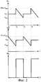
на фиг.2 - эпюры напряжений в предлагаемом преобразователе.figure 2 - plot voltage in the proposed Converter.
Преобразователь тока в частоту импульсов (фиг.1) содержит электронный коммутатор 1, включающий четыре электронных ключа 2, 3, 4, 5, соединенных по схеме моста. К первой стороне моста подключен источник 6 опорного напряжения, вторая сторона моста является входом преобразователя для подключения к источнику тока, в диагональ моста включен интегрирующий конденсатор 7. Параллельно интегрирующему конденсатору 7 подключены первый и второй входы порогового элемента 8, прямой и инверсный выходы которого соединены с управляющими входами электронных ключей 2-5. При этом прямой выход порогового элемента 8 является выходом преобразователя.The current to pulse frequency converter (FIG. 1) contains an electronic switch 1, including four electronic keys 2, 3, 4, 5, connected by a bridge circuit. A reference voltage source 6 is connected to the first side of the bridge, the second side of the bridge is an input of the converter for connecting to a current source, an integrating capacitor 7 is included in the diagonal of the bridge. Parallel to the integrating capacitor 7, the first and second inputs of the threshold element 8 are connected, the direct and inverse outputs of which are connected to control inputs of electronic keys 2-5. In this case, the direct output of the threshold element 8 is the output of the Converter.
Пороговый элемент 8 может быть выполнен в виде RS-триггера, R- и S-входы которого обладают высоким входным сопротивлением, а также гистерезисом, характерным для триггера Шмитта. На фиг.1 приведена схема возможной реализации порогового элемента 8 на КМОП-микросхеме типа К561ТЛ1. Электронные ключи 2-5 могут быть выполнены на КМОП-микросхеме типа К561КТ3.The threshold element 8 can be made in the form of an RS-trigger, the R- and S-inputs of which have a high input resistance, as well as the hysteresis characteristic of a Schmitt trigger. Figure 1 shows a diagram of a possible implementation of the threshold element 8 on a CMOS chip type K561TL1. Electronic keys 2-5 can be performed on a CMOS chip type K561KT3.
Предлагаемый преобразователь работает следующим образом.The proposed Converter operates as follows.
Пусть измеряемый ток I источника тока имеет отличную от нуля величину, постоянную во времени. В исходном состоянии в момент времени t0 (фиг.2) на прямом выходе порогового элемента 8 присутствует напряжение логического нуля, на инверсном выходе - логической единицы. Тогда электронные ключи 2, 5 находятся в закрытом состоянии, а электронные ключи 3, 4 - в открытом состоянии. Интегрирующий конденсатор 7 заряжается по цепи: источник 6 опорного напряжения, электронный ключ 4, интегрирующий конденсатор 7, электронный ключ 3, источник тока. Ток заряда конденсатора 7 равен измеряемому току I источника тока. Напряжение U1 на первом входе порогового элемента 8 равно напряжению источника 6 опорного напряжения Uоп, а напряжение U2 на втором входе порогового элемента 8 снижается по мере заряда интегрирующего конденсатора 7. В момент времени t1 напряжение U2 достигает уровня напряжения переключения порогового элемента 8 по второму входу Uпор2, пороговый элемент 8 переключается, и на его прямом выходе появляется напряжение логической единицы, а на инверсном выходе - логического нуля, электронные ключи 3, 4 закрываются, а электронные ключи 2, 5 открываются. Напряжение заряженного конденсатора 7, равное Uоп-Uпор2, суммируясь с напряжением источника 6 опорного напряжения, прикладывается к первому входу порогового элемента 8. В интервале времени t1-t2 ток I идет через конденсатор 7 в противоположном направлении, в отличие от интервала времени t0-t1, при этом напряжение U1 на первом входе порогового элемента 8 изменяется от 2Uоп-Uпор2 до напряжения переключения порогового элемента 8 по первому входу Uпор1. В момент времени t2 происходит переключение порогового элемента 8, напряжение заряженного конденсатора 7, равное Uоп-Uпор1, суммируясь с напряжением источника 6 опорного напряжения, прикладывается ко второму входу порогового элемента 8. В интервале времени t2-t3 ток I идет через конденсатор 7 в противоположном направлении, в отличие от интервала времени t1-t2, при этом напряжение U2 на втором входе порогового элемента 8 изменяется от 2Uоп-Uпор1 до Uпор2. Состояние преобразователя в момент времени t3 совпадает с состоянием преобразователя в момент времени t1, следовательно, период Т колебаний напряжения U3 на выходе преобразователя равен длительности временного интервала t1-t3. В интервале времени t1-t2 напряжение на конденсаторе 7 изменяется на величину 2Uоп-Uпор2-Uпор1. В интервале времени t1-t3 напряжение на конденсаторе 7 изменяется на ту же величину, следовательно, длительности временных интервалов t1-t2 и t2-t3 равновелики, то есть эпюра напряжения U3 имеет форму симметричного меандра. Период Т определяется током I по следующей формуле:Let the measured current I of the current source have a non-zero value that is constant in time. In the initial state at time t0 (figure 2) at the direct output of the threshold element 8 there is a logic zero voltage, at the inverse output is a logical unit. Then the electronic keys 2, 5 are in the closed state, and the electronic keys 3, 4 are in the open state. The integrating capacitor 7 is charged in a circuit: a reference voltage source 6, an electronic switch 4, an integrating capacitor 7, an electronic switch 3, a current source. The charge current of the capacitor 7 is equal to the measured current I of the current source. The voltage U1 at the first input of the threshold element 8 is equal to the voltage of the source 6 of the reference voltage Uop , and the voltage U2 at the second input of the threshold element 8 decreases as the integrating capacitor 7 is charged. At time t1, the voltage U2 reaches the switching voltage level of the threshold element 8 to a second input of UTh2, the threshold element 8 is switched and at its direct output voltage appears logical unit, and the inverse output - a logic zero, electronic switches 3, 4 are closed and the electronic key 2, 5 are opened . The voltage of the charged capacitor 7, equal to Uop -Upore2 , summing up with the voltage of the reference voltage source 6, is applied to the first input of the threshold element 8. In the time interval t1 -t2, the current I flows through the capacitor 7 in the opposite direction, in contrast to the interval time t0 -t1 , while the voltage U1 at the first input of the threshold element 8 varies from 2Uop -Up2 to the switching voltage of the threshold element 8 at the first input Upore1 . At time t2 , the switching of the threshold element 8 occurs, the voltage of the charged capacitor 7, equal to Uop -Upor1 , summing up with the voltage of the reference voltage source 6, is applied to the second input of the threshold element 8. In the time interval t2 -t3, the current I goes through the capacitor 7 in the opposite direction, in contrast to the time interval t1 -t2 , while the voltage U2 at the second input of the threshold element 8 varies from 2Uop -Upor1 to Upor2 . The state of the converter at time t3 coincides with the state of the converter at time t1 , therefore, the period T of voltage fluctuations U3 at the output of the converter is equal to the duration of the time interval t1 -t3 . In the time interval t1 -t2, the voltage across the capacitor 7 changes by 2Uop -Up2 -Upore1 . In the time interval t1 -t3, the voltage across the capacitor 7 changes by the same amount, therefore, the durations of the time intervals t1 -t2 and t2 -t3 are equal, that is, the voltage diagram U3 has the shape of a symmetrical meander. The period T is determined by the current I according to the following formula:

где С - емкость интегрирующего конденсатора 7.where C is the capacitance of the integrating capacitor 7.
Частота импульсов f на прямом и инверсном выходах порогового элемента 8 определяется выражением:The pulse frequency f at the direct and inverse outputs of the threshold element 8 is determined by the expression:

Таким образом, частота импульсов f прямо пропорциональна величине измеряемого тока I, при этом заряд и разряд интегрирующего конденсатора 7 осуществляется измеряемым током I путем изменения направления тока I, чем обеспечивается точность преобразования.Thus, the pulse frequency f is directly proportional to the magnitude of the measured current I, while the charge and discharge of the integrating capacitor 7 is carried out by the measured current I by changing the direction of the current I, which ensures the accuracy of the conversion.
Достоинством устройства является то, что выходное напряжение U3, при заданной величине измеряемого тока I, имеет форму симметричного меандра, несмотря на то, что обычно Uпор1≠Uпор2 вследствие разброса параметров элементов схемы.The advantage of the device is that the output voltage U3 , for a given value of the measured current I, has the shape of a symmetrical meander, despite the fact that usually Upor1 ≠ Upor2 due to the spread of the parameters of the circuit elements.
Claims (1)
Translated fromRussianPriority Applications (1)
| Application Number | Priority Date | Filing Date | Title |
|---|---|---|---|
| RU2006116128/28ARU2310271C1 (en) | 2006-05-10 | 2006-05-10 | Current-to-pulse-frequency converter |
Applications Claiming Priority (1)
| Application Number | Priority Date | Filing Date | Title |
|---|---|---|---|
| RU2006116128/28ARU2310271C1 (en) | 2006-05-10 | 2006-05-10 | Current-to-pulse-frequency converter |
Publications (1)
| Publication Number | Publication Date |
|---|---|
| RU2310271C1true RU2310271C1 (en) | 2007-11-10 |
Family
ID=38958393
Family Applications (1)
| Application Number | Title | Priority Date | Filing Date |
|---|---|---|---|
| RU2006116128/28ARU2310271C1 (en) | 2006-05-10 | 2006-05-10 | Current-to-pulse-frequency converter |
Country Status (1)
| Country | Link |
|---|---|
| RU (1) | RU2310271C1 (en) |
Citations (8)
| Publication number | Priority date | Publication date | Assignee | Title |
|---|---|---|---|---|
| US4083044A (en)* | 1976-03-10 | 1978-04-04 | Mdh Industries Inc. | Unipolar wide-range current-to-frequency converter |
| SU1451863A1 (en)* | 1986-04-08 | 1989-01-15 | Предприятие П/Я В-2969 | Current-to-frequency converter with pulsed feedback |
| SU1510087A1 (en)* | 1987-03-23 | 1989-09-23 | Предприятие П/Я В-2969 | Current-to-frequency converter with pulsed feedback |
| SU1552377A1 (en)* | 1987-06-02 | 1990-03-23 | Предприятие П/Я В-2969 | Current-frequency converter with pulse feedback |
| US5128610A (en)* | 1989-03-22 | 1992-07-07 | Gec-Ferranti Defence Systems Limited | Current-to-frequency converter |
| EP1306974A1 (en)* | 1996-02-02 | 2003-05-02 | SILICONIX Incorporated | Frequency-to-current converter |
| JP2006078402A (en)* | 2004-09-10 | 2006-03-23 | Fuji Electric Systems Co Ltd | Ultra-small current / frequency converter |
| RU2274948C2 (en)* | 2004-04-28 | 2006-04-20 | Вячеслав Васильевич Коркин | Frequency-to-current converter |
- 2006
- 2006-05-10RURU2006116128/28Apatent/RU2310271C1/ennot_activeIP Right Cessation
Patent Citations (8)
| Publication number | Priority date | Publication date | Assignee | Title |
|---|---|---|---|---|
| US4083044A (en)* | 1976-03-10 | 1978-04-04 | Mdh Industries Inc. | Unipolar wide-range current-to-frequency converter |
| SU1451863A1 (en)* | 1986-04-08 | 1989-01-15 | Предприятие П/Я В-2969 | Current-to-frequency converter with pulsed feedback |
| SU1510087A1 (en)* | 1987-03-23 | 1989-09-23 | Предприятие П/Я В-2969 | Current-to-frequency converter with pulsed feedback |
| SU1552377A1 (en)* | 1987-06-02 | 1990-03-23 | Предприятие П/Я В-2969 | Current-frequency converter with pulse feedback |
| US5128610A (en)* | 1989-03-22 | 1992-07-07 | Gec-Ferranti Defence Systems Limited | Current-to-frequency converter |
| EP1306974A1 (en)* | 1996-02-02 | 2003-05-02 | SILICONIX Incorporated | Frequency-to-current converter |
| RU2274948C2 (en)* | 2004-04-28 | 2006-04-20 | Вячеслав Васильевич Коркин | Frequency-to-current converter |
| JP2006078402A (en)* | 2004-09-10 | 2006-03-23 | Fuji Electric Systems Co Ltd | Ultra-small current / frequency converter |
Similar Documents
| Publication | Publication Date | Title |
|---|---|---|
| KR101112576B1 (en) | Integrated time and/or capacitance measurement system, method and apparatus | |
| US4806846A (en) | High accuracy direct reading capacitance-to-voltage converter | |
| US8358142B2 (en) | Methods and circuits for measuring mutual and self capacitance | |
| US20130207674A1 (en) | Detecting a Dielectric Article | |
| EP1963870B1 (en) | Current measurement circuit and method | |
| JP2018128448A (en) | Method and circuit for biasing and reading resistive sensor structure | |
| CN110785931B (en) | Oscillator circuit with comparator delay cancellation | |
| KR910004656B1 (en) | Circuit for integrating analog aignal and converting it into digital signal | |
| RU2310271C1 (en) | Current-to-pulse-frequency converter | |
| RU2449299C1 (en) | Microcontroller measuring converter for resistive sensor | |
| CN204666166U (en) | Capacitor charge and discharge control module and power frequency change-over circuit | |
| RU2409891C1 (en) | Linear pulse width converter with two outputs on digital microchips - schmitt trigger and two inverters | |
| RU2693647C1 (en) | Integrating analog-to-digital converter for measuring small electrical signals | |
| TWI425197B (en) | Time-domain temperature sensor | |
| JP5447979B2 (en) | Temperature measuring instrument | |
| RU2308727C1 (en) | Device for measuring electric capacity | |
| RU2260190C1 (en) | Relaxation measuring device for parameters of cg-dipole | |
| US9684022B2 (en) | Sensor device and sensing method using the same | |
| RU2312366C1 (en) | Method for determining parallel-coupled capacity cx and resistance rx of a passive dipole | |
| RU2731601C1 (en) | Time-pulse universal integrating voltage converter with pulse-width modulation function | |
| CN223309760U (en) | Low power dissipation circuit, switching power supply circuit and chip | |
| RU2506599C1 (en) | Microcontroller metering converter with balancing of resistive bridge | |
| CN209820642U (en) | Temperature measuring circuit of temperature controller | |
| SU1296956A2 (en) | Meter of parameters of rectangular pulse sequence | |
| RU2552749C1 (en) | Microcontroller metering converter with function of current measurement in resistive sensor circuit |
Legal Events
| Date | Code | Title | Description |
|---|---|---|---|
| MM4A | The patent is invalid due to non-payment of fees | Effective date:20120511 |