RU2305246C1 - Electric shock device (modifications) - Google Patents
Electric shock device (modifications)Download PDFInfo
- Publication number
- RU2305246C1 RU2305246C1RU2005139534/02ARU2005139534ARU2305246C1RU 2305246 C1RU2305246 C1RU 2305246C1RU 2005139534/02 ARU2005139534/02 ARU 2005139534/02ARU 2005139534 ARU2005139534 ARU 2005139534ARU 2305246 C1RU2305246 C1RU 2305246C1
- Authority
- RU
- Russia
- Prior art keywords
- voltage
- capacitor
- diode
- additional
- converter
- Prior art date
Links
- 230000004048modificationEffects0.000titleabstract2
- 238000012986modificationMethods0.000titleabstract2
- 239000003990capacitorSubstances0.000claimsabstractdescription187
- 238000004804windingMethods0.000claimsabstractdescription80
- 238000003860storageMethods0.000claimsdescription42
- 230000000254damaging effectEffects0.000claimsdescription12
- 230000000712assemblyEffects0.000claimsdescription3
- 238000000429assemblyMethods0.000claimsdescription3
- XUKUURHRXDUEBC-KAYWLYCHSA-NAtorvastatinChemical compoundC=1C=CC=CC=1C1=C(C=2C=CC(F)=CC=2)N(CC[C@@H](O)C[C@@H](O)CC(O)=O)C(C(C)C)=C1C(=O)NC1=CC=CC=C1XUKUURHRXDUEBC-KAYWLYCHSA-N0.000claims1
- 230000009471actionEffects0.000abstractdescription9
- 230000000694effectsEffects0.000abstractdescription4
- 239000000126substanceSubstances0.000abstract1
- 238000005516engineering processMethods0.000description26
- 230000015556catabolic processEffects0.000description15
- 238000005520cutting processMethods0.000description9
- 230000006870functionEffects0.000description9
- 230000000007visual effectEffects0.000description8
- 230000007246mechanismEffects0.000description7
- 208000002193PainDiseases0.000description4
- 238000004519manufacturing processMethods0.000description4
- 238000000034methodMethods0.000description4
- 230000036407painEffects0.000description4
- 230000008569processEffects0.000description4
- 230000007423decreaseEffects0.000description3
- 210000003205muscleAnatomy0.000description3
- 210000001640nerve endingAnatomy0.000description3
- 210000002027skeletal muscleAnatomy0.000description3
- 230000001960triggered effectEffects0.000description3
- 101100282115Candida albicans (strain SC5314 / ATCC MYA-2876) HIP1 geneProteins0.000description2
- 101500022510Lithobates catesbeianus GnRH-associated peptide 2Proteins0.000description2
- 238000013459approachMethods0.000description2
- 230000033228biological regulationEffects0.000description2
- 101150112629gap3 geneProteins0.000description2
- 230000006698inductionEffects0.000description2
- 230000010534mechanism of actionEffects0.000description2
- 230000035807sensationEffects0.000description2
- 230000035939shockEffects0.000description2
- FGRBYDKOBBBPOI-UHFFFAOYSA-N10,10-dioxo-2-[4-(N-phenylanilino)phenyl]thioxanthen-9-oneChemical compoundO=C1c2ccccc2S(=O)(=O)c2ccc(cc12)-c1ccc(cc1)N(c1ccccc1)c1ccccc1FGRBYDKOBBBPOI-UHFFFAOYSA-N0.000description1
- 101500023488Lithobates catesbeianus GnRH-associated peptide 1Proteins0.000description1
- 208000000114Pain ThresholdDiseases0.000description1
- 206010044565TremorDiseases0.000description1
- 230000002159abnormal effectEffects0.000description1
- 239000000853adhesiveSubstances0.000description1
- 230000001070adhesive effectEffects0.000description1
- 238000011161developmentMethods0.000description1
- 238000010586diagramMethods0.000description1
- 238000002474experimental methodMethods0.000description1
- 239000000835fiberSubstances0.000description1
- 238000002955isolationMethods0.000description1
- 230000002045lasting effectEffects0.000description1
- 239000010410layerSubstances0.000description1
- 231100001160nonlethalToxicity0.000description1
- 231100000862numbnessToxicity0.000description1
- 230000008520organizationEffects0.000description1
- 230000008533pain sensitivityEffects0.000description1
- 230000037040pain thresholdEffects0.000description1
- 239000002245particleSubstances0.000description1
- 230000035515penetrationEffects0.000description1
- 230000001766physiological effectEffects0.000description1
- 239000000523sampleSubstances0.000description1
- 239000002344surface layerSubstances0.000description1
- 230000008719thickeningEffects0.000description1
- 238000012546transferMethods0.000description1
- 230000009466transformationEffects0.000description1
Images


Landscapes
- Generation Of Surge Voltage And Current (AREA)
Abstract
Description
Translated fromRussianОбласть техники, к которой относится изобретение.The technical field to which the invention relates.
Изобретение относится к оружию с электрическими средствами поражения цели в контактном или дистанционном исполнении.The invention relates to weapons with electric means of hitting a target in contact or remote execution.
Уровень техники.The level of technology.
Широко известны электрошоковые устройства, содержащие автономный источник электропитания (аккумулятор или батарею, преобразователь постоянного низкого напряжения источника электропитания в постоянный ток с напряжением 600-4000 В, подключенные параллельно к выходу преобразователя, накопительный конденсатор и цепь из последовательно включенных низковольтной обмотки выходного высоковольтного импульсного трансформатора и ключа, в качестве которого используется, как правило, воздушный или газовый разрядник, напряжение зажигания которого на 15-50% ниже, чем выходное напряжение преобразователя без нагрузки. Описанные устройства имеют следующие недостатки:Widely known are electroshock devices containing an autonomous power supply (battery or battery, a DC / DC converter of a power source to a direct current voltage of 600-4000 V, connected in parallel to the output of the converter, a storage capacitor and a circuit from a series-connected low-voltage winding of an output high-voltage pulse transformer and key, which is used, as a rule, air or gas spark gap ignition voltage 15-50% lower than the output voltage of the inverter no load-described devices have the following drawbacks.:
1. Невысокий КПД, связанный с потерями энергии на высоковольтном выходном импульсном трансформаторе.1. Low efficiency associated with energy losses at the high-voltage output pulse transformer.
2. Работа по механизму STUN GUN (см. ниже) и таким образом недостаточную для осуществления функции остановки цели длительность и энергию отдельного импульса вследствие недостаточной индуктивности известных высоковольтных импульсных трансформаторов в необходимых для ручных устройств габаритах и незначительный КПД передачи энергии накопительного конденсатора большой емкости через высоковольтный импульсный трансформатор к цели.2. Work on the STUN GUN mechanism (see below) and, therefore, insufficient duration and energy of an individual pulse for the goal stop function due to insufficient inductance of known high-voltage pulse transformers in the dimensions necessary for hand-held devices and insignificant efficiency of energy transfer of a large-capacity storage capacitor via high-voltage pulse transformer to the target.
Современные представления о физиологической эффективности действия поражающего электроимпульса, подтвержденные многочисленными экспериментами ведущего мирового производителя электрошокового нелетального оружия Taser International, Inc. (США) включают в себя два механизма действия физиологически эффективного электроимпульса. Впервые изученный и применяющийся на абсолютном большинстве электрошоковых устройств механизм действия (технология) называемый STUN GUN вызывает болевой шок нервных окончаний рецепторов при прохождения тока коротких по длительности (10-40 мкс) и незначительных по энергии (0,05-0,1 Дж) электроимпульсов частотой около 100-200 Гц в поверхностных слоях клетчатки и мышц. Действие таких импульсов вызывает сильные болевые ощущения, которые не могут вызвать остановку нападающего, имеющего значительный болевой порог. Однако такие импульсы обладают значительным (от нескольких секунд до нескольких минут) последействием после прекращения подачи тока, выражающегося в онемении, дрожании, сведении мышц вокруг места приложения напряжения, а также общими неприятными ощущениями, не дающими нападающему активно действовать в течение указанного времени после воздействия электрошоковым устройством. Такое состояние нападающего после применения электрошокового устройства позволяет сравнительно легко осуществить его захват (например, надеть наручники).Modern ideas about the physiological effectiveness of the striking electric pulse, confirmed by numerous experiments by the leading global manufacturer of electroshock non-lethal weapons Taser International, Inc. (USA) include two mechanisms of action of a physiologically effective electrical pulse. For the first time studied and used on the vast majority of electroshock devices, the mechanism of action (technology) called STUN GUN causes pain shock in the nerve endings of receptors when current flows of short duration (10-40 μs) and insignificant in energy (0.05-0.1 J) impulses frequency of about 100-200 Hz in the surface layers of fiber and muscle. The action of such impulses causes severe pain, which cannot cause a stop of an attacker who has a significant pain threshold. However, such impulses have a significant (from a few seconds to several minutes) aftereffect after stopping the supply of current, expressed in numbness, trembling, pinching of the muscles around the place of application of voltage, as well as general unpleasant sensations that do not allow the attacker to act actively for a specified time after exposure to electroshock device. This state of the attacker after using the stun device makes it relatively easy to capture him (for example, handcuffed).
Второй механизм действия (технология) электроимпульса, называемый EMD-эффект, вызывает зашумления скелетной мускулатуры вследствие проникновения тока с большой с большой энергией (не менее 1,76 Дж) при частоте от 10-30 Гц в глубокие слои мышц. Прохождение таких импульсов вызывает незначительные болевые ощущения вследствие прохождения тока ниже нервных окончаний рецепторов, но при этом скелетные мышцы полностью зашумляются и не могут управляться усилием воли. Такие импульсы вызывают остановку нападающего с любым порогом болевой чувствительности, выражающемся в падении нападающего практически независимо от места приложения тока (тело или конечности). Однако такие импульсы не имеют практически никакого последействия (т.е. после прекращения пропускания тока через цель не наблюдается последующих неприятных ощущений, снижающих активность действия цели), что не позволяет осуществить захват нападающего после прекращения действия тока.The second mechanism of action (technology) of the electric pulse, called the EMD effect, causes noisy skeletal muscles due to the penetration of current with high energy (at least 1.76 J) at a frequency of 10-30 Hz into the deeper layers of the muscles. The passage of such impulses causes minor pain due to the passage of current below the nerve endings of the receptors, but the skeletal muscles are completely noisy and cannot be controlled by the willpower. Such impulses cause the attacker to stop with any threshold of pain sensitivity, which is reflected in the attacker's drop practically regardless of where the current is applied (body or limbs). However, such impulses have practically no aftereffect (i.e., after the current has passed through the target, there are no subsequent unpleasant sensations that reduce the activity of the target), which does not allow the attacker to be captured after the current is stopped.
До настоящего времени попытки совместить действие технологии STUN GUN и EMD в едином электроимпульсе стандартных высоковольтных импульсных трансформаторах длительностью до 30-40 мкс сочетающем механизмы действия того и другого импульса не принесли успеха вследствие различной глубины расположения скелетной мускулатуры на теле человека (необходимость большой энергии единичного импульса). Однако при большой энергии единичных импульсов, ток которых распространяется вглубь проводящего тела по правилу Кирхгоффа, не достигается болевого шока нервных окончаний рецепторов, расположенных на поверхности тела. Исследования, проведенные в США и России, показали, что увеличение длительности импульса выше 120-150 мкс позволяет значительно (практически на порядок) уменьшить его энергию для достижения механизма воздействия EMD. Однако длительность импульсов широко применяющихся высоковольтных импульсных трансформаторов, удовлетворяющих другие требования электрических характеристик и главную характеристику "пробивное расстояние по воздуху", в настоящее время не превышает 20-40 мкс.Until now, attempts to combine the action of STUN GUN and EMD technology in a single electric pulse of standard high-voltage pulse transformers lasting up to 30-40 μs combining the mechanisms of action of one and the other pulse have not been successful due to the different depths of the skeletal muscles on the human body (the need for a large energy of a single pulse) . However, with high energy of single impulses, the current of which propagates deep into the conducting body according to the Kirchhoff rule, pain shock of nerve endings of receptors located on the surface of the body is not achieved. Studies conducted in the USA and Russia showed that an increase in the pulse duration above 120-150 μs allows one to significantly (almost an order of magnitude) reduce its energy to achieve the mechanism of EMD exposure. However, the pulse duration of widely used high-voltage pulse transformers, satisfying other requirements of electrical characteristics and the main characteristic of "breakdown distance through the air", currently does not exceed 20-40 μs.
В настоящее время электрошоковые устройства ведущей мировой фирмы Taser International, Inc. используют технологию EMD при использовании технологии Shaped Pulse (т.е. предварительная ионизации разрядного промежутка малоэнергетичным начальным разрядом для прохождения по ионизированному воздушному каналу мощного импульса накопительного конденсатора). В технологии Shaped Pulse достигается увеличение КПД разряда накопительного конденсатора (конденсаторов) вследствие организации его разряда без трансформации непосредственно в ионизированный предварительным сравнительно маломощным разрядом высоковольтного импульсного трансформатора разрядный промежуток между целью и поражающими электродами (боевыми электродами).Currently, electroshock devices from Taser International, Inc., a leading global company. they use EMD technology using Shaped Pulse technology (i.e., preliminary ionization of the discharge gap with a low-energy initial discharge to pass a powerful pulse of a storage capacitor through the ionized air channel). In the Shaped Pulse technology, an increase in the discharge efficiency of the storage capacitor (capacitors) is achieved due to the organization of its discharge without transformation directly into the discharge gap between the target and the striking electrodes (combat electrodes) ionized by a preliminary relatively low-power pulse high-voltage transformer.
Известно электрошоковое устройство по патенту США №2004156163, использующее технологию EMD-Shaped Pulse, содержащее автономный источник электропитания, преобразователь постоянного низкого напряжения источника электропитания в ток с напряжением около 2000 В, снимаемого с обмотки 3-4 трансформатора преобразователя Т1, подключенный параллельно через диод D1 к выходу преобразователя накопительный конденсатор С1 и цепь из последовательно включенных низковольтной обмотки выходного высоковольтного импульсного трансформатора Т2 (см. Фиг.23; 24 описания патента) и ключа GAP1, в качестве которого используется газовый разрядник, напряжение зажигания которого на 15-50% ниже, чем выходное напряжение преобразователя без нагрузки. Высоковольтная обмотка импульсного трансформатора имеет две обмотки, причем последовательно каждой обмотке включены конденсаторы С2 и С3 и газовые разрядники GAP2 и GAP3. Конденсаторы С2 и С3 заряжаются от отдельных обмоток трансформатора Т1 преобразователя через диоды D2 и D3. После разряда конденсатора С1 через первичную обмотку трансформатора Т2 напряжение в фазированных вторичных обмотках трансформатора Т2 оказывается приложенным к контуру Rн, E1, GAP2, С2, C3, GAP3, E2, при этом происходит пробой между разрядными (боевыми) электродами устройства. После того как воздушный промежуток E1-RH-E2 пробивается высоковольтным разрядом, его сопротивление в результате ионизации воздуха становиться малым, в результате чего заряженные конденсаторы С2 и C3 начинают разряжаться через указанный выше контур, обеспечивая основную мощность поражающего цель импульса. Данное устройство и устройство по Фиг.25 патента (не отличающегося основным принципом работы от описанного) имеют следующие недостатки:Known stun device according to US patent No. 2004156163, using EMD-Shaped Pulse technology, containing a stand-alone power supply, a DC / DC converter of the power supply to a current with a voltage of about 2000 V, taken from the winding 3-4 of the transformer of the T1 converter, connected in parallel through the diode D1 the storage capacitor C1 and the circuit from the series-connected low-voltage winding of the output high-voltage pulse transformer T2 to the output of the converter (see Fig. 23; 24 ma) and GAP1 key, which is used as a gas discharger, a voltage which is 15-50% lower than the ignition than the converter output voltage with no load. The high-voltage winding of a pulse transformer has two windings, and capacitors C2 and C3 and gas arresters GAP2 and GAP3 are connected in series to each winding. Capacitors C2 and C3 are charged from the individual windings of the transformer T1 of the converter through diodes D2 and D3. After the capacitor C1 is discharged through the primary winding of the transformer T2, the voltage in the phased secondary windings of the transformer T2 turns out to be applied to the circuit Rн, E1, GAP2, C2, C3, GAP3, E2, and a breakdown occurs between the discharge (combat) electrodes of the device. After the air gap E1-RH-E2 is pierced by a high-voltage discharge, its resistance as a result of air ionization becomes small, as a result of which the charged capacitors C2 and C3 begin to discharge through the above circuit, providing the main power of the target striking pulse. This device and the device of FIG. 25 of the patent (not different from the basic principle of operation described) have the following disadvantages:
1. Низкая частота поражающих импульсов (не более 25 Гц) при значительной энергии импульса приближенной к технологии EMD. Такое устройство позволяет производить функцию остановки цели, но при выключении устройства функция захвата цели не выполняется, так как механизм воздействия STUN GUN при малой частоте разрядов и их значительной энергии не реализуется.1. Low frequency of damaging pulses (not more than 25 Hz) with a significant pulse energy close to EMD technology. Such a device allows the target stop function to be performed, but when the device is turned off, the target capture function is not performed, since the STUN GUN action mechanism is not realized at a low frequency of discharges and their significant energy.
2. Сложность исполнения трансформатора Т1 и Т2 из за большого числа обмоток и сложности их изоляции для недопущения нештатных пробоев между витками обмоток.2. The complexity of the transformer T1 and T2 due to the large number of windings and the complexity of their isolation to prevent abnormal breakdowns between the turns of the windings.
Известно электрошоковое устройство по патенту России №2108526 (см. схему в описании патента), использующего технологию Shaped Pulse, содержащее источник электропитания, преобразователь 3 постоянного низкого напряжения источника электропитания в ток с напряжением для заряда накопительного конденсатора С4, включенного последовательно с низковольтной обмоткой выходного высоковольтного импульсного трансформатора и разрядником. Дополнительный конденсатор С5 включен параллельно конденсатору С4 через диод D6 от преобразователя напряжения 3, а высоковольтный импульсный трансформатор выполнен в виде автотрансформатора, средний вывод которого подключен к общей точке обоих конденсаторов и выводу преобразователя 3. Один боевой (поражающий цель) электрод подключен к концу высоковольтной обмотки автотрансформатора, а другой - к точке соединения дополнительного конденсатора и диода. При работе устройства преобразователь заряжает одновременно конденсаторы С4 и С5, разрядник 7 (с малым напряжением пробоя около 1000-2000 В) пробивается и конденсатор С4 разряжается на низковольтную часть обмотки автотрансформатора. Разряду конденсатора С5 на низковольтную обмотку препятствует диод D6. Импульс высокого напряжения, наведенный в высоковольтной части обмотки автотрансформатора в случае большого отдаления сопротивления цели от боевых электродов 12 и 13, пробивает разрядник 11 (называемый обычно "срезающими электродами" электрошокера), и разряд проходит по воздуху между срезающими электродами, не вызывая разряда конденсатора С5. В случае расположения сопротивления цели на расстоянии до боевых электродов 12 и 13 менее пробивного расстояния между срезающими электродами, разряд на цель происходит между боевыми электродами 12 и 13, и пониженное сопротивление ионизированного разрядного канала вызывает разряд в этот канал конденсатора С5, что увеличивает мощность разряда. С целью устранения остаточного постоянного напряжения конденсатора С5 в случае работы устройства через срезающие электроды (например, для демонстрации) последовательно высоковольтной цепи включается предохранительный разрядник 14 с напряжением пробоя более чем напряжение заряженного конденсатора С5. Данное устройство имеет следующие недостатки:Known stun device according to Russian patent No. 2108526 (see the diagram in the patent description) using Shaped Pulse technology, containing a power source, a DC /
1. Основным требованием при применении электрошокирующих устройств является возможность демонстрационного разряда перед агрессивно настроенным нападающим, при этом визуально мощный разряд электрошокера (цвет, шум) как показывает практика в большинстве случаев психологически предотвращает нападение.1. The main requirement when using electroshock devices is the possibility of a demonstration discharge in front of an aggressively tuned attacker, while a visually powerful discharge of a stun gun (color, noise), as practice shows, in most cases psychologically prevents an attack.
2. Основным требованием при коммерческом использовании электрошокирующих устройств (основным принципом продаж) является также визуальный вид разряда, т.е. его цвет, производимый им шум, благодаря чему покупатель делает выбор в пользу той или иной модели электрошокера. Электрошокеры даже действительно большей эффективности по физиологическому действию разряда всегда проигрывают электрошокерам с меньшей физиологической эффективностью разряда но с большим визуальным эффектом. Демонстрационный разряд вышеописанного электрошокера, производящийся через срезающие электроды (разрядник 11), имеет плохой визуальный эффект, так как организуется без участия разряда конденсатора С5, вносящего в визуальный вид разряда значительный шум, и видимое утолщение искры разряда. Таким образом, комерциализация от продаж вышеописанного электрошокирующего устройства для развития рынка, и соответственно дополнительных рабочих мест, не превосходит коммерциализацию всех прочих производящихся моделей электрошокирующих устройств. В настоящее время электрошокирующие устройства по вышеприведенному патенту не производятся.2. The main requirement for the commercial use of electroshock devices (the basic principle of sales) is also a visual type of discharge, i.e. its color, the noise it makes, thanks to which the buyer makes a choice in favor of one or another stun gun model. Stun guns of even really greater efficiency in the physiological effect of the discharge always lose to stun guns with a lower physiological efficiency of the discharge but with a greater visual effect. The demonstration discharge of the stun gun described above, produced through the cutting electrodes (spark gap 11), has a poor visual effect, since it is organized without the participation of the discharge of the capacitor C5, which introduces significant noise into the visual type of discharge and a visible thickening of the discharge spark. Thus, the commercialization from sales of the above electroshock device for market development, and accordingly additional jobs, does not exceed the commercialization of all other models of electroshock devices produced. Currently, electroshock devices according to the above patent are not manufactured.
3. Производство высоковольтных импульсных трансформаторов (являющихся важнейшим по необходимому качеству изготовления компонентом электрошокирующего устройства) с различными диаметрами провода частей общей обмотки (как необходимо по вышеприведенному патенту) затруднено технологически и не привлекает внимания производителей, что доказывает полное отсутствие автотрансформаторных электрошокирующих устройств на рынке.3. The production of high-voltage pulse transformers (which are the most important component of the electroshock device for the required manufacturing quality) with different diameters of the wire of the parts of the common winding (as necessary according to the above patent) is technologically difficult and does not attract manufacturers' attention, which proves the complete absence of autotransformer electroshock devices on the market.
Целью изобретения является создание электрошокового устройства с повышенной эффективностью физиологического воздействия, использующего технологии Shaped Pulse при использовании совмещенной технологии STUN GUN-EMD, использующего простые технологии производства высоковольтных импульсных трансформаторов, отличающегося значительным визуальным эффектом демонстрационного электроразряда.The aim of the invention is the creation of an electroshock device with increased physiological impact efficiency using Shaped Pulse technology using the combined STUN GUN-EMD technology using simple high-voltage pulse transformer manufacturing technologies, characterized by a significant visual effect of demonstration electric discharge.
Повышенная эффективность в вариантах предлагаемого электрошокирующего устройства достигается совмещением параметров электроимпульсов STUN GUN и EMD технологий. Для этого в вариантах предлагаемого устройства применяются параметры электроразрядов, имеющих частоту 100-200 Гц при энергии импульса не менее 0,1 Дж и длительность импульса до 1000 мкс, позволяющие достигнуть цели остановки и захвата цели. В других вариантах устройства применяются серии импульсов технологии STUN GUN перемежаются отдельными импульсами технологии EMD в едином непрерывном электроразряде, чем достигаются механизм остановки цели и механизм захвата цели.The increased efficiency in the variants of the proposed electroshock device is achieved by combining the parameters of the electric pulses STUN GUN and EMD technologies. For this, in the variants of the proposed device, the parameters of electric discharges having a frequency of 100-200 Hz at a pulse energy of at least 0.1 J and a pulse duration of up to 1000 μs are used, which allow to achieve the goal of stopping and capturing the target. In other versions of the device, a series of pulses of STUN GUN technology are used, alternating with individual pulses of EMD technology in a single continuous electric discharge, which achieves the mechanism of stopping the target and the mechanism of capturing the target.
Простота технологии изготовления предлагаемого устройства достигается использованием стандартных и хорошо отработанных производителями высоковольтных импульсных трансформаторов с двумя обмотками (низковольтной и высоковольтной).The simplicity of the manufacturing technology of the proposed device is achieved using standard and well-established manufacturers of high-voltage pulse transformers with two windings (low-voltage and high-voltage).
Визуальный демонстрационный эффект разряда достигается исключением из устройства срезающих электродов (срезающего разрядника) при использовании технологии Shaped Pulse.The visual demonstration effect of the discharge is achieved by excluding the cutting electrodes (cutting spark gap) from the device using the Shaped Pulse technology.
Электрошоковое устройство содержит автономный источник питания, выключатель, преобразователь постоянного напряжения источника питания в постоянное напряжение 600-6000 В, накопительный конденсатор и цепь из высоковольтного ключа в виде воздушного или газового разрядника и низковольтной обмотки высоковольтного импульсного трансформатора, подключенные параллельно выходу преобразователя постоянного напряжения, выходной воздушный разрядник на 30-70 кВ, представляющий собой поражающие электроды, подключенные к концам высоковольтной обмотки высоковольтного импульсного трансформатора. Оно имеет дополнительный накопительный конденсатор, один вывод которого соединен с одним выводом преобразователя постоянного напряжения, второй вывод соединен через диод со вторым выводом преобразователя постоянного напряжения для зарядки дополнительного конденсатора от преобразователя постоянного напряжения, точка соединения первого диода со вторым выводом дополнительного конденсатора в свою очередь соединена с выводом второго диода, включенного последовательно с первым диодом, второй диод вторым выводом соединен с поражающим электродом и с третьим диодом, включенным одним выводом встречно со вторым диодом и первым диодом и соединенным вторым выводом с одним концом высоковольтной обмотки высоковольтного импульсного трансформатора, второй конец высоковольтной обмотки высоковольтного импульсного трансформатора соединен со вторым поражающим электродом и с первым выводом дополнительного накопительного конденсатора соединенного с первым выводом преобразователя постоянного напряжения, низковольтная или высоковольтная обмотки высоковольтного импульсного трансформатора сфазированы с выходом преобразователя постоянного напряжения и диодами, в разрядную цепь дополнительного конденсатора включен воздушный или газовый разрядник с напряжением зажигания большим, чем максимальное зарядное напряжение дополнительного накопительного конденсатора.The stun device contains an autonomous power source, a switch, a DC / DC converter of the power source to a DC voltage of 600-6000 V, a storage capacitor and a circuit from a high-voltage switch in the form of an air or gas spark gap and a low-voltage winding of a high-voltage pulse transformer, connected in parallel with the output of the DC-voltage converter, output 30-70 kV air gap, which is a striking electrode connected to the ends of the high voltage winding and high voltage pulse transformer. It has an additional storage capacitor, one output of which is connected to one output of the DC-DC converter, the second output is connected through a diode to the second output of the DC-DC converter to charge the additional capacitor from the DC-DC converter, the connection point of the first diode with the second output of the additional capacitor is in turn connected with the conclusion of the second diode connected in series with the first diode, the second diode is connected to the damper with an electrode and with a third diode connected by one terminal, it is opposite to the second diode and the first diode and connected by a second terminal with one end of the high voltage winding of the high voltage pulse transformer, the second end of the high voltage winding of the high voltage pulse transformer is connected to the second damaging electrode and to the first terminal of the additional storage capacitor connected to the first output of the DC-DC converter, low-voltage or high-voltage windings of a high-voltage pulse the transformer are phased with the output of the DC-DC converter and diodes, an air or gas spark gap with an ignition voltage greater than the maximum charging voltage of the additional storage capacitor is included in the discharge circuit of the additional capacitor.
В зарядную цепь накопительного конденсатора последовательно включено ограничивающее сопротивление.A limiting resistance is sequentially included in the charging circuit of the storage capacitor.
В зарядную цепь дополнительного накопительного конденсатора параллельно включено разгрузочное сопротивление.In the charging circuit of the additional storage capacitor, a discharge resistance is included in parallel.
В зарядную цепь дополнительного конденсатора последовательно с первым диодом до точки соединения с выводом дополнительного накопительным конденсатора включен постоянный или подстраиваемый ограничивающий резистор.A constant or adjustable limiting resistor is included in the charging circuit of the additional capacitor in series with the first diode to the connection point with the output of the additional storage capacitor.
В качестве диодов используются высоковольтные диодные сборки.As diodes, high voltage diode assemblies are used.
Низковольтная обмотка высоковольтного импульсного трансформатора шунтирована диодом, включенным обратнополярно относительно рабочей полярности накопительного конденсатора.The low-voltage winding of the high-voltage pulse transformer is shunted by a diode connected in reverse polarity with respect to the working polarity of the storage capacitor.
Электрошоковое устройство содержит автономный источник питания, выключатель, преобразователь постоянного напряжения источника питания в постоянное напряжение 600-6000 В, накопительный конденсатор и цепь из высоковольтного ключа в виде воздушного или газового разрядника и низковольтной обмотки высоковольтного импульсного трансформатора, подключенные параллельно выходу преобразователя постоянного напряжения, выходной воздушный разрядник на 30-70 кВ представляющий собой поражающие электроды подключенные к концам высоковольтной обмотки высоковольтного импульсного трансформатора. Оно имеет дополнительный накопительный конденсатор включенный последовательно высоковольтной обмотке высоковольтного импульсного трансформатора так, что один вывод дополнительного конденсатора является собственно поражающим электродом, один вывод дополнительного конденсатора соединен также с одним выводом преобразователя постоянного напряжения непосредственно, а другой вывод дополнительного конденсатора соединен также с другим выводом преобразователя постоянного напряжения через диод, низковольтная или высоковольтная обмотки высоковольтного импульсного трансформатора сфазированы с выходом преобразователя постоянного напряжения и диодом, в разрядную цепь дополнительного конденсатора включен воздушный или газовый разрядник с напряжением зажигания большим, чем максимальное зарядное напряжение дополнительного накопительного конденсатора.The stun device contains an autonomous power source, a switch, a DC / DC converter of the power source to a DC voltage of 600-6000 V, a storage capacitor and a circuit from a high-voltage switch in the form of an air or gas spark gap and a low-voltage winding of a high-voltage pulse transformer, connected in parallel with the output of the DC-voltage converter, output 30-70 kV air gap, which is a striking electrode connected to the ends of the high voltage winding high voltage pulse transformer. It has an additional storage capacitor connected in series with the high-voltage winding of the high-voltage pulse transformer so that one output of the additional capacitor is the actual damaging electrode, one output of the additional capacitor is also connected directly to one output of the DC-DC converter, and the other output of the additional capacitor is also connected to the other output of the DC-converter voltage through a diode, low voltage or high voltage winding and high voltage pulse transformer is in phase with the output DC voltage converter and the diode, the discharge circuit of the capacitor included additional air or gas arrester with ignition voltage greater than the maximum charge voltage of the additional storage capacitor.
В зарядную цепь накопительного конденсатора последовательно включено ограничивающее сопротивление.A limiting resistance is sequentially included in the charging circuit of the storage capacitor.
В зарядную цепь дополнительного накопительного конденсатора параллельно включено разгрузочное сопротивление.In the charging circuit of the additional storage capacitor, a discharge resistance is included in parallel.
В зарядную цепь дополнительного накопительного конденсатора последовательно включен постоянный или подстраиваемый ограничивающий резистор.A constant or adjustable limiting resistor is connected in series to the charging circuit of the additional storage capacitor.
Подстаиваемый резистор управляется автоматически в зависимости от частоты разрядов дополнительного конденсатора с зависимостью увеличения сопротивления при увеличении частоты разрядов дополнительного конденсатора.The resistor to be set is controlled automatically depending on the frequency of the discharges of the additional capacitor with the dependence of the increase in resistance with increasing frequency of the discharges of the additional capacitor.
Низковольтная обмотка высоковольтного импульсного трансформатора шунтирована диодом, включенным обратнополярно относительно рабочей полярности накопительного конденсатора.The low-voltage winding of the high-voltage pulse transformer is shunted by a diode connected in reverse polarity with respect to the working polarity of the storage capacitor.
Краткое описание чертежей:Brief Description of the Drawings:
Фиг.1 Электрошоковое устройство по п.1, п.2, п.3 формулы изобретения с ограничивающим и разгрузочным резисторами технологии Shaped Pulse - EMD (схема электрическая).Figure 1 Electroshock device according to claim 1,
Фиг.2 Электрошоковое устройство по п.1, п.3, п.4, п.6 формулы изобретения с разгрузочным и постоянным или подстраиваемым ограничивающим резисторами технологии Shaped Pulse-STUN GUN-EMD и шунтирующим диодом низковольтной обмотки высоковольтного трансформатора (схема электрическая).Figure 2 Electroshock device according to claim 1,
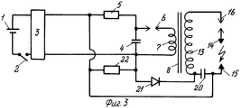
Фиг.3 Электрошоковое устройство по п.7, п.8, п.9 формулы изобретения с ограничивающим и разгрузочным резисторами технологии Shaped Pulse-EMD (схема электрическая).Figure 3 Electroshock device according to
Фиг.4 Электрошоковое устройство по п.7, п.9, п.10, п.12 формулы изобретения с разгрузочным и постоянным или подстраиваемым ограничивающим резисторами технологии Shaped Pulse - STUN GUN-EMD, и шунтирующим диодом низковольтной обмотки высоковольтного трансформатора (схема электрическая).Figure 4 The electric shock device according to
Осуществление изобретения.The implementation of the invention.
В зависимости от необходимости могут применяться различные варианты электрошокового устройства.Depending on the need, various variants of the stun device can be used.
Электрошоковое устройство патрона по п.1 п.2, п.3 формулы изобретения Фиг.1 состоит из низковольтного источника питания 1, представляющего собой аккумулятор или батарею, выключатель 2, преобразователь 3 низкого постоянного напряжения источника питания в постоянное напряжение 600-6000 В, соединенный с преобразователем 3 накопительный конденсатор 4, включенный параллельно в цепь, состоящую из ограничивающего сопротивления 5 газового или воздушного разрядника 6 и первичной обмотки 7 высоковольтного импульсного трансформатора 8. К преобразователю 3 подключен также дополнительный накопительный конденсатор, 9 одна обкладка которого соединена с выводом преобразователя 3 напрямую, а другая обкладка соединена с выводом преобразователя 3 через диод 10. Соединенная с диодом 10 обкладка конденсатора 9 соединена также с одним выводом диода 11, второй вывод которого соединен с одним выводом диода 12, второй вывод которого соединен с одним концом высоковольтной обмотки 13 трансформатора 8. Точка соединения диодов 11 и 12 соединена с одним поражающим электродом 14 электрошокового устройства. Второй конец обмотки 13 трансформатора 8 соединен с поражающим электродом 15 электрошокового устройства и с общей точкой соединения конденсаторов 4, 9 и вывода преобразователя 3.Electroshock device of the cartridge according to claim 1,
Низковольтная или высоковольтная обмотки высоковольтного импульсного трансформатора 8 должны быть сфазированы с выходом преобразователя 3 и диодами 10, 11, 12.The low-voltage or high-voltage windings of the high-
Устройство работает следующим образом. При включении выключателя 2 преобразователь 3 начинает заряжать конденсатор 4 через ограничивающее сопротивление 5, а через диод 10 - дополнительный конденсатор 9. Ограничивающее сопротивление 5 необходимо для гарантированного полного заряда конденсатора 9 до разряда конденсатора 4 в первичную обмотку 7 трансформатора 8, и гарантированному полному заряду конденсатора 9 в том случае, если прямое сопротивление высоковольтного диода (диодной сборки) достаточно велико. Разряду конденсаторов 4 и 9 через вторичную обмотку 13 трансформатора 8 препятствует диод 12. При достижении полного потенциала заряда конденсатора 4 напряжению зажигания разрядника 6 разрядник срабатывает, и конденсатор 4 разряжается через разрядник 6 в первичную обмотку 7 трансформатора 8. В то же время конденсатор 9 остается заряженным, так как его разряду в цепь разрядника 6 и первичной обмотки 7 трансформатора 8 препятствует диод 10 и сопротивление 5. Во вторичной обмотке 13 трансформатора 8 наводится ЭДС индукции при высоком потенциале. Шунтированию тока высоковольтного импульса через конденсатор 9 и 4 препятствует диод 11. Между поражающими электродами 14 и 15, расстояние между которыми выбирается для гарантированного пробоя по воздуху при потенциале, развиваемом вторичной обмоткой 13 трансформатора 8, происходит воздушный пробой. При этом сопротивление ионизированного пробоем разрядного канала между электродами 14 и 15 резко падает и конденсатор 9 начинает разряжаться в ионизированный воздушный канал через диод 11. Обычно применение (боевой разряд) электрошокирующего устройства происходит через одежду нападающего, т.е. через воздушные промежутки, определяемые толщиной одежды, однако в некоторых случаях применения поражающие электроды могут быть прижаты непосредственно к кожному покрову цели, имеющему сопротивление около 1000 Ом. В этом случае ток преобразователя 3 начинает течь по контуру один вывод преобразователя 3 диод 10, диод 11, электрод 14, сопротивление цели 1000 Ом, электрод 15, второй вывод преобразователя 3. Поражающее действие постоянного тока преобразователя 3 ничтожно, и электрошоковое устройство перестает быть эффективным. Для устранения протекания такого тока по указанному контуру между поражающим электродом 14 и точкой соединения диодов 11 и 12, или между электродом 15 и точкой соединения конца обмотки 13 с общей точкой конденсаторов 4 и 9, или между точкой соединения диодов 11 и 12, или между точкой соединения конденсатора 9 и диода 11, включен воздушный или газовый разрядник 16 с напряжением зажигания, равным или большим чем максимальное зарядное напряжение конденсатора 9. Разрядник 16, изображенный на Фиг.1 для примера, между электродом 14 и точкой соединения диода 11 с диодом 12 выполняет указанную функцию недопущения прохождения тока преобразователя 3 по указанному контуру на сопротивление цели до момента зажигания разрядника 6 и возникающему соответственно высоковольтному импульсу трансформатора 8. При прохождении высоковольтного импульса трансформатора 8 через сопротивление цели 1000 Ом и менее (вплоть до единиц Ом), разрядник 16, напряжение зажигания которого незначительно по сравнению с высоковольтным импульсом напряжения обмотки 13, зажигается потенциалом высоковольтного импульса, обеспечивая разряд конденсатора 9 прямо через цель (или воздушный промежуток и цель). Кроме указанной функции разрядник 16 обеспечивает функцию предохранения пользователя от воздействия постоянного остаточного напряжения на конденсаторе 4 и 9.The device operates as follows. When the
Для увеличения действующего на цель значения разрядного тока конденсатора 9 и недопущения пробоя диодов высоковольтными импульсами вторичной обмотки 13 трансформатора 8 в качестве диодов необходимо применять высоковольтные диодные сборки с возможно большими значениями допускаемого прямого импульсного тока. После выключения выключателя 2 и прекращения работы преобразователя 3 в определенный момент времени (до полного заряда конденсатора 4 и срабатывания разрядника 6) конденсатор 9 остается неразряженным и уже после выключения преобразователя 3 благодаря току утечки диода 10 начинает дозаряжать конденсатор 4. Такой процесс происходит при емкости конденсатора 9 значительно большей емкости конденсатора 4. При дозаряжании конденсатора 4 и срабатывании разрядника 6 происходит единичный высоковольтный импульс на высоковольтном трансформаторе 8 на выключенном устройстве. Такой неожиданный единичный импульс после выключения устройства представляет опасность для пользователя. Для устранения такого явления в зарядную цепь конденсатора 9 параллельно ему включен разгрузочный резистор 17 с большим сопротивлением. При выключении преобразователя 3 остаточный заряд конденсатора 9 стекает на резистор 17, не допуская дозаряда конденсатора 4.To increase the current value of the discharge current of the capacitor 9 and to prevent breakdown of the diodes by high-voltage pulses of the secondary winding 13 of the
Разряд конденсатора 9 в ионизированный канал происходит при каждом разряде конденсатора 4, таким образом демонстрационный разряд отличается от прототипа значительным зрительным эффектом и шумом разрядов.The discharge of the capacitor 9 into the ionized channel occurs at each discharge of the
Длительность импульса разряда конденсатора 9 в данном устройстве, как показали исследования, может достигать 1000 мкс и более при частоте следования импульсов 100-200 Гц и энергии отдельного импульса более 0,2 Дж. Таким образом в предлагаемом устройстве достигается совмещение характеристик параметров электроимпульсов STUN GUN и EMD технологий.The duration of the discharge pulse of the capacitor 9 in this device, as shown by studies, can reach 1000 μs or more at a pulse repetition rate of 100-200 Hz and an individual pulse energy of more than 0.2 J. Thus, the proposed device achieves the combination of the parameters of the electric pulses STUN GUN and EMD technology.
На Фиг.2 изображено устройство по п.1, п.3, п.4, п.6 формулы изобретения.Figure 2 shows the device according to claim 1,
От приведенного на Фиг.1 описания этот вариант устройства отличается иной последовательностью полярности включения диодов 10, 11 и 12, возможной при иной фазировке обмоток трансформатора 8, отсутствием ограничивающего резистора 5. Разрядник 16 по сравнению с описанием на Фиг.1 (поскольку расположение разрядника 16 в разрядной цепи конденсатора 9 имеет несколько вариантов) в данном варианте устройства включен в разрядную цепь конденсатора между диодом 11 и выводом конденсатора 9. Дополнительно введен постоянный или подстроечный резистор 18, включенный последовательно с диодом 10 в зарядную цепь дополнительного конденсатора 9 до точки соединения вывода конденсатора 9 с разрядником 16. Устройство работает следующим образом. Скорость заряда конденсатора 9 определяется величиной резистора 18 и всегда менее скорости заряда конденсатора 4. За время заряда конденсатора 9 до максимального напряжения заряда конденсатора 4 конденсатор 4 успевает многократно зарядиться до напряжения зажигания разрядника 6 и многократно разрядиться через разрядник 6 и первичную обмотку 7 трансформатора 8. Напряжение зажигания разрядника 16 подбирается примерно в 2-2,5 раза выше, чем напряжение зажигания разрядника 6. Потенциал заряда конденсатора 9 не может зажечь разрядник 16 даже при замыкании накоротко электродов 14 и 15 до тех пор тех пор, пока в цепи не наведется потенциал высоковольтного импульса обмотки 13, частично проходящий и через диод 11. При этом конденсатор 9 разряжается через разрядник 16 в ионизированный канал воздушного разряда между электродами 14 и 15, как по описанию на Фиг.1. После разряда конденсатора 9 описанный процесс повторяется.From the description given in FIG. 1, this variant of the device differs in a different sequence of switching on of the
Изменением сопротивления резистора 18, емкости конденсатора 9 и напряжения зажигания разрядника 16 можно устанавливать практически любую частоту разрядов конденсатора 9, менее чем частота разрядов конденсатора 4. Разрядник 16 в данном варианте устройства одновременно выполняет функцию предохранения пользователя от воздействия постоянного остаточного напряжения на конденсаторе 4 и 9.By changing the resistance of the
Практическое (легко осуществимое) регулирование частоты достигается изменением сопротивления резистора 18. Наилучшие физиологические результаты действия электроимпульсов достигаются при частоте разряда конденсатора 4 в 100-200 Гц, при энергии отдельного импульса в 0,05-0,1 Дж и его продолжительности 10-40 мкс и частоте разряда конденсатора 9 в 10-30 Гц, при энергии импульса в 1, 76 Дж, его продолжительности в 60 мкс и более. Таким образом в данном варианте предлагаемого устройства достигается совмещение характеристик параметров электроимпульсов STUN GUN и EMD-технологий.Practical (easily feasible) frequency regulation is achieved by changing the resistance of the
При необходимости получения однополярных высоковольтных импульсов (апериодических импульсов) трансформатора 8, обладающих повышенной физиологической эффективностью, первичная обмотка 7 трансформатора 8 шунтируется диодом 19, включенным обратнополярно относительно рабочей полярности накопительного конденсатора 4. В этом случае диод 19 срезает ток самоиндукции первичной обмотки 7 трансформатора 8, отсекая импульсы обратной полярности на обмотке 13 трансформатора 4, а кроме того, препятствует обратному току перезарядки конденсатора 4, что повышает электрический к.п.д. устройства.If it is necessary to obtain unipolar high-voltage pulses (aperiodic pulses) of the
На Фиг.3 изображено устройство по п.7, п.8, п.9 формулы изобретения, состоящее из низковольтного источника питания 1, представляющего собой аккумулятор или батарею, выключателя 2, преобразователя 3 низкого постоянного напряжения источника питания в постоянное напряжение 600-6000 В, соединенный с преобразователем 3 накопительный конденсатор 4, включенный параллельно в цепь, состоящую из ограничивающего сопротивления 5, газового или воздушного разрядника 6 и первичной обмотки 7 высоковольтного импульсного трансформатора 8. Дополнительный накопительный конденсатор 20 подключен последовательно высоковольтной обмотке 13 высоковольтного импульсного трансформатора 8, при этом вывод дополнительного конденсатора 20 является поражающим электродом 15 и непосредственно подключен к одному выводу преобразователя 3. Другой вывод дополнительного конденсатора 20, соединенный с одним концом обмотки 13 через диод 21, подключен к другому выводу преобразователя 3. В зарядную цепь дополнительного конденсатора 20 параллельно включен разгрузочный резистор 22.Figure 3 shows the device according to
Низковольтная или высоковольтная обмотки высоковольтного импульсного трансформатора 8 сфазированы с выходом преобразователя постоянного напряжения 3 и диодом 21, в разрядную цепь дополнительного конденсатора 20 включен воздушный или газовый разрядник 16 с напряжением зажигания большим, чем максимальное зарядное напряжение дополнительного накопительного конденсатора.The low-voltage or high-voltage windings of the high-
Последовательность присоединения диода 21 к тому или иному выводу конденсатора 20 и полярность его включения в данном устройстве многовариантна и определяется фазированием. Разрядник 16 выполняет функции, аналогичные описанным для Фиг.1.The sequence of connection of the
Устройство работает следующим образом. При включении выключателя 2 преобразователь 3 начинает заряжать конденсатор 4 через ограничивающее сопротивление 5 и через диод 21 дополнительный конденсатор 20.The device operates as follows. When the
Ограничивающее сопротивление 5 необходимо для гарантированного полного заряда конденсатора 20 до разряда конденсатора 4 в первичную обмотку 7 трансформатора 8, в том случае если прямое сопротивление диода достаточно велико.The limiting
При достижении потенциала заряда конденсатора 4 напряжению зажигания разрядника 6 разрядник срабатывает и конденсатор 4 разряжается через разрядник 6 в первичную обмотку 7 трансформатора 8. В то же время конденсатор 20 остается заряженным, так как его разряду в цепь разрядника 6 и первичной обмотки 7 трансформатора 8 препятствует диод 21. Во вторичной обмотке 13 трансформатора 8 наводится ЭДС индукции при высоком потенциале. Между поражающими электродами 14 и 15, расстояние между которыми выбирается для гарантированного пробоя по воздуху при потенциале, развиваемом вторичной обмоткой 13 трансформатора 8, происходит воздушный пробой. При этом сопротивление ионизированного пробоем разрядного канала между электродами 14 и 15 резко падает и конденсатор 20 начинает разряжаться в ионизированный воздушный канал через разрядник 16, напряжение зажигания которого незначительно по сравнению с импульсом напряжения вторичной обмотки 12.Upon reaching the charge potential of the
Разряд конденсатора 20 в ионизированный канал происходит при каждом разряде конденсатора 4, таким образом демонстрационный разряд отличается от прототипа значительным зрительным эффектом и шумом разрядов. После выключения выключателя 2 и прекращения работы преобразователя 3 в определенный момент времени (до полного заряда конденсатора 4 и срабатывания разрядника 6) конденсатор 20 остается неразряженным и уже после выключения преобразователя 3 благодаря току утечки диода 21 начинает дозаряжать конденсатор 4. Такой процесс происходит при емкости конденсатора 20 значительно большей емкости конденсатора 4. При дозаряжании конденсатора 4 и срабатывании разрядника 6 происходит единичный высоковольтный импульс на высоковольтном трансформаторе 8 на выключенном устройстве. Такой неожиданный единичный импульс после выключения устройства представляет опасность для пользователя. Для устранения такого явления в зарядную цепь конденсатора 20 параллельно включен разгрузочный резистор 22 с большим сопротивлением. При выключении преобразователя 3 остаточный заряд конденсатора 20 стекает на резистор 22, не дозаряжая конденсатор 4.The discharge of the
Длительность импульса разряда конденсатора 20 в данном устройстве, как показали исследования, может достигать 500-600 мкс при частоте следования импульсов 100-200 Гц, и энергии отдельного импульса более 0,2 Дж.The duration of the discharge pulse of the
Таким образом в варианте предлагаемого устройства достигается совмещение характеристик параметров электроимпульсов STUN GUN и EMD-технологий.Thus, in the variant of the proposed device, the combination of the characteristics of the parameters of the electric pulses STUN GUN and EMD technologies is achieved.
На Фиг.4 изображено устройство по п.7, п.9, п.10, п.12 формулы изобретения.Figure 4 shows the device according to
От приведенного на Фиг.3 описания этот вариант устройства отличается отсутствием ограничивающего сопротивления 5 и наличием постоянного или подстроечного ограничивающего сопротивления 23, включенного последовательно в зарядную цепь дополнительного конденсатора 20. Место включения резистора 23 в зарядную цепь конденсатора 20 может быть любым и не отражается на работе схемы.This variant of the device differs from the description in FIG. 3 by the absence of limiting
Устройство работает следующим образом. При включении выключателя 2 преобразователь 3 начинает заряжать конденсатор 4 и через диод 21 - дополнительный конденсатор 20. Скорость заряда конденсатора 20 определяется величиной сопротивления ограничивающего резистора 23 и всегда менее скорости заряда конденсатора 4. За время заряда конденсатора 20 до максимального напряжения заряда конденсатора 4, конденсатор 4 успевает многократно зарядиться до напряжения зажигания разрядника 6 и многократно разрядиться через разрядник 6 и первичную обмотку 7 трансформатора 8. Напряжение зажигания разрядника 16 подбирается примерно в 2-2,5 раза выше и больше, чем напряжение зажигания разрядника 6. Между поражающими электродами 14 и 15, расстояние между которыми выбирается для гарантированного пробоя по воздуху при потенциале, развиваемом вторичной обмоткой 13 трансформатора 8, каждый раз при разряде конденсатора 4 происходит воздушный пробой. Ток электроимпульса наведенного во вторичной обмотке 13 проходит через конденсатор 20, однако его разряда в ионизированный воздушный канал не происходит до тех пор пока потенциал заряда конденсатора 20 не достигает некоторой необходимой величины, определяемой проводимостью ионизированного канала концентрацией ионизированных частиц в ионизируемом канале. При достижении потенциала заряда конденсатора 20 необходимой для его разряда величины происходит разряд конденсатора 20 в ионизированный канал. После разряда конденсатора 20 описанный процесс повторяется.The device operates as follows. When the
Изменением сопротивления резистора 23, емкости конденсатора 20 и расстоянием между поражающими электродами 14 и 15 можно устанавливать практически любую частоту разрядов конденсатора 20 меньшую, чем частота разрядов конденсатора 4. Разрядник 16 в данном варианте устройства выполняет функцию предохранения пользователя от воздействия постоянного остаточного напряжения на конденсаторе 4 и 20 и недопущения разряда конденсатора 20 до его полной зарядки при непосредственном контакте электродов 14 и 15 с сопротивлением цели в 1000 Ом.By changing the resistance of the
При наличии некоторого определенного по расстоянию воздушного промежутка между поражающими электродами 14 и 15 и сопротивлением нагрузки (цели), частота следования импульсов разряда конденсатора 20 постоянна, но при уменьшении воздушного промежутка и приближения сопротивления между электродами 14 и 15 к 1000 Ом частота разрядов конденсатора 20 увеличивается и стремится приблизиться к частоте разрядов конденсатора 4. Регулирование частоты (уменьшение частоты разрядов конденсатора 20 при уменьшении величины воздушного промежутка) достигается увеличением сопротивления резистора 23 в зависимости от увеличения частоты разряда конденсатора 20. Такую регулировку оптимально осуществлять автоматически, т.е. при помощи дополнительного устройства, измеряющего частоту следования импульсов разряда конденсатора 20 и в зависимости от ее увеличения, увеличивающего сопротивление резистора 23.If there is some air gap between the
Необходимость наличия воздушного промежутка (значительного сопротивления) между электродами 14 и 15 для работы данного варианта устройства с большой частотой разряда конденсатора 4 и малой частотой разряда конденсатора 20 позволяет применять его в контактных действующих через одежду электрошокирующих устройствах и в дистанционных электрошоковых устройствах (ДЭШУ), не имеющих игл для проникания под одежду, т.е. в ДЭШУ с клеящимися (липкими) зондами. Наилучшие физиологические результаты действия электроимпульсов достигаются при характеристиках, указанных в описании к Фиг.2. Таким образом в варианте предлагаемого устройства достигается совмещение характеристик параметров электроимпульсов STUN GUN и EMD-технологий.The need for an air gap (significant resistance) between the
При необходимости получения однополярных высоковольтных импульсов (апериодических импульсов) трансформатора 8, обладающих повышенной физиологической эффективностью, первичная обмотка 7 трансформатора 8 шунтируется диодом 19, включенным обратнополярно относительно рабочей полярности накопительного конденсатора 4. В этом случае диод 19 срезает ток самоиндукции первичной обмотки 7 трансформатора 8, отсекая импульсы обратной полярности на обмотке 13 трансформатора 4, а кроме того, препятствует обратному току перезарядки конденсатора 4, что повышает электрический к.п.д. устройства.If it is necessary to obtain unipolar high-voltage pulses (aperiodic pulses) of the
Claims (12)
Translated fromRussianPriority Applications (1)
| Application Number | Priority Date | Filing Date | Title |
|---|---|---|---|
| RU2005139534/02ARU2305246C1 (en) | 2005-12-19 | 2005-12-19 | Electric shock device (modifications) |
Applications Claiming Priority (1)
| Application Number | Priority Date | Filing Date | Title |
|---|---|---|---|
| RU2005139534/02ARU2305246C1 (en) | 2005-12-19 | 2005-12-19 | Electric shock device (modifications) |
Publications (1)
| Publication Number | Publication Date |
|---|---|
| RU2305246C1true RU2305246C1 (en) | 2007-08-27 |
Family
ID=38597155
Family Applications (1)
| Application Number | Title | Priority Date | Filing Date |
|---|---|---|---|
| RU2005139534/02ARU2305246C1 (en) | 2005-12-19 | 2005-12-19 | Electric shock device (modifications) |
Country Status (1)
| Country | Link |
|---|---|
| RU (1) | RU2305246C1 (en) |
Cited By (3)
| Publication number | Priority date | Publication date | Assignee | Title |
|---|---|---|---|---|
| RU2410835C1 (en)* | 2009-12-23 | 2011-01-27 | Юрий Александрович Габлия | High-voltage pulse generator (versions) |
| RU2619061C2 (en)* | 2012-10-17 | 2017-05-11 | Юрий Олегович Ладягин | High-voltage generator |
| RU2668147C2 (en)* | 2015-02-10 | 2018-09-26 | Константин Дмитриевич Клочков | Method for elimination of capacitive breakdown pain feelings in electric shock and protection device for implementation thereof |
Citations (6)
| Publication number | Priority date | Publication date | Assignee | Title |
|---|---|---|---|---|
| GB2149068A (en)* | 1983-09-30 | 1985-06-05 | Lin Ching Yaw | Electronics baton for police |
| US5103366A (en)* | 1988-05-02 | 1992-04-07 | Gregory Battochi | Electrical stun guns and electrically conductive liquids |
| US5225623A (en)* | 1990-01-12 | 1993-07-06 | Philip | Self-defense device |
| RU2108526C1 (en)* | 1996-09-27 | 1998-04-10 | Павел Владимирович Богун | Electric shock device for self-defence |
| RU2150653C1 (en)* | 1999-01-28 | 2000-06-10 | Центральный физико-технический институт Министерства обороны Российской Федерации | Method for formation of current-conducting channel for remote injury by electroshock |
| RU2241191C1 (en)* | 2003-05-28 | 2004-11-27 | Центральный физико-технический институт Министерства обороны Российской Федерации | Jet electric shocker |
- 2005
- 2005-12-19RURU2005139534/02Apatent/RU2305246C1/enactiveIP Right Revival
Patent Citations (6)
| Publication number | Priority date | Publication date | Assignee | Title |
|---|---|---|---|---|
| GB2149068A (en)* | 1983-09-30 | 1985-06-05 | Lin Ching Yaw | Electronics baton for police |
| US5103366A (en)* | 1988-05-02 | 1992-04-07 | Gregory Battochi | Electrical stun guns and electrically conductive liquids |
| US5225623A (en)* | 1990-01-12 | 1993-07-06 | Philip | Self-defense device |
| RU2108526C1 (en)* | 1996-09-27 | 1998-04-10 | Павел Владимирович Богун | Electric shock device for self-defence |
| RU2150653C1 (en)* | 1999-01-28 | 2000-06-10 | Центральный физико-технический институт Министерства обороны Российской Федерации | Method for formation of current-conducting channel for remote injury by electroshock |
| RU2241191C1 (en)* | 2003-05-28 | 2004-11-27 | Центральный физико-технический институт Министерства обороны Российской Федерации | Jet electric shocker |
Cited By (6)
| Publication number | Priority date | Publication date | Assignee | Title |
|---|---|---|---|---|
| RU2410835C1 (en)* | 2009-12-23 | 2011-01-27 | Юрий Александрович Габлия | High-voltage pulse generator (versions) |
| WO2011084087A3 (en)* | 2009-12-23 | 2011-10-06 | Общество С Ограниченной Ответственностью "Ай Пи Солюшинс" | High-voltage pulse generator (variant embodiments) |
| CN102783027A (en)* | 2009-12-23 | 2012-11-14 | V&S世界有限责任公司 | High-voltage pulse generator (variant embodiments) |
| RU2619061C2 (en)* | 2012-10-17 | 2017-05-11 | Юрий Олегович Ладягин | High-voltage generator |
| RU2668147C2 (en)* | 2015-02-10 | 2018-09-26 | Константин Дмитриевич Клочков | Method for elimination of capacitive breakdown pain feelings in electric shock and protection device for implementation thereof |
| RU2668147C9 (en)* | 2015-02-10 | 2018-11-08 | Константин Дмитриевич Клочков | Method for elimination of capacitive breakdown pain feelings in electric shock and protection device for implementation thereof |
Similar Documents
| Publication | Publication Date | Title |
|---|---|---|
| US7145762B2 (en) | Systems and methods for immobilizing using plural energy stores | |
| RU2410835C1 (en) | High-voltage pulse generator (versions) | |
| US7778005B2 (en) | Electric disabling device with controlled immobilizing pulse widths | |
| US8254080B1 (en) | Systems and methods for providing current to inhibit locomotion | |
| US4486807A (en) | Non-lethal self defense device | |
| JP5421353B2 (en) | Immobilization system and method | |
| US7602597B2 (en) | Systems and methods for immobilization using charge delivery | |
| US7280340B2 (en) | Systems and methods for immobilization | |
| US7057872B2 (en) | Systems and methods for immobilization using selected electrodes | |
| US20070130815A1 (en) | Systems and methods for halting locomotion | |
| WO2007081360A2 (en) | Electronic disabling device having adjustable output pulse power | |
| US20080007887A1 (en) | Electrodes, devices, and methods for electro-incapacitation | |
| US7952850B1 (en) | Systems and methods for an electronic demotivator having a recovery switch | |
| RU2305246C1 (en) | Electric shock device (modifications) | |
| US7692915B1 (en) | Electric shock device | |
| RU2108526C1 (en) | Electric shock device for self-defence | |
| EP3936813A1 (en) | Shock current generator for electroshock weapons | |
| RU2619061C2 (en) | High-voltage generator | |
| RU2690432C2 (en) | High-voltage generator with preionisation in discharge gap | |
| RU2818376C1 (en) | Generator of damaging electric pulses of electric shock weapons | |
| US8390978B1 (en) | Incapacitation device and method with asynchronous T-wave avoidance | |
| DE2123498A1 (en) | Weapon for transmitting electrical energy to a target object | |
| WO2022114993A1 (en) | Electrical stunning method for a multiple-charge remote-acting electroshock weapon | |
| RU2668147C2 (en) | Method for elimination of capacitive breakdown pain feelings in electric shock and protection device for implementation thereof | |
| PLAINTIFFS’NOTICE et al. | CASE NO.: 07-80789 CIV-HURLEY/HOPKINS |
Legal Events
| Date | Code | Title | Description |
|---|---|---|---|
| MM4A | The patent is invalid due to non-payment of fees | Effective date:20081220 | |
| PC4A | Invention patent assignment | Effective date:20091203 | |
| PC4A | Invention patent assignment | Effective date:20100227 | |
| MM4A | The patent is invalid due to non-payment of fees | Effective date:20141220 | |
| NF4A | Reinstatement of patent | Effective date:20170111 | |
| PD4A | Correction of name of patent owner | ||
| PC41 | Official registration of the transfer of exclusive right | Effective date:20170203 | |
| PC41 | Official registration of the transfer of exclusive right | Effective date:20170427 | |
| MM4A | The patent is invalid due to non-payment of fees | Effective date:20171220 | |
| NF4A | Reinstatement of patent | Effective date:20180801 | |
| PC41 | Official registration of the transfer of exclusive right | Effective date:20200420 |