RU2303422C2 - Intervertebral prosthesis and system of intervertebral prostheses, in peculiar case, for cervical department of vertebral column - Google Patents
Intervertebral prosthesis and system of intervertebral prostheses, in peculiar case, for cervical department of vertebral columnDownload PDFInfo
- Publication number
- RU2303422C2 RU2303422C2RU2004130311/14ARU2004130311ARU2303422C2RU 2303422 C2RU2303422 C2RU 2303422C2RU 2004130311/14 ARU2004130311/14 ARU 2004130311/14ARU 2004130311 ARU2004130311 ARU 2004130311ARU 2303422 C2RU2303422 C2RU 2303422C2
- Authority
- RU
- Russia
- Prior art keywords
- cover
- prosthesis
- core
- thrust plate
- guide groove
- Prior art date
Links
Images


Classifications
- A—HUMAN NECESSITIES
- A61—MEDICAL OR VETERINARY SCIENCE; HYGIENE
- A61F—FILTERS IMPLANTABLE INTO BLOOD VESSELS; PROSTHESES; DEVICES PROVIDING PATENCY TO, OR PREVENTING COLLAPSING OF, TUBULAR STRUCTURES OF THE BODY, e.g. STENTS; ORTHOPAEDIC, NURSING OR CONTRACEPTIVE DEVICES; FOMENTATION; TREATMENT OR PROTECTION OF EYES OR EARS; BANDAGES, DRESSINGS OR ABSORBENT PADS; FIRST-AID KITS
- A61F2/00—Filters implantable into blood vessels; Prostheses, i.e. artificial substitutes or replacements for parts of the body; Appliances for connecting them with the body; Devices providing patency to, or preventing collapsing of, tubular structures of the body, e.g. stents
- A61F2/02—Prostheses implantable into the body
- A61F2/30—Joints
- A61F2/44—Joints for the spine, e.g. vertebrae, spinal discs
- A61F2/442—Intervertebral or spinal discs, e.g. resilient
- A61F2/4425—Intervertebral or spinal discs, e.g. resilient made of articulated components
- A—HUMAN NECESSITIES
- A61—MEDICAL OR VETERINARY SCIENCE; HYGIENE
- A61F—FILTERS IMPLANTABLE INTO BLOOD VESSELS; PROSTHESES; DEVICES PROVIDING PATENCY TO, OR PREVENTING COLLAPSING OF, TUBULAR STRUCTURES OF THE BODY, e.g. STENTS; ORTHOPAEDIC, NURSING OR CONTRACEPTIVE DEVICES; FOMENTATION; TREATMENT OR PROTECTION OF EYES OR EARS; BANDAGES, DRESSINGS OR ABSORBENT PADS; FIRST-AID KITS
- A61F2/00—Filters implantable into blood vessels; Prostheses, i.e. artificial substitutes or replacements for parts of the body; Appliances for connecting them with the body; Devices providing patency to, or preventing collapsing of, tubular structures of the body, e.g. stents
- A61F2/02—Prostheses implantable into the body
- A61F2/30—Joints
- A61F2002/30001—Additional features of subject-matter classified in A61F2/28, A61F2/30 and subgroups thereof
- A61F2002/30316—The prosthesis having different structural features at different locations within the same prosthesis; Connections between prosthetic parts; Special structural features of bone or joint prostheses not otherwise provided for
- A61F2002/30329—Connections or couplings between prosthetic parts, e.g. between modular parts; Connecting elements
- A61F2002/30383—Connections or couplings between prosthetic parts, e.g. between modular parts; Connecting elements made by laterally inserting a protrusion, e.g. a rib into a complementarily-shaped groove
- A61F2002/30387—Dovetail connection
- A—HUMAN NECESSITIES
- A61—MEDICAL OR VETERINARY SCIENCE; HYGIENE
- A61F—FILTERS IMPLANTABLE INTO BLOOD VESSELS; PROSTHESES; DEVICES PROVIDING PATENCY TO, OR PREVENTING COLLAPSING OF, TUBULAR STRUCTURES OF THE BODY, e.g. STENTS; ORTHOPAEDIC, NURSING OR CONTRACEPTIVE DEVICES; FOMENTATION; TREATMENT OR PROTECTION OF EYES OR EARS; BANDAGES, DRESSINGS OR ABSORBENT PADS; FIRST-AID KITS
- A61F2/00—Filters implantable into blood vessels; Prostheses, i.e. artificial substitutes or replacements for parts of the body; Appliances for connecting them with the body; Devices providing patency to, or preventing collapsing of, tubular structures of the body, e.g. stents
- A61F2/02—Prostheses implantable into the body
- A61F2/30—Joints
- A61F2002/30001—Additional features of subject-matter classified in A61F2/28, A61F2/30 and subgroups thereof
- A61F2002/30316—The prosthesis having different structural features at different locations within the same prosthesis; Connections between prosthetic parts; Special structural features of bone or joint prostheses not otherwise provided for
- A61F2002/30329—Connections or couplings between prosthetic parts, e.g. between modular parts; Connecting elements
- A61F2002/30383—Connections or couplings between prosthetic parts, e.g. between modular parts; Connecting elements made by laterally inserting a protrusion, e.g. a rib into a complementarily-shaped groove
- A61F2002/3039—Connections or couplings between prosthetic parts, e.g. between modular parts; Connecting elements made by laterally inserting a protrusion, e.g. a rib into a complementarily-shaped groove with possibility of relative movement of the rib within the groove
- A61F2002/30392—Rotation
- A—HUMAN NECESSITIES
- A61—MEDICAL OR VETERINARY SCIENCE; HYGIENE
- A61F—FILTERS IMPLANTABLE INTO BLOOD VESSELS; PROSTHESES; DEVICES PROVIDING PATENCY TO, OR PREVENTING COLLAPSING OF, TUBULAR STRUCTURES OF THE BODY, e.g. STENTS; ORTHOPAEDIC, NURSING OR CONTRACEPTIVE DEVICES; FOMENTATION; TREATMENT OR PROTECTION OF EYES OR EARS; BANDAGES, DRESSINGS OR ABSORBENT PADS; FIRST-AID KITS
- A61F2/00—Filters implantable into blood vessels; Prostheses, i.e. artificial substitutes or replacements for parts of the body; Appliances for connecting them with the body; Devices providing patency to, or preventing collapsing of, tubular structures of the body, e.g. stents
- A61F2/02—Prostheses implantable into the body
- A61F2/30—Joints
- A61F2002/30001—Additional features of subject-matter classified in A61F2/28, A61F2/30 and subgroups thereof
- A61F2002/30316—The prosthesis having different structural features at different locations within the same prosthesis; Connections between prosthetic parts; Special structural features of bone or joint prostheses not otherwise provided for
- A61F2002/30329—Connections or couplings between prosthetic parts, e.g. between modular parts; Connecting elements
- A61F2002/30383—Connections or couplings between prosthetic parts, e.g. between modular parts; Connecting elements made by laterally inserting a protrusion, e.g. a rib into a complementarily-shaped groove
- A61F2002/3039—Connections or couplings between prosthetic parts, e.g. between modular parts; Connecting elements made by laterally inserting a protrusion, e.g. a rib into a complementarily-shaped groove with possibility of relative movement of the rib within the groove
- A61F2002/30397—Limited lateral translation of the rib within a larger groove
- A—HUMAN NECESSITIES
- A61—MEDICAL OR VETERINARY SCIENCE; HYGIENE
- A61F—FILTERS IMPLANTABLE INTO BLOOD VESSELS; PROSTHESES; DEVICES PROVIDING PATENCY TO, OR PREVENTING COLLAPSING OF, TUBULAR STRUCTURES OF THE BODY, e.g. STENTS; ORTHOPAEDIC, NURSING OR CONTRACEPTIVE DEVICES; FOMENTATION; TREATMENT OR PROTECTION OF EYES OR EARS; BANDAGES, DRESSINGS OR ABSORBENT PADS; FIRST-AID KITS
- A61F2/00—Filters implantable into blood vessels; Prostheses, i.e. artificial substitutes or replacements for parts of the body; Appliances for connecting them with the body; Devices providing patency to, or preventing collapsing of, tubular structures of the body, e.g. stents
- A61F2/02—Prostheses implantable into the body
- A61F2/30—Joints
- A61F2002/30001—Additional features of subject-matter classified in A61F2/28, A61F2/30 and subgroups thereof
- A61F2002/30316—The prosthesis having different structural features at different locations within the same prosthesis; Connections between prosthetic parts; Special structural features of bone or joint prostheses not otherwise provided for
- A61F2002/30329—Connections or couplings between prosthetic parts, e.g. between modular parts; Connecting elements
- A61F2002/30383—Connections or couplings between prosthetic parts, e.g. between modular parts; Connecting elements made by laterally inserting a protrusion, e.g. a rib into a complementarily-shaped groove
- A61F2002/3039—Connections or couplings between prosthetic parts, e.g. between modular parts; Connecting elements made by laterally inserting a protrusion, e.g. a rib into a complementarily-shaped groove with possibility of relative movement of the rib within the groove
- A61F2002/30398—Sliding
- A61F2002/304—Sliding with additional means for limiting said sliding
- A—HUMAN NECESSITIES
- A61—MEDICAL OR VETERINARY SCIENCE; HYGIENE
- A61F—FILTERS IMPLANTABLE INTO BLOOD VESSELS; PROSTHESES; DEVICES PROVIDING PATENCY TO, OR PREVENTING COLLAPSING OF, TUBULAR STRUCTURES OF THE BODY, e.g. STENTS; ORTHOPAEDIC, NURSING OR CONTRACEPTIVE DEVICES; FOMENTATION; TREATMENT OR PROTECTION OF EYES OR EARS; BANDAGES, DRESSINGS OR ABSORBENT PADS; FIRST-AID KITS
- A61F2/00—Filters implantable into blood vessels; Prostheses, i.e. artificial substitutes or replacements for parts of the body; Appliances for connecting them with the body; Devices providing patency to, or preventing collapsing of, tubular structures of the body, e.g. stents
- A61F2/02—Prostheses implantable into the body
- A61F2/30—Joints
- A61F2002/30001—Additional features of subject-matter classified in A61F2/28, A61F2/30 and subgroups thereof
- A61F2002/30316—The prosthesis having different structural features at different locations within the same prosthesis; Connections between prosthetic parts; Special structural features of bone or joint prostheses not otherwise provided for
- A61F2002/30329—Connections or couplings between prosthetic parts, e.g. between modular parts; Connecting elements
- A61F2002/30476—Connections or couplings between prosthetic parts, e.g. between modular parts; Connecting elements locked by an additional locking mechanism
- A61F2002/30517—Connections or couplings between prosthetic parts, e.g. between modular parts; Connecting elements locked by an additional locking mechanism using a locking plate
- A—HUMAN NECESSITIES
- A61—MEDICAL OR VETERINARY SCIENCE; HYGIENE
- A61F—FILTERS IMPLANTABLE INTO BLOOD VESSELS; PROSTHESES; DEVICES PROVIDING PATENCY TO, OR PREVENTING COLLAPSING OF, TUBULAR STRUCTURES OF THE BODY, e.g. STENTS; ORTHOPAEDIC, NURSING OR CONTRACEPTIVE DEVICES; FOMENTATION; TREATMENT OR PROTECTION OF EYES OR EARS; BANDAGES, DRESSINGS OR ABSORBENT PADS; FIRST-AID KITS
- A61F2/00—Filters implantable into blood vessels; Prostheses, i.e. artificial substitutes or replacements for parts of the body; Appliances for connecting them with the body; Devices providing patency to, or preventing collapsing of, tubular structures of the body, e.g. stents
- A61F2/02—Prostheses implantable into the body
- A61F2/30—Joints
- A61F2002/30001—Additional features of subject-matter classified in A61F2/28, A61F2/30 and subgroups thereof
- A61F2002/30316—The prosthesis having different structural features at different locations within the same prosthesis; Connections between prosthetic parts; Special structural features of bone or joint prostheses not otherwise provided for
- A61F2002/30535—Special structural features of bone or joint prostheses not otherwise provided for
- A61F2002/30576—Special structural features of bone or joint prostheses not otherwise provided for with extending fixation tabs
- A61F2002/30578—Special structural features of bone or joint prostheses not otherwise provided for with extending fixation tabs having apertures, e.g. for receiving fixation screws
- A—HUMAN NECESSITIES
- A61—MEDICAL OR VETERINARY SCIENCE; HYGIENE
- A61F—FILTERS IMPLANTABLE INTO BLOOD VESSELS; PROSTHESES; DEVICES PROVIDING PATENCY TO, OR PREVENTING COLLAPSING OF, TUBULAR STRUCTURES OF THE BODY, e.g. STENTS; ORTHOPAEDIC, NURSING OR CONTRACEPTIVE DEVICES; FOMENTATION; TREATMENT OR PROTECTION OF EYES OR EARS; BANDAGES, DRESSINGS OR ABSORBENT PADS; FIRST-AID KITS
- A61F2/00—Filters implantable into blood vessels; Prostheses, i.e. artificial substitutes or replacements for parts of the body; Appliances for connecting them with the body; Devices providing patency to, or preventing collapsing of, tubular structures of the body, e.g. stents
- A61F2/02—Prostheses implantable into the body
- A61F2/30—Joints
- A61F2002/30001—Additional features of subject-matter classified in A61F2/28, A61F2/30 and subgroups thereof
- A61F2002/30316—The prosthesis having different structural features at different locations within the same prosthesis; Connections between prosthetic parts; Special structural features of bone or joint prostheses not otherwise provided for
- A61F2002/30535—Special structural features of bone or joint prostheses not otherwise provided for
- A61F2002/30604—Special structural features of bone or joint prostheses not otherwise provided for modular
- A61F2002/30616—Sets comprising a plurality of prosthetic parts of different sizes or orientations
- A—HUMAN NECESSITIES
- A61—MEDICAL OR VETERINARY SCIENCE; HYGIENE
- A61F—FILTERS IMPLANTABLE INTO BLOOD VESSELS; PROSTHESES; DEVICES PROVIDING PATENCY TO, OR PREVENTING COLLAPSING OF, TUBULAR STRUCTURES OF THE BODY, e.g. STENTS; ORTHOPAEDIC, NURSING OR CONTRACEPTIVE DEVICES; FOMENTATION; TREATMENT OR PROTECTION OF EYES OR EARS; BANDAGES, DRESSINGS OR ABSORBENT PADS; FIRST-AID KITS
- A61F2/00—Filters implantable into blood vessels; Prostheses, i.e. artificial substitutes or replacements for parts of the body; Appliances for connecting them with the body; Devices providing patency to, or preventing collapsing of, tubular structures of the body, e.g. stents
- A61F2/02—Prostheses implantable into the body
- A61F2/30—Joints
- A61F2002/30001—Additional features of subject-matter classified in A61F2/28, A61F2/30 and subgroups thereof
- A61F2002/30621—Features concerning the anatomical functioning or articulation of the prosthetic joint
- A61F2002/30649—Ball-and-socket joints
- A61F2002/3065—Details of the ball-shaped head
- A—HUMAN NECESSITIES
- A61—MEDICAL OR VETERINARY SCIENCE; HYGIENE
- A61F—FILTERS IMPLANTABLE INTO BLOOD VESSELS; PROSTHESES; DEVICES PROVIDING PATENCY TO, OR PREVENTING COLLAPSING OF, TUBULAR STRUCTURES OF THE BODY, e.g. STENTS; ORTHOPAEDIC, NURSING OR CONTRACEPTIVE DEVICES; FOMENTATION; TREATMENT OR PROTECTION OF EYES OR EARS; BANDAGES, DRESSINGS OR ABSORBENT PADS; FIRST-AID KITS
- A61F2/00—Filters implantable into blood vessels; Prostheses, i.e. artificial substitutes or replacements for parts of the body; Appliances for connecting them with the body; Devices providing patency to, or preventing collapsing of, tubular structures of the body, e.g. stents
- A61F2/02—Prostheses implantable into the body
- A61F2/30—Joints
- A61F2/44—Joints for the spine, e.g. vertebrae, spinal discs
- A61F2/442—Intervertebral or spinal discs, e.g. resilient
- A61F2/4425—Intervertebral or spinal discs, e.g. resilient made of articulated components
- A61F2002/443—Intervertebral or spinal discs, e.g. resilient made of articulated components having two transversal endplates and at least one intermediate component
- A—HUMAN NECESSITIES
- A61—MEDICAL OR VETERINARY SCIENCE; HYGIENE
- A61F—FILTERS IMPLANTABLE INTO BLOOD VESSELS; PROSTHESES; DEVICES PROVIDING PATENCY TO, OR PREVENTING COLLAPSING OF, TUBULAR STRUCTURES OF THE BODY, e.g. STENTS; ORTHOPAEDIC, NURSING OR CONTRACEPTIVE DEVICES; FOMENTATION; TREATMENT OR PROTECTION OF EYES OR EARS; BANDAGES, DRESSINGS OR ABSORBENT PADS; FIRST-AID KITS
- A61F2220/00—Fixations or connections for prostheses classified in groups A61F2/00 - A61F2/26 or A61F2/82 or A61F9/00 or A61F11/00 or subgroups thereof
- A61F2220/0025—Connections or couplings between prosthetic parts, e.g. between modular parts; Connecting elements
- A—HUMAN NECESSITIES
- A61—MEDICAL OR VETERINARY SCIENCE; HYGIENE
- A61F—FILTERS IMPLANTABLE INTO BLOOD VESSELS; PROSTHESES; DEVICES PROVIDING PATENCY TO, OR PREVENTING COLLAPSING OF, TUBULAR STRUCTURES OF THE BODY, e.g. STENTS; ORTHOPAEDIC, NURSING OR CONTRACEPTIVE DEVICES; FOMENTATION; TREATMENT OR PROTECTION OF EYES OR EARS; BANDAGES, DRESSINGS OR ABSORBENT PADS; FIRST-AID KITS
- A61F2310/00—Prostheses classified in A61F2/28 or A61F2/30 - A61F2/44 being constructed from or coated with a particular material
- A61F2310/00005—The prosthesis being constructed from a particular material
- A61F2310/00011—Metals or alloys
Landscapes
- Health & Medical Sciences (AREA)
- Engineering & Computer Science (AREA)
- Biomedical Technology (AREA)
- Neurology (AREA)
- Orthopedic Medicine & Surgery (AREA)
- Cardiology (AREA)
- Oral & Maxillofacial Surgery (AREA)
- Transplantation (AREA)
- Heart & Thoracic Surgery (AREA)
- Vascular Medicine (AREA)
- Life Sciences & Earth Sciences (AREA)
- Animal Behavior & Ethology (AREA)
- General Health & Medical Sciences (AREA)
- Public Health (AREA)
- Veterinary Medicine (AREA)
- Prostheses (AREA)
Abstract
Description
Translated fromRussianМежпозвонковые протезы предназначены для замены межпозвонковых дисков. Они состоят из двух крышек, внешние поверхности которых предназначены для соединения со смежными позвонками, и заключенного под крышками шарнирного устройства. У известного типа протеза (WO 01/01893, FR-A-2718635) верхняя крышка на своей внутренней стороне имеет вогнуто-сферическую шарнирную поверхность, которая взаимодействует с образованием шарнира с выпукло-сферической верхней стороной выполненного из полиэтилена ядра протеза. Плоская нижняя сторона и боковые грани ядра протеза соответствующим образом размещаются в седле, которое образовано нижней крышкой. Это седло состоит из плоской донной поверхности и боковой стороны, выступающей над этой поверхностью и окружающей ее с трех сторон (боковые и спинная). На боковых сторонах кромка выполнена в виде двух проходящих в основном в АР-направлении (передне-заднее направление) краевых планок, которые выполнены соответствующими пазам или выступам на боковой грани ядра протеза. На вентральной (обращенной к брюшной полости) стороне боковая сторона крышки выполнена открытой, так что ядро протеза может быть вдвинуто в АР-направлении в крышку протеза. В данном положении ядро протеза благодаря взаимодействию выступов и канавок в крышке и ядре протеза защищено от разъединения с крышкой. В частности, оно не может из заданного положения сместиться (дорсально) в сторону спинного мозга, так как крышки при изгибе раздвигаются в дорсальном направлении.Intervertebral prostheses are designed to replace intervertebral discs. They consist of two covers, the outer surfaces of which are intended for connection with adjacent vertebrae, and a hinged device enclosed under the covers. For a known type of prosthesis (WO 01/01893, FR-A-2718635), the top cover has a concave-spherical hinge surface on its inner side that interacts with the formation of a hinge with the convex-spherical upper side of the prosthesis core made of polyethylene. The flat underside and lateral faces of the prosthesis core are appropriately located in the saddle, which is formed by the lower cover. This saddle consists of a flat bottom surface and a lateral side protruding above this surface and surrounding it on three sides (lateral and dorsal). On the lateral sides, the edge is made in the form of two edge strips extending mainly in the AR direction (anteroposterior direction), which are made corresponding to grooves or protrusions on the lateral face of the prosthesis core. On the ventral (facing the abdominal cavity) side, the lateral side of the cover is open so that the core of the prosthesis can be pushed in the AP direction into the cover of the prosthesis. In this position, the core of the prosthesis due to the interaction of the protrusions and grooves in the cover and the core of the prosthesis is protected from separation from the cover. In particular, it cannot shift (dorsally) from a given position towards the spinal cord, since the covers are moved apart in a dorsal direction when bent.
Известны межпозвонковые протезы, у которых боковая сторона нижней крышки распространяется и на вентральную сторону (ЕР-В-471821, US-A-5425773). Однако это связано с тем недостатком, что ядро протеза либо не может быть вставлено после установки крышек, либо в седле нижней крышки не может быть защищено от разъединения. Изобретение касается исключительно протезов такого типа, у которых седло нижней крышки выполнено в виде вентрально открытой направляющей для установки ядра протеза, которое может быть вставлено в протез после имплантации крышек.Intervertebral prostheses are known in which the side of the lower cover extends to the ventral side (EP-B-471821, US-A-5425773). However, this is due to the disadvantage that the prosthesis core either cannot be inserted after the covers are installed, or cannot be protected from separation in the saddle of the lower cover. The invention relates exclusively to prostheses of this type, in which the saddle of the lower cover is made in the form of a ventrally open guide for installing the prosthesis core, which can be inserted into the prosthesis after implantation of the covers.
Чтобы ядро протеза не могло выйти из седла в вентральную сторону, у известных протезов такого вида предусмотрен стопорный упор (FR-A-2 718 635, WO 01/01893). Он состоит из взаимодействующих выступов и выемок в нижней части ядра протеза с одной стороны и донной поверхности седла с другой стороны. Чтобы при вдвижении ядра протеза в седло они могли вступить во взаимодействие друг с другом, седло, которое выполнено из эластичного полимерного материала, должно упруго деформироваться перед установкой этого элемента. Это имеет тот недостаток, что вследствие соответствующего упругого деформирования ядра протеза может снова произойти разъединение частей протеза. Правда, надежность соединения может быть повышена за счет придания ядру протеза возможно большей жесткости. Однако это усложнит оператору задачу по установке ядра протеза в седло. Кроме того может случиться так, что упорный элемент по каким-то случайным причинам, оставшимся для оператора не известными, не займет или не полностью встанет в заданное положение, например, из-за того, что в выемку попало какое-то инородное тело или ядро протеза из-за каких-то случайных препятствий не точно заняло свое место в седле.In order to prevent the prosthesis’s core from going out of the saddle to the ventral side, a known stop is provided for known prostheses of this kind (FR-A-2 718 635, WO 01/01893). It consists of interacting protrusions and grooves in the lower part of the prosthesis core on the one hand and the bottom surface of the saddle on the other hand. So that when the prosthesis core is inserted into the saddle, they can interact with each other, the saddle, which is made of an elastic polymer material, must elastically deform before installing this element. This has the disadvantage that due to the corresponding elastic deformation of the core of the prosthesis, separation of the parts of the prosthesis can again occur. True, the reliability of the connection can be improved by giving the prosthesis core the greatest possible rigidity. However, this will complicate the task for the operator to install the prosthesis core in the saddle. In addition, it may happen that the thrust element, for some random reasons that are not known to the operator, does not occupy or does not fully fall into a predetermined position, for example, due to the fact that some foreign body or core fell into the recess the denture did not exactly take its place in the saddle due to some random obstructions.
Задачей изобретения является создание межпозвонкового протеза описанного типа, при котором ядро надежно удерживается в протезе и не создается сложностей при операции.The objective of the invention is the creation of an intervertebral prosthesis of the described type, in which the nucleus is held securely in the prosthesis and does not create difficulties during surgery.
Решение, соответствующее изобретению, содержится в комбинации признаков пункта 1 формулы изобретения.The solution according to the invention is contained in a combination of features of
Чтобы обеспечить ядру протеза возможность перемещения в АР-направлении, что необходимо для вдвижения в седло, седло выполнено в виде направляющего устройства, ориентированного в АР-направлении. Оно может быть выполнено в виде расположенных на противоположных сторонах параллельных направляющих полозьев, между которыми ядро удерживается таким образом, что оно может перемещаться только в АР-направлении. При этом направляющие полозья целесообразно выполнять в виде пазов, с которыми взаимодействуют входящие в эти пазы выступы ядра. Таким образом создается препятствие разъединению ядра и удерживающей его крышки. Это дает то преимущество, что устройства, предусмотренные для ограничения перемещения, не должны быть высокими, что не создает опасности возникновения помехи относительному смещению крышек. Чтобы ядро не выскользнуло из направляющих в дорсальную или вентральную сторону, предусмотрены соответствующие упоры. Упор от смещения в дорсальную сторону предпочтительно жестко соединен с образующей седло (или направляющие) крышкой. На вентральной стороне предусмотрен упор, который может быть выведен из стопорящего положения, для более легкой установки ядра после имплантации крышки. После этого упор фиксируется в положении, в котором он препятствует смещению ядра.To provide the prosthesis core with the ability to move in the AR direction, which is necessary for moving into the saddle, the saddle is made in the form of a guiding device oriented in the AR direction. It can be made in the form of parallel guide rails located on opposite sides, between which the core is held in such a way that it can only move in the AP direction. In this case, the guide rails are expediently performed in the form of grooves with which the protrusions of the nucleus entering into these grooves interact. Thus, an obstacle is created to the separation of the core and its cover. This gives the advantage that the devices provided for restricting movement should not be high, which does not pose a risk of interference with the relative displacement of the covers. To prevent the core from sliding out of the guides to the dorsal or ventral side, appropriate stops are provided. The emphasis against displacement towards the dorsal side is preferably rigidly connected to the cover forming the saddle (or guides). A support is provided on the ventral side, which can be removed from the locking position, for easier installation of the nucleus after implantation of the cap. After that, the emphasis is fixed in a position in which it prevents the displacement of the core.
На вентральной стороне крышки, образующей ядро, предусмотрена направляющая скольжения, в которой или по которой может быть передвинут упор из стопорящего в свободное положение. Благодаря этому создается предпосылка для осознанного перевода упора оператором в стопорящее положение. Таким образом уверенно обеспечивается стопорящее положение упора.On the ventral side of the lid forming the core, a sliding guide is provided in which or along which the stop can be moved from the stop to the free position. This creates the prerequisite for the conscious transfer of the stop by the operator to the locking position. In this way, the stop position of the stop is surely ensured.
Особенно целесообразным представляется вариант исполнения изобретения, при котором направляющая скольжения выполнена в виде направляющего паза, проходящего поперечно направляющему устройству, при этом в паз входит упор, выполненный в виде упорной пластины.An embodiment of the invention seems to be particularly expedient in which the sliding guide is made in the form of a guide groove extending transversely to the guide device, and a stop made in the form of a stop plate enters the groove.
Например, направляющий паз может проходить поперечно плоскости простирания крышки. Таким образом в стопорящем положении упорная пластина частично входит в паз и удерживается там, и частично выступает над донной поверхностью седла и фиксирует ядро протеза в седле. В незафиксированном положении упорная пластина располагается в пазу ниже донной поверхности седла полностью или может быть вынута из паза вверх или вниз.For example, the guide groove may extend transversely to the strike plane of the cover. Thus, in the locking position, the abutment plate partially enters the groove and is held there, and partially protrudes above the bottom surface of the saddle and fixes the prosthesis core in the saddle. In an unsecured position, the thrust plate is located in the groove below the bottom surface of the seat completely or can be removed from the groove up or down.
Вместо этого направляющий паз может проходить параллельно плоскости простирания первой крышки и перпендикулярно АР-направлению. В этом случае для помещения в стопорящее положение упорная пластина вдвигается в направляющий паз сбоку.Instead, the guide groove may extend parallel to the strike plane of the first cover and perpendicular to the AP direction. In this case, to place in the locking position, the thrust plate is pushed into the guide groove on the side.
В каждом случае должны иметься крепежные устройства, с помощью которых упорная пластина крепится в стопорящем положении. Особенно надежное крепление обеспечивается в случае, если упорную пластину крепят поперечным винтом, потому что упорная пластина может быть извлечена только тогда, когда будет вывернут винт. Для этой цели направляющий паз снабжен, по меньшей мере, одним отверстием под винт, упорная пластина также имеет отверстие под винт, которое совпадает с отверстием в направляющем пазу, когда пластина занимает стопорящее положение. Это исполнение предпочтительно, когда направляющий паз расположен в крепежном фланце, который предусмотрен на вентральной стороне крышки, образующей седло.In each case, there must be fasteners with which the thrust plate is fixed in the locking position. Particularly reliable fastening is provided if the thrust plate is secured with a transverse screw, because the thrust plate can only be removed when the screw is loosened. For this purpose, the guide groove is provided with at least one screw hole, the thrust plate also has a screw hole, which coincides with the hole in the guide groove when the plate is in the locking position. This design is preferable when the guide groove is located in the mounting flange, which is provided on the ventral side of the cover forming the seat.
Другой способ крепления упорной пластины в направляющем шлице заключается в том, что ядро протеза имеет деталь, которая покрывает упорную пластину, находящуюся в направляющем пазу. Подобное средство для покрытия может быть выполнено в виде шлица в ядре протеза, который находится на одной линии с направляющим пазом, когда ядро протеза занимает в седле заданное положение. Направляющий паз в крышке с одной стороны и находящийся с ним на одной линии шлиц в ядре протеза с другой стороны образуют установочное устройство для упорной пластины, в которое она легко вдвигается сбоку.Another way of attaching the abutment plate in the guide slot is that the prosthesis core has a part that covers the abutment plate located in the guide groove. Such a coating tool can be made in the form of a slot in the core of the prosthesis, which is in line with the guide groove when the core of the prosthesis occupies a predetermined position in the saddle. The guide groove in the cover on one side and the slot located on the same line in the core of the prosthesis on the other hand form an installation device for the thrust plate into which it is easily pushed to the side.
Другая возможность крепления состоит в том, что упорная пластина имеет легко загибаемую крепежную лапку, направленную к направляющему пазу и выступающую над направляющим пазом в стопорящем положении пластины. Эта лапка после установки загибается оператором таким образом, что она выходит за плоскость упорной пластины и благодаря этому препятствует возвратному смещению в направляющем пазу.Another possibility of attachment is that the thrust plate has an easily bent mounting tab directed toward the guide groove and protrudes above the guide groove in the locking position of the plate. After installation, this foot is bent by the operator in such a way that it extends beyond the plane of the thrust plate and thereby prevents reverse movement in the guide groove.
При другом варианте исполнения упорной пластины перевод ее из свободного в стопорящее положение происходит не по прямой линии, а за счет поворота. В этом случае скользящая направляющая, в которую входит упорная пластина, образована направляющей поверхностью скольжения, проходящей на вентральной стороне крышки поперечно АР-направлению, и поднимающимся по ней откидным болтом, на котором закреплена с возможностью поворота упорная пластина. Упорная пластина имеет язычок, который выступает над донной поверхностью седла, когда упорная пластина находится в стопорящем повернутом положении, и таким образом препятствует выходу ядра протеза из седла. При свободном положении пластины этот запорный язычок опущен ниже донной поверхности седла. Целесообразно, чтобы направляющая поверхность скольжения, на которой удерживается упорная пластина, была образована торцевой поверхностью крепежного фланца. В нем рядом с откидным болтом имеется, по меньшей мере, одно отверстие под винт. Согласно изобретению упорная пластина может быть закреплена с помощью винта, устанавливаемого в это отверстие за счет того, что винт своей головкой, находящейся над отверстием, взаимодействует с выступом.In another embodiment of the thrust plate, its translation from the free to the locking position occurs not in a straight line, but due to rotation. In this case, the sliding guide, into which the thrust plate enters, is formed by a sliding guide surface extending on the ventral side of the cover transverse to the AP direction, and a hinged bolt that rises along it, on which the thrust plate is rotated. The abutment plate has a tongue that protrudes above the bottom surface of the seat when the abutment plate is in a locked rotated position, and thus prevents the prosthesis core from leaving the seat. In the free position of the plate, this locking tongue is lowered below the bottom surface of the saddle. It is advisable that the sliding guide surface on which the thrust plate is held is formed by the end surface of the mounting flange. At it, next to the hinged bolt, there is at least one screw hole. According to the invention, the thrust plate can be fixed with a screw installed in this hole due to the fact that the screw, with its head located above the hole, interacts with the protrusion.
Упор согласно изобретению пригоден не только для случаев, в которых ядро протеза занимает неподвижное положение в седле, а также и для случаев, когда задана свобода перемещения, в частности в АР-направлении. Направляющее устройство, образованное седлом для ядра протеза, может быть использовано для обеспечения его вдвижения, но и для постоянной возможности перемещения. Это может иметь преимущество, в частности, при цервикальных (шейных) протезах, в которых шарнирная поверхность ядра протеза занимает почти всю крышку. В эти случаях радиус кривизны шарнирной поверхности можно было бы уменьшить, чтобы сделать меньшей конструктивную высоту протеза. В этих случаях подвижность протеза в АР-направлении будет подобна подвижности в естественных условиях. Особый аспект изобретения заключается в этой связи в том, что в системах протезов наряду с теми, которые дают возможность подвижности в АР-направлении (передне-задней подвижности), могут быть и другие, имеющие ту же внешнюю форму и не имеющие подвижности в АР-направлении между ядром протеза и заключающей его крышкой. Это дает возможность врачу при операции принимать решение, хочет ли он предусмотреть подвижность в АР-направлении или нет. С точки зрения целесообразности крышки имеющих подвижность в АР-направлении протезов и не имеющих ее выполнены одинаково, различными являются только ядра протезов. Однако может быть также предусмотрено, чтобы ядра протезов и образующие шарнир крышки во всех типах совпадали, а различными были бы только крышки, удерживающие ядро протеза. Наконец имеется возможность, чтобы совпадали все три элемента конструкции, за исключением местных изменений в упоре, который с вентральной стороны ограничивает перемещение ядра протеза в АР-направлении.The emphasis according to the invention is suitable not only for cases in which the prosthesis core is stationary in the saddle, but also for cases when freedom of movement is specified, in particular in the AR direction. The guide device formed by the saddle for the prosthesis core can be used to ensure its movement, but also for constant possibility of movement. This may be advantageous, in particular, for cervical (cervical) prostheses in which the hinged surface of the prosthetic nucleus occupies almost the entire cover. In these cases, the radius of curvature of the hinge surface could be reduced to make the design height of the prosthesis smaller. In these cases, the mobility of the prosthesis in the AR direction will be similar to mobility in vivo. A particular aspect of the invention lies in the fact that in prosthetic systems, along with those that enable mobility in the AR direction (anteroposterior mobility), there may be others having the same external shape and not having mobility in the AP the direction between the core of the prosthesis and the lid enclosing it. This allows the doctor during the operation to decide whether he wants to provide mobility in the AR direction or not. From the point of view of the feasibility of the cover with the mobility in the AR direction of the prosthesis and not having it performed equally, only the prosthesis nuclei are different. However, it can also be provided that the prosthetic nuclei and the hinge-forming covers coincide in all types, and only the covers holding the prosthetic core are different. Finally, it is possible that all three structural elements coincide, with the exception of local changes in the emphasis, which on the ventral side limits the movement of the prosthesis core in the AR direction.
Из упоминания нижней и верхней крышки не следует, что образующая седло крышка должна быть постоянно внизу. Напротив может быть выбрано и обратное решение. Поэтому в формуле изобретения в общем говорится о первой и второй крышках.From the mention of the lower and upper covers it does not follow that the cover forming the saddle must be constantly below. On the contrary, the inverse solution can be chosen. Therefore, the claims generally refer to the first and second covers.
Также в изобретение предусмотрена система межпозвонковых протезов, в частности для шейного отдела позвоночника, состоящих в основном из первой, соединяемой с первым позвонком, крышки, второй, соединяемой со вторым позвонком, крышки и ядра протеза, удерживаемого в седле первой крышки, при этом ядро образует шарнир со второй крышкой, причем в системе используются межпозвонковые протезы согласно изобретению или протезы с совпадающей внешней формой, ядра которых не обладают подвижностью по отношению к первой крышке в передне-заднем направлении. Предпочтительно, если крышки соответствующих протезов с или без передне-задней подвижности выполнены совпадающими между собой, а ядра протезов выполнены отличающимися. Также предпочтительно, что вторая крышка и ядро протеза с или без передне-задней подвижности выполнены совпадающими между собой, а первая крышка выполнена отличающейся. В варианте осуществления первая и вторая крышки, а также ядро протезов с или без передне-задней подвижности выполнены совпадающими между собой, а упор, который ограничивает подвижность ядра в вентральную сторону, выполнен отличающимся.The invention also provides a system of intervertebral prostheses, in particular for the cervical spine, consisting mainly of the first, connected to the first vertebra, the cover, the second, connected to the second vertebra, the cover and the core of the prosthesis held in the saddle of the first cover, while the core forms hinge with a second cover, and the system uses intervertebral prostheses according to the invention or prostheses with a matching external shape, the nuclei of which do not have mobility with respect to the first cover in the anteroposterior direction NII. Preferably, if the covers of the respective prostheses with or without anteroposterior mobility are made matching, and the prosthetic nuclei are made different. It is also preferable that the second cover and the core of the prosthesis with or without anteroposterior mobility are made matching, and the first cover is made different. In an embodiment, the first and second covers, as well as the prosthesis core with or without anteroposterior mobility, are made identical, and the emphasis, which limits the mobility of the nucleus to the ventral side, is made different.
Предпочтительные варианты исполнения ниже более подробно поясняются с помощью чертежей. На них показано:Preferred embodiments are explained in more detail below with reference to the drawings. They show:
Фиг.1 - фронтальный разрез;Figure 1 - frontal section;
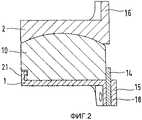
Фиг.2 - сагиттальный разрез и;Figure 2 - sagittal section and;
Фиг.3 - первый вариант исполнения в разобранном виде;Figure 3 - the first embodiment in disassembled form;
Фиг.4 - вариант первого варианта исполнения;4 is a variant of the first embodiment;
Фиг.5 - сагиттальный разрез;5 is a sagittal section;
Фиг.6 - второй вариант исполнения в разобранном виде;6 is a second embodiment in disassembled form;
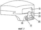
Фиг.7 - второй вариант исполнения с переставленной упорной пластиной;7 is a second embodiment with a rearranged thrust plate;
Фиг.8 и 9 - два сагиттальных разреза по линиям В и соответственно С на фиг.10;Figs. 8 and 9 show two sagittal sections along lines B and C respectively in Fig. 10;
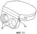
Фиг.10 и 11 - два перспективных изображения третьего варианта исполнения;10 and 11 are two perspective images of a third embodiment;
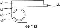
Фиг.12 - упорная пластина в третьем варианте исполнения;12 is a thrust plate in a third embodiment;
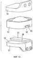
Фиг.13 - четвертый вариант исполнения в разобранном виде;Fig - the fourth embodiment in disassembled form;
Фиг.14 - вариант нижней крышки в четвертом варианте исполнения.Fig - variant of the lower cover in the fourth embodiment.
Первая и вторая крышки, в варианте осуществления изобретения представленные как нижняя крышка 1 и верхняя крышка 2, в первом варианте исполнения имеют внешние поверхности 3 и соответственно 4, которые предназначены для закрепления на соответствующих позвонках. Они выполнены преимущественно плоскими. Но возможны и другие в основном плоские конфигурации, включающие подходящие поверхностные структуры для лучшего крепления к кости. Крышки выполнены преимущественно из металла.The first and second covers, in the embodiment of the invention presented as the
Нижняя крышка 1 повернута к верхней крышке 2 плоской донной поверхностью 5, с трех сторон которой находится борт 6, который выше внутренней проточки имеет направленный внутрь выступ 7. Нижняя крышка 1 на виде сверху имеет форму овала или приблизительно прямоугольника.The
Донная поверхность 5 и борт 6 нижней крышки 1 образуют седло для ядра протеза 10, выполненного из благоприятствующего скольжению материала, например из полиэтилена. Ядро протеза имеет соответствующую донной поверхности 5 плоскую нижнюю поверхность, которая сбоку и с дорсальной стороны ограничена краевым выступом 11, выше которого находится канавка 12. Выступ 11 взаимодействует с проточкой в борту 6 ниже выступа 7. Выступ 7 входит в зацепление с канавкой 12. Благодаря этому ядро протеза 10 фиксируется от разъединения с нижней крышкой 1. Между бортом 6, нижней крышкой 1 и краем ядра 10 имеется зазор. На сторонах 8, 9 ветви борта 6 выступ 7, выступ 11 и канавка 12 проходят прямолинейно и параллельно друг другу.The
Ядро 10 протеза на виде сверху в основном повторяет очертания нижней крышки 1 и верхней крышки 2. В частности, он перекрывает борт 6, так что величина скользящей поверхности 22, которая образует верхнюю сторону ядра, из-за наличия борта 6 не уменьшается. Борт 6 может иметь высоту меньшую, чем высота ядра 10. Несмотря на это ядро не может выйти из пространства между крышками 1 и 2, так как этому препятствует взаимодействие выступа 7 и выступа 11.The
На вентральной стороне крышек 1, 2 предусмотрены расположенные к ним примерно под прямым углом крепежные фланцы 15, 16, в которых предусмотрены отверстия 17 под винты для крепления к позвонкам. Во фланце 15 нижней крышки 1 имеется прорезь 18, которая образует направляющую скольжения для упорной пластины 14, устанавливаемой в ней с возможностью смещения. Она может занимать показанное на фиг.2 стопорящее положение, в котором она образует упор при направленном вперед движении ядра. Также пластина может смещаться в прорези 18 вниз или может быть совсем вынутой из нее, так что ядро протеза может быть легко установлено с вентральной стороны в седло нижней крышки и между крышками. Упорная пластина снабжена двумя отверстиями 19, которые в стопорящем положении пластины совпадают с отверстиями 17. Когда нижняя крышка через отверстия 17 закреплена на позвонке с помощью крепежных винтов, устанавливаемых в отверстия 19, упорная пластина 14 фиксируется в стопорящем положении.On the ventral side of the
Боковые ветви борта 6 образуют с выступом 7 во взаимодействии с выступом 11 и канавкой 12 ядра 10 протеза направляющее устройство для ядра 10 протеза, по которому оно может вдвигаться с открытой вентральной стороны (на фиг.2 справа) в АР-направлении. Дорсальная часть 21 борта 6 действует в качестве предохранительного упора, который препятствует выходу ядру из пространства между крышками 1 и 2. Присутствие проточек в борту 6 и на краю ядра 10 обеспечивает направляющие функции только в боковых частях 8 и 9 нижней крышки 1 ядра 10, чего нет на дорсальной стороне борта 6.The lateral branches of the
Сверху ядро 10 имеет преимущественно выпукло-сферическую шарнирную поверхность скольжения 22, которая для образования шарнира взаимодействует с нижней, вогнуто-сферической поверхностью скольжения 23 верхней крышки 2.From above, the
В то время, как ядро 10 протеза в варианте исполнения согласно фиг.2 в установленном положении закреплено неподвижно между упором 21 с дорсальной стороны и упором 14 с вентральной стороны, в варианте, представленном на фиг.4, при котором ядро протеза 10 с вентральной стороны (на фиг.4 справа) немного короче нижней крышки, так что между конечной поверхностью 13 с вентральной стороны и упором 14 остается зазор, когда ядро протеза занимает свое максимально дальнее положение в дорсальном направлении, то есть ядро протеза 10 подвижно относительно первой крышки 1 в передне-заднем направлении при находящемся в стопорном положении упоре.While the
На величину этого зазора ядро 10 может в установленном положении смещаться в АР-направлении. При изгибе верхняя крышка 2 поворачивается относительно нижней крышки 1 по часовой стрелке, относительно изображения на фиг.4, и противодействует продольному перемещению. Если верхняя крышка 2 следует точно в направлении, заданном поверхностями скольжения 22, 23, то движение поворота связано с поступательным движением, которое при изгибе направлено вперед (на фиг.4 направо), а при выпрямлении - назад (на фиг.4 налево). Часть этого поступательного движения может противоречить психологическому состоянию и приводить к нежелательным напряжениям. Эти напряжения вызывают стремящиеся вернуть в исходное положение силы, которые в конструкции протеза согласно изобретению ведут к тому, что верхняя крышка движется в противоположном направлении относительно нижней крышки и благодаря этому компенсирует нежелательную составляющую движения.By the size of this gap, the core 10 can be displaced in the installed position in the AP direction. When bending, the
Между взаимодействующими направляющими устройствами ядра протеза и крышки может быть в боковом направлении оставлен зазор такой величины, который дает возможность определенного относительного перемещения и в этом направлении.Between the interacting guiding devices of the prosthesis core and the lid, a gap of a size that allows a certain relative movement in this direction can be left in the lateral direction.
Величина зазора в АР-направлении составляет от одного до четырех миллиметров, преимущественно в диапазоне от двух до трех миллиметров. Если предусмотрена относительная подвижность в боковом направлении, то зазор не должен превышать двух миллиметров.The gap in the AR direction is from one to four millimeters, mainly in the range from two to three millimeters. If relative mobility is provided in the lateral direction, then the gap should not exceed two millimeters.
Для второго варианта исполнения действительно все описанное выше, за исключением упора с вентральной стороны. На своей вентральной стороне крышки 1, 2 имеют фланцы 15, 16, выступающие по отношению к крышке под прямым углом, фланцы снабжены отверстиями 17 под винты для крепления к позвонкам. На фланце 15 нижней крышки 1 по середине между двумя отверстиями 17 с помощью штыря с головкой, выполненного в виде болта 29, с возможностью поворота крепится упорная пластина 28. Плоскость, в которой она может поворачиваться со скольжением, представлена фронтальной поверхностью крепежного фланца 15, поэтому она называется направляющей поверхностью скольжения. Упорная пластина имеет два направленные в стороны крыла 30 и перпендикулярно проходящий к ним язычок 31. Он выполнен из пружинящего металла и находится под предварительным напряжением, так что выступы 30 прижаты к направляющей поверхности скольжения. Для взаимодействия с инструментом, например с отверткой, он имеет соответствующее отверстие или углубление 32. В представленном на фиг.6 монтажном положении он не выдается над донной поверхностью 5 нижней крышки. Благодаря этому ядро 10 может беспрепятственно вдвигаться в образованную бортом 6 направляющую. Если он повернут на 180°, как это показано на фиг.5 и 7, язычок 31 возвышается над поверхностью 5 и таким образом образует упор, препятствующий смещению ядра 10 в вентральную сторону.For the second embodiment, everything described above is valid, except for the support on the ventral side. On their ventral side of the
Показанное на фиг.6 монтажное положение позволяет оставлять отверстия 17 упорной пластины 28 свободными для установки крепежных винтов. Как показано на фиг.7, крылья 30 в фиксированном положении полностью или частично перекрывают отверстия 17 и упруго прижимают находящиеся там головки винтов, чтобы воспрепятствовать их выходу из отверстий 17. Они имеют отверстия, которые фиксируются головками 33 показанных на фиг.7 винтов и таким образом фиксируют положение пластины. Между язычком 31 упорной пластины 28, предусмотренным в качестве упора для ядра 10 протеза, и противолежащей поверхностью 13 ядра, как это показано на фиг.7, может оставаться зазор в несколько миллиметров. Благодаря этому ядро 10 может на определенную величину перемещаться по направляющей, образованной боковыми участками 8, 9 борта 6, в направлении АР (смотри описание к фиг.4). Если такая подвижность является нежелательной, то уменьшается зазор между поверхностью 13 и упором 14 до нуля, как это показано на фиг.6.The mounting position shown in FIG. 6 allows the
Для третьего варианта исполнения согласно фиг.8-12 справедливо приведенное выше описание для фиг.1-3 за исключением части, относящейся к упорному устройству с вентральной стороны.For the third embodiment according to FIGS. 8-12, the above description is true for FIGS. 1-3 with the exception of the part related to the abutment device on the ventral side.
Вдоль вентральной стороны нижней крышки 1 проделан паз 40, который в левой половине фланца 15 полностью проходит сверху донизу, а в правой части фланца ограничивается изображенной на фиг.10 штриховой линией. Напротив паза 40 в нижней стороне ядра 10 протеза выполнен паз 42, линейно совпадающий с пазом 40. Оба паза 40, 42 предназначены для установки упорной пластины 43, контур которой определяется границами пространства, предназначенного для ее установки, которое образовано пазами 40, 42. Таким образом, направляющий паз 40 имеет направление введения Е, проходящее параллельно плоскости простирания первой крышки 1 и поперек передне-заднего направления, и упорную пластину 43 выполненную с возможностью перемещения в этом направлении Е в стопорящее положение.A
Как показано на фиг.10, упорная пластина может быть вдвинута сбоку в пазы 40, 42 после установки ядра 10 протеза, в частности ядро протеза имеет паз 42, линейно совпадающий с направляющим пазом 49, причем пазы 42 и 49 предназначены для вставки упорной пластины (43).As shown in FIG. 10, the thrust plate can be pushed laterally into the
На конце упорной пластины 43 предусмотрен носок 44, который после полного вдвижения упорной пластины 43 в пазы 40, 42 выступает с правой стороны (см. фиг.11) и который может быть согнут с целью фиксирования упорной пластины. Фланец 15 снабжен отверстиями 17 для винтов, с помощью которых нижняя пластина крепится к соответствующему позвонку. В левой части фланца (см. фиг.10) отверстие 17 связано с пазом 40, который в этом месте проходит на всю высоту фланца 15, чтобы в нем разместился левый широкий выступ 45 упорной пластины. В этом широком выступе 45 упорной пластины также предусмотрено отверстие 46, которое после вставки упорной пластины (фиг.9 и 11) совпадет с отверстием 17. За счет установки в это отверстие крепежного винта осуществляется фиксация положения упорной пластины.A
Отверстие 46 вместе с носком 44 образуют действующие независимо друг от друга крепежные устройства. В связи с этим нет нужды постоянно предусматривать оба устройства. Когда имеется отверстие 46, носок может отсутствовать. Если предусмотрен носок, то отпадает надобность в широком выступе 45 упорной пластины ниже линии 47 и в соответствующей части паза в крепежном фланце 15. В этом случае достаточно упорной пластины, расположенной выше штрихпунктирной линии (фиг.12). Чтобы в этом случае упорная пластина не имела возможности выхода вправо из паза 40, 42, на левом конце упорной пластины 43 может быть предусмотрен соответствующий носку 44 крепежный выступ (не показан). Вверх упорная пластина 43 выйти не может, так как она накрывается той частью ядра протеза, которая образует паз 42.The
Четвертый вариант исполнения согласно фиг.13 и 14 показывает альтернативную возможность исполнения седла для ядра 10 протеза, образованного на нижней крышке 1. При этом варианте исполнения протез состоит из первой и второй крышек, выполненных как нижняя крышка 51 и верхняя крышка 52. Нижняя крышка имеет верхнюю донную поверхность 53, предназначенную для ядра 54. Тогда как ядро протеза имело ранее описанные направляющие устройства на внешних сторонах, в четвертом варианте исполнения оно имеет паз 55 с внутренними заплечиками 56, которые взаимодействуют с соответствующими опорными полками 58 продольного выступа 57 на нижней крышке. Ядро 54 благодаря этому - также как это описано со ссылкой на первый пример исполнения - может перемещаться в АР-направлении относительно нижней крышки 51. Кроме того с помощью взаимодействия деталей паза и выступа ядро предохраняется от разъединения с нижней крышкой. Предусмотрены здесь не показанные упоры, которые препятствуют выскальзыванию ядра протеза в вентральную и дорсальную стороны из пространства, образованного крышками. Нижняя крышка может быть заменена на показанную на фиг.14 нижнюю крышку 51а, которая отличается от нижней крышки 31 тем, что ее выступ 57а не проходит вдоль, а имеет, если смотреть сверху, круглую форму. Это позволяет ядру протеза 54, который взаимодействует с этим выступом 57а, быть соединенным с верхней крышкой 52 с возможность поворота относительно вертикальной оси. Вращение вокруг выступа 57а не препятствует желательному смещению в АР-направлении. Это может быть желательным при асферическом исполнении поверхностей скольжения ядра 54 и верхней крышки 52.The fourth embodiment according to FIGS. 13 and 14 shows an alternative possibility of a seat for the
Согласно изобретению, направляющее устройство может быть выполнено в различных формах, обозначенных позициями 7, 11, 12, 56, 57, 57а.According to the invention, the guide device can be made in various forms, indicated by the
Согласно изобретению, направляющая скольжения может быть выполнена в различных формах, обозначенных позициями 18, 29, 40.According to the invention, the sliding guide can be made in various forms, indicated by the
Согласно изобретению, устройство для фиксирования упора в стопорящем положении выполнено в различных формах 19, 33, 46, 44.According to the invention, the device for fixing the stop in the locking position is made in
Claims (19)
Translated fromRussianApplications Claiming Priority (5)
| Application Number | Priority Date | Filing Date | Title |
|---|---|---|---|
| EP02005632.1 | 2002-03-12 | ||
| EP02005632AEP1344508B1 (en) | 2002-03-12 | 2002-03-12 | Intervertebral prosthesis especially for the cervical spine |
| EP02005631AEP1344507A1 (en) | 2002-03-12 | 2002-03-12 | Intervertebral prosthesis for the cervical spine |
| EP02005631.3 | 2002-03-12 | ||
| EP02005630.5 | 2002-03-12 |
Publications (2)
| Publication Number | Publication Date |
|---|---|
| RU2004130311A RU2004130311A (en) | 2005-04-20 |
| RU2303422C2true RU2303422C2 (en) | 2007-07-27 |
Family
ID=28043257
Family Applications (1)
| Application Number | Title | Priority Date | Filing Date |
|---|---|---|---|
| RU2004130311/14ARU2303422C2 (en) | 2002-03-12 | 2002-10-15 | Intervertebral prosthesis and system of intervertebral prostheses, in peculiar case, for cervical department of vertebral column |
Country Status (3)
| Country | Link |
|---|---|
| US (2) | US7001432B2 (en) |
| AR (1) | AR038941A1 (en) |
| RU (1) | RU2303422C2 (en) |
Families Citing this family (191)
| Publication number | Priority date | Publication date | Assignee | Title |
|---|---|---|---|---|
| US20080086133A1 (en)* | 2003-05-16 | 2008-04-10 | Spineology | Expandable porous mesh bag device and methods of use for reduction, filling, fixation and supporting of bone |
| US7169182B2 (en) | 2001-07-16 | 2007-01-30 | Spinecore, Inc. | Implanting an artificial intervertebral disc |
| US8940047B2 (en) | 2001-02-15 | 2015-01-27 | Spinecore, Inc. | Intervertebral spacer device having recessed notch pairs for manipulation using a surgical tool |
| US6673113B2 (en) | 2001-10-18 | 2004-01-06 | Spinecore, Inc. | Intervertebral spacer device having arch shaped spring elements |
| US8858564B2 (en)* | 2001-02-15 | 2014-10-14 | Spinecore, Inc. | Wedge plate inserter/impactor and related methods for use in implanting an artificial intervertebral disc |
| US7223291B2 (en)* | 2001-07-16 | 2007-05-29 | Spinecore, Inc. | Intervertebral spacer device having engagement hole pairs for manipulation using a surgical tool |
| FR2824261B1 (en)* | 2001-05-04 | 2004-05-28 | Ldr Medical | INTERVERTEBRAL DISC PROSTHESIS AND IMPLEMENTATION METHOD AND TOOLS |
| US20070198092A1 (en)* | 2001-07-16 | 2007-08-23 | Spinecore, Inc. | System for inserting artificial intervertebral discs |
| US7771477B2 (en) | 2001-10-01 | 2010-08-10 | Spinecore, Inc. | Intervertebral spacer device utilizing a belleville washer having radially spaced concentric grooves |
| US7713302B2 (en) | 2001-10-01 | 2010-05-11 | Spinecore, Inc. | Intervertebral spacer device utilizing a spirally slotted belleville washer having radially spaced concentric grooves |
| AR038680A1 (en) | 2002-02-19 | 2005-01-26 | Synthes Ag | INTERVERTEBRAL IMPLANT |
| DE50210270D1 (en)* | 2002-03-12 | 2007-07-19 | Cervitech Inc | Intervertebral prosthesis, especially for the cervical spine |
| EP1344507A1 (en)* | 2002-03-12 | 2003-09-17 | Waldemar Link (GmbH & Co.) | Intervertebral prosthesis for the cervical spine |
| US8038713B2 (en) | 2002-04-23 | 2011-10-18 | Spinecore, Inc. | Two-component artificial disc replacements |
| US20080027548A9 (en) | 2002-04-12 | 2008-01-31 | Ferree Bret A | Spacerless artificial disc replacements |
| US6706068B2 (en) | 2002-04-23 | 2004-03-16 | Bret A. Ferree | Artificial disc replacements with natural kinematics |
| FR2846550B1 (en)* | 2002-11-05 | 2006-01-13 | Ldr Medical | INTERVERTEBRAL DISC PROSTHESIS |
| USD506188S1 (en)* | 2002-12-24 | 2005-06-14 | Nifco Inc. | Cord end cover |
| USD501184S1 (en)* | 2002-12-26 | 2005-01-25 | Nifco Inc. | Cord end cover |
| GB0301085D0 (en)* | 2003-01-17 | 2003-02-19 | Krishna Manoj | Articulating spinal disc prosthesis |
| CA2515247C (en)* | 2003-02-06 | 2010-10-05 | Synthes (U.S.A.) | Intervertebral implant |
| US20040158254A1 (en)* | 2003-02-12 | 2004-08-12 | Sdgi Holdings, Inc. | Instrument and method for milling a path into bone |
| US6908484B2 (en) | 2003-03-06 | 2005-06-21 | Spinecore, Inc. | Cervical disc replacement |
| AU2004220634B2 (en) | 2003-03-06 | 2009-09-17 | Spinecore, Inc. | Instrumentation and methods for use in implanting a cervical disc replacement device |
| US7819903B2 (en) | 2003-03-31 | 2010-10-26 | Depuy Spine, Inc. | Spinal fixation plate |
| EP1610740A4 (en) | 2003-04-04 | 2009-04-08 | Theken Disc Llc | Artificial disc prosthesis |
| US8012212B2 (en)* | 2003-04-07 | 2011-09-06 | Nuvasive, Inc. | Cervical intervertebral disk prosthesis |
| BRPI0409091A (en)* | 2003-04-07 | 2006-04-11 | Cervitech Inc | intervertebral joint prosthesis for the cervical spine |
| US7407513B2 (en)* | 2003-05-02 | 2008-08-05 | Smart Disc, Inc. | Artificial spinal disk |
| US20050143824A1 (en)* | 2003-05-06 | 2005-06-30 | Marc Richelsoph | Artificial intervertebral disc |
| US7105024B2 (en) | 2003-05-06 | 2006-09-12 | Aesculap Ii, Inc. | Artificial intervertebral disc |
| US7291173B2 (en)* | 2003-05-06 | 2007-11-06 | Aesculap Ii, Inc. | Artificial intervertebral disc |
| DE10324108B3 (en)* | 2003-05-21 | 2005-01-27 | Aesculap Ag & Co. Kg | Backbone implant is inserted with contracted contact disc which is expanded to optimum area following insertion |
| US7442211B2 (en)* | 2003-05-27 | 2008-10-28 | Spinalmotion, Inc. | Intervertebral prosthetic disc |
| US10052211B2 (en) | 2003-05-27 | 2018-08-21 | Simplify Medical Pty Ltd. | Prosthetic disc for intervertebral insertion |
| DE10330698B4 (en) | 2003-07-08 | 2005-05-25 | Aesculap Ag & Co. Kg | Intervertebral implant |
| DE20310433U1 (en) | 2003-07-08 | 2003-09-04 | Aesculap AG & Co. KG, 78532 Tuttlingen | Surgical device for inserting dual component implant into appropriate space at spine, comprising particularly shaped holding area |
| ATE423532T1 (en)* | 2003-07-22 | 2009-03-15 | Synthes Gmbh | INTERVERBEL IMPLANT WITH TEMPORARY BLOCKING AGENTS |
| US7153325B2 (en)* | 2003-08-01 | 2006-12-26 | Ultra-Kinetics, Inc. | Prosthetic intervertebral disc and methods for using the same |
| FR2858546B1 (en)* | 2003-08-04 | 2006-04-28 | Spine Next Sa | INTERVERTEBRAL DISC PROSTHESIS |
| US7909869B2 (en) | 2003-08-05 | 2011-03-22 | Flexuspine, Inc. | Artificial spinal unit assemblies |
| US7753958B2 (en)* | 2003-08-05 | 2010-07-13 | Gordon Charles R | Expandable intervertebral implant |
| US7799082B2 (en) | 2003-08-05 | 2010-09-21 | Flexuspine, Inc. | Artificial functional spinal unit system and method for use |
| DE10339170B4 (en) | 2003-08-22 | 2009-10-15 | Aesculap Ag | Intervertebral implant |
| DE20315611U1 (en)* | 2003-10-08 | 2003-12-11 | Aesculap Ag & Co. Kg | Intervertebral implant |
| DE20315613U1 (en)* | 2003-10-08 | 2003-12-11 | Aesculap Ag & Co. Kg | Intervertebral implant |
| WO2005037135A2 (en)* | 2003-10-14 | 2005-04-28 | The University Of Iowa Research Foundation | Ankle prosthesis and method for implanting ankle prosthesis |
| EP1532950B1 (en)* | 2003-11-18 | 2008-03-26 | Zimmer GmbH | Spinal disc prosthesis |
| US7670377B2 (en)* | 2003-11-21 | 2010-03-02 | Kyphon Sarl | Laterally insertable artifical vertebral disk replacement implant with curved spacer |
| FR2862866B1 (en)* | 2003-11-28 | 2006-12-15 | Gilles Voydeville | POSTERO-LATERAL INTERVERTEBRAL DISCSTRATE |
| US20050154462A1 (en)* | 2003-12-02 | 2005-07-14 | St. Francis Medical Technologies, Inc. | Laterally insertable artificial vertebral disk replacement implant with translating pivot point |
| US7771479B2 (en) | 2004-01-09 | 2010-08-10 | Warsaw Orthopedic, Inc. | Dual articulating spinal device and method |
| US20050171610A1 (en)* | 2004-01-09 | 2005-08-04 | Sdgi Holdings, Inc. | Mobile bearing spinal device and method |
| US20050171608A1 (en) | 2004-01-09 | 2005-08-04 | Sdgi Holdings, Inc. | Centrally articulating spinal device and method |
| US20050165407A1 (en)* | 2004-01-23 | 2005-07-28 | Diaz Robert L. | Disk arthroplasty instrumentation and implants |
| GB2410189A (en)* | 2004-01-23 | 2005-07-27 | Corin Ltd | Intervertebral disc prosthesis |
| FR2865629B1 (en)* | 2004-02-04 | 2007-01-26 | Ldr Medical | INTERVERTEBRAL DISC PROSTHESIS |
| EP2113227B1 (en) | 2004-02-04 | 2015-07-29 | LDR Medical | Intervertebral disc prosthesis |
| US20050209693A1 (en)* | 2004-03-02 | 2005-09-22 | Janzen Lo | Spinal implants |
| US20050222683A1 (en)* | 2004-03-31 | 2005-10-06 | Sdgi Holdings | Shape memory alloy disc replacement device |
| FR2869528B1 (en)* | 2004-04-28 | 2007-02-02 | Ldr Medical | INTERVERTEBRAL DISC PROSTHESIS |
| US20050251261A1 (en)* | 2004-05-05 | 2005-11-10 | Sdgi Holdings, Inc. | Artificial intervertebral disc for lateral insertion |
| US7500972B2 (en)* | 2004-05-07 | 2009-03-10 | Ethicon Endo-Surgery, Inc. | Device for alternately holding, or effecting relative longitudinal movement, of members of a medical instrument |
| DE202004009542U1 (en)* | 2004-06-16 | 2004-08-12 | Aesculap Ag & Co. Kg | Artificial intervertebral disk, comprising core with intensely curved upper and less curved lower surface |
| US8454699B2 (en)* | 2004-06-30 | 2013-06-04 | Synergy Disc Replacement, Inc | Systems and methods for vertebral disc replacement |
| US9237958B2 (en)* | 2004-06-30 | 2016-01-19 | Synergy Disc Replacement Inc. | Joint prostheses |
| MXPA06014714A (en)* | 2004-06-30 | 2007-06-22 | Synergy Disc Replacement Inc | Artificial spinal disc. |
| US8172904B2 (en)* | 2004-06-30 | 2012-05-08 | Synergy Disc Replacement, Inc. | Artificial spinal disc |
| US7575600B2 (en) | 2004-09-29 | 2009-08-18 | Kyphon Sarl | Artificial vertebral disk replacement implant with translating articulation contact surface and method |
| US20060085076A1 (en)* | 2004-10-15 | 2006-04-20 | Manoj Krishna | Posterior spinal arthroplasty-development of a new posteriorly inserted artificial disc and an artificial facet joint |
| USD597674S1 (en) | 2004-10-21 | 2009-08-04 | Disc Motion Technologies, Inc. | Concave intervertebral disc prosthesis |
| US20060265074A1 (en) | 2004-10-21 | 2006-11-23 | Manoj Krishna | Posterior spinal arthroplasty-development of a new posteriorly inserted artificial disc, a new anteriorly inserted artifical disc and an artificial facet joint |
| USD598105S1 (en) | 2004-10-21 | 2009-08-11 | Disc Motion Technologies, Inc. | Convex intervertebral disc prosthesis |
| WO2006058221A2 (en) | 2004-11-24 | 2006-06-01 | Abdou Samy M | Devices and methods for inter-vertebral orthopedic device placement |
| US20060149378A1 (en)* | 2004-11-24 | 2006-07-06 | Brad Chase | Articulating spinal disc prosthetic |
| US20060149371A1 (en)* | 2004-12-10 | 2006-07-06 | Sdgi Holdings, Inc. | Intervertebral prosthetic device and method with locking mechanism |
| US20060149372A1 (en)* | 2004-12-17 | 2006-07-06 | Paxson Robert D | Artificial spinal disc |
| FR2879436B1 (en)* | 2004-12-22 | 2007-03-09 | Ldr Medical | INTERVERTEBRAL DISC PROSTHESIS |
| US8911498B2 (en)* | 2005-02-10 | 2014-12-16 | DePuy Synthes Products, LLC | Intervertebral prosthetic disc |
| FR2887435B1 (en)* | 2005-06-24 | 2007-10-05 | Abbott Spine Sa | INTERVERTEBRAL DISC PROSTHESIS |
| FR2887762B1 (en) | 2005-06-29 | 2007-10-12 | Ldr Medical Soc Par Actions Si | INTERVERTEBRAL DISC PROSTHESIS INSERTION INSTRUMENTATION BETWEEN VERTEBRATES |
| US8585764B2 (en) | 2005-07-06 | 2013-11-19 | Spontech Spine Intelligence Group Ag | Intervertebral disc prosthesis manufacturing method |
| US8152850B2 (en)* | 2005-07-06 | 2012-04-10 | Spontech Spine Intelligence Group Ag | Intervertebral disc prosthesis |
| US8486145B2 (en)* | 2005-09-19 | 2013-07-16 | Premia Spine Ltd. | Flexure limiter for spinal prosthesis |
| FR2891135B1 (en) | 2005-09-23 | 2008-09-12 | Ldr Medical Sarl | INTERVERTEBRAL DISC PROSTHESIS |
| US7618459B2 (en)* | 2005-09-26 | 2009-11-17 | Infinity Orthopedics Ltd. | Universal spinal disc implant system |
| US7927373B2 (en) | 2005-10-31 | 2011-04-19 | Depuy Spine, Inc. | Intervertebral disc prosthesis |
| FR2893838B1 (en)* | 2005-11-30 | 2008-08-08 | Ldr Medical Soc Par Actions Si | PROSTHESIS OF INTERVERTEBRAL DISC AND INSTRUMENTATION OF INSERTION OF THE PROSTHESIS BETWEEN VERTEBRATES |
| US7867279B2 (en)* | 2006-01-23 | 2011-01-11 | Depuy Spine, Inc. | Intervertebral disc prosthesis |
| US20070173942A1 (en)* | 2006-01-26 | 2007-07-26 | Sdgi Holdings, Inc. | Intervertebral prosthetic disc |
| US7811326B2 (en) | 2006-01-30 | 2010-10-12 | Warsaw Orthopedic Inc. | Posterior joint replacement device |
| US7635389B2 (en) | 2006-01-30 | 2009-12-22 | Warsaw Orthopedic, Inc. | Posterior joint replacement device |
| WO2007095333A2 (en)* | 2006-02-15 | 2007-08-23 | Abdou M S | Devices and methods for inter-vertebral orthopedic device placement |
| EP1988855A2 (en) | 2006-02-27 | 2008-11-12 | Synthes GmbH | Intervertebral implant with fixation geometry |
| US8118869B2 (en) | 2006-03-08 | 2012-02-21 | Flexuspine, Inc. | Dynamic interbody device |
| US8043379B2 (en) | 2006-04-21 | 2011-10-25 | Depuy Spine, Inc. | Disc prosthesis having remote flexion/extension center of rotation |
| US8303660B1 (en) | 2006-04-22 | 2012-11-06 | Samy Abdou | Inter-vertebral disc prosthesis with variable rotational stop and methods of use |
| WO2007140382A2 (en)* | 2006-05-26 | 2007-12-06 | Abdou M S | Inter-vertebral disc motion devices and methods of use |
| US7905906B2 (en)* | 2006-06-08 | 2011-03-15 | Disc Motion Technologies, Inc. | System and method for lumbar arthroplasty |
| US20080039847A1 (en)* | 2006-08-09 | 2008-02-14 | Mark Piper | Implant and system for stabilization of the spine |
| US20080161932A1 (en)* | 2006-12-27 | 2008-07-03 | Kevin Armstrong | Artificial Disc |
| US7959677B2 (en) | 2007-01-19 | 2011-06-14 | Flexuspine, Inc. | Artificial functional spinal unit system and method for use |
| US8465546B2 (en)* | 2007-02-16 | 2013-06-18 | Ldr Medical | Intervertebral disc prosthesis insertion assemblies |
| US10335288B2 (en)* | 2007-03-10 | 2019-07-02 | Spinesmith Partners, L.P. | Surgical implant secured by pegs and associated methods |
| US9358121B2 (en)* | 2007-03-10 | 2016-06-07 | Spinesmith Partners, L.P. | Artificial disc with unique articulating geometry and associated methods |
| US9289310B2 (en) | 2007-03-10 | 2016-03-22 | Spinesmith Partners, L.P. | Artificial disc with post and modular collar |
| US8480715B2 (en)* | 2007-05-22 | 2013-07-09 | Zimmer Spine, Inc. | Spinal implant system and method |
| US8864832B2 (en) | 2007-06-20 | 2014-10-21 | Hh Spinal Llc | Posterior total joint replacement |
| FR2916956B1 (en)* | 2007-06-08 | 2012-12-14 | Ldr Medical | INTERSOMATIC CAGE, INTERVERTEBRAL PROSTHESIS, ANCHORING DEVICE AND IMPLANTATION INSTRUMENTATION |
| US10821003B2 (en) | 2007-06-20 | 2020-11-03 | 3Spline Sezc | Spinal osteotomy |
| US8956412B2 (en)* | 2007-06-22 | 2015-02-17 | Axiomed, LLC | Artificial disc |
| US8182514B2 (en) | 2007-10-22 | 2012-05-22 | Flexuspine, Inc. | Dampener system for a posterior stabilization system with a fixed length elongated member |
| US8267965B2 (en) | 2007-10-22 | 2012-09-18 | Flexuspine, Inc. | Spinal stabilization systems with dynamic interbody devices |
| US8523912B2 (en) | 2007-10-22 | 2013-09-03 | Flexuspine, Inc. | Posterior stabilization systems with shared, dual dampener systems |
| US8162994B2 (en) | 2007-10-22 | 2012-04-24 | Flexuspine, Inc. | Posterior stabilization system with isolated, dual dampener systems |
| US8157844B2 (en) | 2007-10-22 | 2012-04-17 | Flexuspine, Inc. | Dampener system for a posterior stabilization system with a variable length elongated member |
| US8187330B2 (en) | 2007-10-22 | 2012-05-29 | Flexuspine, Inc. | Dampener system for a posterior stabilization system with a variable length elongated member |
| JP2011502708A (en) | 2007-11-16 | 2011-01-27 | ジンテス ゲゼルシャフト ミット ベシュレンクテル ハフツング | Low profile intervertebral implant |
| US20090248161A1 (en)* | 2008-03-20 | 2009-10-01 | K2M, Inc. | Artificial disc replacement device |
| US8709083B2 (en) | 2009-06-04 | 2014-04-29 | William E. Duffield | Intervertebral fusion implant |
| US8328872B2 (en) | 2008-09-02 | 2012-12-11 | Globus Medical, Inc. | Intervertebral fusion implant |
| CN102256570B (en) | 2008-11-07 | 2015-09-02 | 斯恩蒂斯有限公司 | Spacer and connecting plate assembly between vertebral bodies |
| US20100241231A1 (en)* | 2009-02-20 | 2010-09-23 | Marino James F | Intervertebral fixation device |
| US20110040331A1 (en)* | 2009-05-20 | 2011-02-17 | Jose Fernandez | Posterior stabilizer |
| US8764806B2 (en) | 2009-12-07 | 2014-07-01 | Samy Abdou | Devices and methods for minimally invasive spinal stabilization and instrumentation |
| US9155631B2 (en) | 2010-04-08 | 2015-10-13 | Globus Medical Inc. | Intervertbral implant |
| US8496713B2 (en)* | 2010-12-10 | 2013-07-30 | Globus Medical, Inc. | Spine stabilization device and methods |
| WO2012088238A2 (en) | 2010-12-21 | 2012-06-28 | Synthes Usa, Llc | Intervertebral implants, systems, and methods of use |
| US9241809B2 (en) | 2010-12-21 | 2016-01-26 | DePuy Synthes Products, Inc. | Intervertebral implants, systems, and methods of use |
| US8388687B2 (en) | 2011-03-25 | 2013-03-05 | Flexuspine, Inc. | Interbody device insertion systems and methods |
| RU2578177C2 (en) | 2011-05-18 | 2016-03-20 | Ульрих Гмбх Энд Ко. Кг | Artificial disc replacement |
| US9848994B2 (en) | 2011-09-16 | 2017-12-26 | Globus Medical, Inc. | Low profile plate |
| US10245155B2 (en) | 2011-09-16 | 2019-04-02 | Globus Medical, Inc. | Low profile plate |
| US9681959B2 (en) | 2011-09-16 | 2017-06-20 | Globus Medical, Inc. | Low profile plate |
| US9539109B2 (en) | 2011-09-16 | 2017-01-10 | Globus Medical, Inc. | Low profile plate |
| US10881526B2 (en) | 2011-09-16 | 2021-01-05 | Globus Medical, Inc. | Low profile plate |
| US9237957B2 (en) | 2011-09-16 | 2016-01-19 | Globus Medical, Inc. | Low profile plate |
| US9149365B2 (en) | 2013-03-05 | 2015-10-06 | Globus Medical, Inc. | Low profile plate |
| US8845728B1 (en) | 2011-09-23 | 2014-09-30 | Samy Abdou | Spinal fixation devices and methods of use |
| US9526627B2 (en) | 2011-11-17 | 2016-12-27 | Exactech, Inc. | Expandable interbody device system and method |
| US8512409B1 (en) | 2012-02-10 | 2013-08-20 | Integral Spine Solutions, Inc. | Implant with outwardly extending fixation elements |
| US20130226240A1 (en) | 2012-02-22 | 2013-08-29 | Samy Abdou | Spinous process fixation devices and methods of use |
| US20130325071A1 (en) | 2012-05-30 | 2013-12-05 | Marcin Niemiec | Aligning Vertebral Bodies |
| US9326861B2 (en) | 2012-08-03 | 2016-05-03 | Globus Medical, Inc. | Stabilizing joints |
| US9198767B2 (en) | 2012-08-28 | 2015-12-01 | Samy Abdou | Devices and methods for spinal stabilization and instrumentation |
| US9320617B2 (en) | 2012-10-22 | 2016-04-26 | Cogent Spine, LLC | Devices and methods for spinal stabilization and instrumentation |
| US10105239B2 (en) | 2013-02-14 | 2018-10-23 | Globus Medical, Inc. | Devices and methods for correcting vertebral misalignment |
| US9585765B2 (en) | 2013-02-14 | 2017-03-07 | Globus Medical, Inc | Devices and methods for correcting vertebral misalignment |
| US9492288B2 (en) | 2013-02-20 | 2016-11-15 | Flexuspine, Inc. | Expandable fusion device for positioning between adjacent vertebral bodies |
| US10117754B2 (en) | 2013-02-25 | 2018-11-06 | Globus Medical, Inc. | Expandable intervertebral implant |
| US9456906B2 (en) | 2013-03-15 | 2016-10-04 | Globus Medical, Inc. | Expandable intervertebral implant |
| US9233009B2 (en) | 2013-03-15 | 2016-01-12 | Globus Medical, Inc. | Expandable intervertebral implant |
| US9572677B2 (en) | 2013-03-15 | 2017-02-21 | Globus Medical, Inc. | Expandable intervertebral implant |
| US9539103B2 (en) | 2013-03-15 | 2017-01-10 | Globus Medical, Inc. | Expandable intervertebral implant |
| US9186258B2 (en) | 2013-03-15 | 2015-11-17 | Globus Medical, Inc. | Expandable intervertebral implant |
| US9149367B2 (en) | 2013-03-15 | 2015-10-06 | Globus Medical Inc | Expandable intervertebral implant |
| US9034045B2 (en) | 2013-03-15 | 2015-05-19 | Globus Medical, Inc | Expandable intervertebral implant |
| US9474622B2 (en) | 2013-03-15 | 2016-10-25 | Globus Medical, Inc | Expandable intervertebral implant |
| US9427325B2 (en)* | 2013-07-26 | 2016-08-30 | Warsaw Orthopedic, Inc. | Interbody implant and method |
| US10478096B2 (en) | 2013-08-13 | 2019-11-19 | Innovative Surgical Solutions. | Neural event detection |
| US10478097B2 (en) | 2013-08-13 | 2019-11-19 | Innovative Surgical Solutions | Neural event detection |
| US10376208B2 (en) | 2013-09-20 | 2019-08-13 | Innovative Surgical Solutions, Llc | Nerve mapping system |
| US10449002B2 (en) | 2013-09-20 | 2019-10-22 | Innovative Surgical Solutions, Llc | Method of mapping a nerve |
| US10376209B2 (en) | 2013-09-20 | 2019-08-13 | Innovative Surgical Solutions, Llc | Neural locating method |
| US10398565B2 (en) | 2014-04-24 | 2019-09-03 | Choice Spine, Llc | Limited profile intervertebral implant with incorporated fastening and locking mechanism |
| US9517144B2 (en) | 2014-04-24 | 2016-12-13 | Exactech, Inc. | Limited profile intervertebral implant with incorporated fastening mechanism |
| US9486327B2 (en) | 2014-05-15 | 2016-11-08 | Globus Medical, Inc. | Standalone interbody implants |
| US9968461B2 (en) | 2014-05-15 | 2018-05-15 | Globus Medical, Inc. | Standalone interbody implants |
| US9545320B2 (en) | 2014-05-15 | 2017-01-17 | Globus Medical, Inc. | Standalone interbody implants |
| US9675465B2 (en) | 2014-05-15 | 2017-06-13 | Globus Medical, Inc. | Standalone interbody implants |
| US11160666B2 (en) | 2014-05-15 | 2021-11-02 | Globus Medical, Inc. | Laterally insertable intervertebral spinal implant |
| US9867718B2 (en) | 2014-10-22 | 2018-01-16 | DePuy Synthes Products, Inc. | Intervertebral implants, systems, and methods of use |
| KR20170088402A (en) | 2014-11-24 | 2017-08-01 | 에프비씨디바이스 에이피에스 | Angulating bone plate |
| US10034768B2 (en) | 2015-09-02 | 2018-07-31 | Globus Medical, Inc. | Implantable systems, devices and related methods |
| US10857003B1 (en) | 2015-10-14 | 2020-12-08 | Samy Abdou | Devices and methods for vertebral stabilization |
| BE1024357B1 (en)* | 2016-07-08 | 2018-02-06 | Tfc Medical Sa | Modular implant for corporectomy |
| US10321833B2 (en) | 2016-10-05 | 2019-06-18 | Innovative Surgical Solutions. | Neural locating method |
| US10973648B1 (en) | 2016-10-25 | 2021-04-13 | Samy Abdou | Devices and methods for vertebral bone realignment |
| US10744000B1 (en) | 2016-10-25 | 2020-08-18 | Samy Abdou | Devices and methods for vertebral bone realignment |
| DE102016124877B4 (en)* | 2016-12-19 | 2019-02-07 | Ngmedical Gmbh | Intervertebral disc prosthesis and method for producing a disc prosthesis |
| CA3053415A1 (en)* | 2017-02-17 | 2018-08-23 | Institut National De La Sante Et De La Recherche Medicale (Inserm) | Temporo-mandibular prosthesis |
| US10376385B2 (en) | 2017-04-05 | 2019-08-13 | Globus Medical, Inc. | Decoupled spacer and plate and method of installing the same |
| US11452608B2 (en) | 2017-04-05 | 2022-09-27 | Globus Medical, Inc. | Decoupled spacer and plate and method of installing the same |
| US10765525B2 (en)* | 2017-07-27 | 2020-09-08 | University Of Maryland, Baltimore | Interbody cage with spill-free biological material compartment |
| US10869616B2 (en) | 2018-06-01 | 2020-12-22 | DePuy Synthes Products, Inc. | Neural event detection |
| US11179248B2 (en) | 2018-10-02 | 2021-11-23 | Samy Abdou | Devices and methods for spinal implantation |
| US10870002B2 (en) | 2018-10-12 | 2020-12-22 | DePuy Synthes Products, Inc. | Neuromuscular sensing device with multi-sensor array |
| US10758362B1 (en)* | 2019-04-03 | 2020-09-01 | Nayan Manharlal Makwana | Motion preserving spinal implant for total disc replacement |
| US11399777B2 (en) | 2019-09-27 | 2022-08-02 | DePuy Synthes Products, Inc. | Intraoperative neural monitoring system and method |
| US11642226B2 (en)* | 2020-05-01 | 2023-05-09 | Ensemble Orthopedics, Inc. | Implantable interpositional orthopedic pain management |
| US12409046B2 (en) | 2022-04-12 | 2025-09-09 | 3Spine, Inc. | Total spinal joint systems with motion moderators |
Citations (3)
| Publication number | Priority date | Publication date | Assignee | Title |
|---|---|---|---|---|
| US4997432A (en)* | 1988-03-23 | 1991-03-05 | Waldemar Link Gmbh & Co. | Surgical instrument set |
| RU2080841C1 (en)* | 1993-06-28 | 1997-06-10 | Частное предприятие "Алекс" | Intervertebral disk endoprosthesis |
| RU2131174C1 (en)* | 1993-05-17 | 1999-05-27 | Нортроп Грамман Норден Системз Инкорпорейтед | Color electric luminescence indication board |
Family Cites Families (15)
| Publication number | Priority date | Publication date | Assignee | Title |
|---|---|---|---|---|
| US61995A (en)* | 1867-02-12 | Improved soap | ||
| US4216549A (en)* | 1977-06-02 | 1980-08-12 | Purdue Research Foundation | Semi-stable total knee prosthesis |
| US5609635A (en)* | 1988-06-28 | 1997-03-11 | Michelson; Gary K. | Lordotic interbody spinal fusion implants |
| FR2659226B1 (en) | 1990-03-07 | 1992-05-29 | Jbs Sa | PROSTHESIS FOR INTERVERTEBRAL DISCS AND ITS IMPLEMENTATION INSTRUMENTS. |
| US5425773A (en) | 1992-01-06 | 1995-06-20 | Danek Medical, Inc. | Intervertebral disk arthroplasty device |
| US5676701A (en) | 1993-01-14 | 1997-10-14 | Smith & Nephew, Inc. | Low wear artificial spinal disc |
| FR2718635B1 (en) | 1994-04-15 | 1996-07-05 | Axcyl Medical | Cervical prosthesis. |
| GB9418492D0 (en)* | 1994-09-14 | 1994-11-02 | Goodfellow John W | Prosthetic knee joint device |
| CA2242645A1 (en)* | 1995-12-08 | 1997-06-12 | Robert S. Bray, Jr. | Anterior stabilization device |
| WO1999065412A1 (en) | 1998-06-18 | 1999-12-23 | Pioneer Laboratories, Inc. | Spinal fixation system |
| US6368350B1 (en) | 1999-03-11 | 2002-04-09 | Sulzer Spine-Tech Inc. | Intervertebral disc prosthesis and method |
| US6936071B1 (en) | 1999-07-02 | 2005-08-30 | Spine Solutions, Inc. | Intervertebral implant |
| CA2394663A1 (en) | 2000-02-28 | 2001-09-07 | Sdgi Holdings, Inc. | Articulating spinal implant |
| US7326212B2 (en)* | 2002-11-19 | 2008-02-05 | Acumed Llc | Bone plates with reference marks |
| US20040002767A1 (en)* | 2002-06-28 | 2004-01-01 | Joseph Wyss | Modular knee joint prosthesis |
- 2002
- 2002-10-15RURU2004130311/14Apatent/RU2303422C2/ennot_activeIP Right Cessation
- 2003
- 2003-01-13USUS10/340,726patent/US7001432B2/ennot_activeExpired - Fee Related
- 2003-03-11ARARP030100844Apatent/AR038941A1/enactiveIP Right Grant
- 2005
- 2005-07-25USUS11/188,003patent/US8062370B2/ennot_activeExpired - Fee Related
Patent Citations (3)
| Publication number | Priority date | Publication date | Assignee | Title |
|---|---|---|---|---|
| US4997432A (en)* | 1988-03-23 | 1991-03-05 | Waldemar Link Gmbh & Co. | Surgical instrument set |
| RU2131174C1 (en)* | 1993-05-17 | 1999-05-27 | Нортроп Грамман Норден Системз Инкорпорейтед | Color electric luminescence indication board |
| RU2080841C1 (en)* | 1993-06-28 | 1997-06-10 | Частное предприятие "Алекс" | Intervertebral disk endoprosthesis |
Non-Patent Citations (1)
| Title |
|---|
| КОРЖ А.А. и др. Оперативные доступы к грудным и поясничным позвонкам. - М.: Медицина, 1988.* |
Also Published As
| Publication number | Publication date |
|---|---|
| US20050256579A1 (en) | 2005-11-17 |
| US7001432B2 (en) | 2006-02-21 |
| US8062370B2 (en) | 2011-11-22 |
| AR038941A1 (en) | 2005-02-02 |
| RU2004130311A (en) | 2005-04-20 |
| US20030176923A1 (en) | 2003-09-18 |
Similar Documents
| Publication | Publication Date | Title |
|---|---|---|
| RU2303422C2 (en) | Intervertebral prosthesis and system of intervertebral prostheses, in peculiar case, for cervical department of vertebral column | |
| US7727258B2 (en) | Intervertebral stabilizing device | |
| RU2489119C2 (en) | Prosthesis of core | |
| US7875077B2 (en) | Support structure device and method | |
| US7780731B2 (en) | Intervertebral implant | |
| US8801789B2 (en) | Two-component artificial disc replacements | |
| US7819900B2 (en) | Tri-joint implant methods | |
| KR20050026696A (en) | Intravertebral prosthesis | |
| US20040102846A1 (en) | Intervertebral prosthesis especially for a neck vertebral support | |
| US20160213407A1 (en) | Revisable anterior cervical plating system | |
| US20050171610A1 (en) | Mobile bearing spinal device and method | |
| US20050171608A1 (en) | Centrally articulating spinal device and method | |
| WO2005070352A2 (en) | Posterior spinal device and method | |
| HUP0500740A2 (en) | Intervertebral implant and a method for the replacement of a damaged natural vertebral disk by the intervertebral implant | |
| HUP0500737A2 (en) | Intervertebral implant and a method for the replacement of a damaged natural vertebral disk by the intervertebral implant | |
| AU2005206119B2 (en) | Support structure device and method | |
| KR20110071123A (en) | Intervertebral Joint Prosthesis Device | |
| HK1170654B (en) | Intervertebral disc prosthesis | |
| HK1170654A (en) | Intervertebral disc prosthesis |
Legal Events
| Date | Code | Title | Description |
|---|---|---|---|
| TK4A | Correction to the publication in the bulletin (patent) | Free format text:AMENDMENT TO CHAPTER -FG4A- IN JOURNAL: 21-2007 FOR TAG: (57) | |
| RH4A | Copy of patent granted that was duplicated for the russian federation | Effective date:20100725 | |
| MM4A | The patent is invalid due to non-payment of fees | Effective date:20101016 |