RU2303393C1 - Method for applying optical coherent tomography - Google Patents
Method for applying optical coherent tomographyDownload PDFInfo
- Publication number
- RU2303393C1 RU2303393C1RU2005140173/14ARU2005140173ARU2303393C1RU 2303393 C1RU2303393 C1RU 2303393C1RU 2005140173/14 ARU2005140173/14 ARU 2005140173/14ARU 2005140173 ARU2005140173 ARU 2005140173ARU 2303393 C1RU2303393 C1RU 2303393C1
- Authority
- RU
- Russia
- Prior art keywords
- frequency
- optical
- laser
- scattering
- scattered
- Prior art date
Links
- 230000003287optical effectEffects0.000titleclaimsabstractdescription39
- 238000000034methodMethods0.000titleclaimsabstractdescription29
- 238000003325tomographyMethods0.000titleclaimsdescription6
- 230000001427coherent effectEffects0.000titledescription2
- 230000005855radiationEffects0.000claimsabstractdescription30
- 238000009826distributionMethods0.000claimsabstractdescription11
- 239000000523sampleSubstances0.000claimsdescription17
- 238000011835investigationMethods0.000claims1
- 230000000694effectsEffects0.000abstractdescription4
- 239000003814drugSubstances0.000abstract1
- 239000000126substanceSubstances0.000abstract1
- 230000001934delayEffects0.000description8
- 238000002347injectionMethods0.000description8
- 239000007924injectionSubstances0.000description8
- 239000004065semiconductorSubstances0.000description8
- 238000010521absorption reactionMethods0.000description5
- 230000035945sensitivityEffects0.000description5
- 229920002313fluoropolymerPolymers0.000description4
- 238000012360testing methodMethods0.000description4
- 238000002474experimental methodMethods0.000description3
- 238000004458analytical methodMethods0.000description2
- 238000005314correlation functionMethods0.000description2
- 230000007423decreaseEffects0.000description2
- 238000003745diagnosisMethods0.000description2
- 238000005516engineering processMethods0.000description2
- 230000002452interceptive effectEffects0.000description2
- 238000005259measurementMethods0.000description2
- 230000005693optoelectronicsEffects0.000description2
- 239000000243solutionSubstances0.000description2
- 238000001228spectrumMethods0.000description2
- 241001465754MetazoaSpecies0.000description1
- 206010036618Premenstrual syndromeDiseases0.000description1
- 230000008033biological extinctionEffects0.000description1
- 230000003247decreasing effectEffects0.000description1
- 238000010586diagramMethods0.000description1
- 239000006185dispersionSubstances0.000description1
- 239000000835fiberSubstances0.000description1
- 238000003384imaging methodMethods0.000description1
- 239000011159matrix materialSubstances0.000description1
- 238000012544monitoring processMethods0.000description1
- 239000002245particleSubstances0.000description1
- 230000035515penetrationEffects0.000description1
- 238000012545processingMethods0.000description1
- 230000001105regulatory effectEffects0.000description1
- 238000011160researchMethods0.000description1
- 230000003595spectral effectEffects0.000description1
- 238000004611spectroscopical analysisMethods0.000description1
- 238000002834transmittanceMethods0.000description1
Images


Landscapes
- Investigating Or Analysing Materials By Optical Means (AREA)
Abstract
Description
Translated fromRussianИзобретение относится к области биомедицинских диагностических технологий, в частности к созданию оптических томографов, позволяющих неинвазивно определять пространственные неоднородности в сильнорассеивающих тканях человека или животных.The invention relates to the field of biomedical diagnostic technologies, in particular to the creation of optical tomographs that allow non-invasive determination of spatial heterogeneities in strongly scattering tissues of humans or animals.
Известен оптический томограф, в котором объемную ткань просвечивают (зондируют) лазерными импульсами определенной длительности (пико- или наносекундной длительности) с длиной волны, соответствующей в спектральной области слабому поглощению исследуемого объекта, и сравнивают форму и амплитуду входного и прошедшего рассеивающую среду оптических импульсов, определяют параметры неоднородности по уширению продетектированных оптических импульсов и изменению их амплитуды, а при пространственном сканировании лазерного пучка производится диагностика локальных оптических макронеоднородностей (см. Patterson M.S., Chance В., Wilson B.C. Time-resolved reflectance and transmittance for the non-invasive measurement of tissue optical properties. Appl.Opt., 1989, V.28, P.2331-2336).An optical tomograph is known in which bulk tissue is illuminated (probed) by laser pulses of a certain duration (picosecond or nanosecond duration) with a wavelength corresponding to the weak absorption of the object under study in the spectral region, and the shape and amplitude of the optical pulses input and transmitted through the scattering medium are compared, and the inhomogeneity parameters for the broadening of detected optical pulses and a change in their amplitude, and spatial scanning of a laser beam is performed the diagnosis of local optical macroinhomogeneities (see Patterson MS, Chance B., Wilson BC Time-resolved reflectance and transmittance for the non-invasive measurement of tissue optical properties. Appl.Opt., 1989, V.28, P.2331-2336) .
Однако при зондировании сильнорассеивающих объемных сред пикосекундными лазерными импульсами на толщинах несколько сантиметров уровень сигнала может уменьшиться на 40-60 дБ, а уширение импульса может достигать несколько наносекунд, при этом для детектирования оптических импульсов используются сверхскоростные фотоприемники типа лавинных фотодиодов, обладающие малой чувствительностью, а для анализа формы продетектированных оптических импульсов используются скоростные осциллографы, которые также обладают малой чувствительностью.However, when probing strongly scattering bulk media with picosecond laser pulses at a thickness of several centimeters, the signal level can decrease by 40-60 dB, and the pulse broadening can reach several nanoseconds, while ultra-high-speed photodetectors such as avalanche photodiodes with low sensitivity are used to detect optical pulses, and for Analysis of the shape of the detected optical pulses uses high-speed oscilloscopes, which also have low sensitivity.
Более перспективным для экспериментальной реализации является создание оптических томографов на основе амплитудно-фазового способа, при котором зондирование происходит с помощью непрерывного лазерного излучения, интенсивность которого промодулирована по гармоническому закону в диапазоне частот, соизмеримых с обратным временем уширения лазерных импульсов в рассеивающих зондируемых средах, то есть в характерном диапазоне частот сотни МГц - единицы ГГц (см. Medical optical tomography: functional imaging and monitoring/ Eds G.Muller, B.Chance, R.Alfano et al. SPIE, 1993, V.IS11; Акчурин Г.Г., Зимняков Д.А., Тучин В.В. Оптоэлектронный модуль для лазерной СВЧ модуляционной спектроскопии и томографии биотканей. Биомедицинская радиоэлектроника, 2000, №1, с.46-53).More promising for experimental implementation is the creation of optical tomographs based on the amplitude-phase method, in which the sounding is performed using continuous laser radiation, the intensity of which is modulated according to the harmonic law in the frequency range comparable with the inverse broadening time of laser pulses in scattering probed media, i.e. in the characteristic frequency range of hundreds of MHz - units of GHz (see Medical optical tomography: functional imaging and monitoring / Eds G. Muller, B. Chance, R. Alfano et al. SPIE, 1993, V.IS11; Akchurin G.G. , Zimnyakov DA, Tuchin VV Optoelectronic module for laser microwave modulation spectroscopy and tomography of biological tissues. Biomedical Radioelectronics, 2000, No. 1, pp. 46-53).
При распространении таких амплитудно-модулированных лазерных пучков в рассеивающей среде формируются волны фотонной плотности, длина волны которых может быть соизмерима с характерными размерами макронеоднородностей в зондируемых биотканях (см. Исимару А. Распространение и рассеяние волн в случайно-неоднородных средах. М.: Мир, 1981. 320 с.; Кузмин В.Л., Романов В.П. // УФН 1996. Т.166. №3. С.246-258).During the propagation of such amplitude-modulated laser beams in a scattering medium, photon-density waves are formed, the wavelength of which can be comparable with the characteristic sizes of macroinhomogeneities in probed biological tissues (see Ishimaru A. Wave Propagation and Scattering in Randomly Inhomogeneous Media. M.: Mir, 1981. 320 p .; Kuzmin V.L., Romanov V.P. // Usp. Fiz. Nauk 1996. T.166. No. 3. S.246-258).
Однако при практической реализации нестационарных лазерных методов возникают экспериментальные трудности, связанные с недостаточной чувствительностью детектирующих фотоприемников типа быстродействующих фотодиодов, а чувствительные ФЭУ не обладают достаточным быстродействием.However, in the practical implementation of non-stationary laser methods, experimental difficulties arise associated with the insufficient sensitivity of detecting photodetectors such as high-speed photodiodes, and sensitive PMTs do not have sufficient speed.
Оба эти метода встречают серьезные технические трудности при зондировании тонких и слаборассеивающих сред, так как фазовые задержки рассеянных волн составляют пико или фемто-секундную длительность.Both of these methods encounter serious technical difficulties when sensing thin and weakly scattering media, since the phase delays of the scattered waves amount to a pico or femto-second duration.
Для диагностики параметров статистически неоднородных сред с оптическими макронеоднородностями был предложен корреляционный метод (см. Zimnyakov D.A. // Waves in Random Media. 2000, V.10, P.417-423). При прохождении лазерного излучения через объемные оптически неоднородные рассеивающие среды в результате когерентных интерференционных эффектов рассеянных полей возникает определенная спекл-структура рассеянного оптического излучения. Такие спекл-технологии позволяют из анализа пространственной корреляционной функции флуктуации интенсивности рассеянных оптических полей извлекать информацию о радиусе поперечной корреляции (среднем размере спеклов), а при пространственном сканировании зондирующего лазерного пучка определять макронеоднородности. Однако, как показали эксперименты, такой спекл-корреляционный способ имеет ограниченные возможности к применению для сильнорассеивающих биотканей вследствие эффекта насыщения среднего размера спеклов уже на толщинах менее миллиметра (практически неизменным размером спеклов от толщины или кратности рассеяния при наличие неоднородности).To diagnose the parameters of statistically heterogeneous media with optical macroinhomogeneities, a correlation method was proposed (see Zimnyakov D.A. // Waves in Random Media. 2000, V.10, P.417-423). When laser radiation passes through bulk optically inhomogeneous scattering media, a certain speckle structure of scattered optical radiation arises as a result of coherent interference effects of scattered fields. Such speckle technologies make it possible to extract information on the transverse correlation radius (average speckle size) from the analysis of the spatial correlation function of intensity fluctuations of scattered optical fields, and to determine macroinhomogeneities during spatial scanning of the probe laser beam. However, experiments have shown that such a speckle-correlation method has limited applicability for strongly scattering biological tissues due to the effect of saturation of the average speckle size already at thicknesses less than a millimeter (almost unchanged speckle size versus scattering thickness or multiplicity of scattering in the presence of heterogeneity).
Наиболее близким к предлагаемому техническому решению является способ зондирования рассеивающих сред оптическим излучением с управляемой длиной когерентности. Управление длиной когерентности оптических излучателей осуществляется при использовании, например, лазерных диодов, работающих в допороговом режиме и вблизи его, при возбуждении многих продольных мод (см. Зимняков Д.А., Янг-Те О., Синичкин Ю.П., Акчурин Г.Г., Трифонов В.А. // Опт. и спектр., 2004, Т.97, №2, с.288-293.) Длина когерентности в таких излучателях могла регулироваться от десятков микрон до миллиметров изменением тока инжекции, сохраняя при этом максимальную пространственную когерентность. Информационным сигналом является изменение контрастности спекл-структур, которая определяется из корреляционных функций флуктуаций интенсивности при изменении длины когерентности. При этом максимальное изменение контрастности наблюдается для рассеивающих сред, в которых эффективные фазовые задержки рассеянных волн соизмеримы со временем когерентности зондирующего излучения (средние значения разности хода интерферирующих парциальных составляющих рассеянного поля сравнимы с длиной когерентности излучателя).Closest to the proposed technical solution is a method of sensing scattering media with optical radiation with a controlled coherence length. The coherence length of optical emitters is controlled using, for example, laser diodes operating in and near the subthreshold mode when many longitudinal modes are excited (see Zimnyakov D.A., Yang-Te O., Sinichkin Yu.P., Akchurin G .G., Trifonov V.A. // Opt. And Spectrum., 2004, T.97, No. 2, p.288-293.) The coherence length in such emitters could be regulated from tens of microns to millimeters by changing the injection current, preserving with maximum spatial coherence. An information signal is a change in the contrast of speckle structures, which is determined from the correlation functions of intensity fluctuations with a change in the coherence length. In this case, the maximum change in contrast is observed for scattering media in which the effective phase delays of the scattered waves are comparable with the coherence time of the probe radiation (the average values of the path difference of the interfering partial components of the scattered field are comparable with the coherence length of the emitter).
Однако при практической реализации данного способа возникают технические трудности, связанные с малым диапазоном изменения длины когерентности зондирующего излучения и, соответственно, глубины зондирования (способ эффективен для диагностики только сильнорассеивающих тканей толщиной не более нескольких миллиметров).However, in the practical implementation of this method there are technical difficulties associated with a small range of changes in the coherence length of the probe radiation and, accordingly, the sounding depth (the method is effective for diagnosing only strongly scattering tissues with a thickness of not more than a few millimeters).
Задачей изобретения является расширение возможности зондирования по толщине объекта или глубине зондирования биоткани, а также по степени рассеяния при диагностике пространственных оптических неоднородностей в рассеивающих объемных средах или биотканях.The objective of the invention is to expand the possibility of sounding according to the thickness of the object or the depth of sounding of biological tissue, as well as the degree of scattering in the diagnosis of spatial optical inhomogeneities in scattering bulk media or biological tissues.
Поставленная задача решается тем, что в способе оптической томографии, включающем пространственное сканирование зондирующим лазерным пучком исследуемого объекта, детектирование рассеянного оптического спекл-поля и определение оптической неоднородности, согласно решению перестраивают частоту лазерного излучения, например по пилообразному закону, в каждой пространственной точке зондирования с заданной девиацией частоты, обратно пропорциональной величине временной задержки в рассевающей среде, и для каждого значения частоты фиксируют поперечное распределение интенсивности рассеянного оптического спекл-поля, вычисляют его коэффициент двумерной корреляции от девиации частоты излучения лазера и определяют оптическую неоднородность.The problem is solved in that in the method of optical tomography, which includes spatial scanning by a probe laser beam of the studied object, detecting the scattered optical speckle field and determining the optical inhomogeneity, according to the solution, the laser radiation frequency is tuned, for example, according to a sawtooth law, at each spatial sounding point with a given frequency deviation, inversely proportional to the time delay in the scattering medium, and for each frequency value comfort is the transverse distribution of the intensity of the scattered optical speckle field, its two-dimensional correlation coefficient is calculated from the deviation of the laser radiation frequency, and the optical inhomogeneity is determined.
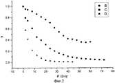
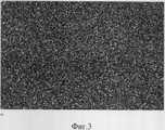
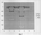
Изобретение поясняется чертежами, на фиг.1 - блок схема устройства для реализации предлагаемого способа; на фиг.2 представлены экспериментальные результаты по изменению коэффициента корреляции поперечного распределения интенсивности рассеянного спекл-поля от изменения частоты для различной толщины тестового образца из фторопласта; на фиг.3 - реально наблюдаемое поперечное распределения интенсивности излучения, прошедшего лазерного излучения через тестовую сильнорассеивающую пластину толщиной 10 мм для фиксированного значения зондирующей лазерной частоты, которое детектируется видеокамерой; на фиг.4 - поперечное распределения интенсивности рассеянного излучения для другого значения частоты лазера, отличающееся на величину девиации 10 ГГц; на фиг.5 - разностная двумерная спекл-картина фиг.3 и фиг.4; на фиг.6 представлена зондируемая сильнорассеивающая структура из фторопласта с внутренней ступенчатой граничной поверхностью, с переменной толщиной от 5 до 20 миллиметров; на фиг.7 - зависимость изменения двумерного коэффициента корреляции от поперечной координаты для различных значений девиации частоты (1-0.1 ГГц; 2-2 ГГц; 3-10 ГГц) при зондировании структуры, изображенной на фиг.6.The invention is illustrated by drawings, in Fig.1 is a block diagram of a device for implementing the proposed method; figure 2 presents the experimental results on the change in the correlation coefficient of the transverse distribution of the intensity of the scattered speckle field from the frequency change for different thicknesses of the test sample of fluoroplastic; figure 3 is a real observed transverse distribution of the intensity of the radiation transmitted by the laser radiation through the test strongly scattering plate with a thickness of 10 mm for a fixed value of the probe laser frequency, which is detected by the camera; figure 4 is a transverse distribution of the intensity of the scattered radiation for a different value of the laser frequency, which differs by a deviation of 10 GHz; figure 5 - differential two-dimensional speckle pattern of figure 3 and figure 4; figure 6 presents the probed strongly diffusing structure of fluoroplastic with an internal stepped boundary surface, with a variable thickness of 5 to 20 millimeters; in Fig.7 - the dependence of the two-dimensional correlation coefficient on the transverse coordinate for various values of the frequency deviation (1-0.1 GHz; 2-2 GHz; 3-10 GHz) when probing the structure depicted in Fig.6.
Способ поясняется чертежом, представленным на фиг.1, где:The method is illustrated by the drawing shown in figure 1, where:
1 - полупроводниковый инжекционный лазер с перестройкой частоты по пилообразному закону с величиной девиации Δν, вызванной изменением тока инжекции;1 - a semiconductor injection laser with frequency tuning according to a sawtooth law with a deviation Δν caused by a change in the injection current;
2 - система двухкоординатного пространственного сканирования лазерного пучка;2 - a system of two-dimensional spatial scanning of a laser beam;
3 - исследуемый объемный оптически неоднородный объект или биоткань;3 - the investigated volume optically heterogeneous object or biological tissue;
4 - цифровая ПЗС видеокамера, регистрирующая поперечное распределение интенсивности прошедшего исследуемый объект (3) рассеянного лазерного излучения;4 - a digital CCD video camera recording the transverse distribution of the intensity of the scattered laser radiation transmitted through the studied object (3);
5 - дифракционный спектрометр типа ДФС или интерферометр Фабри-Перо для измерения частотного сдвига Δν излучения лазера;5 - diffraction spectrometer type DFS or Fabry-Perot interferometer for measuring the frequency shift Δν of laser radiation;
6 - персональный компьютер;6 - personal computer;
В - толщина образца 5 мм;In -
С - толщина образца 10 мм;C -
D - толщина образца 20 мм.D is a sample thickness of 20 mm.
Способ осуществляется следующим образом. В выходном пучке излучения одночастотного лазера (полупроводникового инжекционного лазерного диода 1) частота генерации перестраивается, например, по пилообразному закону с помощью генератора 5 при определенном значением девиации частоты, измеряемой с помощью дифракционного спектрометра или интерферометра типа Фабри-Перо 6, при фиксированном пространственном направлении зондирующего лазерного пучка, определяемом оптоэлектронной системой двухкоординатного поперечного сканера 2, зондирующее излучение направляется на исследуемый оптически неоднородный объект (биоткань) 3, прошедшее рассеянное лазерное излучение, представляющее собой спекл-поле, детектируется с помощью фоточувствительной ПЗС видеоматрицы цифровой видеокамеры 4, полученная последовательность двумерных электронных изображений, пропорциональных поперечному распределению интенсивности рассеянного оптического излучения, фиксируется в компьютере 7, вычисляется коэффициент двумерной корреляции поперечного распределения интенсивности рассеянного спекл-поля от частоты излучения лазера, затем изменяется пространственное положение зондирующего входного лазерного пучка относительно объекта и процедура измерения повторяется.The method is as follows. In the output beam of a single-frequency laser (semiconductor injection laser diode 1), the generation frequency is tuned, for example, according to a sawtooth law using a
В основе предлагаемого метода оптической томографии лежит спекл-фотохромный эффект (Акчурин Г.Г., Акчурин А.Г. Письма в ЖТФ, 2004, Т.30, вып.24, с.56-62), заключающийся в динамике спеклов рассеянного излучения при изменении частоты зондирующего лазерного излучения. При зондировании объемных оптически неоднородных сред в рассеянном оптическом поле вследствие явления интерференции волн возникает определенное спекл-поле, которое детектируется, например, видеоматрицей фотоприемников видеокамеры. Обнаружено, если девиация частоты зондирующего излучения изменяется на величину, соизмеримую с обратным временем средних фазовых задержек рассеянных волн, то коэффициент корреляции интенсивности спекл-поля уменьшается в два раза.The proposed method of optical tomography is based on the speckle-photochromic effect (Akchurin G.G., Akchurin A.G. Letters in ZhTF, 2004, V.30, issue 24, p.56-62), which consists in the dynamics of the speckles of scattered radiation when changing the frequency of the probe laser radiation. When probing bulk optically inhomogeneous media in a scattered optical field due to the phenomenon of wave interference, a certain speckle field arises, which is detected, for example, by the video sensor of the camera’s photodetectors. It was found that if the frequency deviation of the probe radiation changes by a value commensurate with the reciprocal time of the average phase delays of the scattered waves, then the correlation coefficient of the speckle field intensity decreases by half.
В соответствии с формулой изобретения величина девиации частоты зондирующего лазера с перестраиваемой частотой должна быть соизмерима с величиной, обратно пропорциональной величине эффективных временных задержек рассеянных волн в зондируемой объемной оптически неоднородной среде. Величину девиации частоты и, соответственно, величину эффективных временных задержек возможно определить из соотношений, полученных в оптике рассеивающих сред (Исимару А. Распространение и рассеяние волн в случайно-неоднородных средах. М.: Мир,1981. 320 с.; Optical Biomedical Diagnostics.Handbook /ed. V.V.Tuchin. SPIE Press monography V. PM. 107.2003. 1200р.).In accordance with the claims, the frequency deviation of the probing laser with a tunable frequency should be commensurate with the value inversely proportional to the effective time delays of the scattered waves in the probed volume optically inhomogeneous medium. The magnitude of the frequency deviation and, accordingly, the magnitude of the effective time delays can be determined from the relations obtained in the optics of scattering media (Ishimaru A. Propagation and scattering of waves in randomly inhomogeneous media. M: Mir, 1981, 320 p .; Optical Biomedical Diagnostics. Handbook / ed. VVTuchin. SPIE Press monography V. PM. 107.2003. 1200 pp.).
В оптике рассеивающих сред известно, что при зондировании поглощающих и рассеивающих сред ослабление пучка с падающей интенсивностью I0 в условиях однократного рассеяния приближенно описывается с помощью соотношенияIn the optics of scattering media, it is known that when probing absorbing and scattering media, the attenuation of a beam with a decreasing intensity I0 under conditions of a single scattering is approximately described using the relation

μd=μa+μs - коэффициент экстинкции, см-1;μd = μa + μs - extinction coefficient, cm-1 ;
μа - коэффициент поглощения, см-1;μa is the absorption coefficient, cm-1 ;
μs - коэффициент рассеяния, см-1.μs is the scattering coefficient, cm-1 .
Средняя величина свободного пробега однократно рассеянного фотона в среде определяется соотношениемThe mean free path of a single scattered photon in a medium is determined by the relation

В биотканях, которые обычно обладают сильной анизотропией, вводится понятие средней транспортной длины пробега фотонаIn biological tissues, which usually have strong anisotropy, the concept of the average transport mean free path of a photon is introduced

где μs '=μs(1-g) - транспортный коэффициент рассеивания;where μs' = μs (1-g) is the transport dispersion coefficient;
g - параметр анизотропии (средний косинус угла рассеивания); g=0 соответствует изотропному рассеиванию; g=1 полное рассеивание вперед (рассеяние Ми на частицах много больших длины волны).g is the anisotropy parameter (average cosine of the scattering angle); g = 0 corresponds to isotropic scattering; g = 1 full forward scattering (Mie scattering by particles is much longer than the wavelength).
Приближенно учет многократного рассеяния отражается в модернизации соотношения (1) в видеApproximately taking into account multiple scattering is reflected in the modernization of relation (1) in the form

Типичное значение параметра, учитывающего кратность рассеяния для биотканей, соответствует диапазону от 1 до 5, при этом глубина проникновения зондирующего света определяется соотношениемA typical value of a parameter that takes into account the scattering factor for biological tissues corresponds to a range from 1 to 5, while the penetration depth of the probe light is determined by the ratio

Таким образом, в предлагаемом способе при зондировании оптически неоднородных сред оптимальная величина девиации частоты лазера приближенно выбирается из соотношенияThus, in the proposed method, when probing optically inhomogeneous media, the optimal value of the laser frequency deviation is approximately chosen from the relation

где с - скорость света в воздухе;where c is the speed of light in air;
n - средний относительный показатель преломления зондируемой среды.n is the average relative refractive index of the probed medium.
Более точно величину эффективных временных задержек рассеянных волн (средние значения разности хода интерферирующих парциальных составляющих рассеянного поля) возможно оценить лишь с помощью статистических численных методов (Зимняков Д.А., Янг-Те О., Синичкин Ю.П., Акчурин Г.Г., Трифонов В.А. // Опт. и спектр. 2004. Т.97. №2. С.288).More precisely, the value of the effective time delays of scattered waves (average values of the difference in the path of the interfering partial components of the scattered field) can be estimated only using statistical numerical methods (Zimnyakov D.A., Yang-Te O., Sinichkin Yu.P., Akchurin G.G. ., Trifonov V.A. // Opt. And Spectrum. 2004. V.97. No. 2. P.288).
При практическом использовании предлагаемого способа величину девиации частоты зондирующего лазера можно выбрать из соотношения (6), если известна средняя транспортная длина пробега фотона для зондируемой объемной среды (3).In the practical use of the proposed method, the magnitude of the frequency deviation of the probe laser can be selected from relation (6) if the average transport path of the photon for the probed volume medium is known (3).
Если относительно зондируемой среды не известны параметры рассеяния и поглощения, то необходимо применять зондирование с максимально возможной величиной перестройки частоты для используемого лазера, а в ходе последующей обработки рассеянных спекл-полей и вычисления изменения коэффициента корреляции от перестройки частоты для каждой поперечной точки станет возможным оптимизировать диапазон девиации частоты, при котором реализуется максимальная чувствительность к объемной оптической неоднородности.If the scattering and absorption parameters are not known relative to the probed medium, then it is necessary to apply sounding with the maximum possible frequency tuning for the laser used, and during the subsequent processing of the scattered speckle fields and calculating the change in the correlation coefficient from frequency tuning for each transverse point, it will become possible to optimize the range frequency deviation at which the maximum sensitivity to bulk optical inhomogeneity is realized.
Методика эксперимента по наблюдению динамики спеклов заключается в фиксации последовательных поперечных распределений интенсивности рассеянного спекл-поля, измеренных при перестройке частоты излучения лазера и определении двумерного коэффициента корреляции поперечного распределения интенсивности рассеянного спекл-поля, при этом для тонких и малократно рассеивающих структур требуется значительный диапазон изменения частоты в терагерцовой области, а для толстых и сильнорассеивающих - в гигагерцовой.The experiment technique for observing speckle dynamics consists in fixing successive transverse distributions of the intensity of the scattered speckle field, measured by tuning the laser radiation frequency and determining a two-dimensional correlation coefficient of the transverse distribution of the intensity of the scattered speckle field, while a significant frequency range is required for thin and slightly scattering structures in the terahertz region, and for thick and strongly scattering - in the gigahertz.
Экспериментально данный способ был апробирован на тестовых сильнорассеивающих структурах типа фторопласта толщиной от десятков микрон до 2-х сантиметров. Частота излучения одночастотного лазера может перестраиваться на величину ширины линии излучения. Если для газовых лазеров, например для He-Ne (λ=633 нм), она составляет ~1.5 ГГц, то для полупроводниковых или твердотельных лазеров ширина линии излучения и, соответственно, диапазон перестройки частоты может достигать сотен ГГц до десятка терагерц и, соответственно, возможно зондирование очень слаборассеивающих структур с фемто- и пикосекундными задержками рассеянных волн, до нановременных задержек в сильнорассеивающих толстых структурах. Нами в экспериментах использовались полупроводниковый квантово-размерный лазерный диод (λ=650 нм) с перестройкой частоты изменением тока инжекции в пределах десятков и сотен ГГц и твердотельный микролазер YAG:Nd лазер с диодной накачкой и генератором второй гармоники с длиной волны λ=532 нм и диапазоном перестройки частоты порядка 80 ГГц, вызванным изменением длины резонатора. В настоящее время фирма "Toptics" Германия производит одночастотные полупроводниковые лазеры со сканируемой частотой в диапазоне десятков ГГц при пилообразном изменении тока инжекции, которые имеют выходную мощность 80 мВт.Experimentally, this method was tested on test strongly scattering structures such as fluoroplastic with a thickness of tens of microns to 2 centimeters. The radiation frequency of a single-frequency laser can be tuned to the value of the radiation line width. If for gas lasers, for example, for He-Ne (λ = 633 nm), it is ~ 1.5 GHz, then for semiconductor or solid-state lasers, the emission line width and, accordingly, the frequency tuning range can reach hundreds of GHz up to a dozen terahertz and, accordingly, probing of very weakly scattering structures with femto- and picosecond delays of scattered waves is possible, up to unstoppable delays in strongly scattering thick structures. In our experiments, we used a semiconductor quantum-well laser diode (λ = 650 nm) with frequency tuning by changing the injection current within tens and hundreds of GHz and a YAG solid-state microlaser: an Nd diode-pumped laser with a second harmonic generator with a wavelength of λ = 532 nm and frequency tuning range of the order of 80 GHz caused by a change in the length of the resonator. Currently, the company "Toptics" Germany produces single-frequency semiconductor lasers with a scanned frequency in the range of tens of GHz with a sawtooth change in the injection current, which have an output power of 80 mW.
Экспериментально данный способ был апробирован на тестовых сильнорассеивающих структурах типа фторопласта толщиной от десятков микрон до 2-х сантиметров. Диагностические возможности предлагаемого способа показаны на фиг.7, где представлена одна из экспериментальных реализаций изменения двумерного коэффициента корреляции при поперечном сканировании лазерного пучка для различных величин девиации частоты. При величине девиации, равной 100 МГц (фиг.7. кривая 1), изменение коэффициент корреляции от поперечной координаты практически не происходит, но уже при величине девиации в 2 ГГц (фиг.7. кривая 2) изменение коэффициента корреляции позволяет однозначно идентифицировать различную толщину зондируемой структуры (фиг.6). Чувствительность метода зависит от величины девиации частоты (сравнение кривой 2 и кривой 3 на фиг.7, для которой величина девиации достигает 10 ГГц).Experimentally, this method was tested on test strongly scattering structures such as fluoroplastic with a thickness of tens of microns to 2 centimeters. The diagnostic capabilities of the proposed method are shown in Fig. 7, which shows one of the experimental implementations of a change in the two-dimensional correlation coefficient during transverse scanning of a laser beam for different values of the frequency deviation. With a deviation value of 100 MHz (Fig. 7, curve 1), a change in the correlation coefficient from the transverse coordinate practically does not occur, but already with a deviation of 2 GHz (Fig. 7, curve 2), a change in the correlation coefficient allows one to unambiguously identify the different thickness probed structure (Fig.6). The sensitivity of the method depends on the magnitude of the frequency deviation (comparison of
По сравнению с прототипом предлагаемый способ позволяет действительно увеличить глубину зондирования. Если в прототипе глубина зондирования сильнорассеивающих сред и биотканей не превышает несколько миллиметров, то в предлагаемом способе глубина зондирования составляет не менее 2-х сантиметров при уровне оптической мощности не более милливатта. В прототипе при зондировании рассеивающих сред оптическим излучением с управляемой когерентностью используется суперлюминесцентный светодиод или полупроводниковый лазер в допороговом режиме генерации. Максимальная оптическая мощность суперлюминесцентных светодиодов или лазеров до и вблизи порога не превышает одного милливатта, в то время как существующие в настоящее время одночастотные полупроводниковые лазеры со сканируемой частотой в диапазоне десятков ГГц при изменении тока инжекции имеют выходную мощность 80 мВт (например, фирма "Toptics", Германия), которые могут быть положены в основу предлагаемого способа.Compared with the prototype, the proposed method can really increase the sounding depth. If in the prototype the sounding depth of strongly scattering media and biological tissues does not exceed several millimeters, then in the proposed method, the sounding depth is at least 2 centimeters with an optical power level of not more than milliwatts. In the prototype, when probing scattering media with optical radiation with controlled coherence, a superluminescent LED or a semiconductor laser is used in the subthreshold generation mode. The maximum optical power of superluminescent LEDs or lasers before and near the threshold does not exceed one milliwatt, while the currently existing single-frequency semiconductor lasers with a scanned frequency in the range of tens of GHz have an output power of 80 mW when changing the injection current (for example, Toptics , Germany), which can be the basis of the proposed method.
Глубина зондирования лазерным излучением зависит от коэффициента поглощения биоткани, поэтому для увеличения динамического диапазона по глубине длина волны лазера выбирается из соображений минимального поглощения. В оптике биотканей известно (Тучин В.В. Лазеры и волоконная оптика в биомедицинских исследованиях. Саратов, СГУ.1998), что "окно прозрачности" лежит в ближнем ИК диапазоне от 0.7 до 1.5 микрон, что и должно определять выбор длины волны зондирующего лазера. Кроме того, такой одночастотный лазер должен обладать широким диапазоном перестройки частоты и для конкретной реализации этих требований наиболее подходят недорогие инжекционные полупроводниковые лазеры.The depth of sounding by laser radiation depends on the absorption coefficient of biological tissue, therefore, to increase the dynamic range in depth, the laser wavelength is selected from the considerations of minimal absorption. It is known in optics of biological tissues (Tuchin VV Lasers and fiber optics in biomedical research. Saratov, SSU. 1998) that the “transparency window” lies in the near IR range from 0.7 to 1.5 microns, which should determine the choice of the wavelength of the probe laser . In addition, such a single-frequency laser should have a wide frequency tuning range, and low-cost injection semiconductor lasers are most suitable for the specific implementation of these requirements.
Claims (2)
Translated fromRussianPriority Applications (1)
| Application Number | Priority Date | Filing Date | Title |
|---|---|---|---|
| RU2005140173/14ARU2303393C1 (en) | 2005-12-23 | 2005-12-23 | Method for applying optical coherent tomography |
Applications Claiming Priority (1)
| Application Number | Priority Date | Filing Date | Title |
|---|---|---|---|
| RU2005140173/14ARU2303393C1 (en) | 2005-12-23 | 2005-12-23 | Method for applying optical coherent tomography |
Publications (1)
| Publication Number | Publication Date |
|---|---|
| RU2303393C1true RU2303393C1 (en) | 2007-07-27 |
Family
ID=38431599
Family Applications (1)
| Application Number | Title | Priority Date | Filing Date |
|---|---|---|---|
| RU2005140173/14ARU2303393C1 (en) | 2005-12-23 | 2005-12-23 | Method for applying optical coherent tomography |
Country Status (1)
| Country | Link |
|---|---|
| RU (1) | RU2303393C1 (en) |
Cited By (3)
| Publication number | Priority date | Publication date | Assignee | Title |
|---|---|---|---|---|
| RU2403559C1 (en)* | 2009-06-02 | 2010-11-10 | Государственное образовательное учреждение высшего профессионального образования "Саратовский государственный университет им. Н.Г. Чернышевского" | Diagnostic method of internal images in art pictures |
| RU2407426C1 (en)* | 2009-07-30 | 2010-12-27 | Государственное учреждение Московский областной научно-исследовательский клинический институт им. М.Ф. Владимирского (МОНИКИ им. М.Ф. Владимирского) | Method of determining size and depth of anatomo-morphological structures position in live biological tissue during its examination by means of optical coherence tomography |
| RU2515189C2 (en)* | 2008-08-05 | 2014-05-10 | Коммиссариат Ал'Энержи Атомик Э Оз Энержи Альтернатив | Method of contactless measurement of density of porous material using measurement of coefficient of material refraction by means of optical coherent tomography |
Citations (3)
| Publication number | Priority date | Publication date | Assignee | Title |
|---|---|---|---|---|
| RU2102008C1 (en)* | 1995-08-22 | 1998-01-20 | Брий М. Корана | Device for diagnosing dental pulpar chamber state |
| US6549801B1 (en)* | 1998-06-11 | 2003-04-15 | The Regents Of The University Of California | Phase-resolved optical coherence tomography and optical doppler tomography for imaging fluid flow in tissue with fast scanning speed and high velocity sensitivity |
| WO2004088361A2 (en)* | 2003-03-31 | 2004-10-14 | The General Hospital Corporation | Speckle reduction in optical coherence tomography by path length encoded angular compounding |
- 2005
- 2005-12-23RURU2005140173/14Apatent/RU2303393C1/ennot_activeIP Right Cessation
Patent Citations (3)
| Publication number | Priority date | Publication date | Assignee | Title |
|---|---|---|---|---|
| RU2102008C1 (en)* | 1995-08-22 | 1998-01-20 | Брий М. Корана | Device for diagnosing dental pulpar chamber state |
| US6549801B1 (en)* | 1998-06-11 | 2003-04-15 | The Regents Of The University Of California | Phase-resolved optical coherence tomography and optical doppler tomography for imaging fluid flow in tissue with fast scanning speed and high velocity sensitivity |
| WO2004088361A2 (en)* | 2003-03-31 | 2004-10-14 | The General Hospital Corporation | Speckle reduction in optical coherence tomography by path length encoded angular compounding |
Non-Patent Citations (1)
| Title |
|---|
| ЗИМНЯКОВ Д.А. и др. Оптика и спектрография, 2004, т.97, №2, с.288-293. АКЧУРИН Г.Г. и др. Фотохромная когерентная спекл-диагностика объемных рассеивающих сред и оптических световодов лазерами с перестраиваемой частотой. Письма в ЖТФ, 2004, т.30, вып.24, с.56-62.* |
Cited By (3)
| Publication number | Priority date | Publication date | Assignee | Title |
|---|---|---|---|---|
| RU2515189C2 (en)* | 2008-08-05 | 2014-05-10 | Коммиссариат Ал'Энержи Атомик Э Оз Энержи Альтернатив | Method of contactless measurement of density of porous material using measurement of coefficient of material refraction by means of optical coherent tomography |
| RU2403559C1 (en)* | 2009-06-02 | 2010-11-10 | Государственное образовательное учреждение высшего профессионального образования "Саратовский государственный университет им. Н.Г. Чернышевского" | Diagnostic method of internal images in art pictures |
| RU2407426C1 (en)* | 2009-07-30 | 2010-12-27 | Государственное учреждение Московский областной научно-исследовательский клинический институт им. М.Ф. Владимирского (МОНИКИ им. М.Ф. Владимирского) | Method of determining size and depth of anatomo-morphological structures position in live biological tissue during its examination by means of optical coherence tomography |
Similar Documents
| Publication | Publication Date | Title |
|---|---|---|
| KR101269455B1 (en) | System and method for optical coherence imaging | |
| US8357915B2 (en) | Method and device for measuring optical characteristics of an object | |
| US9116111B2 (en) | Acoustic signal receiving apparatus and imaging apparatus | |
| US7777891B2 (en) | Elasticity and viscosity measuring apparatus | |
| USRE46412E1 (en) | Methods and systems for performing angle-resolved Fourier-domain optical coherence tomography | |
| US6236871B1 (en) | Absorption information measuring method and apparatus of scattering medium | |
| US8364414B2 (en) | Apparatus and method for processing biological information | |
| JP3660761B2 (en) | Method and apparatus for measuring absorption information of scatterers | |
| US6847456B2 (en) | Methods and systems using field-based light scattering spectroscopy | |
| CN104224113B (en) | Object information acquisition device and the method for control object information acquisition device | |
| US8280494B2 (en) | Apparatus and method to measure a spectroscopic characteristic in an object | |
| Pleitez et al. | Photothermal deflectometry enhanced by total internal reflection enables non-invasive glucose monitoring in human epidermis | |
| US20140153083A1 (en) | Rin reduced optical source for optical coherence tomography | |
| JP2000046729A (en) | Apparatus and method for high-speed measurement of optical topographic image by using wavelength dispersion | |
| US7010339B2 (en) | Hybrid lidar-radar for medical diagnostics | |
| JP3688608B2 (en) | Optical coherence tomographic image measuring device with spectroscopic function | |
| JPWO2016056522A1 (en) | Optical response measuring apparatus and optical response measuring method | |
| JP4018799B2 (en) | Method and apparatus for measuring concentration of absorption component of scattering medium | |
| Trivedi et al. | Temporal analysis of reflected optical signals for short pulse laser interaction with nonhomogeneous tissue phantoms | |
| RU2303393C1 (en) | Method for applying optical coherent tomography | |
| JPH10246697A (en) | Optical inspection method and optical inspection device | |
| Corral et al. | Tissue characterization with ballistic photons: counting scattering and/or absorption centres | |
| JP3878943B2 (en) | Method and apparatus for measuring absorption information of scatterers | |
| Makino | Non-destructive observation of morphological and structural alterations in industrial materials based on near-infrared spectral-domain optical coherence tomography | |
| JP3878942B2 (en) | Method and apparatus for measuring absorption information of scatterers |
Legal Events
| Date | Code | Title | Description |
|---|---|---|---|
| MM4A | The patent is invalid due to non-payment of fees | Effective date:20131224 |