RU2295361C2 - System for performing medical product infusion and carbon dioxide monitoring - Google Patents
System for performing medical product infusion and carbon dioxide monitoringDownload PDFInfo
- Publication number
- RU2295361C2 RU2295361C2RU2004120786/14ARU2004120786ARU2295361C2RU 2295361 C2RU2295361 C2RU 2295361C2RU 2004120786/14 ARU2004120786/14 ARU 2004120786/14ARU 2004120786 ARU2004120786 ARU 2004120786ARU 2295361 C2RU2295361 C2RU 2295361C2
- Authority
- RU
- Russia
- Prior art keywords
- patient
- medicinal
- pump
- unit
- carbon dioxide
- Prior art date
Links
- CURLTUGMZLYLDI-UHFFFAOYSA-NCarbon dioxideChemical compoundO=C=OCURLTUGMZLYLDI-UHFFFAOYSA-N0.000titleclaimsabstractdescription223
- 238000001802infusionMethods0.000titleclaimsabstractdescription123
- 238000012544monitoring processMethods0.000titleclaimsabstractdescription117
- 229910002092carbon dioxideInorganic materials0.000titleclaimsabstractdescription111
- 239000001569carbon dioxideSubstances0.000titleclaimsabstractdescription111
- 229940127554medical productDrugs0.000title1
- 239000003814drugSubstances0.000claimsabstractdescription45
- 238000004891communicationMethods0.000claimsabstractdescription24
- 239000007788liquidSubstances0.000claimsabstract5
- 239000012530fluidSubstances0.000claimsdescription91
- QVGXLLKOCUKJST-UHFFFAOYSA-Natomic oxygenChemical compound[O]QVGXLLKOCUKJST-UHFFFAOYSA-N0.000claimsdescription34
- 229910052760oxygenInorganic materials0.000claimsdescription34
- 239000001301oxygenSubstances0.000claimsdescription34
- 229940124583pain medicationDrugs0.000claimsdescription28
- 239000008280bloodSubstances0.000claimsdescription25
- 210000004369bloodAnatomy0.000claimsdescription25
- 230000008859changeEffects0.000claimsdescription21
- 230000036387respiratory rateEffects0.000claimsdescription21
- 238000000034methodMethods0.000claimsdescription19
- 230000004044responseEffects0.000claimsdescription16
- 229940035674anestheticsDrugs0.000claimsdescription14
- 239000003193general anesthetic agentSubstances0.000claimsdescription14
- 238000002496oximetryMethods0.000claimsdescription14
- 230000003444anaesthetic effectEffects0.000claimsdescription13
- 230000007246mechanismEffects0.000claimsdescription13
- 238000005086pumpingMethods0.000claimsdescription13
- 230000029058respiratory gaseous exchangeEffects0.000claimsdescription10
- 230000009471actionEffects0.000claimsdescription6
- 230000000202analgesic effectEffects0.000claimsdescription4
- 238000012790confirmationMethods0.000claimsdescription2
- 230000003993interactionEffects0.000claimsdescription2
- 238000006213oxygenation reactionMethods0.000claimsdescription2
- 229940124597therapeutic agentDrugs0.000claimsdescription2
- 239000007924injectionSubstances0.000claims7
- 238000002347injectionMethods0.000claims7
- 238000001990intravenous administrationMethods0.000claims2
- 230000001276controlling effectEffects0.000claims1
- 230000001105regulatory effectEffects0.000claims1
- 229940079593drugDrugs0.000abstractdescription41
- 230000000694effectsEffects0.000abstractdescription4
- 230000000007visual effectEffects0.000abstractdescription2
- 230000004907fluxEffects0.000abstract2
- 238000010992refluxMethods0.000abstract2
- 206010002091AnaesthesiaDiseases0.000abstract1
- 230000037005anaesthesiaEffects0.000abstract1
- 239000000126substanceSubstances0.000abstract1
- 238000010977unit operationMethods0.000abstract1
- 230000006870functionEffects0.000description33
- 238000002106pulse oximetryMethods0.000description18
- 208000004756Respiratory InsufficiencyDiseases0.000description9
- 206010038678Respiratory depressionDiseases0.000description9
- 230000003533narcotic effectEffects0.000description9
- 238000003825pressingMethods0.000description9
- 238000004458analytical methodMethods0.000description7
- 210000003169central nervous systemAnatomy0.000description7
- 210000002345respiratory systemAnatomy0.000description7
- 238000012377drug deliveryMethods0.000description6
- 230000000472traumatic effectEffects0.000description5
- 238000010586diagramMethods0.000description4
- 230000036407painEffects0.000description4
- 230000036592analgesiaEffects0.000description3
- 230000034994deathEffects0.000description3
- 231100000517deathToxicity0.000description3
- 238000005259measurementMethods0.000description3
- 239000006187pillSubstances0.000description3
- 230000005855radiationEffects0.000description3
- 230000000241respiratory effectEffects0.000description3
- 229940125723sedative agentDrugs0.000description3
- 239000000932sedative agentSubstances0.000description3
- 102000001554HemoglobinsHuman genes0.000description2
- 108010054147HemoglobinsProteins0.000description2
- 208000029028brain injuryDiseases0.000description2
- 230000000747cardiac effectEffects0.000description2
- 238000001647drug administrationMethods0.000description2
- 230000009931harmful effectEffects0.000description2
- UZHSEJADLWPNLE-GRGSLBFTSA-NnaloxoneChemical compoundO=C([C@@H]1O2)CC[C@@]3(O)[C@H]4CC5=CC=C(O)C2=C5[C@@]13CCN4CC=CUZHSEJADLWPNLE-GRGSLBFTSA-N0.000description2
- 239000003887narcotic antagonistSubstances0.000description2
- 230000003287optical effectEffects0.000description2
- -1painkillersSubstances0.000description2
- 230000011664signalingEffects0.000description2
- 230000001225therapeutic effectEffects0.000description2
- 238000012935AveragingMethods0.000description1
- 208000007204Brain deathDiseases0.000description1
- 208000020401Depressive diseaseDiseases0.000description1
- 208000032368Device malfunctionDiseases0.000description1
- 238000004566IR spectroscopyMethods0.000description1
- 206010061218InflammationDiseases0.000description1
- 238000001069Raman spectroscopyMethods0.000description1
- 206010041349SomnolenceDiseases0.000description1
- 208000027418Wounds and injuryDiseases0.000description1
- 230000003213activating effectEffects0.000description1
- 230000004913activationEffects0.000description1
- 238000005085air analysisMethods0.000description1
- 239000003242anti bacterial agentSubstances0.000description1
- 229940088710antibiotic agentDrugs0.000description1
- 239000002246antineoplastic agentSubstances0.000description1
- 238000013459approachMethods0.000description1
- 230000008901benefitEffects0.000description1
- 230000000903blocking effectEffects0.000description1
- 230000036772blood pressureEffects0.000description1
- 210000004204blood vesselAnatomy0.000description1
- 210000004556brainAnatomy0.000description1
- 230000008344brain blood flowEffects0.000description1
- 238000004364calculation methodMethods0.000description1
- 238000005266castingMethods0.000description1
- 239000002131composite materialSubstances0.000description1
- 239000000599controlled substanceSubstances0.000description1
- 229940127089cytotoxic agentDrugs0.000description1
- 230000006378damageEffects0.000description1
- 238000013479data entryMethods0.000description1
- 230000001419dependent effectEffects0.000description1
- 230000009977dual effectEffects0.000description1
- 210000000624ear auricleAnatomy0.000description1
- 230000000763evoking effectEffects0.000description1
- 230000036541healthEffects0.000description1
- 230000004054inflammatory processEffects0.000description1
- 208000014674injuryDiseases0.000description1
- 238000002372labellingMethods0.000description1
- 239000000463materialSubstances0.000description1
- 238000002483medicationMethods0.000description1
- QSHDDOUJBYECFT-UHFFFAOYSA-NmercuryChemical compound[Hg]QSHDDOUJBYECFT-UHFFFAOYSA-N0.000description1
- 229910052753mercuryInorganic materials0.000description1
- 238000012986modificationMethods0.000description1
- 230000004048modificationEffects0.000description1
- 229960004127naloxoneDrugs0.000description1
- 229940065778narcanDrugs0.000description1
- 238000011017operating methodMethods0.000description1
- 238000004867photoacoustic spectroscopyMethods0.000description1
- 230000008569processEffects0.000description1
- 238000011084recoveryMethods0.000description1
- 229920006395saturated elastomerPolymers0.000description1
- 238000004611spectroscopical analysisMethods0.000description1
- 230000001360synchronised effectEffects0.000description1
- 230000001960triggered effectEffects0.000description1
- 238000012795verificationMethods0.000description1
Images


Classifications
- A—HUMAN NECESSITIES
- A61—MEDICAL OR VETERINARY SCIENCE; HYGIENE
- A61M—DEVICES FOR INTRODUCING MEDIA INTO, OR ONTO, THE BODY; DEVICES FOR TRANSDUCING BODY MEDIA OR FOR TAKING MEDIA FROM THE BODY; DEVICES FOR PRODUCING OR ENDING SLEEP OR STUPOR
- A61M5/00—Devices for bringing media into the body in a subcutaneous, intra-vascular or intramuscular way; Accessories therefor, e.g. filling or cleaning devices, arm-rests
- A61M5/14—Infusion devices, e.g. infusing by gravity; Blood infusion; Accessories therefor
- A61M5/168—Means for controlling media flow to the body or for metering media to the body, e.g. drip meters, counters ; Monitoring media flow to the body
- A61M5/172—Means for controlling media flow to the body or for metering media to the body, e.g. drip meters, counters ; Monitoring media flow to the body electrical or electronic
- A61M5/1723—Means for controlling media flow to the body or for metering media to the body, e.g. drip meters, counters ; Monitoring media flow to the body electrical or electronic using feedback of body parameters, e.g. blood-sugar, pressure
- G—PHYSICS
- G16—INFORMATION AND COMMUNICATION TECHNOLOGY [ICT] SPECIALLY ADAPTED FOR SPECIFIC APPLICATION FIELDS
- G16H—HEALTHCARE INFORMATICS, i.e. INFORMATION AND COMMUNICATION TECHNOLOGY [ICT] SPECIALLY ADAPTED FOR THE HANDLING OR PROCESSING OF MEDICAL OR HEALTHCARE DATA
- G16H20/00—ICT specially adapted for therapies or health-improving plans, e.g. for handling prescriptions, for steering therapy or for monitoring patient compliance
- G16H20/10—ICT specially adapted for therapies or health-improving plans, e.g. for handling prescriptions, for steering therapy or for monitoring patient compliance relating to drugs or medications, e.g. for ensuring correct administration to patients
- G16H20/17—ICT specially adapted for therapies or health-improving plans, e.g. for handling prescriptions, for steering therapy or for monitoring patient compliance relating to drugs or medications, e.g. for ensuring correct administration to patients delivered via infusion or injection
- A—HUMAN NECESSITIES
- A61—MEDICAL OR VETERINARY SCIENCE; HYGIENE
- A61M—DEVICES FOR INTRODUCING MEDIA INTO, OR ONTO, THE BODY; DEVICES FOR TRANSDUCING BODY MEDIA OR FOR TAKING MEDIA FROM THE BODY; DEVICES FOR PRODUCING OR ENDING SLEEP OR STUPOR
- A61M5/00—Devices for bringing media into the body in a subcutaneous, intra-vascular or intramuscular way; Accessories therefor, e.g. filling or cleaning devices, arm-rests
- A61M5/14—Infusion devices, e.g. infusing by gravity; Blood infusion; Accessories therefor
- A61M2005/1401—Functional features
- A61M2005/1405—Patient controlled analgesia [PCA]
- A—HUMAN NECESSITIES
- A61—MEDICAL OR VETERINARY SCIENCE; HYGIENE
- A61M—DEVICES FOR INTRODUCING MEDIA INTO, OR ONTO, THE BODY; DEVICES FOR TRANSDUCING BODY MEDIA OR FOR TAKING MEDIA FROM THE BODY; DEVICES FOR PRODUCING OR ENDING SLEEP OR STUPOR
- A61M2202/00—Special media to be introduced, removed or treated
- A61M2202/04—Liquids
- A61M2202/0468—Liquids non-physiological
- A61M2202/048—Anaesthetics
- A—HUMAN NECESSITIES
- A61—MEDICAL OR VETERINARY SCIENCE; HYGIENE
- A61M—DEVICES FOR INTRODUCING MEDIA INTO, OR ONTO, THE BODY; DEVICES FOR TRANSDUCING BODY MEDIA OR FOR TAKING MEDIA FROM THE BODY; DEVICES FOR PRODUCING OR ENDING SLEEP OR STUPOR
- A61M2205/00—General characteristics of the apparatus
- A61M2205/60—General characteristics of the apparatus with identification means
- A61M2205/6054—Magnetic identification systems
- A—HUMAN NECESSITIES
- A61—MEDICAL OR VETERINARY SCIENCE; HYGIENE
- A61M—DEVICES FOR INTRODUCING MEDIA INTO, OR ONTO, THE BODY; DEVICES FOR TRANSDUCING BODY MEDIA OR FOR TAKING MEDIA FROM THE BODY; DEVICES FOR PRODUCING OR ENDING SLEEP OR STUPOR
- A61M2230/00—Measuring parameters of the user
- A61M2230/20—Blood composition characteristics
- A61M2230/205—Blood composition characteristics partial oxygen pressure (P-O2)
- A—HUMAN NECESSITIES
- A61—MEDICAL OR VETERINARY SCIENCE; HYGIENE
- A61M—DEVICES FOR INTRODUCING MEDIA INTO, OR ONTO, THE BODY; DEVICES FOR TRANSDUCING BODY MEDIA OR FOR TAKING MEDIA FROM THE BODY; DEVICES FOR PRODUCING OR ENDING SLEEP OR STUPOR
- A61M2230/00—Measuring parameters of the user
- A61M2230/40—Respiratory characteristics
- A61M2230/43—Composition of exhalation
- A61M2230/432—Composition of exhalation partial CO2 pressure (P-CO2)
- A—HUMAN NECESSITIES
- A61—MEDICAL OR VETERINARY SCIENCE; HYGIENE
- A61M—DEVICES FOR INTRODUCING MEDIA INTO, OR ONTO, THE BODY; DEVICES FOR TRANSDUCING BODY MEDIA OR FOR TAKING MEDIA FROM THE BODY; DEVICES FOR PRODUCING OR ENDING SLEEP OR STUPOR
- A61M5/00—Devices for bringing media into the body in a subcutaneous, intra-vascular or intramuscular way; Accessories therefor, e.g. filling or cleaning devices, arm-rests
- A61M5/14—Infusion devices, e.g. infusing by gravity; Blood infusion; Accessories therefor
- A61M5/142—Pressure infusion, e.g. using pumps
- G—PHYSICS
- G16—INFORMATION AND COMMUNICATION TECHNOLOGY [ICT] SPECIALLY ADAPTED FOR SPECIFIC APPLICATION FIELDS
- G16H—HEALTHCARE INFORMATICS, i.e. INFORMATION AND COMMUNICATION TECHNOLOGY [ICT] SPECIALLY ADAPTED FOR THE HANDLING OR PROCESSING OF MEDICAL OR HEALTHCARE DATA
- G16H70/00—ICT specially adapted for the handling or processing of medical references
- G16H70/40—ICT specially adapted for the handling or processing of medical references relating to drugs, e.g. their side effects or intended usage
Landscapes
- Health & Medical Sciences (AREA)
- Engineering & Computer Science (AREA)
- Public Health (AREA)
- General Health & Medical Sciences (AREA)
- Biomedical Technology (AREA)
- Chemical & Material Sciences (AREA)
- Heart & Thoracic Surgery (AREA)
- Hematology (AREA)
- Life Sciences & Earth Sciences (AREA)
- Animal Behavior & Ethology (AREA)
- Vascular Medicine (AREA)
- Diabetes (AREA)
- Veterinary Medicine (AREA)
- Anesthesiology (AREA)
- Bioinformatics & Cheminformatics (AREA)
- Medicinal Chemistry (AREA)
- Epidemiology (AREA)
- Medical Informatics (AREA)
- Primary Health Care (AREA)
- Infusion, Injection, And Reservoir Apparatuses (AREA)
- Medicines Containing Antibodies Or Antigens For Use As Internal Diagnostic Agents (AREA)
- Measurement Of The Respiration, Hearing Ability, Form, And Blood Characteristics Of Living Organisms (AREA)
- Measuring Pulse, Heart Rate, Blood Pressure Or Blood Flow (AREA)
Abstract
Description
Translated fromRussianНастоящее изобретение вообще относится к системе контроля за пациентом, в которой лекарственная медицинская жидкость вводится пациенту, в то время как пациент контролируется по его физическому состоянию, и более конкретно, к системе и способу, в которых лекарственная медицинская жидкость водится пациенту, в то время как выдыхаемый пациентом воздух контролируется по конкретному компоненту.The present invention generally relates to a patient monitoring system in which medicinal fluid is administered to a patient, while the patient is controlled by his physical condition, and more particularly, to a system and method in which medicinal fluid is administered to the patient, while air exhaled by the patient is controlled by a specific component.
Программируемые инфузионные системы обычно используются в области медицины для того, чтобы обеспечивать наличие широкого диапазона лекарственных средств и жидкостей для пациентов в различных учреждениях. Например, шприцевые насосы, насосы с большой дозировкой (здесь обозначенные как "LVP") и регуляторы потоков используются в больницах, клиниках и в клинических учреждениях для того, чтобы доставлять лекарственные медицинские жидкости типа парентеральных жидкостей, антибиотиков, химиотерапевтических средств, анестезирующих средств, обезболивающих средств, снотворных средств или других лекарств. Доступны одноканальные или многоканальные системы, и различные системы имеют различные уровни сложности, включая автоматические калькуляторы для лекарственных средств, библиотеки лекарственных средств и комплексные протоколы поставок. Тем не менее, другой тип системы доставки лекарственного средства представляет собой насос для контролируемого обезболивания пациента (здесь обозначенный как "РСА"). При наличии насоса для контролируемого обезболивания контролируется прием пациентом обезболивающих наркотических средств, так как пациент обычно находится в наилучшей позиции для того, чтобы определить потребность в дополнительном контролировании боли. Обезболивающее средство для контролируемого пациента обычно принимается им посредством инфузионного средства автономного типа, специально предназначенного только для использования обезболивающего средства для контролируемого пациента. Примеры устройств для контролируемого приема обезболивающего средства пациентом раскрыты в патенте США №5069668, автором изобретения по которому является Боудмен, и в патенте США №5232448, автором изобретения по которому является Здэб.Programmable infusion systems are commonly used in the medical field to provide a wide range of drugs and fluids for patients in various settings. For example, syringe pumps, high-dosage pumps (hereinafter referred to as “LVPs”) and flow controllers are used in hospitals, clinics, and clinical settings to deliver medicinal fluids such as parenteral fluids, antibiotics, chemotherapeutic agents, anesthetics, painkillers drugs, sleeping pills or other medicines. Single-channel or multi-channel systems are available, and various systems have varying difficulty levels, including automatic drug calculators, drug libraries, and comprehensive delivery protocols. However, another type of drug delivery system is a patient controlled pain relief pump (hereinafter referred to as "PCA"). With a pump for controlled analgesia, the patient is controlled to take painkillers, as the patient is usually in the best position to determine the need for additional pain control. The analgesic for a controlled patient is usually taken by an autonomous type of infusion, specifically designed only for the use of an analgesic for a controlled patient. Examples of devices for the controlled administration of pain medication by a patient are disclosed in US Pat. No. 5,069,668, the inventor of which is Bowman, and US Pat. No. 5,232,448, the author of which is Zdeb.
Независимо от типа используемой насосной системы серьезный побочный эффект при приеме лекарств, особенно анестезирующих, обезболивающих или снотворных средств, может проявляться в депрессии центральной нервной системы и в угнетении дыхания, которое может приводить к серьезному мозговому травмированию или к смерти. Например, вливание анестезирующих, обезболивающих или седативных средств при использовании шприцевого насоса или насоса с большой дозировкой (LVP) требует осторожного наблюдения обученным медицинским персоналом для того, чтобы избежать передозирование. Даже при наличии инфузионных систем, характеризующихся признаками наличия сложного автоматического программирования и вычисления и разработанных для того, чтобы свести к минимуму ошибки лечения, пациенты нередко испытывают угнетение дыхания или другие вредные эффекты во время приема наркотических обезболивающих или седативных средств в процессе проведения медицинских процедур в условиях стационарного или амбулаторного лечения. Даже в случае применения насоса РСА для обезболивания контролируемого пациента, когда передозировки типично предотвращаются впаданием пациента в сонное состояние и его неспособностью к тому, чтобы привести в действие кнопку доставки, имелись случаи депрессии дыхательной системы и центральной нервной системы и даже случаи смерти, связанной с приемом средств РСА для обезболивания, контролируемого пациента. Причины заключаются в клинических ошибках в программировании устройства для приема средства РСА для обезболивания контролируемого пациента, в ошибках при смешивании или в маркировании обезболивающих средств, в сбое устройства и даже в не в меру старательных родственниках, которые заставляют принимать чрезмерные дозы обезболивающих средств, нажимая на кнопку кабеля запроса дозы для пациента.Regardless of the type of pump system used, a serious side effect when taking medications, especially anesthetics, painkillers or sleeping pills, can be manifested in central nervous system depression and respiratory depression, which can lead to serious brain injury or death. For example, infusion of anesthetics, painkillers, or sedatives using a syringe pump or high-dose pump (LVP) requires careful observation by trained medical personnel in order to avoid overdosing. Even if there are infusion systems that are characterized by complex automated programming and calculation and are designed to minimize treatment errors, patients often experience respiratory depression or other harmful effects while taking narcotic painkillers or sedatives during medical procedures under conditions inpatient or outpatient treatment. Even when using a PCA pump to anesthetize a controlled patient, when overdoses are typically prevented by the patient falling into a sleepy state and his inability to activate the delivery button, there have been cases of depression of the respiratory system and central nervous system and even deaths associated with administration PCA for pain control, patient-controlled. The reasons are clinical errors in programming a device for receiving PCA for pain control of a controlled patient, errors in mixing or labeling painkillers, device malfunction, and even overly diligent relatives who force them to take excessive doses of painkillers by pressing the button dose request cable for the patient.
Из-за потенциальных опасностей передозировки наркотических обезболивающих средств наркотические антагонисты типа налоксон (Narcan™) широко доступны и обычно используются в больницах для реверсирования депрессии дыхательной системы и центральной нервной системы. Однако эффективность таких наркотических антагонистов чрезмерно зависит от распознавания подсказки и лечения депрессии дыхательной системы и центральной нервной системы, поскольку такая депрессия может вызывать мозговой травматизм или даже смерть из-за недостатка кислорода. Таким образом, депрессия дыхательной и центральной нервной систем должна быть обнаружена и быстро устраняться, для того чтобы гарантировать с более высокой вероятностью успешное восстановление здоровья. Поэтому было бы желательно контролировать фактическое физическое состояние пациента для того, чтобы обнаруживать депрессию дыхательной и центральной нервной систем таким образом, чтобы могли быть осуществлены немедленные лечебные мероприятия.Because of the potential dangers of overdosing on narcotic painkillers, narcotic antagonists such as naloxone (Narcan™ ) are widely available and are commonly used in hospitals to reverse the depression of the respiratory system and central nervous system. However, the effectiveness of such narcotic antagonists is overly dependent on recognition of the prompt and treatment of depression of the respiratory system and central nervous system, since such depression can cause brain injury or even death due to lack of oxygen. Thus, depression of the respiratory and central nervous systems must be detected and quickly eliminated in order to guarantee a high probability of successful recovery of health. Therefore, it would be desirable to monitor the actual physical condition of the patient in order to detect depression of the respiratory and central nervous systems so that immediate therapeutic measures can be taken.
Для обнаружения потенциального угнетения дыхания, связанного с приемом наркотических обезболивающих, седативных или анестезирующих средств, особенно желательной и полезной является система, которая указывает на состояние дыхательной системы пациента и на его кардиальное состояние без потребности вмешательства с целью измерения или выполнения отбора пробы крови пациента. Нетравматичная (неинвазивная) импульсная оксиметрия является одним таким способом, который использовался для контролирования насыщения крови пациента кислородом и для контролирования частоты дыхания пациента. Сочетание насыщения крови кислородом и частоты дыхания может быть важным индикатором общего дыхательного и кардиального состояния.To detect potential respiratory depression associated with taking narcotic painkillers, sedatives, or anesthetics, a system that indicates the patient’s respiratory system and cardiac state without the need for intervention to measure or take a patient’s blood sample is particularly desirable and useful. Non-traumatic (non-invasive) pulse oximetry is one such method that has been used to control the patient’s blood oxygen saturation and to control the patient’s respiratory rate. The combination of blood oxygen saturation and respiratory rate can be an important indicator of overall respiratory and cardiac conditions.
При одном обычном подходе к нетравматичной импульсной оксиметрии используется датчик с двойной длиной волны, помещенный поперек участка венозной ткани для того, чтобы измерить у пациента в цифровом обозначении процент окисленного в артериальной крои гемоглобина, насыщенного кислородом, благодаря чему у пациента измеряется уровень насыщения его крови кислородом. Кроме того, поскольку насыщенный кислородом гемоглобин при конкретном положении ткани является пульсационным по своему характеру и синхронен с общей кровеносной системой, система косвенно измеряет частоту пульса пациента. Примеры датчиков импульсной оксиметрии раскрыты в патенте США №5437275, авторами изобретения по которому являются Амундсен и др., и патенте США №5431159, авторами изобретения по которому являются Бейкер и др.In one conventional approach to nontraumatic pulse oximetry, a double-wavelength transducer is used across the venous tissue to measure the percentage of oxygenated hemoglobin oxygenated in arterial blood in a patient’s numerical designation so that the patient’s level of oxygen saturation is measured . In addition, since hemoglobin saturated with oxygen at a specific tissue position is pulsating in nature and synchronous with the general circulatory system, the system indirectly measures the patient’s pulse rate. Examples of pulsed oximetry sensors are disclosed in US Pat. No. 5,437,275, the inventors of which are Amundsen et al., And US Pat.
Выданный Боллишу и др. ("Bollish") патент США №5957885, который включен здесь полностью посредством его цитирования, раскрывает инфузионную систему, использующую подключенный монитор для импульсной оксиметрии для того, чтобы измерять уровень насыщение кислородом крови пациента и блокировать работу насоса РСА для контролируемого обезболивания пациента, если измеряемые величины SpO2 или частоты пульса выходят за пределы предопределенного диапазона. Однако в то время как импульсная оксиметрия обеспечивает индикацию в отношении угнетения дыхания, предупреждение, вызываемое сигналом импульсной оксиметрии, получается по уровням содержания кислорода в крови пациента, и поэтому оно не может быть достаточно упреждающим для того, чтобы полностью устранить угнетение дыхания или предотвратить вредные эффекты от этого.U.S. Patent No. 5,957,885, issued to Bollish et al., Which is incorporated herein by reference in its entirety, discloses an infusion system using a connected pulse oximetry monitor to measure the patient's oxygen saturation level and block the PCA pump for controlled anesthetizing the patient if the measured values of SpO2 or heart rate are outside a predetermined range. However, while pulsed oximetry provides an indication of respiratory depression, a warning caused by a pulsed oximetry signal is obtained from the oxygen levels in the patient’s blood, and therefore cannot be proactive enough to completely eliminate respiratory depression or prevent harmful effects from this.
Другое средство контролирования состояния дыхательной системы пациента состоит в измерении и составлении диаграмм концентрации двуокиси углерода в воздухе, выдыхаемом пациентом, и эта процедура известна под названием капнография. В частности, в современных капнографических устройствах используется спектроскопия, например инфракрасное излучение, массовая Раманская или фото-акустическая спектроскопия для того, чтобы измерять концентрацию двуокиси углерода в воздухе, протекающем через нетравмирующую горловину и/или через нетравмирующий наконечник, укрепленный на пациенте (например, изготовленный корпорацией ORIDION, электронный адрес которой: http://oridion.Com; или изготовленный компанией NOVAMETRIX Medical Systems Inc., электронный адрес которой: http://www.Novametrix.Com, или изготовленный согласно публикации заявки №US 2001/0031929 А1, заявителем изобретения по которой является О'Тул). Капнографические формы волн для двуокиси углерода и такие показатели как индексы конечной приливно-отливной концентрации двуокиси углерода (здесь обозначенный как "ETCO2"), или концентрация двуокиси углерода непосредственно перед вдохом в настоящее время используются для того, чтобы контролировать состояние пациентов в операционных помещениях и в установках для интенсивной терапии. Однако капнографическое устройство никогда не было интегрировано в систему доставки лекарственных средств для того, чтобы автоматически обеспечивать подачу сигналов тревоги, приостанавливать доставку или иным образом изменять ход доставки лекарственных средств.Another means of monitoring the patient’s respiratory system is to measure and chart the concentration of carbon dioxide in the air exhaled by the patient, and this procedure is known as capnography. In particular, modern capnographic devices use spectroscopy, such as infrared radiation, mass Raman or photo-acoustic spectroscopy in order to measure the concentration of carbon dioxide in air flowing through a non-traumatic neck and / or through a non-traumatic tip mounted on a patient (for example, manufactured ORIDION Corporation, whose email address is: http://oridion.Com; or manufactured by NOVAMETRIX Medical Systems Inc., whose email address is: http://www.Novametrix.Com, or manufactured according to clearly Application Publication №US 2001/0031929 A1, the applicant of the invention which is to O'Toole). The capnographic waveforms for carbon dioxide and indicators such as carbon dioxide final tidal concentration indices (hereinafter referred to as “ETCO2 ”), or carbon dioxide concentration just before inhalation are currently used to monitor the condition of patients in operating rooms and in intensive care units. However, the capnographic device has never been integrated into the drug delivery system in order to automatically provide alarms, suspend delivery or otherwise change the course of drug delivery.
Следовательно, квалифицированные в данной области специалисты признали наличие потребности в системе контроля за пациентом и в способе, с помощью которого можно контролировать физическое состояние пациента посредством анализа воздуха, выдыхаемого им или ею, и можно управлять на основании этого анализа вливанием лекарственных медицинских жидкостей пациенту. Далее, специалисты, квалифицированные в данной области, признали наличие потребности в системе контроля за пациентом и в способе, с помощью которого можно контролировать воздух, выдыхаемый пациентом, и обеспечивать подачу сигналов тревоги или другой показательной информации для оказания данного медицинского обслуживания, когда компонент воздуха находится вне предопределенного диапазона или темпа изменения таким образом, чтобы лечебное действие могло быть осуществлено как можно скорее, если оно необходимо. Настоящее изобретение удовлетворяет эти и другие потребности.Therefore, those skilled in the art have recognized the need for a patient monitoring system and a method by which the patient’s physical condition can be monitored by analyzing the air exhaled by him or her and can be controlled based on this analysis by infusion of medicinal medicinal fluids to the patient. Further, specialists qualified in this field recognized the need for a patient monitoring system and a method by which it is possible to control the air exhaled by the patient and provide alarms or other indicative information to provide this medical care when the air component is outside the predetermined range or rate of change so that the therapeutic effect can be carried out as soon as possible, if necessary. The present invention satisfies these and other needs.
СУЩНОСТЬ ИЗОБРЕТЕНИЯSUMMARY OF THE INVENTION
Характеризуя настоящее изобретение кратко и в общих чертах, следует указать на то, что настоящее изобретение направлено на создание системы и на разработку способа для системы контроля за пациентом, содержащей насос для подачи лекарственной медицинской жидкости пациенту, регулятор, связанный с насосом для управления работой насоса, мониторный блок, контролирующий воздух выдоха пациента и обеспечивающий подачу измеренной величины выбранного компонента воздуха выдоха на регулятор, и память, с которой связан регулятор, при этом память содержит хранимый диапазон допустимых значений выбранного компонента воздуха выдоха, причем регулятор сравнивает измеренную величину выбранного компонента, полученную от мониторного блока, с диапазоном допустимых значений для компонента, хранимым в памяти, и если измеренная величина находится вне диапазона, хранимого в памяти, регулятор исполняет предопределенное действие.Describing the present invention briefly and generally, it should be pointed out that the present invention is directed to creating a system and to developing a method for a patient monitoring system comprising a pump for delivering medicinal medicinal fluid to a patient, a regulator associated with a pump for controlling the operation of the pump, a monitor unit that controls the patient’s expiratory air and provides the measured value of the selected component of the expiratory air to the regulator, and the memory with which the regulator is connected, while the memory holds the stored range of permissible values of the selected component of the expiratory air, and the controller compares the measured value of the selected component received from the monitor unit with the range of acceptable values for the component stored in the memory, and if the measured value is outside the range stored in the memory, the controller performs a predetermined action .
При другом аспекте мониторный блок контролирует воздух выдоха пациента в отношении двуокиси углерода и обеспечивает подачу на регулятор измеренной величины для двуокиси углерода. Регулятор автоматически корректирует темп подачи лекарственной медицинской жидкости в соответствии с наличием двуокиси углерода в воздухе, выдыхаемом пациентом, и при более детальном аспекте регулятор автоматически приостанавливает подачу пациенту лекарственной медицинской жидкости насосом, если измеренная величина для двуокиси углерода в воздухе, выдыхаемом пациентом, находится вне хранимого диапазона допустимых значений.In another aspect, the monitor unit controls the patient's expiratory air with respect to carbon dioxide and provides a measured value for carbon dioxide to the controller. The regulator automatically adjusts the rate of delivery of medicinal medicinal fluid in accordance with the presence of carbon dioxide in the air exhaled by the patient, and in a more detailed aspect, the regulator automatically stops the delivery of medicinal medicinal fluid to the patient by the pump if the measured value for carbon dioxide in the air exhaled by the patient is outside the stored range of acceptable values.
При других аспектах в соответствии с реализацией изобретения система контроля за пациентом дополнительно содержит переключатель запроса дозы обезболивающего средства для контролируемого пациента, связанный с регулятором, с помощью которого пациент может потребовать от насоса вливать количество обезболивающего средства, причем до разрешения насосу вливать количество обезболивающего средства регулятор сравнивает измеренную величину для двуокиси углерода, полученную от мониторного блока, с диапазоном приемлемых величин, полученных для двуокиси углерода и хранимых в памяти, и если измеренная величина находится вне диапазона, хранимого в памяти, регулятор не разрешает насосу вливать пациенту требуемое количество обезболивающего средства. При другом аспекте реализации настоящего изобретения переключатель запроса дозы обезболивающего средства для контролируемого пациента связан с регулятором, с помощью которого пациент может затребовать от насоса вливать количество обезболивающего средства, при этом до разрешения насосу влить количество обезболивающего средства регулятор сравнивает темп изменения количества двуокиси углерода, полученный от мониторного блока с диапазоном приемлемых величин для двуокиси углерода, хранимым в памяти, и не разрешает насосу вливать пациенту требуемое количество обезболивающего средства, если темп изменения не совместим с допустимыми значениями.In other aspects, in accordance with an embodiment of the invention, the patient monitoring system further comprises an anesthetics dose request switch for a monitored patient, connected to a regulator, by means of which the patient can require the pump to infuse an amount of anesthetic, and the regulator compares the amount of anesthetic before the pump is allowed to infuse the pump. measured value for carbon dioxide received from the monitor unit, with a range of acceptable values obtained for carbon dioxide and stored in the memory, and if the measured value is outside the range stored in the memory, the controller does not allow the pump to infuse the patient with the required amount of pain medication. In another aspect of the implementation of the present invention, an anesthetics dose request switch for a controlled patient is connected to a regulator by which a patient can request an amount of anesthetic to be infused from the pump, while before allowing the pump to infuse the amount of anesthetic, the regulator compares the rate of change in the amount of carbon dioxide obtained from monitor unit with a range of acceptable values for carbon dioxide stored in memory and does not allow the pump to infuse patient NTU required amount of anesthetic, if the rate of change is not compatible with the permissible values.
При более детальных аспектах реализации настоящего изобретения система контроля за пациентом дополнительно содержит в себе дисплей, на котором показывается форма волны для двуокиси углерода у пациента, полученная по ряду замеренных значений для двуокиси углерода, наличие которых обеспечивается мониторным блоком. Дополнительно мониторный блок контролирует воздух выдоха пациента во время наличия конечной приливно-отливной величины концентрации двуокиси углерода и обеспечивает подачу на регулятор измеренной конечной величины концентрации двуокиси углерода. Регулятор автоматически корректирует темп доставки лекарственной медицинской жидкости в соответствии с конечной приливно-отливной величиной концентрации двуокиси углерода в воздухе, выдыхаемом пациентом. При другом аспекте регулятор автоматически приостанавливает доставку насосом пациенту лекарственной медицинской жидкости, если измеренная конечная приливно-отливная величина концентрации двуокиси углерода в выдыхаемом пациентом воздухе находится вне хранимого диапазона допустимых значений.In more detailed aspects of the implementation of the present invention, the patient monitoring system further comprises a display that shows the waveform for carbon dioxide of the patient, obtained from a number of measured values for carbon dioxide, the presence of which is provided by the monitor unit. Additionally, the monitor unit controls the expiratory air of the patient during the presence of the final tidal value of the concentration of carbon dioxide and provides a measured final concentration of carbon dioxide to the controller. The regulator automatically adjusts the rate of delivery of medicinal medicinal fluid in accordance with the final tidal value of the concentration of carbon dioxide in the air exhaled by the patient. In another aspect, the regulator automatically stops the pump from delivering medicinal fluid to the patient if the measured final tidal value of the concentration of carbon dioxide in the air exhaled by the patient is outside the stored range of acceptable values.
При еще большей дальнейшей деталировке память, в которой хранится диапазон допустимых значений выбранного компонента, размещена в положении, удаленном от насоса. При другом аспекте память, в которой хранится диапазон допустимых значений выбранного компонента, расположена в насосе.With even further detailing, the memory in which the range of acceptable values of the selected component is stored is located in a position remote from the pump. In another aspect, the memory in which the range of acceptable values of the selected component is stored is located in the pump.
При дополнительных аспектах реализации настоящего изобретения система контроля за пациентом содержит блок оксиметрии, связанный с регулятором, который контролирует кровь пациента и обеспечивает подачу регулятору измеренной величины насыщения кислородом крови пациента, при этом память содержит хранимый диапазон допустимых значений насыщения кислородом крови, причем регулятор сравнивает измеренную величину насыщения кислородом, полученную от блока оксиметрии, с диапазоном допустимых значений для насыщения кислородом, хранимым в памяти, и если измеренная величина находится вне диапазона, хранимого в памяти, регулятор выполняет предопределенное действие. При дальнейшей деталировке воплощения настоящего изобретения регулятор автоматически корректирует темп доставки лекарственной медицинской жидкости или в соответствии с наличием двуокиси углерода в выдыхаемом пациентом воздухе, или в соответствии с насыщением кислородом крови пациента. При дополнительных дальнейших аспектах воплощения настоящего изобретения блок оксиметрии также контролируют частоту пульса пациента и обеспечивает подачу на регулятор измеренной величины частоты пульса, при этом память содержит хранимый диапазон допустимых значений частоты пульса, причем регулятор сравнивает измеренную величину частоты пульса, полученную от блока оксиметрии, с диапазоном допустимых значений для частоты пульса, хранимым в памяти, и если измеренная величина находится вне диапазона, хранимого в памяти, регулятор выполняет предопределенное действие. Дополнительно регулятор автоматически корректирует темп доставки лекарственной медицинской жидкости в соответствии с любым количеством двуокиси углерода в выдыхаемом пациентом воздухе, в соответствии с насыщением кислородом крови пациента или в соответствии с частотой пульса пациента.In additional aspects of the implementation of the present invention, the patient monitoring system comprises an oximetry unit associated with a regulator that monitors the patient’s blood and provides the regulator with a measured value of the patient’s blood oxygen saturation, the memory containing a stored range of acceptable blood oxygen saturation values, the controller comparing the measured value oxygen saturation obtained from the oximetry unit, with a range of acceptable values for oxygen saturation stored in pa memory, and if the measured value is outside the range stored in the memory, the controller performs a predetermined action. With a further refinement of the embodiment of the present invention, the controller automatically adjusts the rate of delivery of medicinal medicinal fluid either in accordance with the presence of carbon dioxide in the air exhaled by the patient, or in accordance with the oxygen saturation of the blood of the patient. In further further aspects of the embodiment of the present invention, the oximetry unit also controls the patient’s pulse rate and provides a measured pulse rate to the controller, while the memory contains a stored range of valid heart rate values, and the controller compares the measured value of the pulse rate received from the oximetry unit with a range allowable values for the heart rate stored in the memory, and if the measured value is outside the range stored in the memory, the nyaet predefined action. Additionally, the regulator automatically adjusts the rate of delivery of medicinal medicinal fluid in accordance with any amount of carbon dioxide in the air exhaled by the patient, in accordance with the oxygen saturation of the patient’s blood or in accordance with the patient’s pulse rate.
Согласно аспектам воплощения способа при его реализации обеспечивается способ самостоятельного контролирования пациентом инфузий жидкостей, содержащий контролирование условий состояния пациента посредством подключения капнографического блока к пациенту, при котором капнографический блок приспособлен к контролированию концентрации двуокиси углерода в выдыхаемом пациентом воздухе, присоединение капнографического блока к блоку интерфейса, включающему микропроцессор и интерфейс пользователя, приспособленный для того, чтобы обеспечивать наличие интерфейса с пользователем, введение пределов состояния пациента в интерфейсный блок, сравнение контролируемых состояний пациента с пределами состояния в ранее упомянутом интерфейсе и генерирование сигнала, показательного для ранее упомянутого сравнения, подключение пациента к инфузионному блоку, при этом инфузионный блок связывается с интерфейсным блоком, а ранее упомянутый инфузионный блок приспособлен к выполнению вливания пациенту жидкости в соответствии с конкретной информацией инфузионного блока, затребование от инфузионного блока выполнения вливаний жидкости посредством активизации пациентом инфузионного блока, выполнение инфузий жидкости инфузионным блоком в соответствии с предопределенным протоколом инфузий в ответ на ранее упомянутую активизацию пациентом и в ответ на сигнал от интерфейсного блока, ответственного за нахождение состояний контролируемого пациента в ранее упомянутых пределах его состояний, а также отключение инфузионного блока и прекращение инфузий жидкости в ответ на сигнал, поступающий от интерфейсного блока, ответственного за нахождение состояний контролируемого пациента не в ранее упомянутых пределах состояний пациента.According to aspects of the method embodiment, when implemented, there is provided a method for a patient to independently monitor fluid infusions, comprising monitoring the patient’s condition by connecting a capnography unit to a patient, wherein the capnography unit is adapted to control the concentration of carbon dioxide in the air exhaled by the patient, attaching a capnography unit to an interface unit including microprocessor and user interface adapted to provide To indicate the presence of an interface with the user, the introduction of limits on the state of the patient in the interface unit, comparison of the controlled conditions of the patient with the limits of the state in the previously mentioned interface and the generation of a signal indicative of the previously mentioned comparison, connecting the patient to the infusion unit, while the infusion unit is connected to the interface unit, and the previously mentioned infusion unit is adapted to perform fluid infusion to the patient in accordance with the specific information of the infusion unit, requested e from the infusion unit for performing fluid infusions by activating the infusion unit by the patient, performing infusion of the fluid by the infusion unit in accordance with a predetermined infusion protocol in response to the previously mentioned activation by the patient and in response to a signal from the interface unit responsible for finding the states of the controlled patient within the previously mentioned limits its states, as well as turning off the infusion unit and stopping fluid infusions in response to a signal from the interface unit, -retarded for finding the monitored patient conditions not previously mentioned states within the patient.
При дальнейших аспектах выполнения устройства предусмотрено наличие инфузионного насоса для вливаний лекарственного средства с целью использования его с контейнером, содержащим данное лекарственное средство, ранее упомянутый контейнер содержит машиночитаемую метку, метка определяет собой идентификатор данного лекарственного средства и возможную другую информацию относительно данного лекарственного средства, ранее упомянутый насос содержит насосный механизм, который во время работы заставляет осуществлять подачу пациенту из контейнера данного лекарственного средства, программируемый регулятор контролирует насосный механизм, мониторный блок контролирует воздух, выдыхаемый пациентом, для того чтобы измерять выбранный компонент этого воздуха, и это обеспечивает наличие измеренной величины для измеряемого компонента, память хранит библиотеку лекарственных средств, ранее упомянутая библиотека лекарственных средств содержит множество введений лекарственных средств, с каждым введением лекарственных средств связан набор взаимосвязанных параметров подачи лекарственных средств для конфигурирования инфузионного насоса для вливаний лекарственных средств, память также хранит выбранный компонент воздуха выдоха пациента, с выбранным компонентом связан диапазон допустимых значений, устройство считывания метки во время использования считывает содержание метки на контейнере, имеется средство, реагирующее на работу устройства считывания метки для идентификации введения в библиотеке лекарственных средств, которое соответствует данному лекарственному средству и конфигурирует программируемый регулятор посредством использования набора параметров подачи лекарственного средства, связанных с идентифицированным введением из библиотеки лекарственных средств, при этом программируемый регулятор выполнен таким образом, чтобы получить измеренную величину, сравнить ее с диапазоном допустимых значений выбранного компонента и проконтролировать работу насосного механизма в соответствии со сравнением.In further aspects of the device, an infusion pump for drug infusion is provided for use with a container containing the drug, the previously mentioned container contains a machine-readable label, the label defines the identifier of the drug and possible other information regarding the drug previously mentioned the pump contains a pump mechanism, which during operation forces the patient to supply the teiner of the given medicine, the programmable regulator controls the pump mechanism, the monitor unit controls the air exhaled by the patient in order to measure the selected component of this air, and this ensures the presence of a measured value for the measured component, the memory stores the library of medicines, the previously mentioned library of medicines contains many drug administrations; with each drug administration, a set of interconnected lek delivery parameters is associated means for configuring the infusion pump for drug infusion, the memory also stores the selected component of the expiratory air of the patient, the range of acceptable values is associated with the selected component, the label reader during use reads the contents of the label on the container, there is a tool that responds to the operation of the label reader for identifying the administration in the drug library that corresponds to the drug and configures the programmable the regulator by using a set of drug delivery parameters associated with the identified administration from the library of drugs, while the programmable controller is designed to obtain a measured value, compare it with the range of acceptable values of the selected component and monitor the operation of the pumping mechanism in accordance with the comparison.
Другие особенности и преимущества настоящего изобретения станут более очевидными из рассмотрения последующего подробного описания изобретения в сочетании с сопроводительными чертежами.Other features and advantages of the present invention will become more apparent from a consideration of the following detailed description of the invention in conjunction with the accompanying drawings.
КРАТКОЕ ОПИСАНИЕ ЧЕРТЕЖЕЙBRIEF DESCRIPTION OF THE DRAWINGS
Фиг.1 - вид спереди на систему контроля за пациентом при ее воплощении согласно аспектам настоящего изобретения, показывающий насосный блок с большой дозировкой, блок контролирования двуокиси углерода, мониторный блок и центральный интерфейсный блок, связывающий насосный блок с большой дозировкой, и блок контролирования двуокиси углерода;Figure 1 is a front view of a patient monitoring system in accordance with aspects of the present invention, showing a large dosage pump unit, a carbon dioxide monitoring unit, a monitor unit and a central interface unit connecting the large dosage pump unit, and a carbon dioxide monitoring unit ;
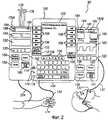
Фиг.2 - вид спереди на систему контроля за пациентом, выполненную в соответствии с другим предпочтительным воплощением настоящего изобретения, показывающий блок контролирования обезболивающих средств для пациента, блок контролирования двуокиси углерода и центральный интерфейсный блок, связывающий насосный блок с большой дозировкой и блок контролирования двуокиси углерода;FIG. 2 is a front view of a patient monitoring system in accordance with another preferred embodiment of the present invention, showing a painkiller monitoring unit for a patient, a carbon dioxide monitoring unit and a central interface unit connecting a high dosage pump unit and a carbon dioxide monitoring unit ;
Фиг.3 - вид сзади на центральный интерфейсный блок системы контроля за пациентом, показанный на чертежах фиг.1 и 2;Figure 3 is a rear view of the Central interface unit of the patient monitoring system shown in the drawings of Figures 1 and 2;
Фиг.4 - блок-схема центрального интерфейсного блока системы контроля за пациентом, изображенного на чертеже фиг.2;FIG. 4 is a block diagram of a central interface unit of a patient monitoring system shown in FIG. 2;
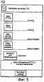
Фиг.5 изображает информационный дисплей центрального интерфейсного блока, изображенного на чертеже фиг.4, во время настройки блока контролирования двуокиси углерода, показывающий участки для введения величин;FIG. 5 is an information display of a central interface unit shown in FIG. 4 during setup of a carbon dioxide monitoring unit, showing portions for inputting values;
Фиг.6 изображает другой информационный дисплей центрального интерфейсного блока, изображенного на чертеже фиг.4, во время настройки блока контролирования двуокиси углерода с введенными величинами;Fig.6 depicts another information display of the Central interface unit shown in the drawing of Fig.4, during the setup of the carbon dioxide monitoring unit with the entered values;
Фиг.7 изображает другой информационный дисплей центрального интерфейсного блока, изображенного на чертеже фиг.4, во время настройки блока контролируемой подачи обезболивающего средства пациенту, показывающий выбор блоков;Fig.7 depicts another information display of the Central interface unit, shown in the drawing of Fig.4, during the setup of the block controlled delivery of painkillers to the patient, showing the choice of blocks;
Фиг.8 изображает другой информационный дисплей центрального блока интерфейса фиг.4 во время настройки блока контролируемой подачи обезболивающего средства пациенту, показывающий выполненные выборы блоков;Fig. 8 depicts another information display of the central block of the interface of Fig. 4 during the setting of the block for the controlled supply of pain medication to the patient, showing the choices made;
Фиг.9 изображает другой информационный дисплей центрального модуля интерфейса фиг.4 во время настройки блока контролируемой подачи обезболивающего средства пациенту, показывающий введенные величины;Fig.9 depicts another information display of the Central module of the interface of Fig.4 during the setup of the block controlled delivery of painkillers to the patient, showing the entered values;
Фиг.10 изображает информационный дисплей центрального интерфейсного блока, изображенного на чертеже фиг.4, после завершения настройки и во время работы;Figure 10 depicts the information display of the Central interface unit shown in the drawing of figure 4, after completing the settings and during operation;
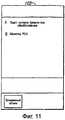
Фиг.11 изображает информационный дисплей центрального интерфейсного блока, показанного на чертеже фиг.4 с системой контроля за пациентом, находящейся в режиме подачи сигналов тревоги;11 depicts an information display of a central interface unit shown in FIG. 4 with a patient monitoring system in alarm mode;
Фиг.12 - вид спереди на систему контроля за пациентом, выполненную согласно другому ее воплощению в соответствии с аспектами настоящего изобретения, имеющую насосный блок контролируемой подачи обезболивающего средства пациенту, блок контролирования двуокиси углерода и мониторный блок импульсного оксигемометра;12 is a front view of a patient monitoring system made in accordance with another embodiment of the present invention, having a pump unit for controlled delivery of anesthetic to a patient, a carbon dioxide monitoring unit, and a pulse oximeter monitor unit;
Фиг.13 - вид спереди на систему контроля за пациентом при другом воплощении в соответствии с аспектами настоящего изобретения, имеющую насосный блок подачи обезболивающего средства пациенту и комбинированный мониторный блок контролирования двуокиси углерода/импульсного оксигемометра, оба из которых установлены в центральном интерфейсном блоке;13 is a front view of a patient monitoring system in another embodiment in accordance with aspects of the present invention, having an anesthetics pumping unit for a patient and a combined carbon dioxide / pulse oximeter monitor monitoring unit, both of which are installed in a central interface unit;
Фиг.14 изображает информационный дисплей центрального интерфейсного блока, изображенного на чертеже фиг.13, во время настройки блока контролирования двуокиси углерода/импульсного оксигемометра, показывающий поля значений величин;Fig.14 depicts the information display of the Central interface unit shown in Fig.13, during the setup of the carbon dioxide monitoring unit / pulse oximeter, showing the field values;
Фиг.15 изображает другой информационный дисплей центрального интерфейсного блока, изображенного на чертеже фиг.13, во время настройки блока контролирования двуокиси углерода/импульсного оксигемометра, показывающий введенные величины в полях их значений для установления диапазонов приемлемых величин физиологических параметров; иFig. 15 depicts another information display of the central interface unit shown in Fig. 13 during setup of the carbon dioxide monitoring unit / pulse oximeter, showing the entered values in the fields of their values to establish ranges of acceptable values of physiological parameters; and
Фиг.16 - блок-схема инфузионного насоса, выполненная в соответствии с аспектами настоящего изобретения, включающая интегрированные монитор двуокиси углерода и импульсный оксигемометр.FIG. 16 is a block diagram of an infusion pump in accordance with aspects of the present invention, including an integrated carbon dioxide monitor and a pulse oximeter.
ПОДРОБНОЕ ОПИСАНИЕ ПРЕДПОЧТИТЕЛЬНЫХ ВОПЛОЩЕНИЙ ИЗОБРЕТЕНИЯDETAILED DESCRIPTION OF THE PREFERRED EMBODIMENTS OF THE INVENTION
Следующие предпочтительные воплощения настоящего изобретения описаны в контексте программируемых модульных систем контроля за пациентом, раскрытых в патенте США №5713856, заявка на изобретение по которому под названием "Модульная система контроля за пациентом" подана 13 марта 1995 года, и в патенте США №5957885, заявка на изобретение по которому под названием «Система контролируемой подачи обезболивающего средства пациенту, контролируемая оксиметрией» подана 6 ноября 1996 года.The following preferred embodiments of the present invention are described in the context of programmable modular patient monitoring systems disclosed in US Pat. No. 5,713,856, the patent application of which is entitled "Modular Patient Monitoring System" filed March 13, 1995, and in US Pat. No. 5,957,885, application for an invention under which under the name "System for the controlled supply of painkillers to a patient controlled by oximetry" was filed November 6, 1996.
Оба эти патента принадлежат заявителю изобретения по настоящей заявке и включены здесь в их полном объеме посредством ссылки на них. Однако квалифицированный специалист в данной области признает, что раскрытые способы и устройство с готовностью могут быть приспособлены к более широкому применению, включая, но не ограничиваясь, другие системы контроля за пациентом и насосные инфузионные системы для вливаний лекарственных средств. Более того, как это будет также оценено квалифицированными специалистами в данной области, система доставки лекарственных средств с контролированием двуокиси углерода, выполненная в соответствии с настоящим изобретением, также может быть предусмотрена как автономный составной интегральный блок, как это далее более подробно рассматривается в совокупности с чертежом, изображенном на фиг.16.Both of these patents belong to the applicant of the invention in this application and are incorporated herein in their entirety by reference to them. However, a qualified specialist in this field recognizes that the disclosed methods and device can readily be adapted for wider use, including, but not limited to, other patient monitoring systems and pump infusion systems for drug infusions. Moreover, as this will also be appreciated by those skilled in the art, a carbon dioxide-controlled drug delivery system made in accordance with the present invention can also be provided as a stand-alone composite integral unit, as will be further described in more detail in conjunction with the drawing. shown in Fig.16.
Обращаясь теперь более детально к чертежам, на которых одинаковые цифровые обозначения для ссылки на них среди нескольких видов чертежей указывают на одни и те же или соответствующие элементы, можно видеть, что на чертеже, изображенном на фиг.1, показан вид спереди на модульную программируемую систему 90 контроля за пациентом, выполненную согласно предпочтительному воплощению настоящего изобретения. Система 90 контроля за пациентом содержит центральный интерфейсный блок 100, насосный блок 150А, блок 150В, который контролирует выдыхаемый воздух пациента для того, чтобы определить концентрацию выбранного компонента, и такой блок 150В капнографического типа предназначен для измерения количества двуокиси углерода (также определяемый как «блок контролирования двуокиси углерода»), и пробоотборник 133 выдыхаемого воздуха. Хотя это и не показано, но оба блока, а именно насосный блок 150А и блок 150В контролирования двуокиси углерода, связаны с пациентом. Хотя на чертеже фиг.1 показаны только два функциональных модуля, то есть насосный блок 150А и блок 150В контролирования двуокиси углерода, присоединенные к центральному интерфейсному блоку 100, система 90 контроля за пациентом может дополнительно включать другие функциональные модули, в зависимости от специфических потребностей пациента. Например, один или большее количество дополнительных функциональных блоков может быть связано или с насосным блоком 150А, или с капнографическим блоком 150В, включая, но не ограничиваясь насосами с большой дозировкой, регуляторами потока, шприцевыми насосами, насосами для контролируемой подачи обезболивающего средства пациенту, мониторами для контролирования двуокиси углерода, другими мониторами для анализа воздуха, мониторами импульсной оксиметрии, электрокардиографами, травматичными и нетравматичными приборами для наблюдения за кровяным давлением, мониторами слухового вызываемого потенциала для контролирования уровня сознания, мониторами мозговых кровяных потоков или мониторами мозгового насыщения кислородом и другими мониторами.Turning now in more detail to the drawings, in which the same numeric designations for reference among several types of drawings indicate the same or corresponding elements, it can be seen that in the drawing shown in Fig. 1, a front view of a modular programmable system is shown 90 patient monitoring performed in accordance with a preferred embodiment of the present invention. The
Центральный интерфейсный блок 100 вообще исполняет пять функций в системе 90 контроля за пациентом:The
(1) обеспечивает физическое присоединение системы 90 контроля за пациентом к таким структурам, как те, которые имеют стойки IV и которые являются спинками кроватей;(1) allows the physical connection of the
(2) обеспечивает электропитание системы 90 контроля за пациентом;(2) provides power to the
(3) обеспечивает наличие интерфейса между системой 90 контроля за пациентом и внешними устройствами;(3) provides an interface between the
(4) за исключением конкретной определенной информации обеспечивает наличие интерфейса пользователя с системой 90 контроля за пациентом;(4) with the exception of specific, specific information, provides a user interface with a
(5) контролирует и управляет всей работой системы 90 контроля за пациентом, включая интегрирование сигналов от мониторных блоков и/или от насосных блоков, для того, чтобы подавать сигналы тревоги и/или влиять на работу одного или большего количества насосных блоков.(5) monitors and controls the entire operation of the
Центральный интерфейсный блок 100 содержит информационный дисплей 102, который может использоваться во время настройки и во время выполнения рабочих процедур для того, чтобы облегчить ввод данных и редактирование. Информационный дисплей 102 может также отображать различные рабочие параметры во время работы, такого типа как название лекарственного средства, доза, скорость введения лекарственного средства, информация протокола вливания, интервал блокировки при контролируемых применениях обезболивающих средств у пациентов, конечные приливно-отливные концентрации двуокиси углерода и пределы частоты пульса для капнографического блока 150В. Если подключены другие функциональные блоки, такие как импульсный оксигемометр, информационный дисплей 102 может отображать насыщение кислородом, пределы частоты пульса и/или другую функциональную конкретную блочную информацию. Информационный дисплей 102 также используется для того, чтобы отобразить команды, подсказки, консультации и сигнальные условия, предоставляемые пользователю.The
Центральный интерфейсный блок 100 также содержит множество непрограммируемых клавиш 104 для ввода числовых данных и, наряду с функциональными клавишами 106, для ввода эксплуатационных команд. Кроме того, центральный интерфейсный блок 100 далее содержит непрограммируемую клавишу 108 переключателя POWER ON (ПИТАНИЕ ВКЛЮЧЕНО) для подключения к или отключения электрического питания от центрального интерфейсного блока 100, непрограммируемую клавишу 110 PAUSE (ПАУЗА) для временного исключения звуковых функциональных возможностей центрального интерфейсного блока 100 и непрограммируемую клавишу 112 OPTIONS (ВОЗМОЖНОСТИ ВЫБОРА) для обеспечения доступа пользователя к системе или к возможностям выбора функциональных блоков. Центральный интерфейсный блок 100 может далее содержать внешний компьютерный индикатор 114 для указания на то, что система 90 контроля за пациентом сообщается с совместимой внешней компьютерной системой, внешний индикатор 116 электропитания, предназначенный для того, чтобы указывать на то, что центральный интерфейсный блок 100 подсоединен к и работает от внешнего источника энергии, и внутренний индикатор 118 электропитания, предназначенный для того, чтобы указывать, что центральный интерфейсный блок 100 работает с использованием внутреннего источника энергии. Центральный интерфейсный блок 100 может также выполнять функцию контролирования устойчивостью против вибрации (на чертежах не показана), которая может блокировать работу предопределенного набора средств управления.The
Насосный блок 150А и капнографический блок 150В каждый включает в себя индикатор 155 положения канала, который освещает один из символов "А", "В", "С" или "D" для того, чтобы идентифицировать состояние канала этого функционального блока относительно системы 90 контроля за пациентом. Например, система 90 контроля за пациентом содержит два канальных положения А и В, причем положение А относится непосредственно к левому центральному интерфейсному блоку 100 (такому как насосный блок 150А, показанный на фиг.1), а положение В - к правому центральному интерфейсному блоку 100 (такому как капнографический блок 150В, изображенный на чертеже фиг.1). Поскольку как насосный блок 150А в канале А, так и капнографический блок 150В в канале В присоединены так, как показано на чертеже фиг.1, информационный дисплей 102 в интерфейсном блоке 100 указывает на положения А и В (примечание: при этом варианте воплощения изобретения насосный блок 150А обозначен на информационном дисплее 102 как "LVP/Continuous" (НАСОС С БОЛЬШОЙ ДОЗИРОВКОЙ/НЕПРЕРЫВНЫЙ РЕЖИМ), а капнографический блок 150В обозначен на информационном дисплее 102 как "CO2 MONITOR" (МОНИТОР ДЛЯ КОНТРОЛИРОВАНИЯ ДВУОКИСИ УГЛЕРОДА). Когда желательный функциональный блок выбран посредством нажатия на клавишу 156 CHANNEL SELECT (ВЫБОР КАНАЛА) для соответствующего функционального блока, информационный дисплей 102 конфигурируется таким образом, чтобы действовать как интерфейс пользователя для выбранного функционального блока. Конкретно информационный дисплей 102 конфигурируется в соответствии с функциональной конкретной областью для того, чтобы обеспечивать наличие функциональных конкретных дисплеев и программируемых клавиш, как это станет ясным из описания примера, приведенного ниже.The
Каждый функциональный блок имеет клавишу 156 CHANNEL SELECT (ВЫБОР КАНАЛА) для выбора функционального блока, клавишу 158 (1) PAUSE (ПАУЗА) для приостановки вливания в том случае, если функциональный блок является насосом и если происходит инфузия, или клавишу 158 (2) для приостановки контролируемой функции, если функциональный блок является контролирующим блоком, клавишу 160 RESTART (ПОВТОРНЫЙ ПУСК) для возобновления предварительно приостановленного вливания или контролируемой функции, и клавишу 162 CHANNEL OFF (КАНАЛ ВЫКЛЮЧЕН) для исключения выбора канала, и, если функциональный блок на канале был единственным работающим функциональным блоком, для выключения системы контроля 90 за пациентом. Кроме того, насосный блок 150А и капнографический блок 150В каждый содержит индикатор 164 для сигнального указания состояния и индикатор 166 STANDBY (РЕЗЕРВ) для того, чтобы указывать на резервное состояние. Насосный модуль 150А дополнительно содержит индикатор 168 INFUSING (ВЛИВАНИЕ) для того, чтобы указывать на условие вливания. Каждый индикатор иллюстративно подсвечивается, когда соответствующий функциональный блок находится в соответствующем состоянии.Each function block has a 156 CHANNEL SELECT key to select a function block, 158 (1) PAUSE key to pause the infusion if the function block is a pump and if infusion occurs, or 158 (2) key for suspend the monitored function, if the function block is the monitoring unit,
Насосный блок 150А содержит дисплей 152 канальных сообщений, который может использоваться для того, чтобы отобразить послания информационного, консультационного, сигнального характера или сообщения о сбоях системы, и дисплей 154 скорости, который может использоваться для того, чтобы отображать, например, скорость введения лекарственного средства, при которой работает насосный блок. Насосный блок 150А может также включать дверной замок (на чертежах не показан) для обеспечения сохранности хранимых наркотиков или других лечебных средств, которые подлежат вливаниям. Как известно из предшествующего уровня техники, насосный блок 150А может быть или блоком для контролируемого введения обезболивающих средств пациентам, или насосной системой, основанной на шприцевых насосах, или насосом с большой дозировкой, или насосом парентерального типа или являться другими соответствующими устройствами, которые легко могут определяться квалифицированным специалистом в данной области. Насосный блок 150А включает стандартные механизмы накачивания и обеспечения безопасности для того, чтобы управлять различными функциями, выполняемыми насосным устройством и такого типа как контролирование доставки жидкости пациенту и контролирование тракта жидкости для устранения закупоривания и наличия воздуха в канале.The
Подключенный к капнографическому блоку 150В пробоотборник 133 выдыхаемого воздуха предпочтительно забирает выдыхаемый воздух от носа и горла пациента и избирательно подает кислород пациенту. Выдыхаемый воздух перемещается к капнографическому блоку 150В через линию 137, где анализируется в масштабе реального времени концентрация двуокиси углерода капнографическим блоком 150В при предпочтительном использовании инфракрасной спектроскопии. Однако другие способы анализа двуокиси углерода могут использоваться, как это рассмотрено выше и понятно для квалифицированных специалистов в данной области. Альтернативно, пробоотборник 133 может включать в себя датчик (на чертежах не показан) для непосредственно анализа выдыхаемого воздуха и посылки сигнала через подключение линии 137 или через систему радиосвязи (на чертежах не показана) к мониторному блоку 150В. Капнографический блок 150В включает в себя несколько дисплеев 180, 182 и 183 для отображения данных информации, представляемых пользователю. Например, конечную приливно-отливную концентрацию двуокиси углерода (здесь обозначаемую как "ЕТСО2") отображает дисплей 180 при числовом значении для концентрации двуокиси углерода после выдоха и перед вдохом, выраженном предпочтительно в единицах миллиметров ртутного столба или в процентах. Дисплей 182 частоты дыхания показывает значение темпа, отображающего текущую частоту дыхания пациента, например, так, как это определено частотным анализом формы волны для двуокиси углерода. Дисплей 183 формы волны показывает концентрацию двуокиси углерода в крови пациента через какое-то время. Данные, показанные на дисплее 183 для формы волны, предпочтительно могут быть выборочно расширены или сжаты для анализа волновых характеристик или для анализа тенденций. Данные, показанные на дисплеях 180, 182 и/или 183, могут быть сглажены, скорректированы, усреднены по времени при анализировании, или ими могут иначе манипулировать перед показом на дисплее для того, чтобы обеспечить оптимальное клиническое значение пользователю. Например, капнографический блок 150В может выполнять осреднение для сглаживания волновой формы для двуокиси углерода, и горизонтальная ось времени может быть прервана и/или откорректирована или для волнового анализа двуокиси углерода, или для анализа тенденций.The exhaled
Как будет рассмотрено более подробно ниже, данные, генерированные капнографическим блоком 150В, подаются на центральный интерфейсный блок 100 и могут использоваться для того, чтобы вызывать сигнал тревоги, сообщать о консультации на информационном дисплее 102, автоматически останавливать работу насосного блока 150А или иным образом корректировать или управлять подачей лекарственного средства или другой медицинской жидкости насосным блоком 150А. Например, интерфейсный блок 100 может быть запрограммирован таким образом, чтобы автоматически прекращать работу насосного блока 150А, если у пациента значения конечной приливно-отливной концентрации двуокиси углерода выходят за пределы предопределенного диапазона их допустимых значений. Альтернативно, насос 150А и монитор 150В могут быть связаны непосредственно друг с другом для того, чтобы влиять на подачу жидкости этому пациенту на основании контролируемых параметров. При другом воплощении капнографический монитор 150В или интерфейсный блок 100 включает алгоритм анализа формы волны для того, чтобы анализировать капнографическую форму волны и влиять на работу насоса 150А на основании некоторых характеристик формы волны, как это известно при существующем уровне техники. При другом воплощении настоящего изобретения, интерфейсный блок 100 включает в себя много-параметрический алгоритм для того, чтобы вычислить один или большее количество показателей состояния пациента, используя данные информации от множества различных применяемых физиологических мониторов, и использует расчетные показатели для того, чтобы влиять на контролирование работы насоса 150А.As will be discussed in more detail below, the data generated by the
На чертеже фиг.2 показано альтернативное воплощение системы 90 контроля за пациентом, при этом насосный блок 150А является скорее блоком для контролируемого вливания обезболивающих средств пациенту, чем насосом с большой дозировкой. Насосный модуль 150А, как показано, имеет по существу те же самые интерфейсные дисплеи и нажимные клавиши, как те, которые показаны на чертеже фиг.1; однако, насосный блок 150А, изображенный на чертеже фиг.2, также включает толкатель 175 шприца и шприц 176. Насосный блок-модуль 150А для контролируемого вливания обезболивающих средств пациенту далее включает в себя инфузионное насосное устройство, находящееся в пределах его корпуса, которое управляет толкателем 175 шприца для того, чтобы вливать болюсные дозы наркотических обезболивающих средств из шприца в пациента при реагировании в ответ на команды от центрального интерфейсного блока 100. Дисплей 154 показывает, например, скорость введения лекарственного средства, при которой работает насос 150А для контролируемого вливания обезболивающих средств пациенту, или интервал отключения от пациента. Интерфейсный блок 100, когда он конфигурирован с насосом для контролируемого вливания обезболивающих средств пациенту как насосный блок 150А, включает в себя кабель 134 запроса дозы для контролируемого вливания обезболивающих средств пациенту, связанный с карманной кнопкой 135 запроса дозы или с другим устройством приведения в действие.2, an alternative embodiment of a
Обращая теперь внимание на чертеж, показанный на фиг.3, можно видеть, что в задней части центрального интерфейсного блока 100 имеется, по крайней мере, один интерфейс 120 для внешней связи, по крайней мере, один порт 122 интерфейса и, по крайней мере, один порт 123 для контролируемого вливания обезболивающих средств пациенту. Интерфейс 120 для внешней связи и интерфейсный порт 122 могут использоваться для того, чтобы загружать и выгружать информацию и данные и могут также действовать как средство, контролирующее сеть "интерфейс-пациент" и как система вызова медсестры, или как интерфейс для внешнего оборудования такого типа, как устройство для считывания штрихового кода для того, чтобы обеспечить наличие средств ввода лекарственного средства и/или информацией для пациента из записей, касающихся лечения и данных о пациенте, получаемых от устройств информации и идентификации такого типа, как штриховые коды, расположенные на пациенте, медсестре или клиническом враче, на мешке с медицинской жидкостью и на других устройствах. Выполнение этих функций с помощью интерфейса 120 для внешней связи и интерфейсных портов 122 обеспечивает наличие больших функциональных возможностей и адаптируемости, сберегают материальные средства и уменьшают ошибки на входе. В частности, клинические ошибки, связанные с программированием насосного блока 150А, могут быть уменьшены таким образом, что благодаря этому уменьшаются риски угнетения дыхания, связанного с приемом снотворных, наркотических, обезболивающих, анестезирующих средств или других лекарств при использования насосного блока 150А.Turning now to the drawing shown in FIG. 3, it can be seen that at the rear of the
Порт 123 для контролируемого вливания обезболивающих средств пациенту обеспечивает связью между центральным интерфейсным блоком 100 и одним концом кабеля 134 запроса дозы при контролируемом вливании обезболивающих средств пациенту (см. чертеж на фиг.2), если насосный блок 150А является насосом для контролируемого вливания обезболивающих средств пациенту. На противоположный конце кабеля 134 запроса дозы для контролируемого вливания обезболивающих средств пациенту находится переносная кнопка запроса дозы при контролируемом вливании обезболивающих средств пациенту или другое устройство 135 приведения в действие, которое срабатывает для того, чтобы запросить дозу обезболивающего средства для пациента при контролируемом его вливании. Следует понимать, что хотя центральный интерфейсный блок содержит порт 123 для контролируемого вливания обезболивающих средств пациенту при предпочтительном воплощении, насосный блок 150А может также содержать порт для контролируемого вливания обезболивающих средств пациенту (не показанный на чертеже), который обеспечивал бы подобное подключение от насосного блока 150А через кабель 134 запроса дозы при контролируемом вливании обезболивающих средств пациенту на устройство 135 приведения в действие запроса дозы.
Обращая теперь внимание на чертеж фиг.4, который изображает блок-схему центрального интерфейсного блока 100, выполненного в соответствии с аспектами настоящего изобретения, можно видеть, что микропроцессорный регулятор 264 получает и обрабатывает данные информации и команды от пользователя и связывается с функциональными блоками и другими внешними устройствами. Микропроцессорный регулятор 264 непосредственно управляет работой регулятора 274 внешней связи, который контролирует порт 123 для контролируемого вливания обезболивающих средств пациенту и поток данных информации через интерфейсные порты 122 и/или интерфейс 120 для внешней связи. Микропроцессорный регулятор 264 также контролирует работу регулятора 272 для внутренней связи, который управляет внутренними коммуникационными портами 280 и 281. Внутренние коммуникационные порты 280 и 281 включены в каждый функциональный блок так же, как и в центральный интерфейсный блок 100, и обеспечивают наличие интерфейсов данных информации и команд между центральным интерфейсным блоком 100 и применяемыми функциональными блоками 150А, 150В.Turning now to the drawing of FIG. 4, which depicts a block diagram of a
Во время работы системы контроля 90 за пациентом, в которой насосный блок 150А является насосом для контролируемого вливания обезболивающих средств пациенту, как показано на чертеже фиг.2, когда срабатывает устройство 135 приведения в действие запроса дозы, микропроцессор 264 получает сигнал запроса дозы через кабель 134 запроса дозы и порт 123 для контролируемого вливания обезболивающих средств пациенту. Если микропроцессор 264 решает, что не имеется никаких ограничений в приеме требуемой болюсной дозы наркотических обезболивающих средств, тогда микропроцессор 264 может посылать сигнал насосному блоку 150А через регулятор 272 для внешней связи и внутренний коммуникационный порт 280 и/или порт 281, инструктируя насосный блок 150А в отношении приема требуемой болюсной дозы.During operation of the
Микропроцессорный регулятор 264 также обеспечивает координацию действий между функциональными блоками, такими как насосный блок 150А и капнографический блок 150В. Например, клинический врач может настраивать систему 90 контроля за пациентом с насосным блоком 150А для того, чтобы обеспечить контролируемый прием обезболивающих средств пациентами, и с капнографическим блоком 150В для того, чтобы контролировать конечную приливно-отливную концентрацию двуокиси углерода и частоту дыхания при контролируемом приеме обезболивающего средства пациентом. Произвольно один или большее количество дополнительных мониторов, таких как блок 150С импульсной оксиметрии, как показано на чертеже фиг.12, может быть последовательно подключено к системе 90 контроля за пациентом и настроено для того, чтобы контролировать насыщение кислородом крови и частоту пульса, например, так, как описано более подробно ниже. Клинический врач может определить минимальное и/или предельное значение конечной приливно-отливной концентрации двуокиси углерода, частоты дыхания и/или других контролируемых параметров, благодаря чему эффективно устанавливается диапазон допустимых значений для этих параметров. Если насыщение кислородом крови пациента или частота пульса находится вне отобранного приемлемого диапазона так, как в случае, когда этот параметр становится меньше, чем минимальный его уровень, или больше, чем его максимальный уровень, установленный клиническим врачом, монитор 150В для конечной приливно-отливной концентрации двуокиси углерода может посылать пусковой сигнал микропроцессорному регулятору 264 через регулятор 272 для внутренний связи и внутренний коммуникационный порт 280 и/или порт 281. При ответе реагированием микропроцессорный регулятор 264 может активизировать звуковой сигнал тревоги 276 и подать его на громкоговоритель 278, например послать оптический сигнал тревоги информационному дисплею 102 (см. чертежи на фиг.1 и 2), приостановить работу насосного блока 150А, откорректировать скорость потока через насосный блок 150А и/или выполнить другую предопределенную функцию. Например, в ответ на выход замера из диапазона изменения конечных приливно-отливных концентраций двуокиси углерода при контролируемом приеме обезболивающего средства пациентом микропроцессорный регулятор 264 может прекращать весь дальнейший прием обезболивающих средств до тех пор, пока чрезвычайно низко или высоко конечное приливно-отливное значение концентрации двуокиси углерода и/или до тех пор, пока не будет решена проблема с местоположением величины частоты дыхания таким способом как вмешательство клинического врача. Альтернативно микропроцессорный регулятор 264 может просто блокировать устройство 135 приведения в действие для контролируемого приема пациентом обезболивающего средства так, что пациент не сможет осуществлять дальнейший автономный прием самостоятельно. Таким образом, после того, как соответствующие значения будут настроены, центральный интерфейсный блок 100 будет обеспечивать связь и координацию между насосным блоком 150А и капнографическим блоком 150В для того, чтобы гарантировать повышенную безопасность и уменьшенный риск поражений, вызванных угнетением дыхания.
При альтернативном воплощении микропроцессорный регулятор 264 сможет скорее включить программные инструкции для контролирования изменений в концентрации двуокиси углерода или других данных информации, вырабатываемых капнографическим блоком 150В, и принимать решения о том, вмешиваться ли пациенту в работу насосного блока 150А на основе изменений в контролируемых данных информации, чем микропроцессорный регулятор 264 приостановит работу насосного блока 150А в ответ только на выход за диапазон сигнала от капнографического блока 150В или от другого функционального блока.In an alternative embodiment, the
Взаимодействия и функции центрального интерфейсного блока 100, насосного блока 150А и капнографического блока 150В будут теперь описаны в совокупности с чертежами на фиг.5-11, которые показывают некоторые из поэтапных положений информационного дисплея во время настройки и работы системы 90 контроля за пациентом. В то время как следующий пример описывает настройку работы системы при контролируемом приеме пациентом обезболивающего средства при использовании одиночного насоса 150А для контролируемого приема пациентом обезболивающего средства и одиночного капнографического монитора 150В, квалифицированный специалист в данной области придет к заключению о том, что настоящее изобретение охватывает запрограммированные протоколы вливания, использующие другие типы насосов для вливаний и мониторов и другие их количества.The interactions and functions of the
Чтобы реализовать предпочтительное воплощение системы 90 контроля за пациентом, клинический врач сначала подключает пробоотборник 133 выдыхаемого воздуха к пациенту так, как это показано на чертежах фиг.1 и 2. Клинический врач тогда выбирает капнографический блок 150В и его соответствующий канал, нажимая на клавишу 156 SELECT (ВЫБИРАТЬ) на капнографическом блоке 150В. Выбирая капнографический блок 150В, конфигурируют информационный дисплей 102 таким образом, чтобы он действовал как интерфейс пользователя, и таким образом обеспечивается наличие конкретных дисплеев и программируемых клавиш капнографических функций так, как показано на чертеже фиг.5. Клинический врач может или вводить минимальные и предельные значения, нажимая на соответствующую функциональную клавишу и вводя связанные предельные числа, или восстанавливать предыдущие значения для конечной приливно-отливной концентрации двуокиси углерода и частоты дыхания, нажимая на функциональную клавишу ниже метки RESTORE (ВОССТАНОВИТЬ).To implement the preferred embodiment of the
На чертеже фиг.6 показан информационный дисплей 102 после того, как клинический врач ввел или восстановил предыдущие значения. До начала капнографического контролирования посредством нажатия на функциональную клавишу, связанную с меткой START (ПУСК), клинический врач может выбирать автоматическое выключение одного или большего количества других функциональных блоков, таких как блок 150А для контролируемого вливания обезболивающего средства в пациента таким образом, что центральный интерфейсный блок 100 будет отключать отобранный(ые) функциональный(ые) блок(и), если конечная приливно-отливная концентрация двуокиси углерода в пациенте, или частота дыхания, или некоторая их комбинация выходит за пределы указанных максимальных и минимальных уровней. Альтернативно информационный дисплей 102 может включать параметры или протоколы для капнографического анализа формы волны у пациента и для настройки пределов при выявленных показателях. Как только начинается капнографическое контролирование, конечная приливно-отливная концентрация двуокиси углерода в пациенте, частота дыхания и капнографическая форма волны отображаются на дисплеях 180, 181 и 182 блока 150В для двуокиси углерода, как это предварительно описано и показано в чертежах на фиг.1 и 2. Хотя при предпочтительном воплощении системы 90 контроля за пациентом автоматически начинают подаваться как звуковой 276/278, так и оптический через дисплей 102 сигналы тревоги, такие как включение сигнала 282 вызова медсестры, если конечная приливно-отливная концентрация двуокиси углерода в пациенте или частота дыхания падает ниже или увеличивается выше конкретных минимального или максимального уровней, система 90 контроля за пациентом может быть конфигурирована таким образом, что клинический врач в таком случае сможет также выбирать конкретные сигналы тревоги и уведомления медицинскому персоналу.6, an
При предпочтительном воплощении настоящего изобретения, предельные величины конечной приливно-отливной концентрации двуокиси углерода в пациенте, частота дыхания и другие параметры хранятся в базе данных памяти 250 в интерфейсном блоке 100 (см. чертеж на фиг.4) или в мониторе 150В системы контроля за пациентом. Таким образом, скорее пользователь может повторно вызывать предварительно запрограммированные значения и/или конфигурационные протоколы из базы сохраняемых данных для того, чтобы экономить время и сводить к минимуму ошибки программирования, чем вводить вручную величины, используя числовые клавиши клавиатуры 104 (см. чертеж на фиг.2).In a preferred embodiment of the present invention, the ultimate tidal carbon dioxide concentration limit in a patient, respiratory rate, and other parameters are stored in a
Сохранение базы данных информации об установленных стандартах для параметров вливания лекарственного средства и пределов физиологических параметров, таких как максимальные и минимальные концентрации двуокиси углерода и максимальные и минимальные значения частоты дыхания, также помогает в стандартизации качества ухода за пациентами в клиническом учреждении. При некоторых воплощениях значения параметра вливания или пределы физиологических параметров могут быть введены автоматически по машинночитаемой метке, например, при использовании устройства для считывания штрихового кода (на чертежах не показано) с меткой штрихового кода, установленной на мешке, или на шприце, или на другом контейнере с лекарственной жидкостью, в котором хранится эта жидкость, подлежащая вливанию. Такие значения параметра вливания и значения физиологических параметров могут также быть введены другими средствами, такими как подключение к внешнему процессору, такому как госпитальный сервер, подключение к портативному электронному секретарю с данными информации и к другим устройствам. Подключения к этим устройствам могут осуществляться способами и такими как постоянное соединение, связь с помощью инфракрасного излучения, радиочастотная связь, использование идентификационной интегральной схемы с инфракрасным излучением, связь с «синим зубцом» или другие средства связи.Maintaining a database of information on established standards for drug infusion parameters and physiological parameter limits, such as maximum and minimum carbon dioxide concentrations and maximum and minimum respiration rates, also helps to standardize the quality of patient care in a clinical setting. In some embodiments, infusion parameter values or physiological parameter limits can be entered automatically using a machine-readable label, for example, using a barcode reader (not shown in the drawings) with a barcode label mounted on a bag, or on a syringe, or on another container with the medicinal fluid in which this fluid to be infused is stored. Such infusion parameter values and physiological parameter values can also be entered by other means, such as connecting to an external processor, such as a hospital server, connecting to a portable electronic secretary with information data and to other devices. Connections to these devices can be carried out by methods and such as permanent connection, communication using infrared radiation, radio frequency communication, the use of an identification integrated circuit with infrared radiation, communication with a "blue tooth" or other means of communication.
Клинический врач тогда выбирает блок 150А для контролируемого вливания обезболивающих средств в пациента и его соответствующий канал, нажимая на клавишу 156 SELECT (ВЫБИРАТЬ) на насосном блоке 150 А для контролируемого вливания обезболивающих средств в пациента (см. чертеж на фиг.1). Посредством выбора насосного блока 150А для контролируемого вливания обезболивающих средств в пациента информационный дисплей 102 конфигурируется таким образом, чтобы действовать как интерфейс пользователя, и таким образом обеспечивает наличие функционально-специализированных дисплеев и программируемых клавиш, как показано на чертежах фиг.7-9. В этом примере дисплеи предназначены для конкретных насосов, используемых для контролируемого вливания обезболивающих средств в пациента. Клинический врач может сначала восстанавливать предыдущие блоки дозирования и болеутоляющую концентрацию или выбирать единицы дозирования, например, в виде микрограмма, миллиграмма или миллилитра и вводить болеутоляющую концентрацию так, как показано на чертежах фиг.7 и 8. Затем, как показано на фиг.9, клинический врач может вводить или восстанавливать предыдущие параметры для болюсной дозировки. Для соблюдения дополнительной предосторожности и для того, чтобы предотвратить дальнейшее угнетение дыхания и депрессию центральной нервной системы, при альтернативном воплощении настоящего изобретения система 90 контроля за пациентом или насосный блок 150А может потребовать от клинического врача введения предельных дозировок и таких как максимальная доза в час или в течение 24-часового периода времени.The clinician then selects the 150A unit for the controlled infusion of painkillers into the patient and its corresponding channel by pressing the 156 SELECT key on the 150 A pump unit for the controlled infusion of painkillers into the patient (see drawing in FIG. 1). By selecting a
После ввода параметров болюсной дозировки и/или других параметров вливания лекарственного средства клинический врач может пожелать управлять фоновым непрерывным вливанием наркотических обезболивающих средств, нажимая на функциональную клавишу 106, смежную метке 252 CONTINUOUS (НЕПРЕРЫВНЫЙ РЕЖИМ). Использование фонового вливания в сочетании с требуемыми пациентом дозами обеспечивает уровень наркотического обезболивания, достаточный в течение периода времени его низкой активности, когда пациент спит. Таким образом, когда пациент пробуждается и требует дополнительного обезболивания из-за увеличенных уровней активности, пациент может собственноручно контролировать дополнительный прием обезболивающих средств для удовлетворения этих потребностей в обезболивании. Если выбирается фоновое непрерывное вливание посредством нажатия на функциональную клавишу 106, смежную метке 252 CONTINUOUS (НЕПРЕРЫВНЫЙ РЕЖИМ), информационный дисплей 102 позволяет клиническому врачу вводить желательную непрерывную дозу вливания. На чертеже фиг.9 показан информационный дисплей 102 после введения клиническим врачом значений как для болюсного дозирования вливания пациенту, так и для непрерывного дозирования.After entering bolus dosage parameters and / or other drug infusion parameters, the clinician may wish to control the continuous background infusion of narcotic painkillers by pressing the
Для параметров вливания, таких как параметры инфузии при контролируемом вливании обезболивающего средства в пациента, показанные на чертеже фиг.9 (КАПЛЯ ДЛЯ ПАЦИЕНТА, ИНТЕРВАЛ БЛОКИРОВКИ, МАКСИМАЛЬНАЯ ДОЗА В ЧАС, НЕПРЕРЫВНЫЙ РЕЖИМ и КОНЦЕНТРАЦИЯ), хранимая библиотека лекарственных средств может находиться в насосе или в системе контроля за пациентом, и в библиотеке хранятся предварительно установленные величины. Эти предварительно установленные величины могут содержать значения «постоянных» и «запрограммированных» пределов для параметров дозирования и других параметров инфузии. Пределы могут быть установлены клиникой или учреждением, в пределах которого система 90 контроля за пациентом постоянно находится. Как только значения вводятся в систему 90 контроля за пациентом клиническим врачом, как показано на чертеже фиг.9, микропроцессорный регулятор 264, согласно его программированию, вводит этап проверки, при которой он сравнивает каждое из этих отобранных значений по отношению к хранимым величинам в библиотеке для того, чтобы проверить, что отобранные значения находятся в пределах приемлемых диапазонов. Если выбранное значение нарушает постоянный предел, микропроцессорный регулятор 264 может подать сигнал тревоги и потребовать изменения значения прежде, чем начнется работа системы 90 контроля за пациентом. Если выбранное значение нарушает программируемый предел, микропроцессорный регулятор 264 может потребовать подтверждения от клинического врача о том, что он или она понимает, что введенное значение находится за программируемым пределом и что эта величина, однако, должна остаться в силе. Хотя в предпочтительном воплощении библиотека лекарственных средств хранится в системе контроля за пациентом, библиотека или библиотеки могут быть расположены в другом месте. Например, в том случае, когда системы контроля за пациентом 90 связаны со стационарным или с другим сервером, такая библиотека лекарственных средств может быть расположена в отдаленном сервере, и система 90 контроля за пациентом может связываться с библиотекой лекарственных средств, хранимой в отдаленном сервере в течение времени проверки для того, чтобы получать приемлемые диапазоны. При другом примере библиотека лекарственных средств может быть расположена в переносном электронном секретаре с данными информации (здесь он обозначен как "PDA"), таком как тот, который имеет торговую марку Palm Pilot™, или в переносном компьютере, таком как портативная ЭВМ, или прикроватный компьютер пациента, или стационарный компьютер медсестры, или другой компьютер.For infusion parameters, such as infusion parameters for a controlled infusion of anesthetic into the patient, shown in the drawing of Fig. 9 (DROP FOR A PATIENT, INTERVAL BLOCK, MAXIMUM DOSE PER HOUR, CONTINUOUS MODE, and CONCENTRATION), the stored drug library may be in the pump or In the patient monitoring system, and in the library, preset values are stored. These pre-set values may contain values of “constant” and “programmed” limits for dosing parameters and other infusion parameters. The limits can be set by the clinic or institution within which the
Связь между системой 90 контроля за пациентом и удаленной библиотекой лекарственных средств может быть осуществлена с помощью средств связи с инфракрасным излучением, средств радиочастотной связи, средств связи типа «синий зубец» РФ или посредством других средств. Клинический врач может перевозить переносной электронный секретарь с данными информации, имеющий библиотеку лекарственных средств, и прежде, чем система 90 контроля за пациентом начнет свою работу, должна поддерживаться связь с переносным электронным секретарем, имеющим данные информации, для того, чтобы сравнивать введенные величины с постоянными и программируемыми пределами их значений. Возможны другие устройства для хранения библиотек.The connection between the
Как только завершаются вышеупомянутые этапы, клинический врач присоединяет приспособление 254 для контролируемого приема пациентом обезболивающего средства (см. чертеж на фиг.2) к устройству (на чертеже не показано) для постоянного доступа в кровеносный сосуд пациента и нажимает на программируемую клавишу 106, смежную метке 256 START (ПУСК), на центральном интерфейсном блоке 100. Насосный блок 150А теперь работает с непрерывным контролированием концентрации двуокиси углерода в выдыхаемом воздухе и частоты дыхания со стороны капнографического блока 150В. Насосный блок 150А для контролируемого вливания обезболивающего средства пациенту начинает непрерывную фоновую инфузию, если она была выбрана. Кроме того, пациент может теперь запрашивать дозу наркотических обезболивающих средств в любое время посредством устройства 135 осуществления запроса дозы. Вопрос о том, получит ли пациент фактически требуемую болеутоляющую дозу, зависит от пределов требуемого дозирования для пациента, если таковые вообще имеются, и такими пределами являются текущий конечный уровень приливно-отливной концентрации двуокиси углерода и частота дыхания, отнесенные к пределам, установленным клиническим врачом.As soon as the above steps are completed, the clinician attaches the
Обращая теперь внимание на чертеж, показанный на фиг.10, можно видеть, что положения А и В на информационном дисплее 102 уведомляют клинического врача о том, что два функциональных блока, размещенных в канальных положениях А и В, связаны с центральным интерфейсным блоком 100. Информационный дисплей 102 может далее использоваться для того, чтобы указывать на состояние каждого функционального блока, занимающего каждый соответствующий канал в системе 90 контроля за пациентом. Например, информационный дисплей 102 в канале А, соответствуя блоку 150А для контролируемого вливания обезболивающего средства пациенту и занимая канал А, может быть конфигурирован для того, чтобы указывать на болюсную дозировку и на фоновую непрерывную дозировку вливания. Кроме того, информационный дисплей 102 в канале 150В, соответствуя капнографическому блоку 150В (также называемому как «Монитор для контролирования двуокиси углерода») и располагаясь в пределах канала В, может быть конфигурирован для того, чтобы указывать на минимальный и максимальный уровни конечной приливно-отливной концентрации двуокиси углерода и частоты дыхания. Система 90 для контроля за пациентом может также конфигурироваться таким образом, что информационный дисплей 102 в канале В отображает текущий процентный уровень конечной приливно-отливной концентрации двуокиси углерода и частоту дыхания. Естественно, если применяются другие мониторы или насосы, соответствующая информация от тех блоков может также быть отображена на информационном дисплее 102.Turning now to the drawing shown in FIG. 10, it can be seen that positions A and B on the
В том случае, когда значение конечной приливно-отливной концентрации двуокиси углерода или частоты дыхания находится за максимальным и минимальным уровнями, установленными клиническим врачом, центральный интерфейсный блок 100 немедленно прекращает работу насосного блока 150А, предназначенного для контролируемого вливания обезболивающего средства в пациента, и таким образом он останавливает дальнейший прием лекарства при любом фоновом вливании и болюсный прием доз. Избирательно система 90 контроля за пациентом может быть запрограммирована таким образом, чтобы скорее корректировать, чем останавливать фоновое вливание при непрерывном темпе потока или болюсное дозирование при реагировании в ответ на капнографические данные или на данные информации, полученные от других присоединенных мониторов, если они имеются. Как проиллюстрировано на чертеже, изображенном на фиг.11, позиция А информационного дисплея 102 указывает на состояние ОТКЛЮЧЕНИЯ ВЛИВАНИЯ ОБЕЗБОЛИВАЮЩЕГО СРЕДСТВА ПРИ СИГНАЛЕ ТРЕВОГИ у насосного блока 150А при контролируемом вливании обезболивающего средства в пациента. Кроме того, центральный интерфейсный блок 100 активизирует подачу звукового сигнала 276 тревоги посредством громкоговорителя 278 или иным способом подает визуальный сигнал тревоги на информационном дисплее 102, осуществляет проблесковую сигнализацию индикатором 164 ALARM (ТРЕВОГА) на насосном блоке 150А при контролируемом вливании обезболивающего средства в пациента и/или на капнографическом блоке 150В и посылает аварийный сигнал через порты интерфейса 122 и через регулятор 274 для внешней связи для того, чтобы привести в готовность соответствующий медицинский персонал сигналом тревоги, таким как вызов медсестры. Таким образом, обеспечиваются более быстрое реагирование и вмешательство медицинским персоналом при угнетении дыхания пациента из-за приема наркотических обезболивающих средств.In the event that the value of the final tidal concentration of carbon dioxide or respiratory rate is beyond the maximum and minimum levels set by the clinician, the
Обращая теперь внимание на чертеж, показанный на фиг.12, можно видеть, что альтернативное воплощение системы 300 контроля за пациентом в соответствии с аспектами настоящего изобретения включает в себя интерфейсный блок 100, насосный блок 150А и капнографический блок 150В, как описано выше, и дополнительно оно предусматривает включение в эту систему блока 150С импульсной оксиметрии для обеспечения нетравмирующего измерения уровней насыщении кислородом крови и частоты пульса. Блок 150С импульсной оксиметрии содержит датчик 322 импульсной оксиметрии, например двойной датчик длины волны, который присоединяется к участку тела пациента, содержащему венозный поток и такому как палец 324 или мочка уха. Блок 150С импульсной оксиметрии получает сигналы от датчика 322 через соединительный кабель 326 и интерпретирует сигналы в соответствии со стандартной операцией импульсного оксигемометра, что должно быть понятным для квалифицированных специалистов данной области. Примеры датчиков импульсной оксиметрии раскрыты в патенте США №5437275, авторами изобретения по которому являются Амундсен и др., и в патенте США №5431159, авторами изобретения по которому являются Бейкер и др. По этим сигналам датчика блок 150С импульсной оксиметрии импульса может определять процент насыщения кислородом крови пациента, т.е. показатель в виде процента насыщения кислородом (SpO2), и частоту пульса. Блок 150С импульсной оксиметрии содержит дисплей 310 для показателя SpO2 % для отображения процента насыщения кислородом крови пациента и дисплей 320 для отображения частоты пульса пациента.Turning now to the drawing shown in FIG. 12, it can be seen that an alternative embodiment of a
Пользователь может программировать систему 300 контроля за пациентом, например, используя программные этапы, подобные тем, которые описаны со ссылками на чертежи, изображенные на фиг.5-10, для того, чтобы сообщать сигнал тревоги, отображать данные консультации, отключать насосный блок 150А или изменять его работу, если один или большее количество величин измерения конечной приливно-отливной концентрации двуокиси углерода, частоты дыхания, процента насыщения кислородом крови или частоты пульса или комбинация этих величин находятся вне предопределенного диапазона их допустимых значений. При одном воплощении настоящего изобретения измерения от одного или большего количества функциональных блоков 150В или 150С могут вызывать начало запрограммированной последовательности в интерфейсном блоке 100, который заканчивает конкретный протокол доставки жидкости и начинает осуществлять новый протокол доставки от насосного блока 150А или другого применяемого насосного блока (не показанного на чертежах).The user can program the
Что касается чертежа на фиг.13, то можно отметить, что на нем показано другое воплощение системы 400 контроля за пациентом, включающей аспекты настоящего изобретения, при котором она содержит интегрированный блок 450В капнографической/импульсной оксиметрии. Блок 450В капнографической/импульсной оксиметрии объединяет функции блока 150В для двуокиси углерода и блока 150С импульсной оксиметрии, как это описано выше, в один интегрированный функциональный блок 450В. Блок 450В капнографической/импульсной оксиметрии включает в себя дисплей 410 для показаний процента насыщения кислородом крови, дисплей 420 для показаний частоты пульса, дисплей 430 для показаний конечной приливно-отливной концентрации двуокиси углерода, дисплей 440 для показаний частоты дыхания и дисплей 442 для показаний формы волны для двуокиси углерода. Индикаторы 164, 166 и 155 и выключатели 156, 158, 160 и 162 являются такими, как те, которые описаны выше в отношении других воплощений изобретения. Интегрированный блок 450В капнографической/импульсной оксиметрии может быть запрограммирован пользователем, или альтернативно информацией программы, хранимой в памяти 250 (см. чертеж на фиг.4) интерфейсного блока 100 или непосредственно в блоке 450В капнографической/импульсной оксиметрии. На чертеже фиг.13 показаны насосный блок 150А для контролируемого вливания в пациента обезболивающего средства, подключенный к одной стороне интерфейсного блока 100, и блок 150В для контролирования двуокиси углерода/для импульсной оксиметрии (SpO2), подключенный к другой стороне интерфейсного блока 100. Соответственно, пациент имеет в его руке кнопку 135 запроса дозы контролируемого вливания в него обезболивающего средства, связанную с центральным интерфейсным блоком 100 через кабель 134 для управления болюсным дозированием обезболивающего средства, которое нужно для самостоятельного контролирования вливания от насосного блока 150А, предназначенного для контролируемой инфузии обезболивающего средства посредством приспособления 254 для дозирования жидкости. Пациент также контролируется по его уровню количества двуокиси углерода и по дыханию с помощью капнографического блока, образующего часть блока 150В. Пробоотборник 133 выдыхаемого воздуха устанавливается на участке носа и горла пациента и подает выдыхаемый воздух к капнографической части блока 150В через линию 137. Пациент также контролируется по уровню насыщения кислородом его крови с помощью импульсного оксигемометра, который образует часть блока 150В. Датчик 322 импульсной оксиметрии связан с пальцем пациента, и сигналы датчика сообщаются с частью блока 150В для импульсной оксиметрии посредством кабеля 326.As for the drawing in FIG. 13, it can be noted that it shows another embodiment of a
На чертежах фиг.14 и 15 изображены экраны для настроек, находящиеся на информационном дисплее 102, предназначенном для пользователя для того, чтобы вводить максимальные и минимальные значения для каждого из измеряемых параметров и для осуществления начала вливания.The drawings of Figs. 14 and 15 show screens for settings located on the
Обращая внимание на блок-схему, показанную на чертеже фиг.16, можно видеть, что при альтернативном воплощении системы 490 контроля за пациентом в соответствии с аспектами настоящего изобретения она включает в себя интегрированный программируемый насос 500 для вливаний с блоком 510 привода насоса, интерфейс пользователя для ввода 520 и отображения 530 информации, микропроцессорный регулятор 540, который управляет и контролирует работу интерфейса 520, 530 пользователя и блока 510 привода насоса, память 550, которая связана с микропроцессорным регулятором 540 для хранения команд программы для работы системы 490 контроля за пациентом и может также сохранять библиотеку или библиотеки наркотических средств, насосных параметров и физиологических параметров, пригодных для использования с мониторами. Инфузионный насос 500 вообще подобен насосу для вливаний, раскрытому в патенте США №5800387, выданном на имя Даффи и других заявителей, который включен в описание данного настоящего изобретения полностью посредством ссылки на него. Однако система 490 контроля за пациентом также включает капнографический блок 560 и блок 570 импульсного оксигемометра внутри корпуса 580 системы. Микропроцессорный регулятор 540, подобно центральному интерфейсному блоку 100 из вышеупомянутых описанных блочных систем 90, 300, и 400, контролирует значения, генерированные капнографическим блоком 560 и/или блоком 570 импульсного оксигемометра, и влияет на работу насоса 510 при реагировании в ответ на предопределенные изменения в измеренных величинах.Referring to the block diagram shown in FIG. 16, it can be seen that, in an alternative embodiment of the
Хотя различные воплощения изобретения были описаны и иллюстрированы, его описания предназначены для простой иллюстрации. Вероятно, будет очевидно для тех, кто имеет квалификацию в данной области, что могут быть осуществлены модификации воплощения настоящего изобретения без выхода за пределы изобретения, объем которого описан в ниже изложенной формуле изобретения. Соответственно, изобретение не должно ограничиваться иначе кроме как теми пределами, которые установлены прилагаемыми пунктами формулы изобретения.Although various embodiments of the invention have been described and illustrated, its descriptions are for simple illustration. It will probably be apparent to those skilled in the art that modifications may be made to an embodiment of the present invention without departing from the scope of the invention, the scope of which is described in the claims below. Accordingly, the invention should not be limited otherwise than to those specified in the appended claims.
Claims (41)
Translated fromRussianApplications Claiming Priority (2)
| Application Number | Priority Date | Filing Date | Title |
|---|---|---|---|
| US33722001P | 2001-12-06 | 2001-12-06 | |
| US60/337,220 | 2001-12-06 |
Publications (2)
| Publication Number | Publication Date |
|---|---|
| RU2004120786A RU2004120786A (en) | 2005-04-10 |
| RU2295361C2true RU2295361C2 (en) | 2007-03-20 |
Family
ID=23319609
Family Applications (1)
| Application Number | Title | Priority Date | Filing Date |
|---|---|---|---|
| RU2004120786/14ARU2295361C2 (en) | 2001-12-06 | 2002-12-06 | System for performing medical product infusion and carbon dioxide monitoring |
Country Status (17)
| Country | Link |
|---|---|
| US (1) | US20030106553A1 (en) |
| EP (3) | EP2289584A1 (en) |
| JP (2) | JP2005512692A (en) |
| AT (2) | ATE319495T1 (en) |
| AU (1) | AU2002351275B2 (en) |
| CA (1) | CA2469376C (en) |
| CY (1) | CY1106097T1 (en) |
| DE (2) | DE60209784T2 (en) |
| DK (2) | DK1455878T3 (en) |
| ES (2) | ES2262872T3 (en) |
| IL (2) | IL162326A0 (en) |
| NO (1) | NO20042840L (en) |
| NZ (1) | NZ533504A (en) |
| PT (2) | PT1642608E (en) |
| RU (1) | RU2295361C2 (en) |
| SI (1) | SI1455878T1 (en) |
| WO (1) | WO2003053503A1 (en) |
Cited By (8)
| Publication number | Priority date | Publication date | Assignee | Title |
|---|---|---|---|---|
| RU2480251C2 (en)* | 2007-02-19 | 2013-04-27 | Эбботт Дайабитиз Кэр Инк. | Modular assembly for drug infusion and analyte control |
| RU2596723C2 (en)* | 2013-08-28 | 2016-09-10 | Джонсон Энд Джонсон Вижн Кэа, Инк. | Ophthalmic lens and system for fluorescence analysis of fluid medium of eye |
| RU2602648C2 (en)* | 2011-02-22 | 2016-11-20 | Конинклейке Филипс Н.В. | Real-time airway check status indicator |
| RU2628052C2 (en)* | 2012-02-13 | 2017-08-14 | Санофи-Авентис Дойчланд Гмбх | Auxiliary device for fastening on injection device |
| RU2631213C2 (en)* | 2012-02-13 | 2017-09-19 | Санофи-Авентис Дойчланд Гмбх | Injection pen syringe type device and electronic attachment module for this device |
| RU2638620C2 (en)* | 2013-04-22 | 2017-12-14 | Санофи-Авентис Дойчланд Гмбх | Auxiliary device for connection to injection device |
| US10777313B2 (en) | 2013-06-13 | 2020-09-15 | Carefusion 303, Inc. | Analytics regarding ventilated patients |
| US11183287B2 (en) | 2013-06-13 | 2021-11-23 | Carefusion 303, Inc. | Analytics regarding patient care |
Families Citing this family (185)
| Publication number | Priority date | Publication date | Assignee | Title |
|---|---|---|---|---|
| US5915379A (en) | 1997-03-14 | 1999-06-29 | Nellcor Puritan Bennett Incorporated | Graphic user interface for a patient ventilator |
| US9741001B2 (en) | 2000-05-18 | 2017-08-22 | Carefusion 303, Inc. | Predictive medication safety |
| US10353856B2 (en) | 2011-03-17 | 2019-07-16 | Carefusion 303, Inc. | Scalable communication system |
| US10062457B2 (en) | 2012-07-26 | 2018-08-28 | Carefusion 303, Inc. | Predictive notifications for adverse patient events |
| US9427520B2 (en) | 2005-02-11 | 2016-08-30 | Carefusion 303, Inc. | Management of pending medication orders |
| US7860583B2 (en) | 2004-08-25 | 2010-12-28 | Carefusion 303, Inc. | System and method for dynamically adjusting patient therapy |
| US11087873B2 (en) | 2000-05-18 | 2021-08-10 | Carefusion 303, Inc. | Context-aware healthcare notification system |
| US20050171815A1 (en)* | 2003-12-31 | 2005-08-04 | Vanderveen Timothy W. | Centralized medication management system |
| US9600633B2 (en) | 2000-05-18 | 2017-03-21 | Carefusion 303, Inc. | Distributed remote asset and medication management drug delivery system |
| US9069887B2 (en) | 2000-05-18 | 2015-06-30 | Carefusion 303, Inc. | Patient-specific medication management system |
| US8504179B2 (en) | 2002-02-28 | 2013-08-06 | Smiths Medical Asd, Inc. | Programmable medical infusion pump |
| US8250483B2 (en) | 2002-02-28 | 2012-08-21 | Smiths Medical Asd, Inc. | Programmable medical infusion pump displaying a banner |
| WO2003097111A2 (en)* | 2002-05-16 | 2003-11-27 | Scott Laboratories, Inc. | System and method for permitting sterile operation of a sedation and analgesia system |
| CN1668358A (en)* | 2002-05-16 | 2005-09-14 | 斯科特实验室公司 | Medical supply kits for sedation and pain relief |
| US8065161B2 (en)* | 2003-11-13 | 2011-11-22 | Hospira, Inc. | System for maintaining drug information and communicating with medication delivery devices |
| US9123077B2 (en) | 2003-10-07 | 2015-09-01 | Hospira, Inc. | Medication management system |
| CN1871611A (en) | 2003-11-12 | 2006-11-29 | 德雷格医疗系统股份有限公司 | Modular medical care system |
| EP1690209A1 (en) | 2003-11-12 | 2006-08-16 | Draeger Medical Systems, Inc. | A healthcare processing device and display system |
| CN1871609A (en)* | 2003-11-13 | 2006-11-29 | 德雷格医疗系统股份有限公司 | Processing device and display system |
| AU2004298025B9 (en) | 2003-12-05 | 2010-12-09 | Carefusion 303, Inc. | System and method for network monitoring of multiple medical devices |
| WO2005056087A1 (en) | 2003-12-05 | 2005-06-23 | Cardinal Health 303, Inc. | Patient-controlled analgesia with patient monitoring system |
| US7657443B2 (en)* | 2003-12-19 | 2010-02-02 | Carefusion 303, Inc. | Intravenous medication harm index system |
| US8954336B2 (en) | 2004-02-23 | 2015-02-10 | Smiths Medical Asd, Inc. | Server for medical device |
| WO2005087097A1 (en)* | 2004-03-08 | 2005-09-22 | Masimo Corporation | Physiological parameter system |
| US20060042631A1 (en)* | 2004-08-31 | 2006-03-02 | Martin James F | Apparatus to deliver oxygen to a patient |
| EP1944709A1 (en) | 2005-02-11 | 2008-07-16 | Cardinal Health 303 Inc. | Identification system and method for medication management |
| BRPI0608242B1 (en) | 2005-02-11 | 2018-01-23 | Carefusion 303, Inc. | "IDENTIFICATION SYSTEM AND METHOD FOR MEDICATION CONTROL, AUTOMATIC IDENTIFICATION SYSTEM FOR MEDICATION CONTROL AND IDENTIFICATION DEVICE FOR MEDICAL INSTRUMENTS" |
| US7768408B2 (en) | 2005-05-17 | 2010-08-03 | Abbott Diabetes Care Inc. | Method and system for providing data management in data monitoring system |
| US7523752B2 (en)* | 2005-09-21 | 2009-04-28 | Ino Therapeutics, Llc | System and method of administering a pharmaceutical gas to a patient |
| US8880138B2 (en) | 2005-09-30 | 2014-11-04 | Abbott Diabetes Care Inc. | Device for channeling fluid and methods of use |
| US20180311071A1 (en)* | 2005-10-21 | 2018-11-01 | Daniel R. BURNETT | Method and apparatus for peritoneal oxygenation |
| US7967759B2 (en) | 2006-01-19 | 2011-06-28 | Boston Scientific Scimed, Inc. | Endoscopic system with integrated patient respiratory status indicator |
| US7885698B2 (en) | 2006-02-28 | 2011-02-08 | Abbott Diabetes Care Inc. | Method and system for providing continuous calibration of implantable analyte sensors |
| US7826879B2 (en) | 2006-02-28 | 2010-11-02 | Abbott Diabetes Care Inc. | Analyte sensors and methods of use |
| US7810497B2 (en)* | 2006-03-20 | 2010-10-12 | Ric Investments, Llc | Ventilatory control system |
| US8021310B2 (en) | 2006-04-21 | 2011-09-20 | Nellcor Puritan Bennett Llc | Work of breathing display for a ventilation system |
| US10188348B2 (en) | 2006-06-05 | 2019-01-29 | Masimo Corporation | Parameter upgrade system |
| AU2007353360B2 (en)* | 2006-06-13 | 2013-08-29 | Carefusion 303, Inc. | System and method for optimizing control of PCA and PCEA system |
| US9119582B2 (en) | 2006-06-30 | 2015-09-01 | Abbott Diabetes Care, Inc. | Integrated analyte sensor and infusion device and methods therefor |
| US7724147B2 (en)* | 2006-07-13 | 2010-05-25 | Cardinal Health 303, Inc. | Medical notification apparatus and method |
| US8858526B2 (en) | 2006-08-03 | 2014-10-14 | Smiths Medical Asd, Inc. | Interface for medical infusion pump |
| US8965707B2 (en) | 2006-08-03 | 2015-02-24 | Smiths Medical Asd, Inc. | Interface for medical infusion pump |
| US8435206B2 (en) | 2006-08-03 | 2013-05-07 | Smiths Medical Asd, Inc. | Interface for medical infusion pump |
| US8149131B2 (en) | 2006-08-03 | 2012-04-03 | Smiths Medical Asd, Inc. | Interface for medical infusion pump |
| US8932216B2 (en) | 2006-08-07 | 2015-01-13 | Abbott Diabetes Care Inc. | Method and system for providing data management in integrated analyte monitoring and infusion system |
| US7784461B2 (en) | 2006-09-26 | 2010-08-31 | Nellcor Puritan Bennett Llc | Three-dimensional waveform display for a breathing assistance system |
| US8728059B2 (en)* | 2006-09-29 | 2014-05-20 | Covidien Lp | System and method for assuring validity of monitoring parameter in combination with a therapeutic device |
| US7880626B2 (en) | 2006-10-12 | 2011-02-01 | Masimo Corporation | System and method for monitoring the life of a physiological sensor |
| AU2007317669A1 (en) | 2006-10-16 | 2008-05-15 | Hospira, Inc. | System and method for comparing and utilizing activity information and configuration information from mulitple device management systems |
| US8579853B2 (en) | 2006-10-31 | 2013-11-12 | Abbott Diabetes Care Inc. | Infusion devices and methods |
| US7934912B2 (en) | 2007-09-27 | 2011-05-03 | Curlin Medical Inc | Peristaltic pump assembly with cassette and mounting pin arrangement |
| US8062008B2 (en) | 2007-09-27 | 2011-11-22 | Curlin Medical Inc. | Peristaltic pump and removable cassette therefor |
| US8083503B2 (en) | 2007-09-27 | 2011-12-27 | Curlin Medical Inc. | Peristaltic pump assembly and regulator therefor |
| EP3493216A1 (en)* | 2007-11-13 | 2019-06-05 | Oridion Medical 1987 Ltd. | Medical system, apparatus and method |
| EP2217141B1 (en)* | 2007-11-13 | 2021-03-31 | Oridion Medical 1987 Ltd. | Medical apparatus |
| US20090137987A1 (en)* | 2007-11-28 | 2009-05-28 | Medtronic, Inc. | Method and apparatus for multi-input stepwise infusion prescription |
| US9026370B2 (en) | 2007-12-18 | 2015-05-05 | Hospira, Inc. | User interface improvements for medical devices |
| EP2257328A2 (en) | 2008-03-27 | 2010-12-08 | Nellcor Puritan Bennett LLC | Breathing assistance systems with lung recruitment maneuvers |
| US8425428B2 (en) | 2008-03-31 | 2013-04-23 | Covidien Lp | Nitric oxide measurements in patients using flowfeedback |
| ES2398942T3 (en)* | 2008-04-29 | 2013-03-22 | Oridion Medical 1987 Ltd. | Wireless capnography |
| US8133197B2 (en) | 2008-05-02 | 2012-03-13 | Smiths Medical Asd, Inc. | Display for pump |
| WO2009144731A2 (en) | 2008-05-28 | 2009-12-03 | Oridion Medical 1987 Ltd. | Methods, apparatus and systems for monitoring co2 |
| NL2001787C2 (en)* | 2008-07-10 | 2010-01-12 | Renee Agnies Van Notten | Anesthesia device for pet animal e.g. dog, has foundation for removably carrying anesthesia units, infusion pump for administration of hypnotic liquid, and kapnographic unit provided on pet animal to remove carbon dioxide from breathing air |
| US8876755B2 (en) | 2008-07-14 | 2014-11-04 | Abbott Diabetes Care Inc. | Closed loop control system interface and methods |
| US8652064B2 (en)* | 2008-09-30 | 2014-02-18 | Covidien Lp | Sampling circuit for measuring analytes |
| US8777895B2 (en)* | 2009-01-06 | 2014-07-15 | Hospira, Inc. | System and method for authorized medication delivery |
| JP5351583B2 (en)* | 2009-03-30 | 2013-11-27 | 日本光電工業株式会社 | Respiratory waveform analyzer |
| US8271106B2 (en) | 2009-04-17 | 2012-09-18 | Hospira, Inc. | System and method for configuring a rule set for medical event management and responses |
| US8571619B2 (en)* | 2009-05-20 | 2013-10-29 | Masimo Corporation | Hemoglobin display and patient treatment |
| EP2445403B1 (en) | 2009-06-24 | 2023-06-14 | Oridion Medical (1987) Ltd. | Method and apparatus for producing a waveform |
| DK3689237T3 (en) | 2009-07-23 | 2021-08-16 | Abbott Diabetes Care Inc | Method of preparation and system for continuous analyte measurement |
| US9579039B2 (en) | 2011-01-10 | 2017-02-28 | Masimo Corporation | Non-invasive intravascular volume index monitor |
| US9119925B2 (en) | 2009-12-04 | 2015-09-01 | Covidien Lp | Quick initiation of respiratory support via a ventilator user interface |
| US8924878B2 (en) | 2009-12-04 | 2014-12-30 | Covidien Lp | Display and access to settings on a ventilator graphical user interface |
| US8335992B2 (en) | 2009-12-04 | 2012-12-18 | Nellcor Puritan Bennett Llc | Visual indication of settings changes on a ventilator graphical user interface |
| US8771251B2 (en) | 2009-12-17 | 2014-07-08 | Hospira, Inc. | Systems and methods for managing and delivering patient therapy through electronic drug delivery systems |
| US9262588B2 (en) | 2009-12-18 | 2016-02-16 | Covidien Lp | Display of respiratory data graphs on a ventilator graphical user interface |
| US8499252B2 (en) | 2009-12-18 | 2013-07-30 | Covidien Lp | Display of respiratory data graphs on a ventilator graphical user interface |
| US11244745B2 (en) | 2010-01-22 | 2022-02-08 | Deka Products Limited Partnership | Computer-implemented method, system, and apparatus for electronic patient care |
| US20110313789A1 (en) | 2010-01-22 | 2011-12-22 | Deka Products Limited Partnership | Electronic patient monitoring system |
| US9744300B2 (en) | 2011-12-21 | 2017-08-29 | Deka Products Limited Partnership | Syringe pump and related method |
| US10453157B2 (en) | 2010-01-22 | 2019-10-22 | Deka Products Limited Partnership | System, method, and apparatus for electronic patient care |
| US10911515B2 (en) | 2012-05-24 | 2021-02-02 | Deka Products Limited Partnership | System, method, and apparatus for electronic patient care |
| US11210611B2 (en) | 2011-12-21 | 2021-12-28 | Deka Products Limited Partnership | System, method, and apparatus for electronic patient care |
| US10242159B2 (en) | 2010-01-22 | 2019-03-26 | Deka Products Limited Partnership | System and apparatus for electronic patient care |
| US9789247B2 (en) | 2011-12-21 | 2017-10-17 | Deka Products Limited Partnership | Syringe pump, and related method and system |
| US9677555B2 (en) | 2011-12-21 | 2017-06-13 | Deka Products Limited Partnership | System, method, and apparatus for infusing fluid |
| US11881307B2 (en) | 2012-05-24 | 2024-01-23 | Deka Products Limited Partnership | System, method, and apparatus for electronic patient care |
| US11164672B2 (en) | 2010-01-22 | 2021-11-02 | Deka Products Limited Partnership | System and apparatus for electronic patient care |
| US9295778B2 (en) | 2011-12-21 | 2016-03-29 | Deka Products Limited Partnership | Syringe pump |
| US8638200B2 (en) | 2010-05-07 | 2014-01-28 | Covidien Lp | Ventilator-initiated prompt regarding Auto-PEEP detection during volume ventilation of non-triggering patient |
| US8695591B2 (en)* | 2010-05-26 | 2014-04-15 | Lloyd Verner Olson | Apparatus and method of monitoring and responding to respiratory depression |
| US8607790B2 (en) | 2010-06-30 | 2013-12-17 | Covidien Lp | Ventilator-initiated prompt regarding auto-PEEP detection during pressure ventilation of patient exhibiting obstructive component |
| US8607788B2 (en) | 2010-06-30 | 2013-12-17 | Covidien Lp | Ventilator-initiated prompt regarding auto-PEEP detection during volume ventilation of triggering patient exhibiting obstructive component |
| US8607789B2 (en) | 2010-06-30 | 2013-12-17 | Covidien Lp | Ventilator-initiated prompt regarding auto-PEEP detection during volume ventilation of non-triggering patient exhibiting obstructive component |
| US8607791B2 (en) | 2010-06-30 | 2013-12-17 | Covidien Lp | Ventilator-initiated prompt regarding auto-PEEP detection during pressure ventilation |
| US8595639B2 (en) | 2010-11-29 | 2013-11-26 | Covidien Lp | Ventilator-initiated prompt regarding detection of fluctuations in resistance |
| US8757153B2 (en) | 2010-11-29 | 2014-06-24 | Covidien Lp | Ventilator-initiated prompt regarding detection of double triggering during ventilation |
| US8757152B2 (en) | 2010-11-29 | 2014-06-24 | Covidien Lp | Ventilator-initiated prompt regarding detection of double triggering during a volume-control breath type |
| US9038633B2 (en) | 2011-03-02 | 2015-05-26 | Covidien Lp | Ventilator-initiated prompt regarding high delivered tidal volume |
| AU2012299169B2 (en) | 2011-08-19 | 2017-08-24 | Icu Medical, Inc. | Systems and methods for a graphical interface including a graphical representation of medical data |
| CN103827915B (en)* | 2011-09-22 | 2019-12-20 | 泰尔茂株式会社 | Medication information management device and medication information management method |
| WO2013056171A2 (en)* | 2011-10-13 | 2013-04-18 | Spacelabs Healthcare, Llc | Integrated, extendable anesthesia system |
| CA2852271A1 (en) | 2011-10-21 | 2013-04-25 | Hospira, Inc. | Medical device update system |
| US8945043B2 (en) | 2011-12-01 | 2015-02-03 | Zyno Medical, LLC. | Medical device with contextual awareness |
| US10022498B2 (en) | 2011-12-16 | 2018-07-17 | Icu Medical, Inc. | System for monitoring and delivering medication to a patient and method of using the same to minimize the risks associated with automated therapy |
| US10722645B2 (en) | 2011-12-21 | 2020-07-28 | Deka Products Limited Partnership | Syringe pump, and related method and system |
| US11217340B2 (en) | 2011-12-21 | 2022-01-04 | Deka Products Limited Partnership | Syringe pump having a pressure sensor assembly |
| US12196364B2 (en) | 2011-12-21 | 2025-01-14 | DEKA Research Products Limited Partnership | System, method, and apparatus for clamping |
| US10563681B2 (en) | 2011-12-21 | 2020-02-18 | Deka Products Limited Partnership | System, method, and apparatus for clamping |
| US11295846B2 (en) | 2011-12-21 | 2022-04-05 | Deka Products Limited Partnership | System, method, and apparatus for infusing fluid |
| US9675756B2 (en) | 2011-12-21 | 2017-06-13 | Deka Products Limited Partnership | Apparatus for infusing fluid |
| JP6306566B2 (en) | 2012-03-30 | 2018-04-04 | アイシーユー・メディカル・インコーポレーテッド | Air detection system and method for detecting air in an infusion system pump |
| US10362967B2 (en) | 2012-07-09 | 2019-07-30 | Covidien Lp | Systems and methods for missed breath detection and indication |
| US9027552B2 (en) | 2012-07-31 | 2015-05-12 | Covidien Lp | Ventilator-initiated prompt or setting regarding detection of asynchrony during ventilation |
| AU2013296555B2 (en) | 2012-07-31 | 2017-10-19 | Icu Medical, Inc. | Patient care system for critical medications |
| CA3111631C (en) | 2013-01-28 | 2022-12-13 | Smiths Medical Asd, Inc. | Medication safety devices and methods |
| WO2014190200A1 (en) | 2013-05-22 | 2014-11-27 | Carefusion 303, Inc. | Medication workflow management |
| US11182728B2 (en) | 2013-01-30 | 2021-11-23 | Carefusion 303, Inc. | Medication workflow management |
| US10430554B2 (en) | 2013-05-23 | 2019-10-01 | Carefusion 303, Inc. | Medication preparation queue |
| WO2014138446A1 (en) | 2013-03-06 | 2014-09-12 | Hospira,Inc. | Medical device communication method |
| US10238534B2 (en) | 2013-03-07 | 2019-03-26 | Novartis Ag | Systems and processes for eye moisturizing during ocular surgery |
| EP2973370A4 (en) | 2013-03-13 | 2016-08-17 | Carefusion 303 Inc | PREDICTIVE MEDICATION SECURITY |
| JP6660288B2 (en) | 2013-03-13 | 2020-03-11 | ケアフュージョン 303、インコーポレイテッド | Patient-specific medication management system |
| AU2014268355B2 (en) | 2013-05-24 | 2018-06-14 | Icu Medical, Inc. | Multi-sensor infusion system for detecting air or an occlusion in the infusion system |
| WO2014194065A1 (en) | 2013-05-29 | 2014-12-04 | Hospira, Inc. | Infusion system and method of use which prevents over-saturation of an analog-to-digital converter |
| US10166328B2 (en) | 2013-05-29 | 2019-01-01 | Icu Medical, Inc. | Infusion system which utilizes one or more sensors and additional information to make an air determination regarding the infusion system |
| CN103330984A (en)* | 2013-07-01 | 2013-10-02 | 中国人民解放军第三军医大学第一附属医院 | Volatile anesthetic dosage monitoring system and method for realizing same |
| EP3039596A4 (en) | 2013-08-30 | 2017-04-12 | Hospira, Inc. | System and method of monitoring and managing a remote infusion regimen |
| US9662436B2 (en) | 2013-09-20 | 2017-05-30 | Icu Medical, Inc. | Fail-safe drug infusion therapy system |
| US10311972B2 (en) | 2013-11-11 | 2019-06-04 | Icu Medical, Inc. | Medical device system performance index |
| EP3071253B1 (en) | 2013-11-19 | 2019-05-22 | ICU Medical, Inc. | Infusion pump automation system and method |
| WO2015102745A1 (en) | 2013-12-31 | 2015-07-09 | Abbott Diabetes Care Inc. | Self-powered analyte sensor and devices using the same |
| WO2015127189A1 (en) | 2014-02-21 | 2015-08-27 | Deka Products Limited Partnership | Syringe pump having a pressure sensor assembly |
| EP3110474B1 (en) | 2014-02-28 | 2019-12-18 | ICU Medical, Inc. | Infusion system and method which utilizes dual wavelength optical air-in-line detection |
| CN106455996B (en)* | 2014-03-31 | 2020-09-29 | 皇家飞利浦有限公司 | Methods and devices for non-invasive monitoring and identification of drug effects and interactions |
| KR101743129B1 (en)* | 2014-04-29 | 2017-06-13 | 주식회사 바이오넷 | Sedation Maintenance System for Controlling of Target Concentration |
| EP3138032B1 (en) | 2014-04-30 | 2024-07-24 | ICU Medical, Inc. | Patient care system with conditional alarm forwarding |
| US11344673B2 (en) | 2014-05-29 | 2022-05-31 | Icu Medical, Inc. | Infusion system and pump with configurable closed loop delivery rate catch-up |
| US9724470B2 (en) | 2014-06-16 | 2017-08-08 | Icu Medical, Inc. | System for monitoring and delivering medication to a patient and method of using the same to minimize the risks associated with automated therapy |
| US9539383B2 (en) | 2014-09-15 | 2017-01-10 | Hospira, Inc. | System and method that matches delayed infusion auto-programs with manually entered infusion programs and analyzes differences therein |
| EP3193975B1 (en) | 2014-09-18 | 2022-07-06 | DEKA Products Limited Partnership | Apparatus and method for infusing fluid through a tube by appropriately heating the tube |
| US9950129B2 (en) | 2014-10-27 | 2018-04-24 | Covidien Lp | Ventilation triggering using change-point detection |
| US11344668B2 (en) | 2014-12-19 | 2022-05-31 | Icu Medical, Inc. | Infusion system with concurrent TPN/insulin infusion |
| EP3256191B1 (en)* | 2015-02-11 | 2018-11-21 | Fresenius Vial SAS | Medical device comprising a visual and an audio alarm signal generator |
| US10850024B2 (en) | 2015-03-02 | 2020-12-01 | Icu Medical, Inc. | Infusion system, device, and method having advanced infusion features |
| EP3088021A1 (en)* | 2015-04-27 | 2016-11-02 | Fresenius Vial SAS | Infusion pump base module with plurality of attachable control modules |
| EP3304370B1 (en) | 2015-05-26 | 2020-12-30 | ICU Medical, Inc. | Infusion pump system and method with multiple drug library editor source capability |
| JP7091240B2 (en) | 2015-09-25 | 2022-06-27 | シー・アール・バード・インコーポレーテッド | Catheter assembly including monitoring capability |
| US10811130B2 (en) | 2015-11-23 | 2020-10-20 | Koninklijke Philips N.V. | Pulse oximeter integration for evaluating and updating a drug administration schedule using effectiveness rating |
| CN107297005B (en)* | 2016-04-14 | 2020-05-05 | 申岱 | Patient-controlled inhalation analgesia device and method |
| CN105944213B (en)* | 2016-05-11 | 2017-12-26 | 苏州科技城医院 | Inhalation anesthetic Volatile anesthetic with function of measuring and arcotic volatilization metering method |
| CA3023658C (en) | 2016-05-13 | 2023-03-07 | Icu Medical, Inc. | Infusion pump system and method with common line auto flush |
| WO2017214441A1 (en) | 2016-06-10 | 2017-12-14 | Icu Medical, Inc. | Acoustic flow sensor for continuous medication flow measurements and feedback control of infusion |
| CA3030786A1 (en) | 2016-07-14 | 2018-01-18 | Icu Medical, Inc. | Multi-communication path selection and security system for a medical device |
| CN106730110A (en)* | 2016-12-01 | 2017-05-31 | 谢言虎 | A kind of patient-controlled sedation target-controlled infusion system based on anesthesia depth monitoring |
| CN110248688B (en) | 2016-12-07 | 2022-03-11 | 赛诺菲 | Data collection device for attachment to injection device |
| EP3568062A1 (en)* | 2017-01-16 | 2019-11-20 | Koninklijke Philips N.V. | Physiologic monitoring decision support system combining capnometry and oxygen saturation |
| US10089055B1 (en) | 2017-12-27 | 2018-10-02 | Icu Medical, Inc. | Synchronized display of screen content on networked devices |
| WO2019143856A2 (en) | 2018-01-17 | 2019-07-25 | Zoll Medical Corporation | Systems and methods for assisting patient airway management |
| JP2021514077A (en)* | 2018-02-16 | 2021-06-03 | アヴェント インコーポレイテッド | Postoperative monitoring with patient-reported outcomes |
| US10244965B1 (en)* | 2018-03-05 | 2019-04-02 | Jeffrey S. Gibson | Capnography device with constant remote surveillance and notification capabilities coupled with automated drug delivery instruments |
| US10732798B2 (en)* | 2018-05-18 | 2020-08-04 | Carefusion 303, Inc. | Interface display for infusion module |
| CN108968963A (en)* | 2018-06-26 | 2018-12-11 | 重庆市潼南区人民医院 | A kind of medical treatment and nursing breathing detection equipment and its detection system |
| CA3106519A1 (en) | 2018-07-17 | 2020-01-23 | Icu Medical, Inc. | Systems and methods for facilitating clinical messaging in a network environment |
| ES2985889T3 (en) | 2018-07-17 | 2024-11-07 | Icu Medical Inc | Updating infusion pump drug libraries and operational software in a networked environment |
| US11139058B2 (en) | 2018-07-17 | 2021-10-05 | Icu Medical, Inc. | Reducing file transfer between cloud environment and infusion pumps |
| US11483402B2 (en) | 2018-07-17 | 2022-10-25 | Icu Medical, Inc. | Maintaining clinical messaging during an internet outage |
| US10692595B2 (en) | 2018-07-26 | 2020-06-23 | Icu Medical, Inc. | Drug library dynamic version management |
| EP3827337A4 (en) | 2018-07-26 | 2022-04-13 | ICU Medical, Inc. | Drug library management system |
| JP7047185B2 (en) | 2018-08-16 | 2022-04-04 | デカ・プロダクツ・リミテッド・パートナーシップ | Medical pump |
| CA3138528A1 (en) | 2019-05-08 | 2020-11-12 | Icu Medical, Inc. | Threshold signature based medical device management |
| US11324954B2 (en) | 2019-06-28 | 2022-05-10 | Covidien Lp | Achieving smooth breathing by modified bilateral phrenic nerve pacing |
| JP7506682B2 (en)* | 2019-10-29 | 2024-06-26 | テルモ株式会社 | Medical pump, medical pump control method, and medical pump system |
| US11278671B2 (en) | 2019-12-04 | 2022-03-22 | Icu Medical, Inc. | Infusion pump with safety sequence keypad |
| KR20220124749A (en) | 2020-01-07 | 2022-09-14 | 바드 액세스 시스템즈, 인크. | DIAGNOSTIC SYSTEMS AND METHODS INCLUDING TEMPERATURE-SENSING VASCULAR DEVICES |
| US11590057B2 (en) | 2020-04-03 | 2023-02-28 | Icu Medical, Inc. | Systems, methods, and components for transferring medical fluids |
| US11672934B2 (en) | 2020-05-12 | 2023-06-13 | Covidien Lp | Remote ventilator adjustment |
| CA3189781A1 (en) | 2020-07-21 | 2022-01-27 | Icu Medical, Inc. | Fluid transfer devices and methods of use |
| EP4208798A4 (en) | 2020-09-05 | 2024-10-09 | ICU Medical, Inc. | Identity-based secure medical device communications |
| US11135360B1 (en) | 2020-12-07 | 2021-10-05 | Icu Medical, Inc. | Concurrent infusion with common line auto flush |
| KR20220122238A (en)* | 2021-02-26 | 2022-09-02 | 한국전자기술연구원 | Drug dosing management method and system for preventing drug injection error |
| USD1091564S1 (en) | 2021-10-13 | 2025-09-02 | Icu Medical, Inc. | Display screen or portion thereof with graphical user interface for a medical device |
| CA3241894A1 (en) | 2021-12-10 | 2023-06-15 | Icu Medical, Inc. | Medical fluid compounding systems with coordinated flow control |
| US20230347047A1 (en)* | 2022-04-28 | 2023-11-02 | Pascal LIZOTTE | Control system for infusion pump |
Citations (6)
| Publication number | Priority date | Publication date | Assignee | Title |
|---|---|---|---|---|
| GB798561A (en)* | 1955-01-27 | 1958-07-23 | Arnold St Jacques Lee | Improvements in or relating to apparatus for the administration of substances to living subjects |
| US5103814A (en)* | 1988-04-28 | 1992-04-14 | Timothy Maher | Self-compensating patient respirator |
| US5681285A (en)* | 1992-10-15 | 1997-10-28 | Baxter International Inc. | Infusion pump with an electronically loadable drug library and a user interface for loading the library |
| RU2149028C1 (en)* | 1993-08-11 | 2000-05-20 | Томас Джон Берригэн | Implanted drug delivery system (versions) |
| US6186977B1 (en)* | 1997-04-24 | 2001-02-13 | Joseph L. Riley Anesthesia Associates | Apparatus and method for total intravenous anesthesia delivery and associated patient monitoring |
| RU2000120108A (en)* | 2000-07-27 | 2002-08-10 | Открытое акционерное общество "Уральский приборостроительный завод" | APPARATUS FOR ARTIFICIAL LUNG VENTILATION |
Family Cites Families (34)
| Publication number | Priority date | Publication date | Assignee | Title |
|---|---|---|---|---|
| US31929A (en) | 1861-04-02 | Manufacture of boots and shoes | ||
| US4533346A (en)* | 1979-06-26 | 1985-08-06 | Pharmacontrol Corporation | System for automatic feedback-controlled administration of drugs |
| US4280494A (en)* | 1979-06-26 | 1981-07-28 | Cosgrove Robert J Jun | System for automatic feedback-controlled administration of drugs |
| US4440177A (en)* | 1980-07-03 | 1984-04-03 | Medical Graphics Corporation | Respiratory analyzer system |
| US4551133A (en)* | 1984-04-16 | 1985-11-05 | American Hospital Supply Corporation | Patient controlled medication infusion system |
| US4648396A (en)* | 1985-05-03 | 1987-03-10 | Brigham And Women's Hospital | Respiration detector |
| IL77494A (en)* | 1986-01-01 | 1989-12-15 | Irad Technologies Ltd | Gas analyzer |
| US5300859A (en)* | 1987-11-12 | 1994-04-05 | Yissum Research Development Company Of The Hebrew University Of Jerusalem | IR-radiation source and method for producing same |
| JPH06169902A (en) | 1988-05-05 | 1994-06-21 | Sentinel Monitoring Inc | Pulse type non-invasion type oxymeter and technology for measuring it |
| IL90744A (en)* | 1989-06-25 | 1992-07-15 | Spegas Ind Ltd | Method and apparatus for gas analysis |
| US5232448A (en) | 1989-12-05 | 1993-08-03 | Prime Medical Products | Patient-controlled analgesia device |
| US5677290A (en)* | 1990-05-10 | 1997-10-14 | Fukunaga; Atsuo F. | Therapeutic use of adenosine compounds as surgical anesthetics |
| US5069668A (en) | 1990-07-12 | 1991-12-03 | Boydman Scott A | Patient controlled analgesia system |
| US6223064B1 (en)* | 1992-08-19 | 2001-04-24 | Lawrence A. Lynn | Microprocessor system for the simplified diagnosis of sleep apnea |
| US5378231A (en)* | 1992-11-25 | 1995-01-03 | Abbott Laboratories | Automated drug infusion system |
| US5402799A (en)* | 1993-06-29 | 1995-04-04 | Cordis Corporation | Guidewire having flexible floppy tip |
| US5437275A (en) | 1994-02-02 | 1995-08-01 | Biochem International Inc. | Pulse oximetry sensor |
| IL111162A (en)* | 1994-10-04 | 1998-01-04 | Irad Technologies Ltd | Filtering device utilizable with gas monitors |
| US5632281A (en)* | 1995-02-06 | 1997-05-27 | Rayburn; Daniel B. | Non-invasive estimation of arterial blood gases |
| US5713856A (en)* | 1995-03-13 | 1998-02-03 | Alaris Medical Systems, Inc. | Modular patient care system |
| US5781442A (en)* | 1995-05-15 | 1998-07-14 | Alaris Medical Systems, Inc. | System and method for collecting data and managing patient care |
| US6055447A (en)* | 1995-07-06 | 2000-04-25 | Institute Of Critical Care Medicine | Patient CO2 Measurement |
| IL119131A (en)* | 1996-08-26 | 2002-04-21 | Oridion Medical Ltd | Multiple channel sample port for airway adaptor |
| US5800387A (en)* | 1996-10-04 | 1998-09-01 | Alaris Medical Systems, Inc. | Safety monitoring apparatus for a patient care system |
| US5971934A (en)* | 1996-10-04 | 1999-10-26 | Trustees Of The University Of Pennsylvania | Noninvasive method and apparatus for determining cardiac output |
| US5957885A (en) | 1996-11-06 | 1999-09-28 | Alaris Medical Systems, Inc. | Oximetry monitored, patient controlled analgesia system |
| US5915379A (en)* | 1997-03-14 | 1999-06-29 | Nellcor Puritan Bennett Incorporated | Graphic user interface for a patient ventilator |
| US7308894B2 (en)* | 1998-06-03 | 2007-12-18 | Scott Laboratories, Inc. | Apparatuses and methods for providing a conscious patient relief from pain and anxiety associated with medical or surgical procedures according to appropriate clinical heuristics |
| JP3688994B2 (en)* | 1998-06-03 | 2005-08-31 | スコット・ラボラトリーズ・インコーポレイテッド | Sedation device, device for delivering medication to a patient, and integrated patient interface device |
| EP1115448A4 (en)* | 1998-09-23 | 2002-05-08 | Univ Johns Hopkins | Emergency life support system |
| IL130371A (en)* | 1999-06-08 | 2004-06-01 | Oridion Medical Ltd | Capnography waveform interpreter |
| AU1453901A (en)* | 1999-12-22 | 2001-07-03 | Catharsis Medical Technology, Inc. | Adverse drug event monitoring |
| US6379312B2 (en) | 1999-12-28 | 2002-04-30 | O'toole James | End tidal carbon dioxide sampling device |
| EP1349491B1 (en)* | 2000-12-07 | 2013-04-17 | Children's Medical Center Corporation | Automated interpretive medical care system |
- 2002
- 2002-12-06ATAT02786923Tpatent/ATE319495T1/enactive
- 2002-12-06ILIL16232602Apatent/IL162326A0/enunknown
- 2002-12-06PTPT05024579Tpatent/PT1642608E/enunknown
- 2002-12-06DKDK02786923Tpatent/DK1455878T3/enactive
- 2002-12-06USUS10/313,372patent/US20030106553A1/ennot_activeAbandoned
- 2002-12-06JPJP2003554259Apatent/JP2005512692A/enactivePending
- 2002-12-06CACA2469376Apatent/CA2469376C/ennot_activeExpired - Lifetime
- 2002-12-06ATAT05024579Tpatent/ATE506096T1/enactive
- 2002-12-06DKDK05024579.4Tpatent/DK1642608T3/enactive
- 2002-12-06AUAU2002351275Apatent/AU2002351275B2/ennot_activeExpired
- 2002-12-06ESES02786923Tpatent/ES2262872T3/ennot_activeExpired - Lifetime
- 2002-12-06WOPCT/US2002/039062patent/WO2003053503A1/enactiveIP Right Grant
- 2002-12-06EPEP10012527Apatent/EP2289584A1/ennot_activeWithdrawn
- 2002-12-06NZNZ533504Apatent/NZ533504A/ennot_activeIP Right Cessation
- 2002-12-06ESES05024579Tpatent/ES2379120T3/ennot_activeExpired - Lifetime
- 2002-12-06DEDE60209784Tpatent/DE60209784T2/ennot_activeExpired - Lifetime
- 2002-12-06PTPT02786923Tpatent/PT1455878E/enunknown
- 2002-12-06EPEP02786923Apatent/EP1455878B1/ennot_activeExpired - Lifetime
- 2002-12-06DEDE60239835Tpatent/DE60239835D1/ennot_activeExpired - Lifetime
- 2002-12-06SISI200230332Tpatent/SI1455878T1/enunknown
- 2002-12-06EPEP05024579Apatent/EP1642608B1/ennot_activeExpired - Lifetime
- 2002-12-06RURU2004120786/14Apatent/RU2295361C2/enactive
- 2004
- 2004-06-03ILIL162326Apatent/IL162326A/enactiveIP Right Grant
- 2004-07-05NONO20042840Apatent/NO20042840L/ennot_activeApplication Discontinuation
- 2006
- 2006-06-08CYCY20061100776Tpatent/CY1106097T1/enunknown
- 2007
- 2007-12-05JPJP2007314762Apatent/JP2008142549A/enactivePending
Patent Citations (6)
| Publication number | Priority date | Publication date | Assignee | Title |
|---|---|---|---|---|
| GB798561A (en)* | 1955-01-27 | 1958-07-23 | Arnold St Jacques Lee | Improvements in or relating to apparatus for the administration of substances to living subjects |
| US5103814A (en)* | 1988-04-28 | 1992-04-14 | Timothy Maher | Self-compensating patient respirator |
| US5681285A (en)* | 1992-10-15 | 1997-10-28 | Baxter International Inc. | Infusion pump with an electronically loadable drug library and a user interface for loading the library |
| RU2149028C1 (en)* | 1993-08-11 | 2000-05-20 | Томас Джон Берригэн | Implanted drug delivery system (versions) |
| US6186977B1 (en)* | 1997-04-24 | 2001-02-13 | Joseph L. Riley Anesthesia Associates | Apparatus and method for total intravenous anesthesia delivery and associated patient monitoring |
| RU2000120108A (en)* | 2000-07-27 | 2002-08-10 | Открытое акционерное общество "Уральский приборостроительный завод" | APPARATUS FOR ARTIFICIAL LUNG VENTILATION |
Cited By (9)
| Publication number | Priority date | Publication date | Assignee | Title |
|---|---|---|---|---|
| RU2480251C2 (en)* | 2007-02-19 | 2013-04-27 | Эбботт Дайабитиз Кэр Инк. | Modular assembly for drug infusion and analyte control |
| RU2602648C2 (en)* | 2011-02-22 | 2016-11-20 | Конинклейке Филипс Н.В. | Real-time airway check status indicator |
| RU2628052C2 (en)* | 2012-02-13 | 2017-08-14 | Санофи-Авентис Дойчланд Гмбх | Auxiliary device for fastening on injection device |
| RU2631213C2 (en)* | 2012-02-13 | 2017-09-19 | Санофи-Авентис Дойчланд Гмбх | Injection pen syringe type device and electronic attachment module for this device |
| RU2638620C2 (en)* | 2013-04-22 | 2017-12-14 | Санофи-Авентис Дойчланд Гмбх | Auxiliary device for connection to injection device |
| US10777313B2 (en) | 2013-06-13 | 2020-09-15 | Carefusion 303, Inc. | Analytics regarding ventilated patients |
| US11183287B2 (en) | 2013-06-13 | 2021-11-23 | Carefusion 303, Inc. | Analytics regarding patient care |
| US11786679B2 (en) | 2013-06-13 | 2023-10-17 | Carefusion 303, Inc. | System and method for weaning patients from ventilation |
| RU2596723C2 (en)* | 2013-08-28 | 2016-09-10 | Джонсон Энд Джонсон Вижн Кэа, Инк. | Ophthalmic lens and system for fluorescence analysis of fluid medium of eye |
Also Published As
| Publication number | Publication date |
|---|---|
| WO2003053503A1 (en) | 2003-07-03 |
| ATE506096T1 (en) | 2011-05-15 |
| EP1455878B1 (en) | 2006-03-08 |
| CA2469376C (en) | 2012-05-22 |
| DE60209784D1 (en) | 2006-05-04 |
| NO20042840L (en) | 2004-09-03 |
| US20030106553A1 (en) | 2003-06-12 |
| DK1642608T3 (en) | 2011-08-01 |
| EP2289584A1 (en) | 2011-03-02 |
| DK1455878T3 (en) | 2006-07-24 |
| NZ533504A (en) | 2007-04-27 |
| IL162326A (en) | 2010-02-17 |
| EP1455878A1 (en) | 2004-09-15 |
| JP2008142549A (en) | 2008-06-26 |
| RU2004120786A (en) | 2005-04-10 |
| SI1455878T1 (en) | 2006-10-31 |
| ES2262872T3 (en) | 2006-12-01 |
| ES2379120T3 (en) | 2012-04-20 |
| JP2005512692A (en) | 2005-05-12 |
| AU2002351275B2 (en) | 2007-12-20 |
| IL162326A0 (en) | 2005-11-20 |
| AU2002351275A1 (en) | 2003-07-09 |
| CY1106097T1 (en) | 2011-06-08 |
| DE60209784T2 (en) | 2006-11-30 |
| CA2469376A1 (en) | 2003-07-03 |
| PT1455878E (en) | 2006-07-31 |
| PT1642608E (en) | 2011-07-25 |
| ATE319495T1 (en) | 2006-03-15 |
| EP1642608B1 (en) | 2011-04-20 |
| EP1642608A1 (en) | 2006-04-05 |
| DE60239835D1 (en) | 2011-06-01 |
Similar Documents
| Publication | Publication Date | Title |
|---|---|---|
| RU2295361C2 (en) | System for performing medical product infusion and carbon dioxide monitoring | |
| EP1694386B1 (en) | Patient-controlled analgesia with patient monitoring system | |
| US12402832B2 (en) | Autonomous drug delivery system | |
| JP5390378B2 (en) | System and method for optimizing the control of PCA and PCEA systems | |
| EP0952866B1 (en) | Oxymetry monitored, patient controlled analgesia system | |
| AU2008201331B2 (en) | Co2 monitored drug infusion system | |
| HK1152499A (en) | Co2 monitored drug infusion system | |
| HK1020019B (en) | Oxymetry monitored, patient controlled analgesia system |
Legal Events
| Date | Code | Title | Description |
|---|---|---|---|
| PD4A | Correction of name of patent owner |