RU2294001C2 - Device for visual identification of cable wiring or pipelines - Google Patents
Device for visual identification of cable wiring or pipelinesDownload PDFInfo
- Publication number
- RU2294001C2 RU2294001C2RU2002126570/28ARU2002126570ARU2294001C2RU 2294001 C2RU2294001 C2RU 2294001C2RU 2002126570/28 ARU2002126570/28 ARU 2002126570/28ARU 2002126570 ARU2002126570 ARU 2002126570ARU 2294001 C2RU2294001 C2RU 2294001C2
- Authority
- RU
- Russia
- Prior art keywords
- cord
- cable
- wire
- light
- cords
- Prior art date
Links
Images


Classifications
- H—ELECTRICITY
- H01—ELECTRIC ELEMENTS
- H01R—ELECTRICALLY-CONDUCTIVE CONNECTIONS; STRUCTURAL ASSOCIATIONS OF A PLURALITY OF MUTUALLY-INSULATED ELECTRICAL CONNECTING ELEMENTS; COUPLING DEVICES; CURRENT COLLECTORS
- H01R13/00—Details of coupling devices of the kinds covered by groups H01R12/70 or H01R24/00 - H01R33/00
- H01R13/66—Structural association with built-in electrical component
- H01R13/717—Structural association with built-in electrical component with built-in light source
- H01R13/7172—Conduits for light transmission
- G—PHYSICS
- G02—OPTICS
- G02B—OPTICAL ELEMENTS, SYSTEMS OR APPARATUS
- G02B6/00—Light guides; Structural details of arrangements comprising light guides and other optical elements, e.g. couplings
- G02B6/44—Mechanical structures for providing tensile strength and external protection for fibres, e.g. optical transmission cables
- G02B6/4401—Optical cables
- G02B6/4415—Cables for special applications
- G—PHYSICS
- G02—OPTICS
- G02B—OPTICAL ELEMENTS, SYSTEMS OR APPARATUS
- G02B6/00—Light guides; Structural details of arrangements comprising light guides and other optical elements, e.g. couplings
- G02B6/46—Processes or apparatus adapted for installing or repairing optical fibres or optical cables
- G02B6/56—Processes for repairing optical cables
- G02B6/562—Processes for repairing optical cables locatable, e.g. using magnetic means
Landscapes
- Physics & Mathematics (AREA)
- General Physics & Mathematics (AREA)
- Optics & Photonics (AREA)
- Light Guides In General And Applications Therefor (AREA)
- Details Of Indoor Wiring (AREA)
- Electric Cable Installation (AREA)
- Installation Of Indoor Wiring (AREA)
- Investigating Materials By The Use Of Optical Means Adapted For Particular Applications (AREA)
- Laying Of Electric Cables Or Lines Outside (AREA)
- Instruments For Viewing The Inside Of Hollow Bodies (AREA)
- Endoscopes (AREA)
- Golf Clubs (AREA)
- Refuse Collection And Transfer (AREA)
- Jib Cranes (AREA)
- Burglar Alarm Systems (AREA)
Abstract
Description
Translated fromRussianНастоящее изобретение относится к устройству, предназначенному для визуальной идентификации кабельной проводки или трубопроводов, и более точно касается устройства, предназначенного для эффективного определения положения концов шнуров, проводов или кабелей, используемых в электротехнике, электронике, телефонной связи, информатике, автоматике и т.д., а также определения положения концов жестких или гибких трубопроводов для вязких веществ, которые могут иметь отношение к гидравлическим, пневматическим установкам, или к установкам других типов.The present invention relates to a device for the visual identification of cable wiring or pipelines, and more particularly relates to a device designed to effectively determine the position of the ends of cords, wires or cables used in electrical engineering, electronics, telephone communications, computer science, automation, etc. as well as determining the position of the ends of rigid or flexible pipelines for viscous substances that may be related to hydraulic, pneumatic installations, or to other installations their types.
В различных областях техники, в которых используются провода, кабели или трубопроводы, существует практическая проблема определения точным и надежным способом, исходя из известного положения одного конца провода, кабеля или трубопровода, положения другого конца того же провода, кабеля или трубопровода. Это, в частности, случай шнуров, называемых коммутационными шнурами систем обработки информации, проложенных в шкафу или в контейнере, системы «перемычек» (коммутации) телефонной сети, или провода и кабели электросети, идет ли речь о проводах, передающих сигналы данных, или о силовых кабелях.In various fields of technology in which wires, cables or pipelines are used, there is a practical problem of determining in an accurate and reliable way, based on the known position of one end of a wire, cable or pipe, the position of the other end of the same wire, cable or pipe. This is, in particular, the case of cords, called patch cords of information processing systems, laid in a cabinet or in a container, systems of "jumpers" (switching) of the telephone network, or wires and cables of the power supply network, are we talking about wires that transmit data signals, or power cables.
В частности, в случае так называемых коммутационных шкафов средств обработки информации коммутационные шнуры проходят в большом количестве между техническим обеспечением обработки информации, и очень трудно проследить или контролировать шнур по всей его длине от одного из его концов для нахождения другого конца и таким образом установить связь между взятием данного номера распределительной проводки и номером порта активного устройства.In particular, in the case of the so-called wiring closets for information processing facilities, patch cords run in large numbers between information processing hardware, and it is very difficult to trace or control the cord along its entire length from one of its ends to find the other end and thus establish a connection between taking this distribution wiring number and the port number of the active device.
Известные в настоящее время возможности определения принадлежности именно к данному кабелю или шнуру следующие:The currently known options for determining whether a cable or cord belongs specifically are as follows:
Самый простой метод - это непосредственно следовать по длине шнура «физически»: визуально или касаясь. Этот первый способ мало практичен и является источником ошибок в случае использования большого числа перемешанных между собой шнуров.The easiest method is to directly follow the length of the cord “physically”: visually or by touching. This first method is little practical and is a source of errors in the case of using a large number of mixed cords.
Другой способ заключается в осуществлении маркировки кабелей или шнуров на их обоих концах при помощи этикеток. Каждый конец кабеля или шнура теоретически является идентифицированным, но существует очевидная трудность быстрого определения конца установленного шнура (среди большого количества шнуров).Another way is to label the cables or cords at both ends with labels. Each end of the cable or cord is theoretically identified, but there is an obvious difficulty in quickly determining the end of an installed cord (among a large number of cords).
Возможно также различать кабели или шнуры по отличительной поверхностной раскраске. Но этот способ не дает достаточно возможностей, поскольку максимальное число имеющихся в распоряжении цветов - порядка десяти.It is also possible to distinguish cables or cords by distinctive surface coloring. But this method does not provide enough opportunities, since the maximum number of colors available is about ten.
Другой способ может заключаться в отключении кабелей или шнуров для их идентификации в соответствии с результатом отключения, но это вызывает временную остановку работы системы,соединенной с отключенным кабелем или шнуром, остановку, которая во многих случаях не является допустимой.Another way may be to disconnect the cables or cords to identify them in accordance with the result of the disconnection, but this causes a temporary stop of the system connected to the disconnected cable or cord, a stop that in many cases is not acceptable.
Имеющееся в распоряжении техническое решение представляет собой программу и специфическую базу данных. Это решение все-таки сложно в управлении, является источником ошибок при обновлении и очень дорого.The technical solution available is a program and a specific database. This solution is still difficult to manage, it is a source of errors during the upgrade and is very expensive.
Можно применять также систему автоматического сбора информации, но это решение, требующее добавления электропровода в каждый кабель или шнур, является источником электромагнитных пертурбаций при наведении электрического сигнала в дополнительном проводнике.You can also use an automatic data collection system, but this solution, which requires the addition of an electric wire to each cable or cord, is a source of electromagnetic perturbations when an electric signal is induced in an additional conductor.
Документ US-5666453 А описывает шнуры и кабели с оптическими волокнами, снабженные системой определения положения концов при помощи электролюминесцентных диодов, питаемых электрическими проводами, встроенными в эти шнуры или кабели. Это решение требует, следовательно, встраивания электрической проводки и специфических элементов таких, как электролюминесцентные диоды во все шнуры и кабели, подлежащие определению. Таким образом, такое решение является очень дорогостоящим, учитывая большое число шнуров и кабелей, которые должны быть оборудованы. Кроме того, электрические провода этой системы могут вызвать электромагнитные пертурбации.No. 5,666,453 A describes cords and cables with optical fibers provided with an end position detection system using electroluminescent diodes fed by electrical wires embedded in these cords or cables. This solution therefore requires the incorporation of electrical wiring and specific elements such as electroluminescent diodes into all cords and cables to be detected. Thus, this solution is very expensive, given the large number of cords and cables that must be equipped. In addition, the electrical wires of this system can cause electromagnetic perturbations.
Наконец, документ US-5625735 А или его эквивалент FR 2725796 А описывает оптическое решение, применимое для шнуров с оптическими волокнами для определения ориентации плоскости поляризации конца оптического волокна с целью проверки корректности его подключения. Этот документ, следовательно, не направлен на идентификацию концов кабелей или шнуров и поэтому он не относится к целям настоящего изобретения.Finally, US-5625735 A or its equivalent FR 2725796 A describes an optical solution applicable to cords with optical fibers to determine the orientation of the plane of polarization of the end of the optical fiber in order to verify that it is connected correctly. This document, therefore, is not intended to identify the ends of cables or cords, and therefore it is not intended to be the object of the present invention.
Настоящее изобретение направлено на устранение недостатков всех упомянутых выше существующих в настоящее время способов и средств, предлагая устройство, обеспечивающее достоверную идентификацию концов шнуров, проводов, кабелей, трубопроводов и аналогичных им элементов независимо от их числа и их расположения, не прерывая связи, выполняемой этими шнурами, проводами, кабелями, трубопроводами, следовательно, без прекращения работы соединяемых систем и без электромагнитных или других пертурбаций, и все это очень простым и экономичным способом.The present invention is directed to eliminating the disadvantages of all the above currently existing methods and means, by providing a device that provides reliable identification of the ends of cords, wires, cables, pipelines and similar elements regardless of their number and location, without interrupting the communication made by these cords , wires, cables, pipelines, therefore, without interruption of the connected systems and without electromagnetic or other perturbations, and all this is very simple and economical by itself.
Для этих целей объектом изобретения является устройство визуальной идентификации кабельной проводки или трубопроводов, которое заключается в том, что предусмотрено на одном или на каждом шнуре, проводе, кабеле или трубопроводе, которые необходимо идентифицировать, по меньшей мере, одно оптическое волокно, проложенное от одного до другого конца вышеупомянутых шнуров, проводов, кабелей или трубопроводов, причем первый конец каждого из оптических волокон доступен на соответствующем конце шнура, провода, кабеля или трубопровода с возможностью его освещения средством ввода света в волокно, и второй конец этого оптического волокна доступен на другом конце того же шнура, провода, кабеля или трубопровода с возможностью воспроизведения света, введенного в волокно на первом конце.For these purposes, the object of the invention is a device for visual identification of cable wiring or pipelines, which consists in what is provided on one or on each cord, wire, cable or pipe, which must be identified, at least one optical fiber, laid from one to the other end of the aforementioned cords, wires, cables or pipelines, the first end of each of the optical fibers being accessible at the corresponding end of the cord, wire, cable or pipe with possibly by its illumination by means of introducing light into the fiber, and the second end of this optical fiber is accessible at the other end of the same cord, wire, cable or conduit with the possibility of reproducing the light introduced into the fiber at the first end.
Таким образом, изобретение основано на введении оптических средств, которые позволяют посредством светового излучения на одном конце нужного шнура, провода, кабеля или трубопровода идентифицировать другой конец того же шнура, провода, кабеля или трубопровода в результате появления легко распознаваемого светового сигнала на этом другом конце.Thus, the invention is based on the introduction of optical means that allow light at one end of the desired cord, wire, cable or conduit to identify the other end of the same cord, wire, cable or conduit as a result of the appearance of an easily recognizable light signal at this other end.
Такое устройство идентификации обладает многочисленными преимуществами:Such an identification device has numerous advantages:
- В первую очередь, оно предоставляет возможность надежной, без риска ошибки, идентификации немедленно поддающейся интерпретации независимо от длины и траектории шнура или чего-либо другого, чей конец разыскивают, и независимо от общего числа шнуров, проводов, кабелей и др. или других факторов.- First of all, it provides the possibility of reliable, without the risk of error, identification of immediately interpretable, regardless of the length and trajectory of the cord or anything else whose end is being sought, and regardless of the total number of cords, wires, cables, etc. or other factors .
- Распознавание конца шнура или чего-либо другого осуществляется без его отключения, следовательно, не прерывая электрических соединений или систем соединения вязких веществ.- Recognition of the end of the cord or something else is carried out without disconnecting it, therefore, without interrupting electrical connections or systems for connecting viscous substances.
- Использование чисто оптических сигналов исключает любые электромагнитные пертурбации.- The use of purely optical signals eliminates any electromagnetic perturbations.
- Шнуры, провода, кабели или что-либо другое, оборудованное оптическими волокнами, могут быть лишены отличительных признаков, т.е. более нет необходимости различать при помощи особых расцветок или при помощи индивидуальных этикеток, что делает предлагаемую систему особенно простой и экономичной.- Cords, wires, cables or anything else equipped with optical fibers may be devoid of distinguishing features, i.e. it is no longer necessary to distinguish between special colors or individual labels, which makes the proposed system particularly simple and economical.
- Предлагаемая система не требует ни дополнительных электрических проводов, ни активных составляющих, таких как электролюминесцентные диоды на шнурах, что объясняет ее простоту и невысокую стоимость.- The proposed system does not require any additional electrical wires or active components, such as electroluminescent diodes on cords, which explains its simplicity and low cost.
- Дополнительная простота конструкции устройства и простота его использования является результатом того, что устройство полностью «реверсивно», поскольку оба конца шнуров или чего-либо другого и их оптические волокна устроены одинаково и свет может быть введен с одинаковым успехом в один или в другой из этих концов.- The additional simplicity of the design of the device and the simplicity of its use is the result of the fact that the device is completely "reversible", since both ends of the cords or something else and their optical fibers are arranged in the same way and the light can be introduced with equal success into one or the other of these of the ends.
- Предлагаемое устройство не требует никакой модификации или адаптации систем, к которым присоединены шнуры или что-либо другое.- The proposed device does not require any modification or adaptation of systems to which the cords are attached or something else.
- Наконец, устройство, являющееся объектом настоящего изобретения, не требует, согласно примененному принципиальному решению никаких сложных и дорогостоящих электронных систем, обладая полной совместимостью с используемыми (если это желательно) оптико-электронными средствами, пригодными для приема и интерпретации световых сигналов, передаваемых одним или несколькими оптическими волокнами.- Finally, the device, which is the object of the present invention, does not require, according to the applied fundamental solution, any complex and expensive electronic systems, being fully compatible with used (if desired) optoelectronic devices suitable for receiving and interpreting light signals transmitted by one or multiple optical fibers.
Согласно предпочтительному варианту изготовления изобретения, одно или все оптические волокна, встроенные в шнур, провод, кабель или трубопровод, которые необходимо идентифицировать, имеют изогнутые концы. Оба конца каждого оптического волокна ориентированы также соответствующим образом, с одной стороны, для того, чтобы обеспечить удобный ввод света в волокно на одном конце шнура или что-либо другого и, с другой стороны, чтобы испускать хорошо видимый световой сигнал на другом конце того же шнура или что-либо другого, тогда как оба их конца подключены.According to a preferred embodiment of the invention, one or all of the optical fibers embedded in a cord, wire, cable or conduit that needs to be identified have curved ends. Both ends of each optical fiber are also oriented accordingly, on the one hand, in order to provide convenient light input into the fiber at one end of the cord or something else, and, on the other hand, to emit a clearly visible light signal at the other end of the same cord or something else, while both ends are connected.
Согласно способу изготовления изобретения, концы, в частности изогнутые, каждого оптического волокна утоплены в соединительные звенья (разъемы), предусмотренные на обоих концах шнура, провода, кабеля или трубопровода, которые необходимо идентифицировать. Так, концы оптических волокон в случае коммутационных шнуров систем обработки информации могут быть утоплены в стандартные разъемы, например, типа «RJ 45», обычно размещенные на концах таких шнуров.According to the manufacturing method of the invention, the ends, in particular curved, of each optical fiber are recessed into the connecting links (sockets) provided on both ends of the cord, wire, cable or conduit to be identified. Thus, the ends of the optical fibers in the case of patch cords of information processing systems can be recessed into standard connectors, for example, of the “RJ 45” type, usually located at the ends of such cords.
Преимущественно два оптических волокна расположены параллельно в одном или нескольких шнурах, проводах, кабелях или трубопроводах, которые необходимо идентифицировать, при этом соответствующие концы этих двух оптических волокон изогнуты в диаметрально противоположных направлениях. Это обеспечивает во всех случаях легкий доступ к концу, по меньшей мере, одного из оптических волокон как при вводе света в волокно, так и при визуальном определении излучаемого сигнала независимо от ориентации соответствующего конца шнура, провода, кабеля или что-либо другого.Advantageously, two optical fibers are arranged in parallel in one or more cords, wires, cables or pipes that need to be identified, while the respective ends of these two optical fibers are bent in diametrically opposite directions. This provides in all cases easy access to the end of at least one of the optical fibers both when light is introduced into the fiber and when the emitted signal is visually determined, regardless of the orientation of the corresponding end of the cord, wire, cable or anything else.
Средство ввода света в торец оптического волокна может быть выполнено, в частности, в виде переносного устройства, состоящего из корпуса или коробки с источником электрической энергии, который продолжен удлиненным элементом, по преимуществу гибким, на конце которого размещена электрическая лампочка или другой эквивалентный источник светового излучения. Преимущественно этот конец оборудован полым концевым элементом, как правило, конической формы с отражающей внутренней поверхностью, который предназначен для установки на конце шнура, провода, кабеля или трубопровода, на котором должен быть осуществлен ввод света в волокно. Устройство может быть установлено на конце шнура, провода, кабеля или чего-либодругого, покрывая этот конец, и фокусируя в нем (устройстве) световые лучи, испускаемые электрической лампочкой таким образом, чтобы сконцентрировать свет на торце оптического волокна, расположенном на этом конце шнура, не освещая концы соседних шнуров и их оптических волокон.The means for introducing light into the end of the optical fiber can be made, in particular, in the form of a portable device consisting of a housing or box with an electric energy source, which is extended by an elongated element, predominantly flexible, at the end of which there is an electric bulb or other equivalent light source . Advantageously, this end is equipped with a hollow end element, generally conical in shape, with a reflective inner surface, which is intended to be mounted on the end of a cord, wire, cable or pipe on which light must be introduced into the fiber. The device can be installed on the end of a cord, wire, cable or something else, covering this end and focusing in it (the device) the light rays emitted by the light bulb so as to concentrate the light on the end of the optical fiber located on this end of the cord, without lighting the ends of adjacent cords and their optical fibers.
Предусмотрена возможность одновременного использования двух или нескольких идентичных средств ввода света в волокно, но излучающих свет различных цветов для того, чтобы одновременно различать без риска совпадения концы двух или нескольких шнуров.It is possible to simultaneously use two or more identical means of introducing light into the fiber, but emitting light of different colors in order to simultaneously distinguish without the risk of coincidence the ends of two or more cords.
Преимущественно переносное устройство для ввода света в волокно снабжено средством крепления, таким как зажим, дающим возможность закреплять его на шнуре или на другом неподвижном элементе, что освобождает руки оператора при работе.Advantageously, the portable device for introducing light into the fiber is provided with a fastening means, such as a clip, making it possible to fix it on a cord or on another fixed element, which frees the operator's hands during operation.
Изобретение будет более понятно из описания, следующего далее со ссылками на прилагаемые фигуры чертежей, изображающие в качестве примера несколько способов изготовления устройства визуальной идентификации кабельной проводки или трубопроводов:The invention will be more clear from the description that follows with reference to the accompanying figures of the drawings, illustrating as an example several methods of manufacturing a device for visual identification of cable wiring or pipelines:
фиг.1 изображает схематически коммутационный шкаф средств обработки информации, используя устройство - объект настоящего изобретения;figure 1 depicts schematically a wiring closet for information processing using the device is an object of the present invention;
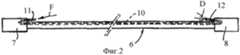
фиг.2 - коммутационный шнур передачи системы обработки информации, оборудованный согласно изобретению оптическим волокном;figure 2 - patch cord transmission system information processing, equipped according to the invention with an optical fiber;
фиг. 3 - аксонометрическое изображение зоны конца шнура с указанием средств введения света при использовании;FIG. 3 - axonometric image of the zone of the end of the cord indicating the means of introducing light when used;
фиг. 4 - продольный вид в частичном разрезе по линии IV-IV фиг.3;FIG. 4 is a longitudinal view in partial section along the line IV-IV of figure 3;
фиг. 5 - вариант шнура, оборудованный согласно изобретению двумя оптическими волокнами.FIG. 5 is a variant of a cord equipped according to the invention with two optical fibers.
Фиг.1 изображает схематически коммутационный шкаф средств обработки информации, обозначенный в целом позицией 2. Это коммутационный шкаф содержит техническое обеспечение 3, 4 и 5 обработки информации, активное или в качестве распределителя, соединенное между собой посредством коммутационных шнуров 6, обычно в большом количестве. Известным образом каждый коммутационный шнур имеет на своих обоих концах разъемы соответственно 7 и 8, такие как стандартные разъемы, например, типа «RJ 45», обеспечивающие соединение аппаратного обеспечения 3, 4 и 5 обработки информации - см. также фиг.2.Figure 1 depicts schematically a wiring closet for information processing means, indicated generally by 2. This wiring closet contains
Согласно изобретению и как показано на фиг.2-4, каждый коммутационный шнур 6 имеет помимо классических электрических проводников 9, идущих от одного разъема 7 к другому разъему 8, по меньшей мере, одно оптическое волокно 10, которое в свою очередь проложено по всей длине этого шнура 6 от одного его конца к другому.According to the invention and as shown in FIGS. 2-4, each
Оптическое волокно 10, помещенное под наружную оболочку шнура 6, имеет изогнутый первый конец 11, частично утопленный в первый разъем 7 шнура 6. Аналогичным образом оптическое волокно 10 имеет изогнутый второй конец 12, частично утопленный во второй разъем 8 шнура 6.The
Таким образом, ввод света в волокно по стрелке F, против изогнутого первого конца 11 оптического волокна 10 на конце шнура 6, оборудованного первым разъемом 7, сопровождается световым рассеянием D через второй изогнутый конец 12 оптического волокна 10. Второй конец 12 оптического волокна 10 легко определяем по световому сигналу, при желании цветному, и это без риска ошибки и без необходимости отключения шнура 6, даже если он окружен большим числом других подобных шнуров.Thus, the introduction of light into the fiber in the direction of the arrow F, against the curved
Для осуществления ввода света в волокно на конце шнура 6 здесь предусмотрено переносное средство, обозначенное в целом позицией 13, показанное на фиг.1 и рассмотренное детально на фиг. 3 и 4. Средство 13 ввода света в волокно включает корпус 14 для помещения источника питания 15, например, состоящего из одной или нескольких электрических батареек. Корпус продолжен гибким удлиненным элементом 16, на свободном конце которого помещена маленькая электрическая лампочка 17, питаемая источником 15 питания, например, одной или несколькими электрическими батарейками, или другой источник светового излучения. На своем свободном конце гибкий удлиненный элемент 16 оборудован еще одним полым концевым элементом 18 конической формы, разрезанным вдоль, что дает возможность охватить им конец шнура 6 около разъема 7 и или на этом разъеме 7. Конический концевой элемент 18 имеет отражающую внутреннюю поверхность.To implement the introduction of light into the fiber at the end of the
Таким образом, средство 13 ввода света в волокно может быть установлено на первом конце выбранного шнура 6, затем после включения электрической лампочки 17 излучаемый световой пучок концентрируется на торце 11 оптического волокна 10, принадлежащего единственному выбранному шнуру 6.Thus, the
Корпус 14 средства 13 ввода света в волокно включает, кроме того, преимущественно, зажим или другое средство 19 крепления, как отмечено на фиг.1, дающее возможность временного крепления его на шнуре 6 или на части коммутационного шкафа 2.The
Фиг. 5 изображает вариант выполнения устройства согласно изобретению, в котором два оптических волокна 10а и 10b расположены параллельно в единственном шнуре 6. На одном конце шнура 6, оборудованном первым разъемом 7, концы соответственно 11а, 11b обоих оптических волокон 10а и 10b изогнуты в диаметрально противоположных направлениях. Кроме того, на другом конце шнура 6, оборудованном вторым разъемом 8, концы соответственно 12а, 12b двух оптических волокон 10а и 10b изогнуты в диаметрально противоположных направлениях. Следовательно, независимо от ориентации разъемов 7 и 8 можно легко обнаружить соответственно на обоих концах шнура 6 по меньшей мере, один конец 11а, 11b оптического волокна, доступный для ввода в него света и, по меньшей мере, один видимый конец 12а, 12b оптического волокна, способный излучать световой сигнал, который будет правильно замечен.FIG. 5 shows an embodiment of the device according to the invention, in which two
В рамках настоящего изобретения возможны различные модификации, которые не удаляются от существа изобретения так, как оно определено в прилагаемой формуле изобретения. При этом устройство согласно изобретению можно модифицировать, например:In the framework of the present invention, various modifications are possible that are not removed from the essence of the invention as defined in the attached claims. Moreover, the device according to the invention can be modified, for example:
- встраивая большее или меньшее число оптических волокон внутрь шнуров или на их периферии;- embedding more or less optical fibers inside the cords or on their periphery;
- используя другие средства ввода света в оптические волокна;- using other means of introducing light into optical fibers;
- применяя устройство для шнуров, проводов, кабелей и других соединителей всех типов или также для трубопроводов вязких веществ;- using the device for cords, wires, cables and other connectors of all types or also for pipelines of viscous substances;
- изготавливая эти шнуры с электрическими разъемами или системами соединения вязких веществ.- making these cords with electrical connectors or systems for connecting viscous substances.
Claims (6)
Translated fromRussianApplications Claiming Priority (2)
| Application Number | Priority Date | Filing Date | Title |
|---|---|---|---|
| FR00/02865 | 2000-03-06 | ||
| FR0002865AFR2805920B1 (en) | 2000-03-06 | 2000-03-06 | VISUAL IDENTIFICATION DEVICE FOR WIRING OR CONDUITS |
Publications (2)
| Publication Number | Publication Date |
|---|---|
| RU2002126570A RU2002126570A (en) | 2004-04-20 |
| RU2294001C2true RU2294001C2 (en) | 2007-02-20 |
Family
ID=8847776
Family Applications (1)
| Application Number | Title | Priority Date | Filing Date |
|---|---|---|---|
| RU2002126570/28ARU2294001C2 (en) | 2000-03-06 | 2001-01-17 | Device for visual identification of cable wiring or pipelines |
Country Status (19)
| Country | Link |
|---|---|
| US (1) | US6906505B2 (en) |
| EP (1) | EP1261889B1 (en) |
| JP (1) | JP4686097B2 (en) |
| CN (1) | CN1232854C (en) |
| AT (1) | ATE327520T1 (en) |
| AU (1) | AU782531B2 (en) |
| BR (1) | BR0109007B1 (en) |
| CA (1) | CA2401876C (en) |
| CY (1) | CY1105472T1 (en) |
| DE (1) | DE60119903T2 (en) |
| DK (1) | DK1261889T3 (en) |
| ES (1) | ES2264971T3 (en) |
| FR (1) | FR2805920B1 (en) |
| HU (1) | HUP0300041A2 (en) |
| IL (2) | IL151569A0 (en) |
| PT (1) | PT1261889E (en) |
| RU (1) | RU2294001C2 (en) |
| WO (1) | WO2001067150A1 (en) |
| ZA (1) | ZA200206907B (en) |
Cited By (1)
| Publication number | Priority date | Publication date | Assignee | Title |
|---|---|---|---|---|
| RU2561798C1 (en)* | 2014-05-15 | 2015-09-10 | Акционерное общество "Военно-промышленная корпорация "Научно-производственное объединение машиностроения" (АО "ВПК" "НПО Машиностроения") | Inspection method of targeting connection of pipelines of tank pressurisation system of silo-based liquid-propellant missiles |
Families Citing this family (52)
| Publication number | Priority date | Publication date | Assignee | Title |
|---|---|---|---|---|
| TW563942U (en)* | 2002-08-29 | 2003-11-21 | Unixtar Technology Inc | Light-emitting connection cable of universal serial bus |
| US7298946B2 (en)* | 2004-12-22 | 2007-11-20 | Hewlett-Packard Development Company, L.P. | Multi-fiber cable for efficient manageability of optical system |
| US20060254803A1 (en)* | 2005-05-26 | 2006-11-16 | Dorffler Albertina H | Ornamental computer network cables |
| US7811119B2 (en) | 2005-11-18 | 2010-10-12 | Panduit Corp. | Smart cable provisioning for a patch cord management system |
| US7561060B2 (en)* | 2006-11-16 | 2009-07-14 | International Business Machines Corporation | Electroluminescent data cable identification and computer system diagnostics |
| FR2909186B1 (en)* | 2006-11-24 | 2009-01-09 | Patrice Brunet | DEVICE FOR VISUAL REPERAGE OF CABLES OR CONDUITS OF ALL THEIR LENGTH. |
| JP2008153030A (en)* | 2006-12-15 | 2008-07-03 | Toko Electrical Construction Co Ltd | Cable with identification function |
| US8477031B2 (en) | 2007-10-19 | 2013-07-02 | Panduit Corp. | Communication port identification system |
| DE502008002202D1 (en)* | 2008-01-28 | 2011-02-17 | Siemens Ag | Arrangement with two connection units connected via a cable |
| JP5341920B2 (en) | 2008-02-21 | 2013-11-13 | パンドウィット・コーポレーション | Intelligent interconnect and cross-connect patching system |
| US8102169B2 (en)* | 2008-07-25 | 2012-01-24 | International Business Machines Corporation | Cable tracing system and method for cable management |
| US8306935B2 (en) | 2008-12-22 | 2012-11-06 | Panduit Corp. | Physical infrastructure management system |
| EP3301767B1 (en) | 2008-12-31 | 2020-11-04 | Panduit Corp | Patch cord with insertion detection and light illumination capabilities |
| GB0901544D0 (en)* | 2009-01-30 | 2009-03-11 | Trojan Services Ltd | A combined cable trough and walkway |
| US8128428B2 (en) | 2009-02-19 | 2012-03-06 | Panduit Corp. | Cross connect patch guidance system |
| JP2010231144A (en)* | 2009-03-30 | 2010-10-14 | Fujikura Ltd | Optical fiber with connector |
| US8314603B2 (en)* | 2009-08-05 | 2012-11-20 | Realm Communications Group, Inc. | Network cable with tracer optical waveguide |
| EP2659550B1 (en)* | 2010-12-28 | 2021-09-08 | Rit Tech (Intelligence Solutions) Ltd. | Two-part modular connector comprising unique identification number of communication port |
| US9308323B2 (en) | 2011-11-15 | 2016-04-12 | Smiths Medical Asd, Inc. | Systems and methods for illuminated medical tubing detection and management indicating a characteristic of at least one infusion pump |
| US9308051B2 (en) | 2011-11-15 | 2016-04-12 | Smiths Medical Asd, Inc. | Illuminated tubing set |
| US8620123B2 (en) | 2012-02-13 | 2013-12-31 | Corning Cable Systems Llc | Visual tracer system for fiber optic cable |
| US9429731B2 (en) | 2013-08-12 | 2016-08-30 | Corning Optical Communications LLC | Optical fiber cable assembly comprising optical tracer fiber |
| FR3012249A1 (en) | 2013-10-22 | 2015-04-24 | Bull Sas | CABLE NETWORK COMPRISING A VISUAL REFERENCE DEVICE AND VISUAL TERMINAL SCREENING DEVICE FOR NETWORK CABLE. |
| CN105278046A (en)* | 2014-07-23 | 2016-01-27 | 中兴通讯股份有限公司 | Object identification method and device |
| CN105511025B (en)* | 2014-10-20 | 2018-08-24 | 南京中兴新软件有限责任公司 | Quartz plastic composite fiber component, recognition methods and device |
| US10379309B2 (en) | 2014-11-18 | 2019-08-13 | Corning Optical Communications LLC | Traceable optical fiber cable and filtered viewing device for enhanced traceability |
| CN105824082B (en)* | 2015-01-06 | 2018-12-04 | 中国移动通信集团广西有限公司 | A kind of jumping fiber |
| GB2536194A (en) | 2015-02-11 | 2016-09-14 | Eaton Ind France Sas | Automatically deducing the electrical cabling between electrical devices |
| US10228526B2 (en) | 2015-03-31 | 2019-03-12 | Corning Optical Communications LLC | Traceable cable with side-emitting optical fiber and method of forming the same |
| US10101553B2 (en) | 2015-05-20 | 2018-10-16 | Corning Optical Communications LLC | Traceable cable with side-emitting optical fiber and method of forming the same |
| EP3326014A1 (en) | 2015-07-17 | 2018-05-30 | Corning Optical Communications LLC | Systems and methods for tracing cables and cables for such systems and methods |
| EP3325876A1 (en) | 2015-07-17 | 2018-05-30 | Corning Optical Communications LLC | Systems and methods for traceable cables |
| KR20150118936A (en) | 2015-09-30 | 2015-10-23 | 손제왕 | Tracking System for Cable Line |
| US10101545B2 (en)* | 2015-10-30 | 2018-10-16 | Corning Optical Communications LLC | Traceable cable assembly and connector |
| PL416373A1 (en)* | 2016-03-03 | 2017-09-11 | Fibrain Spółka Z Ograniczoną Odpowiedzialnością | Hybrid telecommunication cable for data transmission |
| PL416372A1 (en)* | 2016-03-03 | 2017-09-11 | Fibrain Spółka Z Ograniczoną Odpowiedzialnością | Hybrid telecommunication cable for data transmission |
| CN109154701A (en)* | 2016-04-08 | 2019-01-04 | 康宁研究与开发公司 | With light structures and for carrying the traceable fiber optical cable assembly from the tracking optical fiber of the received light of light originating device |
| WO2017176828A2 (en)* | 2016-04-08 | 2017-10-12 | Corning Optical Communications LLC | Traceable fiber optic cable assembly with illumination structure and tracing optical fibers for carrying light received from a light launch device |
| US10107983B2 (en) | 2016-04-29 | 2018-10-23 | Corning Optical Communications LLC | Preferential mode coupling for enhanced traceable patch cord performance |
| CN105785516A (en)* | 2016-04-29 | 2016-07-20 | 中航光电科技股份有限公司 | Cable end testing device and calibration head thereof |
| KR101701708B1 (en)* | 2016-07-25 | 2017-02-03 | 주식회사 체크올 | Led lan cable connecter capable of transmitting high rate data and led lan cable capable of transmitting high rate data and led lan cable capabl system capable of transmitting high rate data |
| US10222560B2 (en)* | 2016-12-21 | 2019-03-05 | Corning Research & Development Corporation | Traceable fiber optic cable assembly with fiber guide and tracing optical fibers for carrying light received from a light launch device |
| US10234614B2 (en) | 2017-01-20 | 2019-03-19 | Corning Research & Development Corporation | Light source assemblies and systems and methods with mode homogenization |
| JP6533254B2 (en)* | 2017-06-09 | 2019-06-19 | 岡野電線株式会社 | Fiber optic cable |
| US10539758B2 (en) | 2017-12-05 | 2020-01-21 | Corning Research & Development Corporation | Traceable fiber optic cable assembly with indication of polarity |
| US10539747B2 (en) | 2017-12-05 | 2020-01-21 | Corning Research & Development Corporation | Bend induced light scattering fiber and cable assemblies and method of making |
| JP6945688B2 (en)* | 2019-02-01 | 2021-10-06 | 岡野電線株式会社 | Fiber optic cable |
| JP6749435B2 (en)* | 2019-02-01 | 2020-09-02 | 岡野電線株式会社 | Fiber optic cable |
| FR3095051A1 (en)* | 2019-04-12 | 2020-10-16 | Folan | SIGNAL TRANSPORT CORD INCLUDING A MEANS OF TRACKING OF AT LEAST ONE CONNECTOR INCLUDED IN THIS CORD |
| US11698481B2 (en)* | 2020-10-26 | 2023-07-11 | Eminent Technologies Company, LLC | Traceable fiber using ferrule and cap at fan-out kit |
| US11327253B1 (en)* | 2020-10-26 | 2022-05-10 | Eminent Technologies Company, LLC | Traceable fiber using light pipe at fan-out kit of fiber optics cable |
| US11333815B1 (en)* | 2020-10-26 | 2022-05-17 | Eminent Technologies Company, LLC | Traceable fiber using slotted light pipe at fan-out kit of fiber optics cable |
Citations (5)
| Publication number | Priority date | Publication date | Assignee | Title |
|---|---|---|---|---|
| SU1387050A1 (en)* | 1983-10-19 | 1988-04-07 | Государственный проектно-конструкторский и научно-исследовательский институт по автоматизации угольной промышленности "Гипроуглеавтоматизация" | Cable power transmission line with protection unit |
| RU2034189C1 (en)* | 1990-05-17 | 1995-04-30 | Кофлексип | Flexible pipe line for transporting matter under pressure |
| GB2270992B (en)* | 1992-08-04 | 1995-12-20 | Pirelli General Plc | Cables having electrical conductors and optical fibres |
| RU2066871C1 (en)* | 1991-07-08 | 1996-09-20 | Казовский Наум Иосифович | Combination cable for transmission of optical and electric signals |
| JP2000067662A (en)* | 1998-08-22 | 2000-03-03 | Masahiro Yokoyama | Electric wire |
Family Cites Families (18)
| Publication number | Priority date | Publication date | Assignee | Title |
|---|---|---|---|---|
| US3706134A (en)* | 1970-08-04 | 1972-12-19 | Amp Inc | Optical aid |
| US4074187A (en)* | 1976-11-30 | 1978-02-14 | Miller David H | Cable tester for multi-pair shielded cables |
| IT1175835B (en)* | 1984-04-19 | 1987-07-15 | Pirelli Cavi Spa | SUBMARINE CABLE FOR FIBER OPTIC TELECOMMUNICATIONS |
| JPS61161827U (en)* | 1985-03-27 | 1986-10-07 | ||
| US4695127A (en)* | 1985-03-27 | 1987-09-22 | Cooper Industries, Inc. | Hybrid coaxial-optical cable and method of use |
| US4748415A (en)* | 1986-04-29 | 1988-05-31 | Paramagnetic Logging, Inc. | Methods and apparatus for induction logging in cased boreholes |
| JPH01200209A (en) | 1988-02-04 | 1989-08-11 | Takashi Mori | solar collector |
| DE4042317A1 (en) | 1990-12-28 | 1992-07-02 | Defa Studio Babelsberg Gmbh I | Light conductor identification method - measuring intensity of light passing through from non-ordered end to ordered end |
| US5305405A (en)* | 1993-02-25 | 1994-04-19 | Adc Telecommunications, Inc. | Patch cord |
| CN1095484A (en) | 1993-05-17 | 1994-11-23 | 董国婵 | Optical cable port ONLINE RECOGNITION method and port can be discerned optical cable |
| US5353367A (en)* | 1993-11-29 | 1994-10-04 | Northern Telecom Limited | Distribution frame and optical connector holder combination |
| US5463706A (en)* | 1994-02-16 | 1995-10-31 | Thomas & Betts Corporation | Light traceable transmission conduit assembly |
| US5666453A (en)* | 1994-07-15 | 1997-09-09 | Roy Witte | Fiber optic jumper cables and tracing method using same |
| FR2725796B1 (en)* | 1994-10-14 | 1997-01-03 | Alcatel Nv | METHOD FOR FIXING OPTICAL FIBER WITH POLARIZATION HOLD AND FERRULE FOR SUCH FIBER |
| US5764043A (en)* | 1996-12-20 | 1998-06-09 | Siecor Corporation | Traceable patch cord and connector assembly and method for locating patch cord ends |
| US6064210A (en)* | 1997-11-14 | 2000-05-16 | Cedar Bluff Group Corporation | Retrievable resistivity logging system for use in measurement while drilling |
| US6208796B1 (en)* | 1998-07-21 | 2001-03-27 | Adc Telecommunications, Inc. | Fiber optic module |
| US6633164B2 (en)* | 2000-01-24 | 2003-10-14 | Shell Oil Company | Measuring focused through-casing resistivity using induction chokes and also using well casing as the formation contact electrodes |
- 2000
- 2000-03-06FRFR0002865Apatent/FR2805920B1/ennot_activeExpired - Lifetime
- 2001
- 2001-01-17ATAT01907611Tpatent/ATE327520T1/enactive
- 2001-01-17ILIL15156901Apatent/IL151569A0/enactiveIP Right Grant
- 2001-01-17CNCNB018061982Apatent/CN1232854C/ennot_activeExpired - Lifetime
- 2001-01-17PTPT01907611Tpatent/PT1261889E/enunknown
- 2001-01-17RURU2002126570/28Apatent/RU2294001C2/enactive
- 2001-01-17AUAU35534/01Apatent/AU782531B2/ennot_activeExpired
- 2001-01-17DKDK01907611Tpatent/DK1261889T3/enactive
- 2001-01-17BRBRPI0109007-0Apatent/BR0109007B1/ennot_activeIP Right Cessation
- 2001-01-17HUHU0300041Apatent/HUP0300041A2/enunknown
- 2001-01-17EPEP01907611Apatent/EP1261889B1/ennot_activeExpired - Lifetime
- 2001-01-17USUS10/220,933patent/US6906505B2/ennot_activeExpired - Lifetime
- 2001-01-17ESES01907611Tpatent/ES2264971T3/ennot_activeExpired - Lifetime
- 2001-01-17WOPCT/FR2001/000144patent/WO2001067150A1/enactiveIP Right Grant
- 2001-01-17DEDE60119903Tpatent/DE60119903T2/ennot_activeExpired - Lifetime
- 2001-01-17JPJP2001566068Apatent/JP4686097B2/ennot_activeExpired - Lifetime
- 2001-01-17CACA002401876Apatent/CA2401876C/ennot_activeExpired - Lifetime
- 2002
- 2002-08-28ZAZA200206907Apatent/ZA200206907B/enunknown
- 2002-09-02ILIL151569Apatent/IL151569A/enunknown
- 2006
- 2006-08-18CYCY20061101155Tpatent/CY1105472T1/enunknown
Patent Citations (5)
| Publication number | Priority date | Publication date | Assignee | Title |
|---|---|---|---|---|
| SU1387050A1 (en)* | 1983-10-19 | 1988-04-07 | Государственный проектно-конструкторский и научно-исследовательский институт по автоматизации угольной промышленности "Гипроуглеавтоматизация" | Cable power transmission line with protection unit |
| RU2034189C1 (en)* | 1990-05-17 | 1995-04-30 | Кофлексип | Flexible pipe line for transporting matter under pressure |
| RU2066871C1 (en)* | 1991-07-08 | 1996-09-20 | Казовский Наум Иосифович | Combination cable for transmission of optical and electric signals |
| GB2270992B (en)* | 1992-08-04 | 1995-12-20 | Pirelli General Plc | Cables having electrical conductors and optical fibres |
| JP2000067662A (en)* | 1998-08-22 | 2000-03-03 | Masahiro Yokoyama | Electric wire |
Cited By (1)
| Publication number | Priority date | Publication date | Assignee | Title |
|---|---|---|---|---|
| RU2561798C1 (en)* | 2014-05-15 | 2015-09-10 | Акционерное общество "Военно-промышленная корпорация "Научно-производственное объединение машиностроения" (АО "ВПК" "НПО Машиностроения") | Inspection method of targeting connection of pipelines of tank pressurisation system of silo-based liquid-propellant missiles |
Also Published As
| Publication number | Publication date |
|---|---|
| BR0109007A (en) | 2003-06-03 |
| CN1232854C (en) | 2005-12-21 |
| ES2264971T3 (en) | 2007-02-01 |
| DE60119903D1 (en) | 2006-06-29 |
| ATE327520T1 (en) | 2006-06-15 |
| CA2401876C (en) | 2009-12-22 |
| EP1261889A1 (en) | 2002-12-04 |
| CA2401876A1 (en) | 2001-09-13 |
| DK1261889T3 (en) | 2006-09-25 |
| CY1105472T1 (en) | 2010-07-28 |
| FR2805920B1 (en) | 2004-01-30 |
| JP4686097B2 (en) | 2011-05-18 |
| DE60119903T2 (en) | 2007-04-26 |
| HUP0300041A2 (en) | 2003-05-28 |
| AU3553401A (en) | 2001-09-17 |
| US6906505B2 (en) | 2005-06-14 |
| PT1261889E (en) | 2006-09-29 |
| FR2805920A1 (en) | 2001-09-07 |
| WO2001067150A1 (en) | 2001-09-13 |
| JP2003526813A (en) | 2003-09-09 |
| BR0109007B1 (en) | 2014-01-07 |
| CN1416534A (en) | 2003-05-07 |
| HK1053513A1 (en) | 2003-10-24 |
| US20030152344A1 (en) | 2003-08-14 |
| IL151569A0 (en) | 2003-04-10 |
| AU782531B2 (en) | 2005-08-04 |
| EP1261889B1 (en) | 2006-05-24 |
| IL151569A (en) | 2006-08-20 |
| ZA200206907B (en) | 2003-07-02 |
Similar Documents
| Publication | Publication Date | Title |
|---|---|---|
| RU2294001C2 (en) | Device for visual identification of cable wiring or pipelines | |
| US7029137B2 (en) | Cable having an illuminating tracer element mounted thereon | |
| US5305405A (en) | Patch cord | |
| CN104932065B (en) | Without the fibre system of pcb board and optical fiber wiring method in fiber distribution module | |
| US8314603B2 (en) | Network cable with tracer optical waveguide | |
| US6347172B1 (en) | Cable having side-emitting fiber under transparent or translucent cable jacket | |
| CN101188350B (en) | Marking device for visually marking cable or pipeline in whole course | |
| US7194183B2 (en) | Modular receptacle assembly and interface with integral optical indication | |
| US20180172925A1 (en) | Traceable end point cable assembly having a tracing waveguide | |
| RU2002126570A (en) | VISUAL IDENTIFICATION OF CABLE WIRING OR PIPELINES | |
| CN203422501U (en) | Optical fiber connector having radio frequency identification tag | |
| CN105792029B (en) | Intelligent ODN (optical distribution network) identification system and device | |
| CN104953313A (en) | Optical fiber connection device for electric connection, electric connector and control wire | |
| US20040213522A1 (en) | Fiber optic cable identification kit and its method | |
| EP3211465B1 (en) | Quartz plastic composite optical fiber assembly, recognition method and device | |
| KR101602621B1 (en) | Device for identifying opitcal line with opticlal fiber calbes | |
| US9946038B1 (en) | Cable tracing type jumper cable | |
| CN202631788U (en) | Optical fiber jumper wire | |
| HK1053513B (en) | Device for visual identification of cables or conduits | |
| US6912329B1 (en) | Fiber color detector method and apparatus | |
| JP2004096846A (en) | Wiring tracking device | |
| KR101731585B1 (en) | communication line identification device |