RU2290884C1 - Surgical apparatus for putting seams on - Google Patents
Surgical apparatus for putting seams onDownload PDFInfo
- Publication number
- RU2290884C1 RU2290884C1RU2005118045/14ARU2005118045ARU2290884C1RU 2290884 C1RU2290884 C1RU 2290884C1RU 2005118045/14 ARU2005118045/14 ARU 2005118045/14ARU 2005118045 ARU2005118045 ARU 2005118045ARU 2290884 C1RU2290884 C1RU 2290884C1
- Authority
- RU
- Russia
- Prior art keywords
- pin
- frame
- profiled
- pusher
- lever
- Prior art date
Links
- 239000011159matrix materialSubstances0.000claimsabstractdescription13
- 238000012423maintenanceMethods0.000abstractdescription2
- 230000002035prolonged effectEffects0.000abstractdescription2
- 241001236644LaviniaSpecies0.000abstract1
- 230000000694effectsEffects0.000abstract1
- 239000000126substanceSubstances0.000abstract1
- 210000000056organAnatomy0.000description4
- 238000001356surgical procedureMethods0.000description4
- 239000004744fabricSubstances0.000description3
- 230000003872anastomosisEffects0.000description2
- 238000009434installationMethods0.000description2
- 238000000034methodMethods0.000description2
- 208000027418Wounds and injuryDiseases0.000description1
- 230000003187abdominal effectEffects0.000description1
- 230000006978adaptationEffects0.000description1
- 230000000712assemblyEffects0.000description1
- 238000000429assemblyMethods0.000description1
- 239000008280bloodSubstances0.000description1
- 210000004369bloodAnatomy0.000description1
- 230000006835compressionEffects0.000description1
- 238000007906compressionMethods0.000description1
- 230000007797corrosionEffects0.000description1
- 238000005260corrosionMethods0.000description1
- 230000007547defectEffects0.000description1
- 230000005489elastic deformationEffects0.000description1
- 230000002349favourable effectEffects0.000description1
- 210000003811fingerAnatomy0.000description1
- 210000001035gastrointestinal tractAnatomy0.000description1
- 208000014674injuryDiseases0.000description1
- 230000007774longtermEffects0.000description1
- 239000000463materialSubstances0.000description1
- 230000002980postoperative effectEffects0.000description1
- 238000000926separation methodMethods0.000description1
- 238000009958sewingMethods0.000description1
- 210000000115thoracic cavityAnatomy0.000description1
- 210000003813thumbAnatomy0.000description1
- 230000017423tissue regenerationEffects0.000description1
- 230000008733traumaEffects0.000description1
Images


Landscapes
- Surgical Instruments (AREA)
Abstract
Description
Translated fromRussianИзобретение относится к области медицинской техники, а именно к хирургическим сшивающим аппаратам для механического соединения органов и тканей при хирургических операциях. Применение сшивающих аппаратов уменьшает потерю крови и травматизацию тканей, повышает асептичность операции, упрощает процесс сшивания и обеспечивает более точную адаптацию краев соединяемых тканей, сокращает время наложения шва и операции в целом, что создает благоприятные условия для регенерации тканей в послеоперационном периоде (Краткая медицинская энциклопедия. В 3-х т. Т.3. М.: "Советская энциклопедия". 1990. 560 с.).The invention relates to the field of medical equipment, namely to surgical staplers for the mechanical connection of organs and tissues during surgical operations. The use of staplers reduces blood loss and tissue trauma, increases the asepticity of the operation, simplifies the stitching process and provides a more accurate adaptation of the edges of the connected tissues, reduces the time for suturing and surgery in general, which creates favorable conditions for tissue regeneration in the postoperative period (Brief Medical Encyclopedia. In 3 volumes of Vol. 3. M.: “Soviet Encyclopedia. 1990. 560 p.).
Заявляемое техническое решение относится к аппаратам, корпус с приводами которых располагается относительно кассеты и матрицы перпендикулярно и посредине в виде буквы Т и прошивание тканей выполняют в два этапа: сначала кассета со скобками придавливается к матрице приводом скобочного корпуса, затем скобки выталкиваются из кассеты приводом подвижного толкателя и загибаются в лунках матрицы.The claimed technical solution relates to apparatuses, the case with the drives of which are located relative to the cartridge and the matrix perpendicularly and in the middle in the form of the letter T and the sewing of fabrics is carried out in two stages: first, the cartridge with brackets is pressed to the matrix by the drive of the bracket body, then the brackets are ejected from the cartridge by the drive of the movable pusher and bend in the holes of the matrix.
Известны различные технические решения аппаратов аналогичного назначения, используемых в практической хирургии и выпускаемых отечественной медицинской промышленностью. К ним относятся ушиватель органов УО моделей 227 и 228, включающие упорный корпус, скобочный корпус, толкатель с пластинами, гайку, штурвал, магазин и ограничитель. Конструкция направляющих узлов скобочного корпуса и магазина аппарата типа УО усложняет их сборку и разборку, а так же не позволяет заменить магазин, при необходимости, непосредственно при проведении операции не вынимая аппарат из зоны раны.There are various technical solutions of devices of a similar purpose used in practical surgery and produced by the domestic medical industry. These include the UO organ stapler of models 227 and 228, including a thrust housing, a bracket body, a pusher with plates, a nut, a steering wheel, a magazine and a limiter. The design of the guide assemblies of the bracket body and the magazine of the UO type apparatus complicates their assembly and disassembly, and also does not allow replacing the magazine, if necessary, directly during the operation without removing the apparatus from the wound area.
Конструкция хирургического сшивающего аппарата для наложения линейных швов (Патент США 3494533, 227-19, 1970) включает: упорный корпус с замкнутой прямоугольной рамой, с которой взаимодействует приводная скобочная головка, содержащая магазин для скобок и приводной толкатель. Рама состоит из П-образной части, на одной из губок которой смонтирована матрица и съемная боковая (фиксатор), связывающая губки П-образной части. Замкнутая рама может быть раскрыта сбоку от губки с матрицей. Конструкция рамы сложна и неудобна в работе.The design of a surgical stapler for suturing linear sutures (US Pat. No. 3,494,533, 227-19, 1970) includes: a thrust housing with a closed rectangular frame, with which a drive bracket head comprising a magazine for brackets and a drive pusher interacts. The frame consists of a U-shaped part, on one of the lips of which the matrix is mounted and a removable side (retainer) connecting the lips of the U-shaped part. A closed frame can be opened to the side of the sponge with the matrix. The design of the frame is complex and inconvenient in operation.
Особенностью хирургического сшивающего аппарата наложения линейных швов (Авт. св. СССР 886899, А 61 В 17/072), принятого за прототип, как наиболее близкого по конструктивным и функциональным признакам к заявленному техническому решению, является то, что в аппарате фиксатор рамы имеет упоры, охватывающие консольные концы верхней и нижней губок П-образной части рамы, на концах губок предусмотрены пазы и упоры, взаимодействующие с фиксатором, а П-образная часть рамы выполнена пружинящей. Величина изгиба консольных концов губок рассчитана на упругую деформацию П-образной части рамы на величину, равную или большую высоты фиксаторов. При этом совершенно не принимается во внимание то, что в середине верхней губки рамы предусмотрено сквозное отверстие для монтажа штока, что ставит под сомнение использование пружинящих свойств консоли верхней губки. При длительной эксплуатации аппарата, в результате многократных нагрузок возможна потеря первоначально заложенной величины жесткости рамы. Аппарат не позволяет проводить сшивание без фиксатора, который должен устанавливаться непосредственно при проведении операции, что является большим неудобством для хирурга. При установке фиксатор зацепляется за выступ упорного корпуса, затем поворачивается и пазом фиксируется за выступ упорного корпуса. Для съема фиксатора рамы необходимо средний палец руки установить на нижний торец фиксатора в области нижней губки, а большой палец - на верхнюю губку, прислонив его к рычагу фиксатора. Встречное сжатие губок приводит к повороту и разъединению фиксатора. Фиксация фиксатора на губках очень усложнена. Причем использование аппарата в работе без фиксатора недопустимо из-за недостаточной жесткости рамы упорного корпуса.A feature of the surgical suturing apparatus for applying linear sutures (Aut. St. USSR 886899, A 61
Цель технического результата - упрощение сборки и разборки конструкции рамы аппарата, повышение ее надежности и удобство обслуживания при проведении операции и увеличение его долговечности эксплуатации.The purpose of the technical result is to simplify the assembly and disassembly of the apparatus frame structure, increase its reliability and ease of maintenance during the operation and increase its operation life.
Поставленная цель достигается тем, что, согласно изобретению, фиксатор выполнен в виде профилированной пластины с направляющей в виде крестообразного поперечного сечения, а консоль фиксатора в направлении нижней губки снабжен штифтом, в верхней и нижней губках предусмотрены профилированные сквозные паз крестообразного поперечного сечения и отверстие соответственно, причем удлиненный рычаг представляет последовательность под углом ориентированных друг к другу разнонаправленных отрезков пластины, конец каждого из которых является началом следующего, а П-образная часть рамы имеет жесткую конструкцию.This goal is achieved by the fact that, according to the invention, the latch is made in the form of a profiled plate with a guide in the form of a cross-shaped cross section, and the latch console in the direction of the lower jaw is provided with a pin, in the upper and lower jaws are provided profiled through the groove of the cross-shaped cross section and the hole, respectively, moreover, the elongated lever represents a sequence at an angle oriented to each other in different directions of the plate, the end of each of which is at the beginning of the next, and the U-shaped part of the frame has a rigid structure.
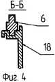
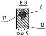
На фиг.1 - изображен хирургический аппарат для наложения швов, вид сверху; на фиг.2 - вид сбоку; на фиг.3 - сечение А-А фиг.1; на фиг.4 - сечение Б-Б на фиг.1; на фиг.5 - сечение В-В на фиг.1; на фиг.6 - сечение Г-Г на фиг.1.Figure 1 - shows a surgical apparatus for suturing, top view; figure 2 is a side view; figure 3 is a section aa of figure 1; figure 4 is a section bB in figure 1; figure 5 - section bb in figure 1; figure 6 is a cross section GG in figure 1.
Конструкция аппарата включает: упорный корпус 1 с рамой 2, матрицу 3, смонтированную на упорном корпусе 1, скобочный корпус 4, магазин 5, фиксатор 6. удлиненный рычаг 7, гайку 8, винт 9, рукоятку 10, толкатель 11, шток упорного корпуса 12, губки 13 и 14 рамы 2, штифт фиксатора 15, сквозное отверстие 16 в нижней губке для штифта фиксатора 6, профилированный паз в верхней губке 17, направляющая фиксатора и скобочного корпуса 18. Замкнутая прямоугольная рама 2 состоит из П-образной части с верхней 13 и нижней 14 губками, консоли которых соединены съемным фиксатором 6, соединенным с удлиненным рычагом 7.The apparatus design includes: a
Фиксатор 6 представляет собой утолщенную профилированную пластину с направляющей в виде крестообразного поперечного сечения с длиной не менее расстояния между верхней и нижней губками, на одном конце которого закреплен удлиненный рычаг 7, а на другом - штифт 15 круглого сечения с длиной не более толщины нижней губки 14. В теле верхней губки предусмотрен профилированный сквозной паз 17 крестообразного поперечного сечения, соответствующего форме направляющей фиксатора 6 и предназначен для возвратно-поступательного движения фиксатора 6 с удлиненным рычагом 7. В теле нижней губки 14 рамы просверлено сквозное отверстие 16 для фиксации штифта 15 фиксатора 6.The
Таким образом, конструктивно оформленная рама 2 с губками 13, 14 и фиксатором 6 образует замкнутую систему, практически не обладающей деформацией при рабочем режиме аппарата как замкнутом и разомкнутом положении рамы 2 упорного корпуса 1.Thus, a structurally designed frame 2 with
Удлиненный рычаг 7 представляет последовательность под углом ориентированных друг к другу разнонаправленных отрезков пластины, конец каждого из которых является началом следующего.The
Прочность ориентированной друг к другу верхней 13 и нижней 14 губок, боковой стороны П-образной рамы 2 упорного корпуса 1 определена с учетом работы хирурга без использования фиксатора и длительной эксплуатации аппарата, коррозионной усталости материала, из которого изготовлено изделие.The strength of the upper 13 and lower 14 jaws oriented to each other, the side of the U-shaped frame 2 of the
С рамой 2 взаимодействует упорный корпус 1 со штоком, имеющим продольный паз и поперечный поясок с прорезью (на чертеже не показано). В собранном аппарате в них установлены скобочный корпус 4 и гайка 8 в сборе с толкателем 11, магазином 5, крышкой (на чертеже не показано) и винтом 9. Соединение скобочного корпуса 4 с упорным корпусом 1 и фиксатором 6 осуществляется с помощью боковых пазов и выступов (на чертеже не показано) на скобочном корпусе 4, которые связываются с соответствующими им элементами на упорном корпусе 1 и фиксатора 6 после поворота гайки 8. Скобочный корпус 4 состоит из головки и штока с резьбовым хвостовиком (на чертеже не показано). Хвостовик штока имеет две резьбы: наружную левую и внутреннюю правую. С наружной резьбой связана гайка 8 привода скобочного корпуса 4. После установки в упорный корпус 1 гайку 8 и скобочный корпус 4 фиксируют от осевого перемещения поперечным пояском упорного корпуса 1, охватывающим кольцевую канавку гайки. В резьбовое отверстие скобочного корпуса 4 ввернут винт 9 привода толкателя 11. Последний состоит из головки с пластинами для выталкивания скобок из магазина 4 и штока с вилкой на конце. Паз вилки выполнен с расширением, обращенным в сторону штока скобочного корпуса. Магазин 5 содержит скобочные пазы для установки в них скобок. Он имеет продольный (снизу) и боковые фиксирующие выступы (на чертеже не показано), устанавливаемые в канавки на дне и боковых стенках головки скобочного корпуса 4. Крышка (на чертеже не показано) имеет выступы, которые вводятся в соответствующие пазы головки упорного корпуса 1. Крышка фиксирует магазин и головку толкателя в головке упорного корпуса 1. Винт 9 в передней части имеет упорную головку для перемещения толкателя, а в хвостовой части отверстие с пазами. В отверстие винта вставлена рукоятка 10 с выступами, соответствующими пазам. Хвостовая часть упорного корпуса 1 имеет с двух сторон канавки с боковыми стенками (на чертеже не показано), которые служат для контроля зазоров сшивания между магазином и матрицей.The
Принцип работы заявляемого технического решения и прототипа аналогичен. Различием являются детали рамы упорного корпуса. До работы аппарат должен полностью собран - рукоятка 10 снята, штифт фиксатора 15 отведен от нижней губки 14 на 10-15 мм, магазин 5 со скобками вставлен в головку скобочного корпуса 4. Аппарат подводится к сшиваемой ткани и последняя заводится в паз между матрицей 3 и магазином 5; при помощи удлиненного рычага 7 штифт фиксатора 15 вводится в сквозное отверстие 16 нижней губки 14. Гайкой 8 головка скобочного корпуса 4 с магазином 5 подводится к матрице 3. Вставляется рукоятка 10 в головку винта 9 и поворачивая винт 9 толкатель 11 перемещается и выдавливается из магазина 5 скобки. Последние упираются в лунки матрицы 3 и загибаются - происходит прошивание ткани. При необходимости лезвием скальпеля лишняя часть ткани срезается по кромке матрицы 3. Гайкой 8 головка скобочного корпуса 18 с магазином 5, а также фиксатор 6 с рычагом 7 отводится в первоначальное положение; затем аппарат убирается из зоны операции.The principle of operation of the proposed technical solution and prototype is similar. The difference is the details of the frame of the thrust housing. Before operation, the device must be fully assembled - the handle 10 is removed, the
Усиленная жесткость конструкции рамы 2 упорного корпуса 1 аппарата позволяет работать с фиксатором 6 и без него. При работе фиксатор 6 вставлен в направляющие пазы упорного корпуса 1 и для замыкания рамы необходимо только подвинуть рычаг 7 до упора, что хирургом проводится без затруднений.Reinforced structural rigidity of the frame 2 of the
Проведенный заявителем анализ уровня техники, включающий поиск по патентным и научно-техническим источникам информации, выявление источников, содержащих сведения об аналогах заявленного изобретения, позволил установить, что заявитель не обнаружил аналог, характеризующийся признаками, идентичными всем существенным признакам заявленного технического решения. Определение из перечня выявленных аналогов прототипа, как наиболее близкого по совокупности существенных признаков аналога, позволил выявить совокупность существенных по отношению к усматриваемому техническому результату отличительных признаков в заявленном хирургическом аппарате для наложения швов, изложенных в формуле изобретения. Следовательно, заявленное изобретение соответствует условию «новизна».An analysis of the prior art by the applicant, including a search by patent and scientific and technical sources of information, identification of sources containing information about analogues of the claimed invention, allowed to establish that the applicant did not find an analogue characterized by features identical to all the essential features of the claimed technical solution. The definition from the list of identified analogues of the prototype, as the closest in the set of essential features of the analogue, allowed us to identify the set of essential distinctive features in the claimed surgical apparatus for suturing, set forth in the claims. Therefore, the claimed invention meets the condition of "novelty."
Для проверки соответствия заявленного изобретения условию «изобретательский уровень» был проведен дополнительный поиск известных решений (Краткая медицинская энциклопедия: В 3-х т. М.: «Советская энциклопедия», 1990), совпадающих с отличительными от прототипа признаками заявленного хирургического сшивающего аппарата. Результаты поиска показали, что заявленное изобретение не вытекает для специалиста явным образом из известного уровня техники. Не известны конструктивные решения рамы аппарата, обеспечивающие достигнуть поставленную цель, что свидетельствует об удовлетворении критерия «изобретательский уровень».To verify the compliance of the claimed invention with the condition “inventive step”, an additional search was carried out for known solutions (Brief Medical Encyclopedia: In 3 volumes M: “Soviet Encyclopedia”, 1990), which coincided with the distinctive features of the claimed surgical stapler from the prototype. The search results showed that the claimed invention does not follow for a specialist explicitly from the prior art. Structural solutions of the apparatus frame are not known, which ensure the achievement of the goal, which indicates the satisfaction of the criterion of "inventive step".
Заявленное техническое решение позволяет повысить удобство подготовки аппарата к работе и предназначено для ушивания тканей или закрытых дефектов в стенках органов механическим швом; оно может применяться для наложения анастомозов между органами пищеварительного тракта методом «триангуляции» или при наложении анастомозов комбинированным швом - механическим в сочетании с ручным. Область применения - абдоминальная и торакальная хирургия, проктология и другие области детской и взрослой хирургии. Таким образом, предложенное решение удовлетворяет критерию изобретения «промышленная применимость».The claimed technical solution allows to increase the convenience of preparing the apparatus for work and is intended for suturing tissues or closed defects in the walls of organs with a mechanical suture; it can be used to apply anastomoses between the organs of the digestive tract by the method of "triangulation" or when applying anastomoses with a combined suture - mechanical in combination with manual. Scope - abdominal and thoracic surgery, proctology and other areas of pediatric and adult surgery. Thus, the proposed solution meets the criteria of the invention of "industrial applicability".
Claims (1)
Translated fromRussianPriority Applications (1)
| Application Number | Priority Date | Filing Date | Title |
|---|---|---|---|
| RU2005118045/14ARU2290884C1 (en) | 2005-08-18 | 2005-08-18 | Surgical apparatus for putting seams on |
Applications Claiming Priority (1)
| Application Number | Priority Date | Filing Date | Title |
|---|---|---|---|
| RU2005118045/14ARU2290884C1 (en) | 2005-08-18 | 2005-08-18 | Surgical apparatus for putting seams on |
Publications (1)
| Publication Number | Publication Date |
|---|---|
| RU2290884C1true RU2290884C1 (en) | 2007-01-10 |
Family
ID=37761081
Family Applications (1)
| Application Number | Title | Priority Date | Filing Date |
|---|---|---|---|
| RU2005118045/14ARU2290884C1 (en) | 2005-08-18 | 2005-08-18 | Surgical apparatus for putting seams on |
Country Status (1)
| Country | Link |
|---|---|
| RU (1) | RU2290884C1 (en) |
Cited By (16)
| Publication number | Priority date | Publication date | Assignee | Title |
|---|---|---|---|---|
| RU2720322C2 (en)* | 2015-09-02 | 2020-04-28 | ЭТИКОН ЭлЭлСи | Matrices of surgical staple ejectors |
| RU2727590C2 (en)* | 2015-08-26 | 2020-07-22 | ЭТИКОН ЭлЭлСи | Surgical brackets to minimize lateral inclination of bracket |
| US11213295B2 (en) | 2015-09-02 | 2022-01-04 | Cilag Gmbh International | Surgical staple configurations with camming surfaces located between portions supporting surgical staples |
| US11219456B2 (en) | 2015-08-26 | 2022-01-11 | Cilag Gmbh International | Surgical staple strips for permitting varying staple properties and enabling easy cartridge loading |
| US11246587B2 (en) | 2013-12-23 | 2022-02-15 | Cilag Gmbh International | Surgical cutting and stapling instruments |
| USD948043S1 (en) | 2016-06-24 | 2022-04-05 | Cilag Gmbh International | Surgical fastener |
| US11364028B2 (en) | 2013-12-23 | 2022-06-21 | Cilag Gmbh International | Modular surgical system |
| US11382624B2 (en) | 2015-09-02 | 2022-07-12 | Cilag Gmbh International | Surgical staple cartridge with improved staple driver configurations |
| US11510675B2 (en) | 2015-08-26 | 2022-11-29 | Cilag Gmbh International | Surgical end effector assembly including a connector strip interconnecting a plurality of staples |
| US11684367B2 (en) | 2016-12-21 | 2023-06-27 | Cilag Gmbh International | Stepped assembly having and end-of-life indicator |
| US11690619B2 (en) | 2016-06-24 | 2023-07-04 | Cilag Gmbh International | Staple cartridge comprising staples having different geometries |
| US11786246B2 (en) | 2016-06-24 | 2023-10-17 | Cilag Gmbh International | Stapling system for use with wire staples and stamped staples |
| US11896223B2 (en) | 2013-12-23 | 2024-02-13 | Cilag Gmbh International | Surgical cutting and stapling instruments with independent jaw control features |
| US11963682B2 (en) | 2015-08-26 | 2024-04-23 | Cilag Gmbh International | Surgical staples comprising hardness variations for improved fastening of tissue |
| US12137913B2 (en) | 2015-08-26 | 2024-11-12 | Cilag Gmbh International | Staple cartridge assembly comprising various tissue compression gaps and staple forming gaps |
| US12433590B2 (en) | 2016-06-24 | 2025-10-07 | Cilag Gmbh International | Stapling system for use with wire staples and stamped staples |
Citations (2)
| Publication number | Priority date | Publication date | Assignee | Title |
|---|---|---|---|---|
| US4573622A (en)* | 1984-10-19 | 1986-03-04 | United States Surgical Corporation | Surgical fastener applying apparatus with variable fastener arrays |
| WO1986002253A1 (en)* | 1984-10-19 | 1986-04-24 | United States Surgical Corporation | Surgical fastener applying apparatus with progressive application of fasteners |
- 2005
- 2005-08-18RURU2005118045/14Apatent/RU2290884C1/ennot_activeIP Right Cessation
Patent Citations (2)
| Publication number | Priority date | Publication date | Assignee | Title |
|---|---|---|---|---|
| US4573622A (en)* | 1984-10-19 | 1986-03-04 | United States Surgical Corporation | Surgical fastener applying apparatus with variable fastener arrays |
| WO1986002253A1 (en)* | 1984-10-19 | 1986-04-24 | United States Surgical Corporation | Surgical fastener applying apparatus with progressive application of fasteners |
Cited By (24)
| Publication number | Priority date | Publication date | Assignee | Title |
|---|---|---|---|---|
| US11583273B2 (en) | 2013-12-23 | 2023-02-21 | Cilag Gmbh International | Surgical stapling system including a firing beam extending through an articulation region |
| US11950776B2 (en) | 2013-12-23 | 2024-04-09 | Cilag Gmbh International | Modular surgical instruments |
| US11896223B2 (en) | 2013-12-23 | 2024-02-13 | Cilag Gmbh International | Surgical cutting and stapling instruments with independent jaw control features |
| US11779327B2 (en) | 2013-12-23 | 2023-10-10 | Cilag Gmbh International | Surgical stapling system including a push bar |
| US11246587B2 (en) | 2013-12-23 | 2022-02-15 | Cilag Gmbh International | Surgical cutting and stapling instruments |
| US11759201B2 (en) | 2013-12-23 | 2023-09-19 | Cilag Gmbh International | Surgical stapling system comprising an end effector including an anvil with an anvil cap |
| US11364028B2 (en) | 2013-12-23 | 2022-06-21 | Cilag Gmbh International | Modular surgical system |
| US11963682B2 (en) | 2015-08-26 | 2024-04-23 | Cilag Gmbh International | Surgical staples comprising hardness variations for improved fastening of tissue |
| US11219456B2 (en) | 2015-08-26 | 2022-01-11 | Cilag Gmbh International | Surgical staple strips for permitting varying staple properties and enabling easy cartridge loading |
| US12137913B2 (en) | 2015-08-26 | 2024-11-12 | Cilag Gmbh International | Staple cartridge assembly comprising various tissue compression gaps and staple forming gaps |
| US12035915B2 (en) | 2015-08-26 | 2024-07-16 | Cilag Gmbh International | Surgical staples comprising hardness variations for improved fastening of tissue |
| RU2727590C2 (en)* | 2015-08-26 | 2020-07-22 | ЭТИКОН ЭлЭлСи | Surgical brackets to minimize lateral inclination of bracket |
| US11510675B2 (en) | 2015-08-26 | 2022-11-29 | Cilag Gmbh International | Surgical end effector assembly including a connector strip interconnecting a plurality of staples |
| US11213295B2 (en) | 2015-09-02 | 2022-01-04 | Cilag Gmbh International | Surgical staple configurations with camming surfaces located between portions supporting surgical staples |
| RU2720322C2 (en)* | 2015-09-02 | 2020-04-28 | ЭТИКОН ЭлЭлСи | Matrices of surgical staple ejectors |
| US11589868B2 (en) | 2015-09-02 | 2023-02-28 | Cilag Gmbh International | Surgical staple configurations with camming surfaces located between portions supporting surgical staples |
| US11382624B2 (en) | 2015-09-02 | 2022-07-12 | Cilag Gmbh International | Surgical staple cartridge with improved staple driver configurations |
| US12156656B2 (en) | 2015-09-02 | 2024-12-03 | Cilag Gmbh International | Surgical staple configurations with camming surfaces located between portions supporting surgical staples |
| USD948043S1 (en) | 2016-06-24 | 2022-04-05 | Cilag Gmbh International | Surgical fastener |
| US11786246B2 (en) | 2016-06-24 | 2023-10-17 | Cilag Gmbh International | Stapling system for use with wire staples and stamped staples |
| US11690619B2 (en) | 2016-06-24 | 2023-07-04 | Cilag Gmbh International | Staple cartridge comprising staples having different geometries |
| US12161328B2 (en) | 2016-06-24 | 2024-12-10 | Cilag Gmbh International | Staple cartridge comprising wire staples and stamped staples |
| US12433590B2 (en) | 2016-06-24 | 2025-10-07 | Cilag Gmbh International | Stapling system for use with wire staples and stamped staples |
| US11684367B2 (en) | 2016-12-21 | 2023-06-27 | Cilag Gmbh International | Stepped assembly having and end-of-life indicator |
Similar Documents
| Publication | Publication Date | Title |
|---|---|---|
| RU2290884C1 (en) | Surgical apparatus for putting seams on | |
| US10314581B2 (en) | Reloadable and disposable multifunctional surgical device | |
| EP3597120B1 (en) | Buttress applier cartridge for surgical stapler having end effector with deflectable curved tip | |
| JP6766127B2 (en) | Surgical staple fasteners and how to glue surgical buttresses to them | |
| EP3363390B1 (en) | Surgical stapler with elastically deformable tip | |
| EP2389876B1 (en) | Tissue stop for surgical instrument | |
| DE60301458T2 (en) | Device for attaching surgical staples with a shaft of reduced cross-section | |
| SU1042742A1 (en) | Surgical suturing apparatus for application of linear suture | |
| CN102423267B (en) | Replaceable Cartridge Assembly for Surgical Stapling and Cutting Instruments | |
| US9408610B2 (en) | Surgical clip applier with dissector | |
| CA2467803C (en) | Surgical stapling instrument incorporating an e-beam firing mechanism | |
| CA2749444C (en) | Tissue stop for surgical instrument | |
| US8936185B2 (en) | Surgical instrument with sequential clamping and cutting | |
| US5553765A (en) | Surgical stapler with improved operating lever mounting arrangement | |
| EP0220029A1 (en) | Surgical fastener applying apparatus and cartridge | |
| EP3085315A1 (en) | Surgical stapler with universal articulation and tissue pre-clamp | |
| JP2019524326A (en) | Endoscopic surgical clip applier and clip application system | |
| JP2009189839A (en) | Disposable loading unit for surgical incision and stapling device | |
| JP2004344660A (en) | Surgical stapler having lockout for used cartridge | |
| JPH10512469A (en) | Surgical stapling system and method for applying staples from multiple staple cartridges | |
| EP3586769B1 (en) | Stapling device with selectively advanceable alignment pin background | |
| AU2020203998A1 (en) | Linear stapling device with vertically movable knife | |
| JP2023522293A (en) | Tissue guide for curved end effectors | |
| EP2723248B1 (en) | Linear stapler with a multi-functional retaining pin subassembly | |
| CN208910358U (en) | Surgical operating instrument |
Legal Events
| Date | Code | Title | Description |
|---|---|---|---|
| MM4A | The patent is invalid due to non-payment of fees | Effective date:20070819 |