RU2290356C2 - Metering sealing device opened by rotation and containing auxiliary gasket piercing member - Google Patents
Metering sealing device opened by rotation and containing auxiliary gasket piercing memberDownload PDFInfo
- Publication number
- RU2290356C2 RU2290356C2RU2004107506/12ARU2004107506ARU2290356C2RU 2290356 C2RU2290356 C2RU 2290356C2RU 2004107506/12 ARU2004107506/12 ARU 2004107506/12ARU 2004107506 ARU2004107506 ARU 2004107506ARU 2290356 C2RU2290356 C2RU 2290356C2
- Authority
- RU
- Russia
- Prior art keywords
- container
- channel
- spout
- closure
- closure system
- Prior art date
Links
- 238000007789sealingMethods0.000titleclaimsabstractdescription49
- 238000005520cutting processMethods0.000claimsabstractdescription6
- 230000002093peripheral effectEffects0.000claimsdescription10
- 239000012530fluidSubstances0.000claimsdescription7
- 238000004891communicationMethods0.000claimsdescription4
- 230000013011matingEffects0.000claimsdescription2
- 230000000694effectsEffects0.000abstract1
- 239000011344liquid materialSubstances0.000abstract1
- 238000012856packingMethods0.000abstract1
- 239000000126substanceSubstances0.000abstract1
- 239000000463materialSubstances0.000description14
- 239000003795chemical substances by applicationSubstances0.000description3
- 238000004519manufacturing processMethods0.000description3
- 239000012528membraneSubstances0.000description3
- 239000000203mixtureSubstances0.000description3
- 238000010276constructionMethods0.000description2
- 238000009472formulationMethods0.000description2
- 238000009434installationMethods0.000description2
- 238000002844meltingMethods0.000description2
- 230000008018meltingEffects0.000description2
- 238000004806packaging method and processMethods0.000description2
- 238000000926separation methodMethods0.000description2
- 239000004743PolypropyleneSubstances0.000description1
- 238000004026adhesive bondingMethods0.000description1
- 235000012206bottled waterNutrition0.000description1
- 239000003086colorantSubstances0.000description1
- 239000007799corkSubstances0.000description1
- 239000006071creamSubstances0.000description1
- 239000003599detergentSubstances0.000description1
- 238000005516engineering processMethods0.000description1
- 235000013305foodNutrition0.000description1
- 239000000499gelSubstances0.000description1
- 239000008187granular materialSubstances0.000description1
- 230000005484gravityEffects0.000description1
- 230000006698inductionEffects0.000description1
- 238000001746injection mouldingMethods0.000description1
- 239000007788liquidSubstances0.000description1
- 239000006210lotionSubstances0.000description1
- 238000000034methodMethods0.000description1
- 238000012986modificationMethods0.000description1
- 230000004048modificationEffects0.000description1
- 238000000465mouldingMethods0.000description1
- 239000006072pasteSubstances0.000description1
- -1polypropylenePolymers0.000description1
- 229920001155polypropylenePolymers0.000description1
- 238000003825pressingMethods0.000description1
- 230000008439repair processEffects0.000description1
- 230000000630rising effectEffects0.000description1
- 229920006300shrink filmPolymers0.000description1
- 239000007787solidSubstances0.000description1
- 239000000725suspensionSubstances0.000description1
- 229920001169thermoplasticPolymers0.000description1
- 239000012815thermoplastic materialSubstances0.000description1
- 229920001187thermosetting polymerPolymers0.000description1
- 239000004416thermosoftening plasticSubstances0.000description1
- 230000001256tonic effectEffects0.000description1
- 239000002699waste materialSubstances0.000description1
Images


Classifications
- B—PERFORMING OPERATIONS; TRANSPORTING
- B65—CONVEYING; PACKING; STORING; HANDLING THIN OR FILAMENTARY MATERIAL
- B65D—CONTAINERS FOR STORAGE OR TRANSPORT OF ARTICLES OR MATERIALS, e.g. BAGS, BARRELS, BOTTLES, BOXES, CANS, CARTONS, CRATES, DRUMS, JARS, TANKS, HOPPERS, FORWARDING CONTAINERS; ACCESSORIES, CLOSURES, OR FITTINGS THEREFOR; PACKAGING ELEMENTS; PACKAGES
- B65D51/00—Closures not otherwise provided for
- B65D51/18—Arrangements of closures with protective outer cap-like covers or of two or more co-operating closures
- B65D51/20—Caps, lids, or covers co-operating with an inner closure arranged to be opened by piercing, cutting, or tearing
- B65D51/22—Caps, lids, or covers co-operating with an inner closure arranged to be opened by piercing, cutting, or tearing having means for piercing, cutting, or tearing the inner closure
- B65D51/221—Caps, lids, or covers co-operating with an inner closure arranged to be opened by piercing, cutting, or tearing having means for piercing, cutting, or tearing the inner closure a major part of the inner closure being left inside the container after the opening
- B65D51/226—Caps, lids, or covers co-operating with an inner closure arranged to be opened by piercing, cutting, or tearing having means for piercing, cutting, or tearing the inner closure a major part of the inner closure being left inside the container after the opening the piercing or cutting means being non integral with, or not fixedly attached to, the outer closure
- B—PERFORMING OPERATIONS; TRANSPORTING
- B65—CONVEYING; PACKING; STORING; HANDLING THIN OR FILAMENTARY MATERIAL
- B65D—CONTAINERS FOR STORAGE OR TRANSPORT OF ARTICLES OR MATERIALS, e.g. BAGS, BARRELS, BOTTLES, BOXES, CANS, CARTONS, CRATES, DRUMS, JARS, TANKS, HOPPERS, FORWARDING CONTAINERS; ACCESSORIES, CLOSURES, OR FITTINGS THEREFOR; PACKAGING ELEMENTS; PACKAGES
- B65D47/00—Closures with filling and discharging, or with discharging, devices
- B65D47/04—Closures with discharging devices other than pumps
- B65D47/20—Closures with discharging devices other than pumps comprising hand-operated members for controlling discharge
- B65D47/24—Closures with discharging devices other than pumps comprising hand-operated members for controlling discharge with poppet valves or lift valves, i.e. valves opening or closing a passageway by a relative motion substantially perpendicular to the plane of the seat
- B65D47/241—Closures with discharging devices other than pumps comprising hand-operated members for controlling discharge with poppet valves or lift valves, i.e. valves opening or closing a passageway by a relative motion substantially perpendicular to the plane of the seat the valve being opened or closed by actuating a cap-like element
- B65D47/244—Closures with discharging devices other than pumps comprising hand-operated members for controlling discharge with poppet valves or lift valves, i.e. valves opening or closing a passageway by a relative motion substantially perpendicular to the plane of the seat the valve being opened or closed by actuating a cap-like element being rotated without axial translation, whilst transmitting axial motion to an internal valve stem or valve seat
- B—PERFORMING OPERATIONS; TRANSPORTING
- B65—CONVEYING; PACKING; STORING; HANDLING THIN OR FILAMENTARY MATERIAL
- B65D—CONTAINERS FOR STORAGE OR TRANSPORT OF ARTICLES OR MATERIALS, e.g. BAGS, BARRELS, BOTTLES, BOXES, CANS, CARTONS, CRATES, DRUMS, JARS, TANKS, HOPPERS, FORWARDING CONTAINERS; ACCESSORIES, CLOSURES, OR FITTINGS THEREFOR; PACKAGING ELEMENTS; PACKAGES
- B65D2251/00—Details relating to container closures
- B65D2251/0003—Two or more closures
- B65D2251/0006—Upper closure
- B65D2251/0025—Upper closure of the 47-type
- B—PERFORMING OPERATIONS; TRANSPORTING
- B65—CONVEYING; PACKING; STORING; HANDLING THIN OR FILAMENTARY MATERIAL
- B65D—CONTAINERS FOR STORAGE OR TRANSPORT OF ARTICLES OR MATERIALS, e.g. BAGS, BARRELS, BOTTLES, BOXES, CANS, CARTONS, CRATES, DRUMS, JARS, TANKS, HOPPERS, FORWARDING CONTAINERS; ACCESSORIES, CLOSURES, OR FITTINGS THEREFOR; PACKAGING ELEMENTS; PACKAGES
- B65D2251/00—Details relating to container closures
- B65D2251/0003—Two or more closures
- B65D2251/0037—Intermediate closure(s)
- B65D2251/0056—Intermediate closure(s) of the 47-type
- B—PERFORMING OPERATIONS; TRANSPORTING
- B65—CONVEYING; PACKING; STORING; HANDLING THIN OR FILAMENTARY MATERIAL
- B65D—CONTAINERS FOR STORAGE OR TRANSPORT OF ARTICLES OR MATERIALS, e.g. BAGS, BARRELS, BOTTLES, BOXES, CANS, CARTONS, CRATES, DRUMS, JARS, TANKS, HOPPERS, FORWARDING CONTAINERS; ACCESSORIES, CLOSURES, OR FITTINGS THEREFOR; PACKAGING ELEMENTS; PACKAGES
- B65D2251/00—Details relating to container closures
- B65D2251/0003—Two or more closures
- B65D2251/0068—Lower closure
- B65D2251/0093—Membrane
Landscapes
- Engineering & Computer Science (AREA)
- Mechanical Engineering (AREA)
- Closures For Containers (AREA)
- Coating Apparatus (AREA)
- Packging For Living Organisms, Food Or Medicinal Products That Are Sensitive To Environmental Conditiond (AREA)
Abstract
Description
Translated fromRussianНастоящее изобретение относится к системе для дозирования текучего материала из контейнера. Изобретение особенно подходит для получения дозирующего укупорочного средства, применяемого со сжимаемым контейнером.The present invention relates to a system for dispensing fluid material from a container. The invention is particularly suitable for producing a dosing closure used with a compressible container.
Существуют различные типы известных дозирующих укупорочных средств, которые, в целом, удовлетворительно функционируют в вариантах применения, для которых они предназначены. Один тип известной дозирующей укупорочной системы включает корпус или основание, прикрепляемое к верхней части контейнера, и включает вращающийся носик, установленный в основании или корпусе. Вращение носика в одном направлении вызывает небольшой подъем носика для открывания дозирующего отверстия в основании или корпусе. Вращение носика в противоположном направлении вызывает опускание носика для закрывания дозирующего отверстия. Например, см. конструкцию, описанную в патенте США №5680969.There are various types of known metering closures that generally function satisfactorily in the applications for which they are intended. One type of known metering closure system includes a housing or base attached to the top of the container, and includes a rotating nozzle mounted in the base or housing. Rotating the spout in one direction causes the spout to rise slightly to open the dispensing hole in the base or body. Rotating the nozzle in the opposite direction lowers the nozzle to close the dispensing opening. For example, see the construction described in US Pat. No. 5,680,969.
Хотя такое вращаемое для открывания/вращаемое для закрывания устройство хорошо функционирует в вариантах использования, для которых оно предназначено, пользователи устройства в других вариантах его применения могут признать, что один аспект устройства имеет, в некоторой степени, эстетически непривлекательный вид. В частности, носик поднимается вверх вдоль основания или корпуса, когда носик вращают вверх, в полностью открытое положение, и это создает зазор под нижней кромкой носика, поднимающегося вдоль корпуса или основания. Этот район с зазором может рассматриваться некоторыми пользователями как непривлекательный. Кроме того, если дозирующее укупорочное средство предназначено для использования с разлитыми в бутылки водами, тонизирующими напитками и т.д., которые пользователь может пожелать употребить путем помещения дозирующего укупорочного средства в рот, зазор может ощущаться в некоторой степени дискомфортно, если губы пользователя находятся вокруг зазора.Although such an openable / closeable openable device works well in the use cases for which it is intended, users of the device in other applications can recognize that one aspect of the device has a somewhat aesthetically unattractive appearance. In particular, the spout rises up along the base or body when the spout is rotated upward to a fully open position, and this creates a gap under the lower edge of the spout rising along the body or base. This gaped area may be considered unattractive by some users. In addition, if the dispensing closure is intended for use with bottled water, tonic drinks, etc. that the user may wish to use by placing the dispensing closure in his mouth, the gap may feel somewhat uncomfortable if the user's lips are around clearance.
Таким образом, технической задачей настоящего изобретения стало создание дозирующей укупорочной системы, которая давала бы возможность пользователю вращать носик для открывания дозирующего отверстия без создания зазора вблизи носика.Thus, the technical task of the present invention was the creation of a metering closure system that would allow the user to rotate the nozzle to open the metering hole without creating a gap near the nozzle.
Также задачей настоящего изобретения стало создание дозирующей укупорочной системы, которая имела бы минимальное количество компонентов для облегчения ее производства и сборки.Another objective of the present invention was the creation of a metering closure system, which would have a minimum number of components to facilitate its production and assembly.
Задачей настоящего изобретения также стало создание дозирующей укупорочной системы, которая могла бы при необходимости содержать прокалываемую или прорываемую прокладку или мембрану, запечатывающую дозирующий канал. Например, некоторые обычные упаковки снабжают прокладкой, закрывающей дно крышки или горлышко контейнера. Например, см. патенты США №6045004 и 5853109, которые описывают прокладку или мембрану, расположенную на отверстии контейнера и запечатывающую его таким образом, что прокладка может быть проколота или прорвана посредством первоначального нажатия на верхний элемент укупорочного средства вниз. Было бы желательно получить вращаемое для открывания/вращаемое для закрывания дозирующее укупорочное средство с аналогичной, но используемой при необходимости возможностью включения в нее такой прокладки и прокалывания прокладки посредством манипулирования укупорочной системой без необходимости удаления укупорочной системы с контейнера.An object of the present invention is also to provide a metering closure system, which could optionally comprise a punctured or breakable gasket or membrane sealing the metering channel. For example, some conventional packages provide a gasket covering the bottom of the lid or neck of the container. For example, see US Pat. Nos. 6,045,004 and 5,853,109, which describe a gasket or membrane located on a container opening and sealing it so that the gasket can be punctured or torn by first pressing the top of the closure down. It would be desirable to provide a rotatable for opening / rotatable for closing dosing closure with a similar, but used if necessary, possibility of including such a gasket and piercing the gasket by manipulating the closure system without having to remove the closure system from the container.
Также технической задачей настоящего изобретения стало создание дозирующей укупорочной системы, содержащей в себе вспомогательные признаки, указывающие на несанкционированное вскрытие, которые могут сразу указывать потребителю, что дозирующая укупорочная система уже была вскрыта, или что содержимое фальсифицировано.It was also a technical object of the present invention to provide a metering closure system containing auxiliary features indicative of an unauthorized opening, which can immediately indicate to the consumer that the metering closure system has already been opened or that the contents are falsified.
Кроме того, технической задачей настоящего изобретение стало создание усовершенствованной дозирующей укупорочной системы, которая содержит внешнюю крышку для защиты носика до его использования.In addition, the technical task of the present invention was the creation of an improved metering closure system, which contains an outer cover to protect the nozzle before use.
Также задачей изобретения стало создание дозирующей укупорочной системы, которую можно изготовлять из многих различных материалов.Another objective of the invention was the creation of a metering closure system, which can be made from many different materials.
Кроме того, технической задачей настоящего изобретения стало создание усовершенствованной укупорочной системы, которую можно использовать с бутылками, сосудами или упаковками, имеющими различные конфигурации и выполненными из различных материалов.In addition, the technical task of the present invention was the creation of an improved closure system, which can be used with bottles, containers or packaging having different configurations and made of various materials.
Также технической задачей настоящего изобретения стало создание усовершенствованной системы, приспособленной к технологиям эффективного, высококачественного, высокопроизводительного и массового производства с уменьшенными отходами для стабильного получения изделий, обладающих однородными рабочими характеристиками.Also the technical objective of the present invention was the creation of an improved system adapted to the technologies of efficient, high-quality, high-performance and mass production with reduced waste for stable production of products with uniform performance characteristics.
Техническим результатом настоящего изобретения стало создание усовершенствованной дозирующей укупорочной системы для контейнера, который имеет отверстие, сообщающееся с внутренним пространством контейнера. Пользователь может легко обращаться с укупорочной системой для получения закрытой конфигурации, предотвращающей вытекание жидкости из контейнера, или для получения открытой конфигурации, допускающей вытекание жидкости из контейнера.The technical result of the present invention was the creation of an improved metering closure system for a container that has an opening in communication with the interior of the container. The user can easily handle the capping system to obtain a closed configuration that prevents fluid from flowing out of the container, or to obtain an open configuration that allows fluid to flow out of the container.
Данный технический результат достигается за счет того, что дозирующая укупорочная система для контейнера, который имеет отверстие, сообщающееся с внутренним пространством контейнера, согласно изобретению содержит корпус, выступающий из контейнера в районе отверстия, причем корпус включает (а) основание, (b) канал, который может совершать возвратно-поступательное движение относительно основания, и (с) гибкую стенку, соединяющую канал с основанием, при этом канал включает выпускное отверстие и первую уплотнительную поверхность; и носик, который установлен на корпусе и может вращаться относительно него и который включает, по меньшей мере, одно дозирующее отверстие и вторую уплотнительную поверхность для вхождения в контакт с указанной первой уплотнительной поверхностью; корпус и носик совместно образуют приводную систему, преобразующую вращательное движение в линейное, которая реагирует на вращение носика в одном направлении, перемещая канал в первом направлении в закрытое положение, в котором первая и вторая уплотнительные поверхности входят в уплотняющий контакт, для закупоривания указанного дозирующего отверстия носика, и реагирует на вращение носика в противоположном направлении, перемещая канал во втором направлении, противоположном первому направлению, в открытое положение, в котором первая уплотнительная поверхность канала отнесена от второй уплотнительной поверхности носика, допуская вытекание жидкости из выпускного отверстия канала через дозирующее отверстие носика.This technical result is achieved due to the fact that the dispensing closure system for the container, which has an opening in communication with the interior of the container, according to the invention comprises a housing protruding from the container in the vicinity of the opening, the housing including (a) a base, (b) a channel, which can reciprocate with respect to the base, and (c) a flexible wall connecting the channel to the base, the channel including an outlet and a first sealing surface; and a nozzle that is mounted on the housing and can rotate relative to it and which includes at least one metering hole and a second sealing surface to come into contact with said first sealing surface; the casing and the spout together form a drive system that converts the rotational motion to linear, which responds to the rotation of the spout in one direction, moving the channel in the first direction to the closed position, in which the first and second sealing surfaces enter the sealing contact to clog the specified dispensing opening of the spout , and responds to the rotation of the nose in the opposite direction, moving the channel in the second direction opposite to the first direction, to the open position in which the first lotnitelnaya channel surface spaced from the spout second seal surface, preventing leakage of fluid from the outlet opening of the channel through the spout dispensing orifice.
Предпочтительно системой является укупорочное средство для конца контейнера, причем конец контейнера образует отверстие контейнера; и укупорочное средство включает корпус и носик.Preferably, the system is a closure for the end of the container, the end of the container forming the opening of the container; and the closure includes a body and a spout.
Предпочтительно укупорочным средством является изделие, отдельное от контейнера; и корпус может с возможностью отсоединения прикрепляться к концу контейнера поверх указанного отверстия контейнера.Preferably, the closure is an article separate from the container; and the housing may detachably be attached to the end of the container over said opening of the container.
Предпочтительно основание включает резьбу для резьбового соединения с сопрягаемой резьбой на контейнере.Preferably, the base includes a thread for threaded connection with a mating thread on the container.
Предпочтительно указанная гибкая стенка имеет, по существу, кольцевую конфигурацию и может временно деформироваться, когда канал движется между закрытым и открытым положениями.Preferably, said flexible wall has an essentially annular configuration and may be temporarily deformed as the channel moves between the closed and open positions.
Предпочтительно носик включает режущую кромку для прорезания, по меньшей мере частично, запечатывающей прокладки, которую необходимо прорывать для получения доступа к отверстию контейнера.Preferably, the spout includes a cutting edge for cutting, at least partially, the sealing gasket, which must be torn to gain access to the opening of the container.
Предпочтительно канал имеет, по существу, кольцевую стенку и центральную пробку, удерживаемую множеством ребер, проходящих радиально внутрь от указанной кольцевой стенки, при этом указанное, по меньшей мере, одно дозирующее отверстие образовано между двумя из указанных ребер, указанной пробкой и указанной кольцевой стенкой.Preferably, the channel has an essentially annular wall and a central plug held by a plurality of ribs extending radially inward from said annular wall, wherein said at least one metering hole is formed between two of said ribs, said plug and said annular wall.
Предпочтительно первая уплотнительная поверхность образована в районе периферийной поверхности указанной пробки; указанная кольцевая стенка канала включает скользящий кольцевой уплотнительный выступ вокруг указанных ребер, пробки и дозирующего отверстия; и указанный носик включает юбку и внутреннюю кольцевую стенку, образующую внутреннюю поверхность для вхождения в контакт с указанным уплотнительным выступом.Preferably, the first sealing surface is formed in the region of the peripheral surface of said plug; said annular wall of the channel includes a sliding annular sealing protrusion around said ribs, plugs and metering holes; and said spout includes a skirt and an inner annular wall defining an inner surface for contacting said sealing lip.
Предпочтительно район периферийной поверхности пробки имеет, в целом, цилиндрическую конфигурацию.Preferably, the peripheral surface area of the plug has a generally cylindrical configuration.
Предпочтительно вторая уплотнительная поверхность является внутренней цилиндрической поверхностью.Preferably, the second sealing surface is an inner cylindrical surface.
Предпочтительно канал включает проходящий наружу кулачковый следящий элемент, и носик включает кулачковую направляющую канавку для размещения кулачкового следящего элемента.Preferably, the channel includes an outwardly cam follower, and the spout includes a cam guide groove for receiving the cam follower.
Предпочтительно носик включает (а) периферийную юбку, (b) верхнюю площадку, ограничивающую указанное дозирующее отверстие, и (с) кольцевой выступ, выступающий из указанной верхней площадки вокруг указанного дозирующего отверстия, причем указанный кольцевой выступ образует указанную вторую уплотнительную поверхность.Preferably, the spout includes (a) a peripheral skirt, (b) an upper platform defining said dispensing opening, and (c) an annular protrusion protruding from said upper platform around said dispensing opening, said annular protrusion forming said second sealing surface.
Предпочтительно основание имеет периферийный выступ; и указанный носик имеет выступ, входящий в зацепление с указанным выступом основания, для удерживания носика на основании и обеспечения вращения носика относительно основания.Preferably, the base has a peripheral protrusion; and said spout has a protrusion engaged with said protrusion of the base, for holding the spout on the base and allowing rotation of the spout relative to the base.
Дозирующая укупорочная система согласно настоящему изобретению, находящаяся как в открытом положении, так и в закрытом положении, не имеет непривлекательного зазора вдоль стороны системы или контейнера. Таким образом, система сводит к минимуму наличие открытых районов или частей, которые могли бы нежелательно накапливать продукт или грязь, и система также сводит к минимуму наличие кромок или промежутков, которые создавали бы дискомфорт для пальцев или губ пользователя.The dispensing closure system of the present invention, both in the open position and in the closed position, does not have an unattractive gap along the side of the system or container. Thus, the system minimizes the presence of open areas or parts that could undesirably accumulate the product or dirt, and the system also minimizes the presence of edges or gaps that would cause discomfort to the user's fingers or lips.
Созданная дозирующая укупорочная система, соответствующая настоящему изобретению, может при необходимости иметь указывающие на несанкционированное вскрытие признаки, прокалываемую мембрану или прокладку и внешние крышки.An established metering closure system in accordance with the present invention may optionally have signs indicating an unauthorized opening, a punctured membrane or gasket, and outer covers.
Созданная дозирующая укупорочная система включает корпус, отступающий от контейнера в районе отверстия контейнера. Корпус включает (а) основание, (b) канал, который может совершать возвратно-поступательное движение относительно основания, и (с) гибкую стенку, которая соединяет канал с основанием. Канал включает выпускное отверстие и первую уплотнительную поверхность.The created metering closure system includes a housing that extends from the container in the region of the container opening. The housing includes (a) a base, (b) a channel that can reciprocate with respect to the base, and (c) a flexible wall that connects the channel to the base. The channel includes an outlet and a first sealing surface.
Дозирующая укупорочная система включает носик, который удерживается на корпусе и может вращаться относительно него. Носик включает дозирующее отверстие и вторую уплотнительную поверхность для вхождения в контакт с первой уплотнительной поверхностью.The metering closure system includes a nozzle that is held on the housing and can rotate relative to it. The spout includes a metering hole and a second sealing surface for contacting the first sealing surface.
Корпус и носик совместно образуют приводную систему, преобразующую вращательное движение в линейное. Приводная система реагирует на вращение носика в одном направлении, перемещая канал в одном направлении в закрытое положение, в котором первая и вторая уплотнительные поверхности входят в уплотняющий контакт для закупоривания дозирующего отверстия. Приводная система также реагирует на вращение носика в противоположном направлении, перемещая канал во втором направлении, противоположном первому направлению, в открытое положение, в котором первая уплотнительная поверхность канала отнесена от второй уплотнительной поверхности носика, допуская вытекание жидкости из выпускного отверстия канала через дозирующее отверстие носика.The body and nose jointly form a drive system that converts rotational motion into linear motion. The drive system responds to the rotation of the nozzle in one direction, moving the channel in one direction to the closed position, in which the first and second sealing surfaces enter the sealing contact to clog the metering hole. The drive system also responds to the rotation of the nozzle in the opposite direction, moving the channel in the second direction opposite to the first direction to the open position, in which the first sealing surface of the channel is separated from the second sealing surface of the nozzle, allowing fluid to flow out of the outlet of the channel through the dispensing nozzle opening.
Укупорочная система может быть легко собрана как отдельный узел из компонентов, образующих укупорочное средство, которое является отдельным от контейнера, но приспособлено для установки на нем. Такое укупорочное средство может быть включено в вариант осуществления изобретения, который может прикрепляться к контейнеру с возможностью отсоединения или без возможности отсоединения.The closure system can be easily assembled as a separate unit from the components forming the closure, which is separate from the container, but adapted for installation on it. Such a closure may be included in an embodiment of the invention, which may be attached to the container with or without a possibility of detachment.
Многие другие преимущества и отличительные признаки настоящего изобретения будут легко понятны при ознакомлении с последующим подробным описанием изобретения, формулой изобретения и прилагаемыми чертежами.Many other advantages and features of the present invention will be readily apparent upon reading the following detailed description of the invention, claims, and the accompanying drawings.
На прилагаемых чертежах, которые составляют часть описания и на которых использованы одинаковые ссылочные позиции для обозначения одинаковых деталей:In the accompanying drawings, which form part of the description and in which the same reference numbers are used to mean the same details:
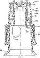
фиг.1 - частичный перспективный вид иллюстративной дозирующей укупорочной системы в форме отдельного дозирующего укупорочного средства, соответствующего предпочтительному варианту осуществления изобретения, причем укупорочное средство показано в закрытом положении на контейнере и в целом сверху или с верхней стороны укупорочного средства;FIG. 1 is a partial perspective view of an illustrative metering closure system in the form of a separate metering closure in accordance with a preferred embodiment of the invention, wherein the closure is shown in the closed position on the container and generally from above or from the top of the closure;
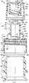
фиг.2 - перспективный вид с пространственным разделением деталей укупорочного средства, показанного на фиг.1;figure 2 is a perspective view with a spatial separation of the parts of the closure shown in figure 1;
фиг.3 - частичный вид сечения, выполненного в целом по линии 3-3 на фиг.1;figure 3 is a partial view of a section made generally along the line 3-3 in figure 1;
фиг.4 - вид, подобный показанному на фиг.3, но на фиг.4 показано укупорочное средство после приведения его в действие для приведения укупорочного средства в открытое положение;FIG. 4 is a view similar to that shown in FIG. 3, but FIG. 4 shows the closure after being actuated to bring the closure to the open position;
фиг.5 - вид, подобный показанному на фиг.4, но на фиг.5 показаны компоненты, отделенные друг от друга;5 is a view similar to that shown in figure 4, but figure 5 shows the components separated from each other;
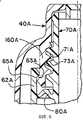
фиг.6 - частичный вид сечения, подобного показанному на фиг.3, но на фиг.6 показан второй вариант выполнения дозирующей укупорочной системы, соответствующей настоящему изобретению; иFIG. 6 is a partial sectional view similar to that shown in FIG. 3, but FIG. 6 shows a second embodiment of a metering closure system according to the present invention; and
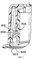
фиг.7 - частичный вид сечения, подобного показанному на фиг.3, но на фиг.7 показан третий вариант выполнения дозирующей укупорочной системы, соответствующей настоящему изобретению.FIG. 7 is a partial sectional view similar to that shown in FIG. 3, but FIG. 7 shows a third embodiment of a metering closure system according to the present invention.
Хотя настоящее изобретение допускает его осуществление во многих различных формах, это описание и прилагаемые чертежи показывают только некоторые конкретные формы в качестве примеров осуществления изобретения. Однако изобретение не ограничено описанными вариантами его осуществления. Объем изобретения определен прилагаемой формулой изобретения.Although the present invention allows for its implementation in many different forms, this description and the accompanying drawings show only some specific forms as examples of carrying out the invention. However, the invention is not limited to the described embodiments. The scope of the invention is defined by the attached claims.
Для облегчения описания большинство фигур, иллюстрирующих изобретение, показывают дозирующую укупорочную систему в типичной ориентации, которую она должна иметь на верхней части контейнера, когда контейнер стоит вертикально на его основании, и такие термины, как "верхний", "нижний", "горизонтальный" и т.д., использованы в отношении этого положения. Однако следует понимать, что дозирующую укупорочную систему, соответствующую изобретению, можно производить, хранить, транспортировать, использовать и продавать в ориентации, отличающейся от описанного положения.To facilitate the description, most of the figures illustrating the invention show a metering closure system in the typical orientation that it should have on the top of the container when the container is standing vertically on its base, and terms such as “top”, “bottom”, “horizontal” etc. are used in relation to this provision. However, it should be understood that the metering closure system according to the invention can be manufactured, stored, transported, used and sold in an orientation different from the described position.
Дозирующая укупорочная система, соответствующая настоящему изобретению, пригодна для использования с различными обычными или специальными контейнерами, имеющими разные конфигурации, детали которых, хотя они не показаны и не описаны, будут очевидны для специалистов в данной области техники и людей, представляющих себе такие контейнеры. Как таковой, описанный здесь контейнер не является частью настоящего изобретения и, таким образом, не ограничивает его. Специалистам в данной области техники также следует понимать, что новые не являющиеся очевидными отличительные аспекты изобретения воплощены только в описанных иллюстративных укупорочных системах.The dispensing closure system of the present invention is suitable for use with various conventional or special containers having different configurations, the details of which, although not shown and not described, will be apparent to those skilled in the art and to those who imagine such containers. As such, the container described herein is not part of the present invention and, therefore, does not limit it. Specialists in the art should also understand that the new non-obvious distinctive aspects of the invention are embodied only in the described illustrative closure systems.
Предпочтительный, в данном случае, вариант выполнения дозирующей конструкции или дозирующей укупорочной системы, соответствующей настоящему изобретению, показан на фиг.1-5 и обозначен на фиг.1 ссылочным номером 20. В показанном предпочтительном варианте осуществления изобретения дозирующая конструкция или дозирующая укупорочная система 20 выполнена в форме укупорочного средства 20, выполненного с возможностью установки на контейнер 22, который в обычном случае может содержать текучий материал. Контейнер 22 включает корпус 24 и горлышко 26, как показано на фиг.2. Горлышко 26 образует отверстие 28, сообщающееся с внутренним пространством контейнера. Горлышко 26 контейнера в предпочтительном варианте осуществления изобретения, показанном на фиг.2, имеет внешнюю охватываемую резьбу 58 для вхождения в зацепление с укупорочным средством 20.A preferred, in this case, embodiment of a metering structure or metering closure system according to the present invention is shown in FIGS. 1-5 and is indicated in FIG. 1 by
Корпус 24 контейнера 22 может иметь любую пригодную конфигурацию, и отступающее вверх горлышко 26 может иметь размер поперечного сечения и/или конфигурацию, отличные от размера и конфигурации корпуса 24 контейнера. В альтернативном варианте контейнер 22 может не иметь горлышка 26 как такового. Вместо этого контейнер 22 может состоять только из корпуса с отверстием. Контейнер 22 может иметь жесткую стенку или стенки, или он может иметь в некоторой степени гибкую стенку или стенки. Хотя контейнер, как таковой, может не составлять часть наиболее широких аспектов настоящего изобретения, следует понимать, что, по меньшей мере, корпус дозирующей конструкции или системы 20, соответствующей настоящему изобретению, может быть выполнен как единая с контейнером его верхняя часть или выступ. Однако в показанном предпочтительном варианте осуществления изобретения дозирующая система 20 является отдельным элементом (например, укупорочным средством), который приспособлен для установки, с возможностью отделения или без возможности отделения, на предварительно изготовленный контейнер 20, который имеет отверстие 28, сообщающееся с внутренним пространством контейнера.The
Укупорочное средство 20 приспособлено для использования с контейнером 22, имеющим отверстие 28 для обеспечения доступа к внутреннему пространству контейнера и к содержащемуся в нем продукту. Укупорочное средство 20 можно использовать с многими материалами, включая, но не ограничиваясь ими, жидкости относительно низкой или высокой вязкости, кремы, гели, суспензии, смеси, лосьоны, пасты, твердые частицы, гранулированные материалы и т.д., представляющие собой пищевые продукты, средства личной гигиены, промышленные или домашние моющие средства или другие относящиеся к делу составы (например, составы, используемые в ходе промышленного, коммерческого или домашнего ремонта, в строительстве, сельском хозяйстве и т.д.).The
Контейнер 22, с которым может использоваться укупорочное средство 20, в обычном случае может быть сжимаемым контейнером, имеющим гибкую стенку или стенки, которые пользователь может захватывать и сдавливать или сжимать для повышения внутреннего давления в контейнере таким образом, чтобы вытеснять продукт наружу из контейнера через укупорочное средство. Такая гибкая стенка контейнера в обычном случае имеет достаточную собственную упругость, чтобы при прекращении приложения сдавливающих сил стенка контейнера вновь приобретала ее нормальную, несжатую конфигурацию. Такой контейнер со сжимаемой стенкой предпочтителен во многих вариантах применения, но может не быть необходимым или предпочтительным в других вариантах применения. Например, в некоторых вариантах может быть желательно использовать в целом жесткий контейнер и повышать давление внутри контейнера в избранные моменты при помощи поршня или другой системы повышения давления.The
В данном случае предполагается, что во многих вариантах использования укупорочного средства 20 наиболее удобно выполнять некоторые или все компоненты укупорочного средства 20 посредством формования из пригодного термопластического и/или термореактивного материала или материалов. В показанном предпочтительном варианте осуществления изобретения каждый компонент укупорочного средства можно формовать из пригодного термопластического материала, такого как полипропилен. Компоненты укупорочного средства можно формовать отдельно из одного материала или из разных материалов. Материалы могут иметь одинаковые или разные цвета и структуры.In this case, it is assumed that in many applications of the
Как можно видеть на фиг.2, укупорочная система 20 включает два базовых компонента: (1) корпус 30 и (2) носик 40, который приспособлен для установки на корпус 30 и который может вращаться относительно корпуса 30.As can be seen in FIG. 2, the
Как можно видеть на фиг.5, корпус 30 укупорочного средства включает базовую часть или основание 50, которое содержит юбку 52 и проходящий внутрь в целом кольцевой уступ 54. На внутренней поверхности юбки 52 образована внутренняя резьба 56 для резьбового зацепления с внешней резьбой 58 на горлышке 26 контейнера.As can be seen in FIG. 5, the
В альтернативном варианте юбка 52 укупорочного средства может иметь вместо резьбы 56 какое-либо другое средство для соединения с контейнером, например выступ или канавку (не показаны) для зацепления с защелкиванием с канавкой или выступом (не показаны) соответственно горлышка контейнера. Корпус 30 укупорочного средства может быть также постоянно прикреплен к контейнеру 22 при помощи индукционной плавки, ультразвуковой плавки, склеивания и т.п., в зависимости от материалов, используемых для изготовления корпуса 30 укупорочного средства и контейнера 22. Корпус 30 укупорочного средства может быть также сформирован как единое целое с контейнером 22 или как выступ на нем.Alternatively, the
Юбка 52 корпуса укупорочного средства может иметь любую пригодную конфигурацию для приема отступающего вверх горлышка 26 или другой части контейнера 22, вставляемой в корпус 30 укупорочного средства определенной конфигурации, при этом основная часть контейнера 22 может иметь конфигурацию поперечного сечения, отличающуюся от конфигурации горлышка 26 контейнера и корпуса 30 укупорочного средства.The
При необходимости верхняя часть горлышка 26 контейнера или, в альтернативном варианте, нижняя сторона уступа 54 корпуса укупорочного средства может быть запечатана запечатывающим средством или прокладкой 60. Однако если указывающее на несанкционированное вскрытие запечатывающее средство или указывающее на нетронутость запечатывающее средство, образуемое такой прокладкой 60, не необходимо или не желательно в конкретном варианте осуществления изобретения, конечно прокладку 60 можно исключить.If necessary, the upper part of the neck of the
Кроме того, если необходимо, корпус 30 укупорочного средства может иметь кольцевое уплотнение (не показано), проходящее вниз от нижней стороны выступа 54 корпуса укупорочного средства. Таким уплотнением может быть уплотнение "клешневидного" профиля, пробочное уплотнение или любое другое такое уплотнение в зависимости от конкретного варианта применения и в зависимости от того, используется ли запечатывающее средство 60.Furthermore, if necessary, the
Как показано на фиг.5, основание 50 корпуса укупорочного средства включает кольцевую стенку 62 уменьшенного диаметра. На верхнем конце стенки 62 расположен отступающий наружу выступ 64. В альтернативном варианте осуществления изобретения, который не показан, применения стенки 62 уменьшенного диаметра не требуется. Основание 50 укупорочного средства вместо этого может включать продолжение верхней части юбки 52, которое может проходить вверх над резьбой 56 и иметь такой же диаметр, как и часть юбки 52, расположенная под резьбой 56. Более того, часть основания 50, расположенная над резьбой 56, может даже иметь больший диаметр, чем часть юбки 52 в районе резьбы 56 или под ней.As shown in FIG. 5, the
Как показано на фиг.5, корпус 30 укупорочного средства включает трубку или канал 70, соединенный с основанием 50 корпуса укупорочного средства при помощи промежуточной, в целом кольцевой гибкой стенки 80. Стенка 80 проходит вокруг периферии канала 70 таким образом, чтобы создавать полностью непроницаемый район между основанием 50 корпуса укупорочного средства и внешней поверхностью нижней части канала 70. Гибкая стенка 80 допускает вертикальное или возвратно-поступательное движение канала 70 относительно основания 50 корпуса укупорочного средства (и относительно контейнера 22, когда основание 50 корпуса укупорочного средства установлено на контейнер 22).As shown in FIG. 5, the
В показанной предпочтительной форме осуществления изобретения основание 50 корпуса укупорочного средства имеет в целом кольцевую конфигурацию, гибкая стенка 80 имеет в целом коническую или кольцевую конфигурацию, и канал 70 имеет в целом кольцевую конфигурацию. Однако эти детали или элементы корпуса 30 укупорочного средства могут иметь другие конфигурации. Например, основание 50 корпуса укупорочного средства могло бы иметь призматическую или многоугольную конфигурацию, приспособленную для установки на верхней части горлышка контейнера, имеющего многоугольную конфигурацию. Такие призматическая или многоугольная конфигурации не будут приспособлены для использования резьбового соединения, но может применяться другое средство для прикрепления, такое как защелкивающееся приспособление с выступом и канавкой и т.п.In the preferred embodiment shown, the
Канал 70 в показанном предпочтительном варианте осуществления изобретения выполнен с возможностью вращения носика 40, как подробно описано ниже. С этой целью в показанном предпочтительном варианте выполнения канала 70 канал 70 имеет в целом кольцевую конфигурацию, допускающую вращение на нем носика 40. Однако в альтернативных вариантах осуществления изобретения (не показаны) существенная часть канала 70 может не быть кольцевой и вместо этого может иметь другие конфигурации, например многоугольные или призматические конфигурации, если, по меньшей мере, часть канала 70 может взаимодействовать с носиком 40 как часть приводной системы преобразования вращательного движения в линейное, одна форма которой описана ниже подробно.
Канал 70 образует внутренний выпускной проход 84, который открыт снизу во внутренний район, образованный полым основанием 50 корпуса укупорочного средства. Совместно полое основание 50 корпуса и канал 70 могут быть охарактеризованы как образующие выпускной проход протяженностью от одного конца корпуса 30 укупорочного средства до другого конца корпуса 30 укупорочного средства. Когда корпус 30 укупорочного средства установлен на горлышко 26 контейнера (фиг.4), выпускной проход можно рассматривать как проходящий, по меньшей мере, от верхнего конца или отверстия горлышка 26 контейнера, через корпус 30 укупорочного средства, к верхнему концу корпуса 30 укупорочного средства.
Верхний конец корпуса 30 укупорочного средства образован верхним концом канала 70, который имеет выпускное отверстие или отверстия 90 (фиг.2). Как можно видеть на фиг.2, в предпочтительном варианте осуществления изобретения применяют три дугообразных выпускных отверстия 90, которые образованы между тремя проходящими внутрь опорными стенками или ребрами 94 (два из ребер 94 можно видеть на фиг.2). Проходящие внутрь ребра 94 удерживают центральную пробку 100, как показано на фиг.2 и 5. Пробка 100 канала включает в целом цилиндрическую внешнюю первую уплотнительную поверхность 116, которую можно видеть на фиг.2 и 5.The upper end of the
Вокруг отверстий 90 и ребер 94 проходит радиально наружу кольцевой выступ 101, образующий скользящее уплотнение (фиг.2) для вхождения в уплотняющий контакт с носиком 40, как подробно описано ниже.Around the
Нижний конец канала 70 в предпочтительном варианте осуществления изобретения, показанном на фиг.5, имеет острую нижнюю кромку с частью окружности, проходящей вниз, на некоторое расстояние дальше остальной части окружности нижнего конца для образования точки или прокалывающего района 110.The lower end of the
Носик 40 включает юбку 120 и кольцевую верхнюю площадку 122, которая ограничивает дозирующее отверстие 42 (фиг.5). От нижней стороны верхней площадки 122 проходит вниз кольцевой выступ 124. Внутренняя поверхность кольцевого выступа 124 немного скошена наружу для образования конической поверхности 126, которую можно видеть на фиг.5. От конической поверхности 126 проходит наверх кольцевая стенка, которая образует по существу цилиндрическую вторую внутреннюю поверхность дозирующего отверстия 42. Вторая поверхность 130 носика выполнена с возможностью вхождения в непроницаемый контакт с первой уплотнительной поверхностью 116 пробки канала, как показано на фиг.3.
Как показано на фиг.5, юбка 120 носика включает расположенный на ее нижнем конце отступающий радиально внутрь защелкивающийся выступ 140. Как показано на фиг.3, защелкивающийся выступ 140 юбки носика выполнен с возможностью для защелкивания под отступающим радиально наружу выступом 64 корпуса укупорочного средства и вхождения в зацепление с ним. Юбка 120 носика имеет достаточную гибкость и упругость для временного расширения по окружности и отклонения юбки 120 на величину, достаточную для обеспечения прохождения выступа 140 юбки поверх выступа 64 корпуса укупорочного средства и защелкивания под ним. Для облегчения этого процесса установки и введения в зацепление верхняя часть выступа 64 корпуса укупорочного средства скошена или имеет конусообразную конфигурацию, и выступ 140 юбки носика имеет подобным образом ориентированный скос или конусообразную конфигурацию.As shown in FIG. 5, the
Корпус 30 укупорочного средства и носик 40 совместно образуют приводную систему преобразования вращательного движения в линейное движение, которая в предпочтительном варианте осуществления изобретения, показанном на фиг.1-5, включает четыре, по существу, спиральные кулачковые канавки или направляющие 150 (фиг.5), образованные на внутренней поверхности стенки 160, отступающей вниз от нижней стороны площадки 122 носика, и четыре кулачка или кулачковых следящих элемента 170 (фиг.5), отступающих радиально наружу от внешней поверхности канала 70. Каждый кулачок 170 приспособлен для приема в одну из четырех кулачковых направляющих 150.The
Как показано на фиг.3, носик 40 может быть первоначально навинчен на кулачки 170, пока защелкивающийся выступ 140 юбки носика не защелкнется под выступом 64 корпуса укупорочного средства, и дозирующее отверстие носика не будет закупорено пробкой 100 канала таким образом, чтобы первая уплотнительная поверхность 116 канала входила в непроницаемый контакт со второй уплотнительной поверхностью 130 носика (фиг.3).As shown in FIG. 3, the
Когда необходимо открыть контейнер 22, носик 40 можно вращать в одном направлении (против часовой стрелки при взгляде на фиг.1). Поскольку носик 40 зафиксирован по высоте на корпусе 30 укупорочного средства благодаря вхождению в зацепление выступа 64 корпуса 30 укупорочного средства и выступа 140 юбки носика, носик 40 просто вращается без совершения какого-либо перемещения или движения в осевом направлении. Вращающий момент при вращении носика передается каналу 70 как осевое усилие кулачковыми направляющими 150, входящими в зацепление с кулачками 170 канала, и это вызывает движение канала 70 вниз из поднятого закрытого положения, показанного на фиг.3, в опущенное открытое положение, показанное на фиг.4. Когда канал 70 движется вниз, кольцевая гибкая стенка 80 деформируется или отклоняется, как необходимо, для обеспечения движения вниз, и прокалывающая часть 110 канала 70 прокалывает прокладку 60 (если вспомогательную прокладку 60 используют в упаковке). Движение канала 70 вниз обеспечивает вырезание в прокладке 60 клапана 190 и отгибание его вниз таким образом, что клапан свисает в целом вертикально вниз на небольшой оставшейся неповрежденной части, отнесенной приблизительно на 180° от точки 110 нижней кромки канала.When it is necessary to open the
Движение канала 70 вниз прекращается, когда гибкая стенка 80 достигает предела ее деформации вниз, как показано на фиг.4. Попытка пользователя продолжать вращать носик 40 в направлении открывания (против часовой стрелки при взгляде на фиг.1) для дальнейшего перемещения канала 70 вниз сталкивается с сопротивлением или ограничением, сообщаемым каналу 70 деформированной гибкой стенкой 80, и пользователь обнаруживает, что продолжать вращение носика 40 в направлении открывания невозможно. Это дает пользователю ощущаемое указание на то, что прокладка 60 надлежащим образом проколота и/или что укупорочное средство 20 находится в полностью открытом состоянии, как показано на фиг.4.The downward movement of the
Когда укупорочное средство 20 находится в полностью открытом положении, показанном на фиг.4, пользователь может наклонить или перевернуть упаковку для облегчения выдачи текучего продукта под воздействием силы тяжести. Если контейнер 22 имеет гибкую стенку или стенки, контейнер 22 можно сжать для дополнительного содействия выдаче продукта.When the
После выдачи необходимого количества продукта упаковку можно опять установить в вертикальное положение, и пользователь может повернуть носик 40 по часовой стрелке (при взгляде на фиг.1) для перемещения канала 70 вверх в полностью закрытое положение, показанное на фиг.3.After dispensing the required amount of product, the packaging can again be placed in a vertical position, and the user can turn the
Когда укупорочное средство 20 находится в полностью закрытом положении, показанном на фиг.3, гибкая стенка 80 оказывается перемещенной в отклоненное вверх положение, и дальнейшее движение вверх канала 70 предотвращается кулачками 170, упирающимися в верхние концы принимающих кулачки канавок 150. Таким образом, пользователь не может продолжать вращение носика 40 по часовой стрелке.When the
Как показано на фиг.3 и 4, носик 40 всегда сохраняет свое положение в осевом направлении или по высоте относительно корпуса 30 укупорочного средства. Кроме того, юбка 52 корпуса укупорочного средства всегда остается в одном зафиксированном положении по высоте относительно контейнера 22 и относительно носика 40. Работа укупорочного средства 20 посредством вращения носика 40 для открывания или закрывания укупорочного устройства не создает каких-либо щелей.As shown in FIGS. 3 and 4, the
Внутренняя поверхность внутренней стенки 160 носика над спиральными кулачковыми канавками 150 входит в уплотнительный контакт с уплотнительным выступом 101 верхнего конца корпуса укупорочного средства, как показано на фиг.3. Это обеспечивает получение непрерывно уплотненного дозирующего прохода, образованного внутренней поверхностью стенки 160 носика и каналом 70 при открывании (и закрывании) системы, когда канал 70 движется вверх и вниз.The inner surface of the
Будет понятно, что прокладку 60 можно не применять. Если прокладку 60 не применяют, канал 70 может не иметь острой режущей нижней кромки и может заканчиваться (то есть не проходить ниже) в районе гибкой стенки 80.It will be understood that the
В альтернативном варианте осуществления изобретения, показанном на фиг.6, носик 40А укупорочного средства защелкивается внутри выступающей вверх кольцевой стенки 62А корпуса укупорочного средства. С этой целью стенка 62А корпуса укупорочного средства имеет отступающий радиально внутрь кольцевой выступ 63А, и носик 40А имеет проходящее вниз кольцо 160А с отступающим радиально наружу кольцевым выступом 65А, входящим в зацепление с выступом 63А посредством защелкивания.In the alternative embodiment of FIG. 6, the
Канал 70А соединен со стенкой 62А корпуса укупорочного средства гибкой стенкой 80А. Кроме того, внешняя поверхность канала 70А включает резьбу 71А для вхождения в зацепление с резьбой 73А на внутренней стороне стенки 160А носика. Резьбовое соединение между резьбами 71А и 73А функционально заменяет вхождение в зацепление кулачковой направляющей и кулачкового следящего элемента, описанных выше со ссылками на первый вариант осуществления изобретения, показанный на фиг.1-5. Другие аспекты второго варианта осуществления изобретения, показанного на фиг.6, могут быть по существу аналогичными или подобными соответствующим отличительным признакам первого варианта осуществления изобретения, показанным на фиг.1-5.The
На фиг.7 показан третий вариант выполнения укупорочной системы, в котором носик 40В окружает приводимый кулачком канал 70В, который соединен со стенкой 62В корпуса укупорочного средства гибкой стенкой 80В. Гибкая стенка 80В включает утолщенные кольца 81В и канавки или тонкие перемычки 83В. Конфигурация стенки 80В может обеспечивать улучшенную гибкость при перемещении, одновременно поддерживая устойчивость при вращении носика 40В для открывания или закрывания системы. Другие отличительные признаки третьего варианта выполнения укупорочного средства по существу аналогичны соответствующим отличительным признакам первого варианта осуществления изобретения, описанного выше со ссылками на фиг.1-5.7 shows a third embodiment of a closure system in which the spout 40B surrounds a cam-driven
Также будет понятно, что дозирующая укупорочная система 20, соответствующая изобретению, может быть легко приспособлена для включения в нее указывающих на несанкционированное вскрытие признаков и/или признаков защиты от открывания детьми. Такие отличительные признаки могут быть включены в конструкцию корпуса укупорочного средства и/или могут включать внешние крышки или термоусадочные пленки (не показаны). Например, будет понятно, что, если необходимо, можно использовать индицирующую несанкционированное вскрытие ленту (не показана) между корпусом 30 укупорочного средства и контейнером 22. Такая индицирующая несанкционированное вскрытие лента может удерживаться слабыми соединениями на нижней кромке юбки корпуса укупорочного средства и может иметь отогнутую нижнюю кромку для вхождения в контакт с нижней стороной фланца на контейнере.It will also be understood that the
Корпус 30 укупорочного средства можно также прикреплять к контейнеру без возможности отсоединения независимо от того, применяют ли индицирующую несанкционированное вскрытие ленту.The
Кроме того, если необходимо, на корпусе 30 укупорочного средства можно устанавливать внешнюю крышку (не показана) для закрывания и защиты носика 40 укупорочного средства. Такая внешняя крышка может быть полностью отдельным компонентом, или такая внешняя крышка может быть связана с корпусом 30 укупорочного средства пригодным шарниром или полоской.In addition, if necessary, an outer cover (not shown) can be installed on the
Корпус укупорочного средства, такой как корпус 30, показанный на фиг.5, можно формовать посредством литья под давлением двух материалов, чтобы для получения гибкой стенки 80 можно было использовать более гибкий материал по сравнению с менее гибким материалом, используемым для получения остальной части корпуса 30 укупорочного средства.The closure body, such as the
Также следует понимать, что дозирующая система, соответствующая настоящему изобретению, может не быть отдельным укупорочным средством для контейнера. Вместо этого корпус 30 укупорочного средства можно формовать как часть, составляющую единое целое с контейнером 22. Контейнер можно формовать таким образом, чтобы он имел (1) первоначально открытый нижний конец, (2) периферийную стенку, формирующую верхний конец, образующий отверстие в верхнем конце контейнера, и (3) составляющий единое целое с контейнером корпус укупорочного средства, проходящий радиально внутрь от периферийной стенки контейнера над отверстием в верхнем конце контейнера таким образом, чтобы формировать единую с верхним концом контейнера часть и формировать стенку 62 корпуса укупорочного средства на верхнем конце, гибкую стенку 80 и канал 70. Затем может быть установлен носик 40 для закрывания укупорочного средства. Затем контейнер можно заполнить продуктом через открытый нижний конец, и открытый нижний конец можно затем герметично закрыть с использованием температурной деформации или при помощи отдельной донной заглушки или крышки.It should also be understood that the dispensing system of the present invention may not be a separate container closure. Instead, the
При ознакомлении с вышеизложенным подробным описанием вариантов осуществления изобретения и их иллюстрациями будет легко понять, что в них можно внести многие изменения и модификации без отхода от сущности и объема замысла или принципов настоящего изобретения.When reviewing the above detailed description of embodiments of the invention and their illustrations, it will be easy to understand that many changes and modifications can be made to them without departing from the essence and scope of the concept or principles of the present invention.
Claims (13)
Translated fromRussianApplications Claiming Priority (2)
| Application Number | Priority Date | Filing Date | Title |
|---|---|---|---|
| US09/929,389 | 2001-08-14 | ||
| US09/929,389US6477743B1 (en) | 2001-08-14 | 2001-08-14 | Twist-openable dispensing closure accommodating optional liner puncture feature |
Publications (2)
| Publication Number | Publication Date |
|---|---|
| RU2004107506A RU2004107506A (en) | 2004-12-27 |
| RU2290356C2true RU2290356C2 (en) | 2006-12-27 |
Family
ID=25457784
Family Applications (1)
| Application Number | Title | Priority Date | Filing Date |
|---|---|---|---|
| RU2004107506/12ARU2290356C2 (en) | 2001-08-14 | 2002-07-12 | Metering sealing device opened by rotation and containing auxiliary gasket piercing member |
Country Status (12)
| Country | Link |
|---|---|
| US (1) | US6477743B1 (en) |
| EP (1) | EP1427643A4 (en) |
| JP (1) | JP2005500207A (en) |
| CN (1) | CN1269691C (en) |
| AR (1) | AR034956A1 (en) |
| AU (1) | AU2002320484B2 (en) |
| BR (1) | BR0211881A (en) |
| CA (1) | CA2457752A1 (en) |
| MX (1) | MXPA04001097A (en) |
| PL (1) | PL200210B1 (en) |
| RU (1) | RU2290356C2 (en) |
| WO (1) | WO2003016157A1 (en) |
Families Citing this family (103)
| Publication number | Priority date | Publication date | Assignee | Title |
|---|---|---|---|---|
| US9452870B1 (en) | 1987-01-20 | 2016-09-27 | Michael Anderson | Two-piece double-sealed dispensing capsule with button blast and drink through feature |
| USD530610S1 (en) | 1997-10-28 | 2006-10-24 | Gateway Plastic, Inc. | Integrally-formed closure for a container |
| US6460718B1 (en)* | 1997-10-28 | 2002-10-08 | Gateway Plastics Incorporated | Container with a threaded cap having a stepped sealing ring with a plurality of narrow sealing surfaces |
| US7942284B2 (en)* | 2000-03-27 | 2011-05-17 | Minimizim, L.L.C. | Apparatus for removing tamper-evident seals from containers |
| US6959841B2 (en)* | 2000-11-01 | 2005-11-01 | Vlodek James A | Closure with selectively operable dispense feature |
| AU2002257483B2 (en)* | 2001-06-27 | 2006-11-30 | Bericap Holding Gmbh | Closing device with a piercing element |
| US6702161B2 (en) | 2001-12-12 | 2004-03-09 | Portola Packaging, Inc. | Closure having rotatable spout and axially movable stem |
| US6571994B1 (en) | 2001-12-12 | 2003-06-03 | Portola Packaging, Inc. | Closure having rotatable spout and axially movable stem |
| US7261226B2 (en)* | 2001-12-12 | 2007-08-28 | Portola Packaging, Inc. | Closure having rotatable spout and axially movable stem |
| US6691901B2 (en) | 2001-12-14 | 2004-02-17 | Gateway Plastics, Inc. | Closure for a container |
| AU2002359098A1 (en)* | 2001-12-18 | 2003-06-30 | Alto Packaging Limited | Sipper cap with reciprocally movable nozzle |
| CN100345729C (en)* | 2002-06-20 | 2007-10-31 | Sig技术有限公司 | Self-opening closures for composite packaging or for spouts of containers or bottles sealed with film material |
| CA2492900A1 (en)* | 2002-07-22 | 2004-01-29 | Courtesy Corporation | Beverage closure with open/close spout |
| USD513452S1 (en) | 2002-09-27 | 2006-01-10 | Gateway Plastics, Inc. | Closure for a container |
| DE10254409A1 (en)* | 2002-11-21 | 2004-06-03 | Ernst Mühlbauer Gmbh & Co. Kg | Device for mixing and dispensing multicomponent masses |
| EP1590249A2 (en)* | 2002-12-04 | 2005-11-02 | Graham Packaging Company, L.P. | One piece push-pull cap for plastic containers |
| NZ523373A (en)* | 2002-12-20 | 2005-08-26 | Alto Plastics Ltd | Tamper evident closure assemblies |
| WO2004080825A2 (en)* | 2003-03-11 | 2004-09-23 | Graham Packaging Company L.P. | Resealable closure system |
| GB0306767D0 (en)* | 2003-03-25 | 2003-04-30 | Syltone Plc | Valves |
| US7172095B2 (en)* | 2003-04-18 | 2007-02-06 | Christopher John Marshall | Bottle closure containing beverage concentrate |
| WO2005009859A1 (en)* | 2003-07-28 | 2005-02-03 | Sig Technology Ltd. | Drinking and pouring closure with a piercing cutter device for composite packagings or container and bottle spouts sealed with a film material |
| EP1682443B1 (en) | 2003-10-27 | 2010-05-19 | Portola Packaging, Inc. | Twist-open closure having inclined frangible membrane |
| US20050184076A1 (en)* | 2004-02-19 | 2005-08-25 | Chang Ping F. | Bottle cap assembly |
| USD507744S1 (en)* | 2004-03-22 | 2005-07-26 | Crown Packaging Technology, Inc. | Dispensing closure |
| CN100363240C (en)* | 2004-04-23 | 2008-01-23 | 赵明 | Helical embedded linkage opened bottle cap capable of throttling drink flow |
| US20050247714A1 (en)* | 2004-05-05 | 2005-11-10 | Backes Cory R | Closure for drink bottle |
| US8066158B2 (en) | 2004-09-05 | 2011-11-29 | Gateway Plastics, Inc. | Closure for a container |
| USD533452S1 (en) | 2004-11-20 | 2006-12-12 | Gateway Plastics, Inc. | Closure for a container |
| USD532691S1 (en) | 2004-11-20 | 2006-11-28 | Gateway Plastics, Inc. | Closure for a container |
| USD532298S1 (en) | 2004-11-20 | 2006-11-21 | Gateway Plastics, Inc. | Closure for a container |
| KR100597217B1 (en)* | 2004-11-23 | 2006-07-06 | 조영국 | Anti-counterfeiting double cap with additives |
| JP4756496B2 (en)* | 2004-12-22 | 2011-08-24 | ザ プロクター アンド ギャンブル カンパニー | Pumping container with pump |
| WO2007014048A1 (en)* | 2005-07-21 | 2007-02-01 | Plastek Industries, Inc. | Condiment dispenser |
| US20070076064A1 (en)* | 2005-09-30 | 2007-04-05 | Yong Wang | Cap assembly for an ink bottle |
| ATE490929T1 (en)* | 2005-10-06 | 2010-12-15 | Capartis Ag | CONTAINER CLOSURE |
| JP2009509885A (en)* | 2005-10-07 | 2009-03-12 | アマン,レイナー | Closing device |
| CH698661B1 (en)* | 2006-01-29 | 2009-09-30 | Belcap Switzerland Ag | Closing device with partially circular cutting ring. |
| EP1816084B1 (en)* | 2006-02-06 | 2009-09-23 | The Procter and Gamble Company | Dispensing closure for containers |
| US20070199953A1 (en)* | 2006-02-27 | 2007-08-30 | Laveault Richard A | Dispensing container for two flowable products |
| US7607555B2 (en)* | 2006-03-01 | 2009-10-27 | Ds Smith Plastics Limited | Puncturable cap and piercer |
| US8109396B1 (en) | 2006-03-31 | 2012-02-07 | Rexam Healthcare Packaging Inc. | Slide rails and friction surfaces for closure |
| US7815061B1 (en) | 2006-03-31 | 2010-10-19 | Rexam Closures And Containers | Friction surface for push and turn child resistant closure |
| USD596029S1 (en) | 2006-06-20 | 2009-07-14 | Gateway Plastics, Inc. | Closure for a container |
| USD551564S1 (en) | 2006-06-23 | 2007-09-25 | Sabritas, S. De R.I. De C.V. | Food container |
| US8702751B2 (en)* | 2006-06-30 | 2014-04-22 | Advanced Medical Solutions (Plymouth) Limited | Surgical adhesive applicator |
| US8518076B2 (en)* | 2007-01-08 | 2013-08-27 | Advanced Medical Solutions (Plymouth) Limited | Surgical adhesive applicator |
| JP5021323B2 (en)* | 2007-01-25 | 2012-09-05 | 東洋製罐株式会社 | Inspection container |
| USD603274S1 (en) | 2007-01-31 | 2009-11-03 | Sabritas, S. De R.L. De C.V. | Food container |
| US7717304B2 (en)* | 2007-01-31 | 2010-05-18 | Sabritas, S. De R.L. De C.V. | Method and apparatus for dispensing for paste-like substances |
| EP2132132A4 (en)* | 2007-03-02 | 2013-02-20 | Ds Smith Plastics Ltd | CLOSURE FOR CHILDREN-RESISTANT FAUCETS |
| WO2008144714A1 (en)* | 2007-05-21 | 2008-11-27 | Plastek Industries, Inc. | Closure valve |
| AU2008203457B2 (en)* | 2007-08-01 | 2011-05-26 | Entapack Pty Ltd | Opening mechanism for a flexible container |
| US8070014B2 (en)* | 2007-08-24 | 2011-12-06 | Seaquist Closures L.L.C. | Liner piercing twist closure |
| US20090194533A1 (en)* | 2008-02-04 | 2009-08-06 | Lizerbram Eric K | Closure with additive reservoir |
| DE202008003937U1 (en) | 2008-03-20 | 2008-06-12 | Mauer Ag | Dosing closure for tubes |
| NL2001533C2 (en)* | 2008-04-28 | 2009-10-30 | Helvoet Rubber & Plastic Techn | Nozzle connector for coupling nozzle to fluid container e.g. plastic bottle, has tube part coupled with piercing element, where piercing element is axially movable relative to tube part |
| US8342765B2 (en) | 2008-06-12 | 2013-01-01 | Advanced Medical Solutions (Plymouth) Limited | Liquid applicator |
| US20100108724A1 (en)* | 2008-10-30 | 2010-05-06 | Gilbert Buchalter | Twist open/twist close Closure |
| CN101734417B (en)* | 2008-11-13 | 2012-12-26 | 西奎斯特盖有限责任合作公司 | Bendable sealing element capable of penetrating through liner plate |
| US20100186848A1 (en)* | 2008-12-04 | 2010-07-29 | Moorad Thomas S | Dispenser and method |
| US8701906B1 (en) | 2008-12-31 | 2014-04-22 | Blast Max Llc | Ingredient dispensing cap for mixing beverages with push-pull drinking spout |
| US8544685B2 (en)* | 2009-09-08 | 2013-10-01 | Calibre Closures Llc | Reclosable dispensing closure |
| KR101674704B1 (en)* | 2009-11-25 | 2016-11-09 | 백스터 인터내셔널 인코포레이티드 | Drip chamber with flow control |
| US9936834B2 (en) | 2010-02-01 | 2018-04-10 | Bedford Systems Llc | Method and apparatus for cartridge-based carbonation of beverages |
| CN102843938B (en) | 2010-02-01 | 2016-01-20 | 库里格绿山股份有限公司 | Method and apparatus for cartridge-based carbonation of beverages |
| KR101023264B1 (en)* | 2010-06-11 | 2011-03-21 | 한정식 | pack |
| US8459502B2 (en) | 2010-09-03 | 2013-06-11 | Calibre Closures, LLC | Reclosable dispensing closure with vent |
| JP5932821B2 (en) | 2011-01-14 | 2016-06-08 | ザ プロクター アンド ギャンブル カンパニー | Container and method for manufacturing the container |
| CN103201185B (en) | 2011-01-14 | 2016-06-08 | 宝洁公司 | Closure member for container |
| US8479914B2 (en) | 2011-05-13 | 2013-07-09 | Lidquids, Llc | System and method for dispensing additives to a container |
| US8678183B2 (en) | 2011-05-13 | 2014-03-25 | Lidquids, Llc | System and method for dispensing additives to a container |
| US9567142B1 (en) | 2011-05-27 | 2017-02-14 | Michael Anderson | One-piece dispensing capsule with integral plunger |
| US8646659B2 (en) | 2011-08-24 | 2014-02-11 | Calibre Closures Llc | Dispensing container for dispensing predetermined amounts of product |
| CN102616453B (en)* | 2011-12-31 | 2014-04-16 | 深圳市通产丽星股份有限公司 | Antitheft packaging container |
| US20130221032A1 (en)* | 2012-02-24 | 2013-08-29 | The Coca-Cola Company | Mechanical Dispensing System |
| USD704554S1 (en)* | 2012-06-04 | 2014-05-13 | Halcyon International, LLC. | Lugged cap assembly |
| CN104755384A (en) | 2012-10-30 | 2015-07-01 | 宝洁公司 | A closure for a container |
| FR3000036B1 (en)* | 2012-12-26 | 2015-02-20 | Albea Services | TUBE HEAD PROVIDED WITH AN OPERATOR ASSOCIATED WITH AN IMPROVED PERFORATOR PLUG ENSURING THE PRESERVATION OF THE OPERATOR PRIOR TO ITS FIRST USE |
| US20140209490A1 (en) | 2013-01-28 | 2014-07-31 | Mass Probiotics, Inc. | Cap and ingredient for multi-compartment container |
| JP5961568B2 (en)* | 2013-02-14 | 2016-08-02 | 株式会社吉野工業所 | Liquid discharge container |
| US9186689B2 (en)* | 2013-10-22 | 2015-11-17 | Yonwoo Co., Ltd. | Cap-integrated pumping type cosmetic container |
| CN103723349B (en)* | 2013-12-27 | 2016-03-30 | 宁波瑞成包装材料有限公司 | A kind of wine bag |
| FR3020051B1 (en)* | 2014-04-16 | 2016-05-13 | Aptar France Sas | FLUID PRODUCT DISPENSER. |
| ES2638854T3 (en)* | 2014-04-16 | 2017-10-24 | Sanhua Aweco Appliance Systems Gmbh | Drying device for domestic machines |
| CN103950630A (en)* | 2014-05-19 | 2014-07-30 | 南京小洋人生物科技发展有限公司 | Bottle cap with sanitary opening device |
| CH709847A2 (en)* | 2014-07-03 | 2016-01-15 | Capartis Ag | Pour closure for the neck of a container, in particular a canister for controlled multi-pouring. |
| BR112017014444A2 (en) | 2015-03-05 | 2018-01-16 | Aptargroup Inc | snap-in assembly and overcap for same |
| US10301057B2 (en) | 2016-07-11 | 2019-05-28 | Calibre Closures Llc | Dispensing container with internal squeeze limiting member |
| CN109689530B (en)* | 2016-09-20 | 2021-09-14 | 雀巢产品有限公司 | Container end cap assembly |
| JP6357605B1 (en)* | 2016-12-09 | 2018-07-11 | 東罐興業株式会社 | Cap for container |
| CN109963792B (en)* | 2016-12-29 | 2021-07-27 | 伯拉考成像股份公司 | Rotary operated container closure |
| CN107175046A (en)* | 2017-07-04 | 2017-09-19 | 安徽恒创环保建材有限公司 | Autoclave |
| CN107963326A (en)* | 2017-11-22 | 2018-04-27 | 深圳市通产丽星股份有限公司 | A kind of rotary sealing type packing container |
| CN120621888A (en)* | 2018-03-01 | 2025-09-12 | 安德烈·卢洽娜·马丁斯 | Automatic opening device for containers with sealing elements |
| US10414645B1 (en)* | 2019-02-05 | 2019-09-17 | Rodney Laible | Container insert for use in a closed loop dispensing system |
| CN114275333B (en)* | 2020-07-02 | 2025-01-24 | 中山市华宝勒生活用品有限公司 | Rotating closure cover |
| CN116761761A (en)* | 2020-10-30 | 2023-09-15 | C环包装瑞典股份公司 | Pattern can end modular dispensing system with enhanced recyclability |
| US20240025603A1 (en)* | 2020-10-30 | 2024-01-25 | C-Loop Packaging Sweden Ab | Patterned can end modular dispensing systems with enhanced recyclability |
| JP2023552064A (en)* | 2020-10-30 | 2023-12-14 | シー ― ループ パッケージング スウェーデン アクチエボラグ | Patterned can end modular distribution system for increased recyclability |
| CN113401495A (en)* | 2021-07-23 | 2021-09-17 | 赵梦兰 | Automatic opening packaging cover |
| DE102021121117B3 (en) | 2021-08-13 | 2022-04-14 | Andreas Schmidt | LIQUID CAP WITH DOSING |
| CN116280680A (en)* | 2023-04-17 | 2023-06-23 | 大兴安岭至臻尚品寒带生物技术有限公司 | Storage screwing type AQD solid-liquid separation bottle cap |
| USD1068472S1 (en) | 2023-05-01 | 2025-04-01 | C-Loop Packaging Sweden Ab | Can end |
Citations (4)
| Publication number | Priority date | Publication date | Assignee | Title |
|---|---|---|---|---|
| US5456374A (en)* | 1994-09-19 | 1995-10-10 | Beck; Matthew R. | Tamper evident container closure |
| RU2067959C1 (en)* | 1993-06-02 | 1996-10-20 | Юрий Васильевич Пименов | Packing |
| US5810185A (en)* | 1995-03-02 | 1998-09-22 | Groesbeck; Robert Clay | Reclosable bottle closure for carbonated beverages and the like |
| US5853109A (en)* | 1998-04-29 | 1998-12-29 | Aptargroup, Inc. | Dispensing structure with displaceable penetrator and bistable cover actuator |
Family Cites Families (24)
| Publication number | Priority date | Publication date | Assignee | Title |
|---|---|---|---|---|
| US2998170A (en)* | 1957-10-25 | 1961-08-29 | Manzione Homero Luis | Cap for paste tubes |
| FR1479110A (en) | 1966-05-10 | 1967-04-28 | Perforating cap with flexible or deformable membrane | |
| US3580423A (en) | 1969-02-27 | 1971-05-25 | Realistic Co | Container closure and apparatus for opening same |
| US4234103A (en) | 1978-03-31 | 1980-11-18 | Baxter Travenol Laboratories, Inc. | Diagnostic reagent dispensing bottle |
| US4234104A (en) | 1978-06-02 | 1980-11-18 | Apuzzo Jr Louis J | Toothpaste dispenser having a slip clutch drive mechanism |
| US4307821A (en) | 1980-08-22 | 1981-12-29 | Mack-Wayne Plastics Company | Container-closure assembly |
| CH672626A5 (en) | 1987-06-16 | 1989-12-15 | Alfatechnic Ag | |
| BE1000760A6 (en)* | 1987-07-27 | 1989-03-28 | Lynes Holding Sa | POURING CAP DEVICE. |
| US4771919A (en)* | 1987-10-28 | 1988-09-20 | Illinois Tool Works Inc. | Dispensing device for multiple components |
| FR2647089B1 (en) | 1989-05-17 | 1991-11-15 | Rical Sa | POURER FOR LIKE BOTTLES AND CONTAINERS, WITH A DRILLING ELEMENT FOR PUNCHING A LID OF THE CONTAINER |
| US5139182A (en) | 1989-08-16 | 1992-08-18 | Constandinos Appla | Closure and dispensing device for containers |
| US5566859A (en) | 1991-09-19 | 1996-10-22 | Willis; Charles M. | Foil piercing and clearing nozzle |
| DE9204076U1 (en)* | 1992-03-25 | 1993-07-22 | Schuckmann, Alfred Von, 4178 Kevelaer | Closure for tubes or similar |
| US5482176A (en) | 1994-03-16 | 1996-01-09 | The West Company, Incorporated | Membrane piercing closure and spout assembly |
| US5431305A (en) | 1994-04-15 | 1995-07-11 | Owens-Illinois Plastic Products Inc. | Tamper evident liquid dispensing package |
| US5680969A (en) | 1995-12-18 | 1997-10-28 | Aptargroup, Inc. | Closure with dispensing valve and separate releasable internal shipping seal |
| US5692651A (en) | 1996-06-06 | 1997-12-02 | Owens-Illinois Closure Inc. | Self-sealing dispensing closure |
| US5992668A (en) | 1996-07-11 | 1999-11-30 | Aptargroup, Inc. | Sealed dispensing closure with a sealed penetrator |
| US6045004A (en) | 1998-03-20 | 2000-04-04 | Aptargroup, Inc. | Dispensing structure with dispensing valve and barrier penetrator |
| US5938086A (en) | 1998-11-05 | 1999-08-17 | Aptargroup, Inc. | Container and closure with non-rising rotatable housing, dispensing valve, and separate releasable internal shipping seal |
| US6039198A (en) | 1998-11-24 | 2000-03-21 | Owens-Illinois Closure Inc. | Pierce and cut closure |
| FR2787423B1 (en)* | 1998-12-21 | 2001-02-23 | Qualipac Sa | CLOSING DEVICE FOR FLEXIBLE CONTAINER |
| GB9916693D0 (en) | 1999-07-16 | 1999-09-15 | Crown Cork & Seal Tech Corp | Dispensing closures |
| US6357634B1 (en)* | 1999-10-12 | 2002-03-19 | Sussex Technology Inc. | Container cap dispensing apparatus |
- 2001
- 2001-08-14USUS09/929,389patent/US6477743B1/ennot_activeExpired - Fee Related
- 2002
- 2002-07-12BRBR0211881-5Apatent/BR0211881A/enactiveSearch and Examination
- 2002-07-12PLPL367788Apatent/PL200210B1/ennot_activeIP Right Cessation
- 2002-07-12EPEP02750002Apatent/EP1427643A4/ennot_activeWithdrawn
- 2002-07-12JPJP2003521098Apatent/JP2005500207A/enactivePending
- 2002-07-12MXMXPA04001097Apatent/MXPA04001097A/enactiveIP Right Grant
- 2002-07-12AUAU2002320484Apatent/AU2002320484B2/ennot_activeCeased
- 2002-07-12CACA002457752Apatent/CA2457752A1/ennot_activeAbandoned
- 2002-07-12WOPCT/US2002/022226patent/WO2003016157A1/enactiveApplication Filing
- 2002-07-12CNCN02815886.5Apatent/CN1269691C/ennot_activeExpired - Fee Related
- 2002-07-12RURU2004107506/12Apatent/RU2290356C2/ennot_activeIP Right Cessation
- 2002-07-31ARARP020102906Apatent/AR034956A1/enactiveIP Right Grant
Patent Citations (4)
| Publication number | Priority date | Publication date | Assignee | Title |
|---|---|---|---|---|
| RU2067959C1 (en)* | 1993-06-02 | 1996-10-20 | Юрий Васильевич Пименов | Packing |
| US5456374A (en)* | 1994-09-19 | 1995-10-10 | Beck; Matthew R. | Tamper evident container closure |
| US5810185A (en)* | 1995-03-02 | 1998-09-22 | Groesbeck; Robert Clay | Reclosable bottle closure for carbonated beverages and the like |
| US5853109A (en)* | 1998-04-29 | 1998-12-29 | Aptargroup, Inc. | Dispensing structure with displaceable penetrator and bistable cover actuator |
Also Published As
| Publication number | Publication date |
|---|---|
| CN1269691C (en) | 2006-08-16 |
| JP2005500207A (en) | 2005-01-06 |
| EP1427643A4 (en) | 2009-06-03 |
| MXPA04001097A (en) | 2004-05-20 |
| AR034956A1 (en) | 2004-03-24 |
| BR0211881A (en) | 2004-09-21 |
| CA2457752A1 (en) | 2003-02-27 |
| CN1541174A (en) | 2004-10-27 |
| EP1427643A1 (en) | 2004-06-16 |
| WO2003016157A1 (en) | 2003-02-27 |
| PL200210B1 (en) | 2008-12-31 |
| HK1070632A1 (en) | 2005-06-24 |
| AU2002320484B2 (en) | 2006-11-02 |
| US6477743B1 (en) | 2002-11-12 |
| PL367788A1 (en) | 2005-03-07 |
Similar Documents
| Publication | Publication Date | Title |
|---|---|---|
| RU2290356C2 (en) | Metering sealing device opened by rotation and containing auxiliary gasket piercing member | |
| AU2002320484A1 (en) | Twist Openable Dispensing Closure Accommodating Optional Liner Puncture Feature | |
| RU2272763C2 (en) | System for metering product distribution having elongated tip with pressure-releasable valve | |
| RU2295482C2 (en) | Device for distributing and batching | |
| EP0109704B1 (en) | Liquid product pouring and measuring package with self draining feature | |
| RU2493075C2 (en) | Closure device with lid reducing leakage | |
| CN101238043B (en) | Closure member | |
| USRE39187E1 (en) | Spurt minimizing dispensing structure | |
| US7195138B2 (en) | Container closure with biased closed valve | |
| KR930009876A (en) | Snap Hinge Caps on Dispensing Container | |
| US20020166873A1 (en) | Dispensing closure with tamper-evident sleeve | |
| CN101151191A (en) | Plastic closure for containers | |
| MXPA06004751A (en) | Twist-open closure having inclined frangible membrane. | |
| EP3887278B1 (en) | A spouted pouch provided with a closure device | |
| EP4228977B1 (en) | Spouted pouch, closure assembly and method of manufacturing | |
| MX2013002623A (en) | A closure device. | |
| MXPA02004403A (en) | Improved pourer and incorporated pourer cap. | |
| US6427881B1 (en) | Edge seal closure | |
| US5890633A (en) | Two component, molded plastic dispenser operating on push-pull principle | |
| WO1999064313A1 (en) | A dispenser capsule for containers of liquid or semiliquid products | |
| US3120908A (en) | One-piece plastic resealing spout | |
| US7198180B2 (en) | Container closure with biased closed tube valve | |
| EP0701523A1 (en) | Clog-resistant toggle disk closure | |
| US5979716A (en) | Vented container seal with pouring spout | |
| KR200462267Y1 (en) | Cap structure of a container for liquid |
Legal Events
| Date | Code | Title | Description |
|---|---|---|---|
| MM4A | The patent is invalid due to non-payment of fees | Effective date:20080713 |