RU2289222C1 - Laser positioner for x-radiator - Google Patents
Laser positioner for x-radiatorDownload PDFInfo
- Publication number
- RU2289222C1 RU2289222C1RU2005112937/28ARU2005112937ARU2289222C1RU 2289222 C1RU2289222 C1RU 2289222C1RU 2005112937/28 ARU2005112937/28 ARU 2005112937/28ARU 2005112937 ARU2005112937 ARU 2005112937ARU 2289222 C1RU2289222 C1RU 2289222C1
- Authority
- RU
- Russia
- Prior art keywords
- laser
- axis
- ray
- optical
- angle
- Prior art date
Links
Images


Landscapes
- Laser Surgery Devices (AREA)
Abstract
Description
Translated fromRussianИзобретение относится к неразрушающему контролю с помощью рентгеновского излучения и может быть использовано для контроля материалов и изделий в машиностроении, авиакосмической и оборонной отраслях промышленности.The invention relates to non-destructive testing using x-ray radiation and can be used to control materials and products in mechanical engineering, aerospace and defense industries.
Известен лазерный центратор для рентгеновского излучателя, применяемого для контроля материалов и изделий радиационным методом в различных отраслях машиностроения. Сущность изобретения: в устройстве имеются корпус, в котором расположен лазер о двусторонним выходом излучения, оптическая ось выхода излучения которого параллельна продольной оси рентгеновского излучения, два отражателя, первый из которых выполнен из оргстекла и установлен на пересечении оптической оси лазера с осью рентгеновского пучка излучателя, второй отражатель установлен с возможностью поворота вокруг оси параллельно оси поворота первого отражателя на оси выхода излучения вне проекции на нее выходного окна рентгеновского излучения, средство индикации фокусного расстояния и средство прерывания пучка от второго отражателя, установленное до или после второго отражателя, дополнительно центратор снабжен двумя цилиндрическими линзами, установленными на оси излучения лазера, первая - между одним из торцов лазерного отражателя и первым отражателем, а вторая - между вторым торцом лазерного излучателя и вторым отражателем, их фокус выбирается из соотношения f=h/tgα, где h - радиус лазерного пучка; α - угол излучения рентгеновского излучателя, при этом цилиндрические линзы установлены с возможностью вращения вокруг оси лазерного пучка [1].Known laser centralizer for an x-ray emitter used to control materials and products by the radiation method in various branches of engineering. The inventive device has a housing in which the laser is located on a two-sided radiation output, the optical axis of the radiation output of which is parallel to the longitudinal axis of the x-ray radiation, two reflectors, the first of which is made of plexiglass and is installed at the intersection of the optical axis of the laser with the axis of the x-ray beam of the emitter, the second reflector is mounted to rotate around the axis parallel to the axis of rotation of the first reflector on the axis of the radiation exit outside the projection onto it of the output window of the x-ray exercises, means for indicating the focal length and means for interrupting the beam from the second reflector installed before or after the second reflector, the centralizer is additionally equipped with two cylindrical lenses mounted on the laser radiation axis, the first between one of the ends of the laser reflector and the first reflector, and the second between the second end of the laser emitter and the second reflector, their focus is selected from the relation f = h / tgα, where h is the radius of the laser beam; α is the angle of radiation of the x-ray emitter, while the cylindrical lenses are mounted with the possibility of rotation around the axis of the laser beam [1].
Недостаток устройства - отсутствие информации о зоне объекта, просвечиваемой рентгеновским пучком, а также сложность операций по совмещению лазерных полосок на объекте при различной ориентации цилиндрических линз.The disadvantage of this device is the lack of information about the area of the object, illuminated by an x-ray beam, as well as the complexity of the operations of combining laser strips on the object with different orientation of cylindrical lenses.
Для устранения этих недостатков в лазерный центратор, содержащий корпус, расположенный в нем лазер с двусторонним выходом излучения, оптическая ось которого параллельна продольной оси рентгеновского излучателя, два отражателя, первый из которых выполнен из оргстекла и установлен на пересечении оптической оси лазера с осью рентгеновского пучка, а второй установлен на оптической оси выхода излучения лазера вне проекции на нее выходного окна рентгеновского излучателя с возможностью его поворота вокруг оси, перпендикулярной плоскости, задаваемой оптической осью выхода излучения лазера и осью рентгеновского пучка, средство индикации фокусного расстояния в виде указателя со шкалой, закрепленной на корпусе центратора, и цилиндрическую линзу, установленную на оптической оси выхода излучения лазера между вторым торцом лазера и вторым отражателем, клин, установленный на оптической оси лазера с возможностью вращения относительно этой оси с частотой f≥10 Гц на расстоянии А от точки пересечения осей рентгеновского пучка и лазера, которое равно расстоянию от этой точки до фокуса рентгеновского излучателя, привод для вращения оптического клина, первый светоделитель, установленный на оптической оси лазера между оптическим клином и первым торцом лазера на расстоянии С>A от центра первого отражателя под углом β<45° к оси лазера перпендикулярно плоскости, образованной осями лазера и рентгеновского пучка, второй светоделитель из оргстекла, установленный на оси рентгеновского пучка за первым отражателем на расстоянии В от его центра перпендикулярно плоскости, образуемой осями рентгеновского пучка и лазера под углом γ к оси рентгеновского пучка, при этом между расстояниями B и С и углами β и γ существуют соотношения γ=45°-β и В=с·tg(2β), а параметры оптического клина, угол при вершине θ, угол отклонения луча δ и показатель преломления материала клина h связаны соотношением δ=θ(n-1) и δ=α/2, где α - угол излучения рентгеновского излучателя.To eliminate these shortcomings, a laser centralizer containing a housing, a laser located in it with a two-sided output of radiation, the optical axis of which is parallel to the longitudinal axis of the x-ray emitter, two reflectors, the first of which is made of plexiglass and is installed at the intersection of the optical axis of the laser with the axis of the x-ray beam, and the second is mounted on the optical axis of the output of the laser radiation outside the projection onto it of the output window of the x-ray emitter with the possibility of rotation around an axis perpendicular to the plane given by the optical axis of the laser radiation exit and the axis of the x-ray beam, means for indicating the focal length in the form of a pointer with a scale mounted on the centralizer body, and a cylindrical lens mounted on the optical axis of the laser radiation exit between the second end of the laser and the second reflector, a wedge mounted on the optical the laser axis can rotate about this axis with a frequency f≥10 Hz at a distance A from the point of intersection of the axes of the x-ray beam and the laser, which is equal to the distance from this point to the focus and an x-ray emitter, a drive for rotating an optical wedge, a first beam splitter mounted on the laser optical axis between the optical wedge and the first laser end face at a distance C> A from the center of the first reflector at an angle β <45 ° to the laser axis perpendicular to the plane formed by the laser axes and X-ray beam, a second Plexiglas beam splitter mounted on the axis of the X-ray beam behind the first reflector at a distance B from its center perpendicular to the plane formed by the axes of the X-ray beam and laser at an angle γ to the axis of the x-ray beam, while between the distances B and C and the angles β and γ there are relations γ = 45 ° -β and B = c · tg (2β), and the parameters of the optical wedge, the angle at the vertex θ, the beam deflection angle δ and the refractive index of the wedge material h are related by the relation δ = θ (n-1) and δ = α / 2, where α is the radiation angle of the x-ray emitter.
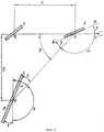
Изобретение поясняется фиг.1, 2, 3, 4, на которых представлена общая схема устройства (фиг.1), расчетная схема для определения расстояний между отражателями в зависимости от угловых наклонов к соответствующим осям (фиг.2), схема оптического клина (фиг.3) и вид поля зрения устройства на этапах наведения центратора на объект (фиг.4, а) и измерения расстояния от центратора до объекта (фиг.4, б).The invention is illustrated in figures 1, 2, 3, 4, which shows a general diagram of the device (Fig. 1), a design diagram for determining the distances between reflectors depending on the angular inclination to the corresponding axes (Fig. 2), a diagram of an optical wedge (Fig. .3) and the field of view of the device at the stages of pointing the centralizer at the object (Fig. 4, a) and measuring the distance from the centralizer to the object (Fig. 4, b).
Устройство содержит рентгеновский излучатель 1, к которому крепится корпус 2, в котором располагаются лазер 6 с двусторонним выходом излучения, первый отражатель 3 из оргстекла, установленный на оси рентгеновского пучка на расстоянии А от фокуса рентгеновского излучателя в точке пересечения осей рентгеновского пучка и лазера, оптический клин 4, установленный на оси лазера между первым отражателем и первым торцом лазера 6 на расстоянии А от центра первого отражателя, первый светоделитель 5, установленный на оси лазера между оптическим клином и первым торцом лазера, второй отражатель 8, установленный на оси лазера с возможностью вращения относительно оси, перпендикулярной плоскости, образуемой осями рентгеновского пучка и лазера, цилиндрическую линзу 7, установленную на оси лазера между его вторым торцом и вторым отражателем.The device comprises an x-ray emitter 1, to which a housing 2 is mounted, in which a laser 6 with a two-sided output of radiation is located, a first plexiglass reflector 3 mounted on the axis of the x-ray beam at a distance A from the focus of the x-ray emitter at the intersection of the axes of the x-ray beam and laser a wedge 4 mounted on the laser axis between the first reflector and the first end of the laser 6 at a distance A from the center of the first reflector, a
На оси рентгеновского пучка за первым отражателем остановлен второй светоделитель 9 из оргстекла.On the axis of the x-ray beam behind the first reflector, a second plexiglass beamsplitter 9 is stopped.
Устройство содержит также привод для вращения клина относительно оси лазера с частотой f≥10 Гц, шкалу с индексом для отсчета расстояния от рентгеновского излучателя до объекта 9. Эти элементы устройства не показаны на фиг.1 в силу общеизвестных соответствующих технических решений. Расстояние до объекта измеряется триангуляционным методом, как и в аналоге [1].The device also contains a drive for rotating the wedge relative to the laser axis with a frequency f≥10 Hz, a scale with an index for counting the distance from the x-ray emitter to object 9. These elements of the device are not shown in figure 1 due to well-known relevant technical solutions. The distance to the object is measured by the triangulation method, as in the analogue [1].
Устройство работает следующим образом.The device operates as follows.
Луч лазера, выходящий из его первого торца, частично отражается на второй светоделитель 9, после отражения от которого направляется на объект 10. При этом углы наклона отражающих поверхностей светоделителя 5 и второго светоделителя и расстояния между ними подобраны таким образом, что после отражения луча лазера от второго светоделителя 9 он совпадает с осью рентгеновского пучка (фиг.2). Прошедшая через светоделитель 5 часть излучения лазера 6 попадает на оптический клин 4 и после преломления в нем отклоняется на угол α/2, равный половине угла излучения рентгеновского пучка. При вращении оптического клина прошедший через него луч лазера формирует в пространстве полый конический пучок лучей, который после отражения от первого отражателя 3 проходит второй светоделитель 9 и направляется на объект 10, формируя на его поверхности светящееся кольцо. Т.к. расстояние от центра первого отражателя 3 до оптического клина равно расстоянию от этого центра до фокуса рентгеновского излучателя, а первый отражатель 3 установлен под углом 45° к оси лазера, то после отражения от него полый конический пучок лучей лазера распространяется соосно с рентгеновским пучком. Параиетры клина - его показатель преломления h и преломления угол θ подобраны так, что после преломления в клине 4 лучи лазера отклоняются на угол α/2, равный половине угла излучения рентгеновского пучка. В силу этого при вращении клина 4 формируется пучок лазерных лучей в виде полого конуса с углом при вершине θ, геометрия которого полностью идентична геометрии пучка рентгеновского излучения. Поэтому на поверхности объекта диаметр светящегося кольца, формируемого вращающимся клином 4, соответствует размерам зоны объекта, просвечиваемой пучком рентгеновского излучателя, а его центр совпадает с точкой пересечения объекта осью рентгеновского пучка. Эта точка в центре кольца подсвечивается лучом лазера, отраженного светоделителями 5 и 9.The laser beam emerging from its first end is partially reflected on the second beam splitter 9, after reflection from which it is directed to the object 10. Moreover, the angles of inclination of the reflecting surfaces of the
Излучение из второго торца лазера 6 проходит через цилиндрическую линзу 7, которая преобразует его в плоский расходящийся пучок света, который после отражения от подвижного второго отражателя формирует на объекте светящуюся полоску, которая перемещается по его поверхности параллельно самой себе при вращении второго отражателя 8. В момент совпадения этой полоски с центром светящегося кольца, подсвечиваемого отраженным от светоделителей 5 и 9 лучом лазера, отсчет по шкале устройства несет информацию о расстоянии от объекта до рентгеновского излучателя (фиг.4, а и б).The radiation from the second end of the laser 6 passes through a cylindrical lens 7, which converts it into a flat diverging beam of light, which after reflection from the movable second reflector forms a luminous strip on the object, which moves along its surface parallel to itself when the second reflector 8 is rotated. At the moment if this strip coincides with the center of the luminous ring illuminated by a laser beam reflected from
На фиг.2 представлена расчетная схема определения углов наклона светоделителей 4 и 9 к осям лазера и рентгеновского пучка соответственно, а также расстояний между ними.Figure 2 presents the calculation scheme for determining the angles of inclination of the beam splitters 4 and 9 to the axes of the laser and x-ray beam, respectively, as well as the distances between them.
При наклоне первого светоделителя 5, установленного на расстоянии С от центра первого отражателя 3 к оси лазера на угол β в силу симметрии геометрических соотношений при зеркальном отражении света [3] существует равенствоWhen tilting the
∠NKE=∠MKP=β.∠NKE = ∠MKP = β.
Сумма углов, прилегающих к прямой ДКР, равна 180°, поэтому ∠ДКЕ=180°-ε=φ.The sum of the angles adjacent to the straight DKR is 180 °, therefore ,DKE = 180 ° -ε = φ.
Но угол, прилегающий к прямой NM и EKP=E=180°-2β, что следует из анализа, отсюда ∠ДКЕ=2β=φ.But the angle adjacent to the straight line NM and EKP = E = 180 ° -2β, which follows from the analysis, hence ∠DKE = 2β = φ.
Из прямоугольного треугольника ДКЕ получаем B=c·tgφ=c·tg(2β) и ∠ДКЕ=ω=90°-φ=90°-2β.From the right-angled triangle DKE we get B = ctgφ = ctg (2β) and ∠DKE = ω = 90 ° -φ = 90 ° -2β.
Проводя аналогичный вышеизложенному анализ соотношенийй между углами, прилегающими к прямой RE, и углов между лучами, зеркально отраженными от второго светоделителя 9 в точке Е, получим ψ=180°-2γ, а также что ψ=90°-2β (углы при прямой RE).Carrying out an analysis similar to the foregoing of the relations between the angles adjacent to the straight line RE and the angles between the rays specularly reflected from the second beam splitter 9 at point E, we obtain ψ = 180 ° -2γ, and also that ψ = 90 ° -2β (angles with the straight line RE )
Окончательно получим, что γ=45°-β.Finally, we get that γ = 45 ° -β.
Угол отклонения луча δ от первоначального направления после преломления в клине (фиг.3) определяется известным соотношением [2]. δ=θ(n-1), где δ выбирается равным
В процессе работы оператор наводит на объект рентгеновский излучатель, совмещая светящееся кольцо с контролируемой зоной (фиг.4, а). Затем, вращая второй отражатель 8, совмещают лазерную полоску с лазерным пятном в центре светящегося кольца и снимают со шкалы значение расстояния от рентгеновского излучателя до объекта (фиг.4б).In the process, the operator induces an x-ray emitter at the object, combining a luminous ring with a controlled zone (Fig. 4, a). Then, rotating the second reflector 8, combine the laser strip with a laser spot in the center of the luminous ring and remove from the scale the value of the distance from the x-ray emitter to the object (fig.4b).
Частота вращения оптического клина f≥10 Гц выбрана с учетом получения сложного изображения светящегося кольца на поверхности объекта в соответствии с эргономическими характеристиками зрения [2].The frequency of rotation of the optical wedge f≥10 Hz is selected taking into account the complex image of the luminous ring on the surface of the object in accordance with the ergonomic characteristics of vision [2].
Источники информацииInformation sources
1. Патент РФ 2106619. Лазерный центратор.1. RF patent 2106619. Laser centralizer.
2. Справочник конструктора оптико-механических приборов. В.А. Панов и др. - Л.: Машиностроение, 1980, 742 с.2. Reference designer of optical-mechanical devices. V.A. Panov et al. - L.: Mechanical Engineering, 1980, 742 p.
Claims (1)
Translated fromRussianPriority Applications (1)
| Application Number | Priority Date | Filing Date | Title |
|---|---|---|---|
| RU2005112937/28ARU2289222C1 (en) | 2005-04-29 | 2005-04-29 | Laser positioner for x-radiator |
Applications Claiming Priority (1)
| Application Number | Priority Date | Filing Date | Title |
|---|---|---|---|
| RU2005112937/28ARU2289222C1 (en) | 2005-04-29 | 2005-04-29 | Laser positioner for x-radiator |
Publications (1)
| Publication Number | Publication Date |
|---|---|
| RU2289222C1true RU2289222C1 (en) | 2006-12-10 |
Family
ID=37665719
Family Applications (1)
| Application Number | Title | Priority Date | Filing Date |
|---|---|---|---|
| RU2005112937/28ARU2289222C1 (en) | 2005-04-29 | 2005-04-29 | Laser positioner for x-radiator |
Country Status (1)
| Country | Link |
|---|---|
| RU (1) | RU2289222C1 (en) |
Citations (6)
| Publication number | Priority date | Publication date | Assignee | Title |
|---|---|---|---|---|
| US4521905A (en)* | 1982-02-02 | 1985-06-04 | Horiba, Ltd. | Monitor of an X-ray radiation range |
| GB2175778A (en)* | 1985-05-18 | 1986-12-03 | British Aerospace | Radiographic apparatus |
| US5675625A (en)* | 1994-06-17 | 1997-10-07 | Lap Gmbh Laser Applikationen | Apparatus for positioning and marking a patient at a diagnostic apparatus |
| RU2106619C1 (en)* | 1996-04-22 | 1998-03-10 | Войсковая часть 75360 | Laser centralizer for x-radiator |
| RU2237985C1 (en)* | 2003-05-13 | 2004-10-10 | Войсковая часть 75360 | Laser localizer for x-ray radiator |
| RU2243629C2 (en)* | 2002-10-03 | 2004-12-27 | Войсковая часть 75360 | Laser localizer for x-ray generator |
- 2005
- 2005-04-29RURU2005112937/28Apatent/RU2289222C1/ennot_activeIP Right Cessation
Patent Citations (6)
| Publication number | Priority date | Publication date | Assignee | Title |
|---|---|---|---|---|
| US4521905A (en)* | 1982-02-02 | 1985-06-04 | Horiba, Ltd. | Monitor of an X-ray radiation range |
| GB2175778A (en)* | 1985-05-18 | 1986-12-03 | British Aerospace | Radiographic apparatus |
| US5675625A (en)* | 1994-06-17 | 1997-10-07 | Lap Gmbh Laser Applikationen | Apparatus for positioning and marking a patient at a diagnostic apparatus |
| RU2106619C1 (en)* | 1996-04-22 | 1998-03-10 | Войсковая часть 75360 | Laser centralizer for x-radiator |
| RU2243629C2 (en)* | 2002-10-03 | 2004-12-27 | Войсковая часть 75360 | Laser localizer for x-ray generator |
| RU2237985C1 (en)* | 2003-05-13 | 2004-10-10 | Войсковая часть 75360 | Laser localizer for x-ray radiator |
Similar Documents
| Publication | Publication Date | Title |
|---|---|---|
| JP2767235B2 (en) | Ring beam divergence angle control optical device | |
| JP5705261B2 (en) | Wide spectrometer | |
| RU2106619C1 (en) | Laser centralizer for x-radiator | |
| RU2136124C1 (en) | Laser centering skid for x-ray source | |
| US4478482A (en) | Axial scanning optical system and method of examining an object plane | |
| KR101691544B1 (en) | High-speed 3D imaging system having non-axially symmetric lens using THz beam scan | |
| KR20190048020A (en) | Inspection apparatus for hign speed and large area | |
| KR102465766B1 (en) | Measurement system for form error of optical surface using dove prism and beam expander | |
| JP2007538243A (en) | Apparatus and method for investigating a sample | |
| JPH02161332A (en) | Device and method for measuring radius of curvature | |
| JP7303641B2 (en) | Method and apparatus for inner diameter measurement of transparent tubing | |
| RU2289222C1 (en) | Laser positioner for x-radiator | |
| RU2242846C1 (en) | Laser localizer for x-ray radiation | |
| RU2289223C1 (en) | Scanning laser positioner for x-radiation | |
| RU2289221C1 (en) | Scanning laser x-ray positioner | |
| RU2263421C1 (en) | Laser localizer for x-ray emitter | |
| RU2179789C2 (en) | Laser centering mount for x-ray radiator | |
| RU2237985C1 (en) | Laser localizer for x-ray radiator | |
| RU2242845C1 (en) | Laser localizer for x-ray radiator | |
| RU2243629C2 (en) | Laser localizer for x-ray generator | |
| RU2293453C1 (en) | Laser localizer for x-ray emitter | |
| RU2369999C1 (en) | Laser positioner for x-ray emitter | |
| RU2241976C2 (en) | Laser localizer for x-ray emitter | |
| RU2369049C1 (en) | Laser centraliser for x-ray emitter | |
| JPH0328841A (en) | Schlieren device |
Legal Events
| Date | Code | Title | Description |
|---|---|---|---|
| MM4A | The patent is invalid due to non-payment of fees | Effective date:20070430 |