RU2288661C2 - Method for detecting safe areas for introducing fixators into a vertebra and a marking pattern for its implementation - Google Patents
Method for detecting safe areas for introducing fixators into a vertebra and a marking pattern for its implementationDownload PDFInfo
- Publication number
- RU2288661C2 RU2288661C2RU2003109095/14ARU2003109095ARU2288661C2RU 2288661 C2RU2288661 C2RU 2288661C2RU 2003109095/14 ARU2003109095/14 ARU 2003109095/14ARU 2003109095 ARU2003109095 ARU 2003109095ARU 2288661 C2RU2288661 C2RU 2288661C2
- Authority
- RU
- Russia
- Prior art keywords
- marks
- fixators
- roots
- needles
- introducing
- Prior art date
Links
Images


Landscapes
- Surgical Instruments (AREA)
Abstract
Description
Translated fromRussianИзобретение относится к области медицины, в частности к ортопедии и травматологии, а именно к хирургическим инструментам и способам лечения опорно-двигательного аппарата, и предназначено для проведения фиксаторов в тело позвонка.The invention relates to medicine, in particular to orthopedics and traumatology, in particular to surgical instruments and methods of treating the musculoskeletal system, and is intended for holding fixatives into the vertebral body.
Известен способ пункционного остеосинтеза, включающий прокол мягких тканей до кости, последовательное проведение путем вращения заостренных и удерживаемых за свободный конец спиц через костные отломки, в котором прокалывают мягкие ткани полой иглой и через ее просвет съемным держателем сначала всверливают спицу в кость до резьбовой части, затем ввинчивают резьбу в поверхностный кортикальный слой кости до упорной площадки, далее держатель и иглу снимают со свободного конца спицы и оставляют его под покровами тела, для этого используют устройство, включающее полую иглу с возможностью введения в нее спицы с упорной площадкой и рабочей части съемного держателя спицы, при этом длина иглы не менее длины вводимой спицы, в котором часть спицы у упорной площадки имеет резьбу, свободный конец спицы вместе с упорной площадкой выполнены с суммарной длиной, обеспечивающей возможность укрытия их в мягких тканях организма, а длина рабочей части держателя короче трубки полой иглы на длину резьбовой части спицы с упорной площадкой, при этом на рабочем конце держателя выполнена полость под свободный конец спицы (Заявка РФ 96108304, опубл. 10.07.1998).A known method of puncture osteosynthesis, including puncture of soft tissues to the bone, sequentially conducting through the rotation of pointed and held by the free end of the knitting needles through bone fragments, in which the soft tissue is pierced by a hollow needle and through its lumen with a removable holder, first drill the needle into the bone to the threaded part, then screw the thread into the superficial cortical layer of the bone to the thrust pad, then the holder and the needle are removed from the free end of the spoke and leave it under the covers of the body, for this use a device comprising a hollow needle with the possibility of introducing knitting needles into it with a thrust pad and the working part of a removable needle holder, wherein the length of the needle is not less than the length of the introduced knitting needle, in which a part of the knitting needle at the thrust pad is threaded, the free end of the knitting needle together with the thrust pad are made with the total length, providing the opportunity to shelter them in the soft tissues of the body, and the length of the working part of the holder is shorter than the tube of the hollow needle by the length of the threaded part of the spoke with a thrust pad, while a cavity is made on the working end of the holder at the free end of the spokes (RF Application 96,108,304, published. 07/10/1998).
Известно устройство и способ для внеочагового остеосинтеза позвоночник, содержащее резьбовые стержни, опорные элементы, винтовые тяги и элементы креплений, в котором опорные элементы выполнены в виде дугообразных пластин, с радиусом кривизны 140+10 мм и продольными прорезями, в которых перпендикулярно плоскости опорной пластины крепят резьбовые стержни, введенные в тела позвонков, со свободой движений в радиусе 30 градусов по отношению к опорной пластине за счет компенсаторных шайб, а опорные элементы имеют суммарную свободу перемещения в радиусе 60 градусов и связаны между собой кронштейнами с компенсаторными шайбами и продольными винтовыми тягами в двух параллельных плоскостях, которое позволяет осуществить способ внеочагового остеосинтеза позвоночника путем введения резьбовых стержней транспедикулярно в тела нескольких смежных неповрежденных позвонков с закреплением на внешней опоре (Заявка РФ 96113284, опубл. 27.10.1998).A device and method for extra-focal osteosynthesis of the spine, containing threaded rods, supporting elements, screw rods and fastening elements, in which the supporting elements are made in the form of arcuate plates with a radius of curvature of 140 + 10 mm and longitudinal slots in which are attached perpendicular to the plane of the base plate threaded rods inserted into the vertebral bodies with a freedom of movement within a radius of 30 degrees with respect to the base plate due to expansion washers, and the supporting elements have a total freedom of movement in a radius of 60 degrees and are interconnected by brackets with compensating washers and longitudinal screw rods in two parallel planes, which allows the method of extrafocal spinal osteosynthesis by introducing threaded rods transpedicularly into the bodies of several adjacent intact vertebrae with fastening to an external support (Application RF 96113284, publ. 10.27.1998).
Известен способ проведения резьбового стержня в тело позвонка и устройство для его осуществления, в котором используют предварительное введение направляющей осевой спицы, проводник с центральным продольным отверстием, защитную трубку, при помощи которой осуществляют защиту мягких тканей, контроль направления и глубины имплантации резьбового стержня, что обеспечивает необходимую точность его проведения через ножку дуги базового позвонка без продолжительного использования электронно-лучевого усилителя изображения, для этого устройство для остеосинтеза снабжают механизмом вращения в виде корпуса, содержащего храповик со стопором, четырехугольное гнездо с шариковым фиксатором на одном конце и рукоятку с циркулярными углублениями, установленную на противоположном конце перпендикулярно корпусу (Патент РФ 2051633, опубл. 10.01.1996).A known method of conducting a threaded rod into the body of the vertebra and a device for its implementation, which use the preliminary introduction of the guide axial spokes, a conductor with a central longitudinal hole, a protective tube with which to protect soft tissues, control the direction and depth of implantation of the threaded rod, which provides the necessary accuracy of its passage through the base of the arc of the base vertebra without prolonged use of the electron-beam image amplifier, for this purpose GUT for osteosynthesis rotation mechanism is provided with a housing comprising a ratchet with the stopper, a quadrangular jack with a ball retainer at one end and a handle with circular recesses, set on the opposite end perpendicular to the body (RF Patent 2051633, publ. 01.10.1996).
Однако известные способы и устройства предназначены для выполнения оперативного вмешательства в условиях операционной и не предусматривают предоперационную подготовку к введению фиксаторов в тела позвонков с использованием разметочного шаблона.However, the known methods and devices are designed to perform surgical intervention in the operating room and do not provide for preoperative preparation for the introduction of fixatives into the vertebral bodies using a marking template.
Анализ известных источников информации показал отсутствие разметочных шаблонов, использование которых позволяет осуществить предоперационную подготовку безопасного введения введения фиксаторов позвонка в костные структуры.Analysis of known sources of information showed the absence of marking patterns, the use of which allows preoperative preparation of the safe introduction of the introduction of vertebral fixatives into the bone structures.
Задачей настоящего изобретения является разработка способа определения безопасных зон введения фиксаторов в позвонок и разметочного шаблона для осуществления этого способа.The objective of the present invention is to develop a method for determining safe areas for the introduction of fixatives into the vertebra and a marking template for implementing this method.
Поставленная задача решается тем, что в способе определения безопасных зон введения фиксаторов в позвонок, состоящего в том, что выполняют рентгенограмму деформированного позвоночника во фронтальной плоскости, затем его контур идентифицируют с контуром разметочного шаблона, который совмещают с центрами корней дужек, после чего размещают на шаблоне спицы-метки в поперечной плоскости, совмещая их с центрами корней дужек, выполняют компьютерную томографию, на снимках которой определяют угол безопасного проведения фиксаторов, свободные концы спиц-меток изгибают, совмещая с углом безопасного проведения фиксаторов, в операционной на спине пациента размещают разметочный шаблон, совмещая его с контуром позвоночника, вводят, ориентируясь спиц-меток, фиксаторы в корни дужек, для этого используют разметочный шаблон, содержащий две опоры, выполненные из пластичного материала, в каждой из которых выполнены сквозные равномерно расположенные отверстия, при этом в последних между опор расположено не менее двух спиц-меток, свободные концы которых изогнуты.The problem is solved in that in the method for determining safe areas for introducing fixatives into the vertebra, consisting in the fact that they perform an x-ray of the deformed spine in the frontal plane, then its outline is identified with the outline of the marking template, which is combined with the centers of the roots of the arches, and then placed on the template knitting needles in the transverse plane, combining them with the centers of the roots of the arches, perform computed tomography, in the pictures of which the angle of safe holding of the clamps is determined, free the ends of the knitting needles are bent, combining with the angle of safe holding the retainers, in the operating room, on the patient’s back, place a marking template, combining it with the contour of the spine, insert, guided by knitting needles, fixators into the roots of the arches, for this use a marking template containing two supports, made of plastic material, in each of which through-hole uniformly spaced holes are made, while in the latter between the supports there are at least two knitting needles, the free ends of which are bent.
Настоящее изобретение поясняют подробным описанием, схемами и томограммами, на которых:The present invention is illustrated by a detailed description, diagrams and tomograms, in which:
Фиг.1 иллюстрирует наложение разметочного шаблона вдоль деформированного позвоночника;Figure 1 illustrates the imposition of a marking pattern along a deformed spine;
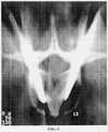
Фиг.2 характеризует компьютерную томограграмму, по которой определяют безопасную зону корня дужки для введения фиксатора;Figure 2 characterizes a computer tomogram, which determines the safe zone of the root of the arch for the introduction of the latch;
Фиг.3 иллюстрирует схему поперечного сечения позвонка и разметочного шаблона по линии АА, то же, что и на фиг.1, согласно изобретению;Figure 3 illustrates a diagram of a cross section of a vertebra and a marking template along line AA, the same as in figure 1, according to the invention;
Фиг.4 - компьютерная томогрэмма введенных фиксаторов позвонка.Figure 4 is a computer tomogram of inserted vertebral retainers.
Способ и устройство используют следующим образом.The method and device are used as follows.
Разметочный шаблон содержит две опоры 1, 2 (Фиг.1). Каждая из опор 1, 2 выполнена из пластичного материала (алюминий, медь и др.). Кроме того, каждая из опор 1, 2 может быть выполнена в виде пластины или стержня небольшого диаметра. В каждой из них выполнены сквозные равномерно расположенные отверстия 3, 4. При этом в последних между опор 1, 2 расположено не менее двух спиц-меток 5, свободные концы которых изогнуты.The marking template contains two
Опоры 1, 2, выполненные из пластичного материала, наложены на контуры деформированного позвоночника.
При выполнении способа определения безопасного места введения стержней-шурупов в корни дужки позвонков выполняют рентгенограммы. Затем на фронтальную проекцию рентгенограммы больного со сколиотической деформацией позвоночника накладывают опоры 1, 2 (Фиг.1) разметочного шаблона, которые выполняют из гибкого материала. Опоры 1 и 2 изогнули в соответствии с контуром деформированного позвоночника. При этом они совмещены с центром корней дужек позвонков. Затем в предполагаемые для проведения стержней-шурупов позвонки через отверстия 3, 4 в разметочном шаблоне провели спицу-метку 5 на пересечении центра корней дужек в горизонтальной плоскости. По компьютерным томограммам фиг.2 определили угол введения стержней-шурупов в тело позвонка 6 через корни дужек. Концы спицы-метки 5 загнули под углом, определенным по рентгенограммам компьютерного томографа, соответствующим углу безопасной области введения фиксаторов 7, 8 в тело позвонка.When performing the method of determining the safe place for the introduction of the rods-screws into the roots of the arch of the vertebrae, radiographs are performed. Then, on the frontal projection of a radiograph of a patient with scoliotic spinal deformity, the supports 1, 2 (Fig. 1) of the marking template, which are made of flexible material, are applied. Supports 1 and 2 bent in accordance with the contour of the deformed spine. Moreover, they are combined with the center of the roots of the vertebral arches. Then, into the vertebrae supposed for holding the screw-rods through the
На операционном столе, пальпируя остистые отростки позвонков, накладываем приготовленный разметочный шаблон вдоль контура деформированного позвоночника, отмечаем уровни введения фиксаторов 7, 8, в виде стержней-шурупов, устанавливаем не менее двух спиц-меток 5, учитывая угол безопасной зоны проведения стержней-шурупов 7, 8 в тела позвонков. После рентгенологического контроля ввели через корни дужек стержни-шурупы 7, 8 (Фиг.3) в тела позвонков.On the operating table, palpating the spinous processes of the vertebrae, we impose the prepared marking pattern along the contour of the deformed spine, note the levels of insertion of fixatives 7, 8, in the form of screw rods, set at least two
Пример использования способа и разметочного шаблона.An example of using the method and layout template.
Клинический пример. Больная К., 15 лет, находится на лечении с диагнозом: Диспластический "S"-образный грудопоясничный сколиоз III степени. Правосторонний реберный горб.Clinical example. Patient K., 15 years old, is undergoing treatment with a diagnosis of Dysplastic "S" -shaped thoracolumbar scoliosis of the III degree. Right costal hump.
При поступлении предъявляла жалобы на деформацию позвоночника в грудном и поясничном отделах. Считает себя больной в течение пяти лет. Лечилась консервативно, без эффекта. Госпитализирована в отделение нейрохирургии для обследования и оперативного лечения в плановом порядке.On admission, she complained of spinal deformity in the thoracic and lumbar regions. Considers herself ill for five years. Treated conservatively, without effect. She was hospitalized in the department of neurosurgery for examination and surgical treatment in a planned manner.
Клиническая картина заболевания при поступлении представлена искривлением позвоночника в грудном и поясничном отделах. Асимметрия треугольников талии и надплечий. Правосторонний реберный горб. В неврологическом статусе грубой патологии нет.The clinical picture of the disease at admission is represented by curvature of the spine in the thoracic and lumbar regions. Asymmetry of the triangles of the waist and shoulders. Right costal hump. There is no gross pathology in the neurological status.
На спондилограммах грудного и поясничного отделов позвоночника определяется "S"-образный сколиоз грудного и поясничного отделов позвоночника с вершиной деформации в грудном отделе на D9, углом 44° и дугой противопоставления с вершиной на L2, углом 36°.On spondylograms of the thoracic and lumbar spine, an "S" -shaped scoliosis of the thoracic and lumbar spine with the apex of deformation in the thoracic spine at D9, angle of 44 ° and the arch of contrast with the apex at L2, angle of 36 ° is determined.
24.12.02 г. под эндотрахеальным наркозом выполнен I этап оперативного лечения - поднадкостничная резекция 7, 8, 9, 10, 11 ребер справа на участке до 10-12 см. Послеоперационный период - без осложнений.12.24.02, under endotracheal anesthesia, I stage of surgical treatment was performed - subperiosteal resection of 7, 8, 9, 10, 11 ribs on the right in the area up to 10-12 cm. Postoperative period - without complications.
17.01.03 г.выполнен II этап оперативного лечения - закрытое наложение аппарата наружной транспедикулярной фиксации позвоночника. С целью безопасного проведения стержней-шурупов в тела позвонков в предоперационном периоде использовали разметочный шаблон.01/17/03, the second stage of surgical treatment was performed - closed application of the external transpedicular fixation apparatus of the spine. In order to safely conduct the screw rods into the vertebral bodies in the preoperative period, a marking template was used.
На фронтальную проекцию рентгенограммы больной накладывали разметочный шаблон, моделируя опоры в соответствии с контуром деформированного позвоночника, совмещая их с центром корней дужек позвонков. Затем в предполагаемые для проведения стержней-шурупов позвонки через отверстия в разметочном шаблоне проводили спицы на пересечении центра корней дужек в горизонтальной плоскости. По компьютерным томограммам определяли угол введения стержней-шурупов в тело позвонка и концы спицы изгибали под углом, определенным по рентгенограммам компьютерного томографа.A marking template was applied to the frontal projection of the radiograph of the patient, modeling the supports in accordance with the contour of the deformed spine, combining them with the center of the roots of the vertebral arches. Then, into the vertebrae proposed for holding the screw rods through the holes in the marking template, knitting needles were made at the intersection of the center of the roots of the arches in the horizontal plane. Using computer tomograms, the angle of introduction of the screw rods into the vertebral body was determined, and the ends of the spokes were bent at an angle determined by radiographs of a computer tomograph.
На операционном столе, пальпируя остистые отростки позвонков, накладывали приготовленный разметочный шаблон вдоль контура деформированного позвоночника, отмечали уровни введения стержней-шурупов, устанавливали спицы-метки, учитывая угол безопасной зоны проведения стержней-шурупов в тела позвонков. После рентгенологического контроля вводили через корни дужек стержни-шурупы в тела позвонков (Фиг.4).On the operating table, palpating the spinous processes of the vertebrae, the prepared marking template was applied along the contour of the deformed spine, the levels of insertion of the screw rods were noted, the knitting needles were set, taking into account the angle of the safe area for holding the rod rods in the vertebral bodies. After x-ray control, rods-screws were inserted through the roots of the arches into the vertebral bodies (Figure 4).
Предлагаемые способ и разметочный шаблон позволяют сократить продолжительность оперативного вмешательства, уменьшить количество рентгенологических исследований во время вмешательства. Разметочный шаблон прост в изготовлении и эксплуатации.The proposed method and layout template can reduce the duration of surgery, reduce the number of x-ray studies during the intervention. The marking template is easy to manufacture and operate.
Claims (2)
Translated fromRussianPriority Applications (1)
| Application Number | Priority Date | Filing Date | Title |
|---|---|---|---|
| RU2003109095/14ARU2288661C2 (en) | 2003-03-31 | 2003-03-31 | Method for detecting safe areas for introducing fixators into a vertebra and a marking pattern for its implementation |
Applications Claiming Priority (1)
| Application Number | Priority Date | Filing Date | Title |
|---|---|---|---|
| RU2003109095/14ARU2288661C2 (en) | 2003-03-31 | 2003-03-31 | Method for detecting safe areas for introducing fixators into a vertebra and a marking pattern for its implementation |
Publications (2)
| Publication Number | Publication Date |
|---|---|
| RU2003109095A RU2003109095A (en) | 2004-09-27 |
| RU2288661C2true RU2288661C2 (en) | 2006-12-10 |
Family
ID=37665748
Family Applications (1)
| Application Number | Title | Priority Date | Filing Date |
|---|---|---|---|
| RU2003109095/14ARU2288661C2 (en) | 2003-03-31 | 2003-03-31 | Method for detecting safe areas for introducing fixators into a vertebra and a marking pattern for its implementation |
Country Status (1)
| Country | Link |
|---|---|
| RU (1) | RU2288661C2 (en) |
Cited By (2)
| Publication number | Priority date | Publication date | Assignee | Title |
|---|---|---|---|---|
| RU2476179C1 (en)* | 2011-08-08 | 2013-02-27 | Федеральное государственное учреждение "Российский научный центр "Восстановительная травматология и ортопедия" имени академика Г.А. Илизарова" Министерства здравоохранения и социального развития Российской Федерации" | Method of transcutaneous introduction of fixers and device for its realisation |
| RU2794557C1 (en)* | 2022-12-16 | 2023-04-21 | федеральное государственное бюджетное учреждение "Национальный медицинский исследовательский центр имени В.А. Алмазова" Министерства здравоохранения Российской Федерации | Method for controlled pulmonary thromboendarterectomy in the treatment of chronic thromboembolic pulmonary hypertension |
Citations (6)
| Publication number | Priority date | Publication date | Assignee | Title |
|---|---|---|---|---|
| US4969888A (en)* | 1989-02-09 | 1990-11-13 | Arie Scholten | Surgical protocol for fixation of osteoporotic bone using inflatable device |
| RU2051633C1 (en)* | 1991-09-30 | 1996-01-10 | Николай Степанович Клепач | Method and device for passing threaded bar into vertebra body |
| RU2093901C1 (en)* | 1993-02-01 | 1997-10-20 | Российский научный центр "Восстановительная травматология и ортопедия" им.акад.Г.А.Илизарова | Method of modeling tee closed introduction of fixatives into vertebra body |
| RU2106828C1 (en)* | 1993-05-26 | 1998-03-20 | Курганский государственный научный центр "Восстановительная травматология и ортопедия" | Device for determining level to which closed introduction of fixing members into vertebral arch roots is possible |
| US5980572A (en)* | 1997-04-15 | 1999-11-09 | Asahi Kogaku Kogyo Kabushiki Kaisha | Artificial spines |
| US6607530B1 (en)* | 1999-05-10 | 2003-08-19 | Highgate Orthopedics, Inc. | Systems and methods for spinal fixation |
- 2003
- 2003-03-31RURU2003109095/14Apatent/RU2288661C2/ennot_activeIP Right Cessation
Patent Citations (6)
| Publication number | Priority date | Publication date | Assignee | Title |
|---|---|---|---|---|
| US4969888A (en)* | 1989-02-09 | 1990-11-13 | Arie Scholten | Surgical protocol for fixation of osteoporotic bone using inflatable device |
| RU2051633C1 (en)* | 1991-09-30 | 1996-01-10 | Николай Степанович Клепач | Method and device for passing threaded bar into vertebra body |
| RU2093901C1 (en)* | 1993-02-01 | 1997-10-20 | Российский научный центр "Восстановительная травматология и ортопедия" им.акад.Г.А.Илизарова | Method of modeling tee closed introduction of fixatives into vertebra body |
| RU2106828C1 (en)* | 1993-05-26 | 1998-03-20 | Курганский государственный научный центр "Восстановительная травматология и ортопедия" | Device for determining level to which closed introduction of fixing members into vertebral arch roots is possible |
| US5980572A (en)* | 1997-04-15 | 1999-11-09 | Asahi Kogaku Kogyo Kabushiki Kaisha | Artificial spines |
| US6607530B1 (en)* | 1999-05-10 | 2003-08-19 | Highgate Orthopedics, Inc. | Systems and methods for spinal fixation |
Cited By (2)
| Publication number | Priority date | Publication date | Assignee | Title |
|---|---|---|---|---|
| RU2476179C1 (en)* | 2011-08-08 | 2013-02-27 | Федеральное государственное учреждение "Российский научный центр "Восстановительная травматология и ортопедия" имени академика Г.А. Илизарова" Министерства здравоохранения и социального развития Российской Федерации" | Method of transcutaneous introduction of fixers and device for its realisation |
| RU2794557C1 (en)* | 2022-12-16 | 2023-04-21 | федеральное государственное бюджетное учреждение "Национальный медицинский исследовательский центр имени В.А. Алмазова" Министерства здравоохранения Российской Федерации | Method for controlled pulmonary thromboendarterectomy in the treatment of chronic thromboembolic pulmonary hypertension |
Similar Documents
| Publication | Publication Date | Title |
|---|---|---|
| Kamimura et al. | Accurate pedicle screw insertion under the control of a computer-assisted image guiding system: laboratory test and clinical study | |
| Berry et al. | Personalised image-based templates for intra-operative guidance | |
| Lehmann et al. | Comparison of open versus percutaneous pedicle screw insertion in a sheep model | |
| Ciolli et al. | Navigated percutaneous screw fixation of the pelvis with O-arm 2: two years’ experience | |
| Khanna et al. | Effect of intraoperative navigation on operative time in 1-level lumbar fusion surgery | |
| TWI611793B (en) | Guiding apparatus for minimally invasive pedicle screws insertion | |
| Feng et al. | 3-Dimensional printing templates guiding versus free hand technique for cervical lateral mass screw fixation: A prospective study | |
| RU2662203C1 (en) | Method of c1-c2 transarticular vertebral fixation | |
| US20230210508A1 (en) | Surgical system | |
| RU2377961C1 (en) | Transpedicular vertebral fixation technique | |
| RU2288661C2 (en) | Method for detecting safe areas for introducing fixators into a vertebra and a marking pattern for its implementation | |
| RU2726473C1 (en) | Method for determination of instrument trajectory in spinal surgery on open wound | |
| RU2678467C1 (en) | Method of conducting transpedicular fixation of lower cervical spine | |
| Visco et al. | Integration of Machine Vision Technology in the Treatment of Pediatric Spinal Deformities | |
| JP2013528074A (en) | Minimally invasive spinal surgery instrument and use thereof | |
| RU2384305C1 (en) | Method of twin-screw fixation of c2 vertebral dens fracture and related apparatus for introducing one pin for twin-screw fixation of c2 vertebral dens fracture | |
| RU2796873C1 (en) | Set for installation of a plate for osteosynthesis in the treatment of valgus deformity of the first toe and a method of its use | |
| CN207561969U (en) | Pedicle screw minimally invasive positioning device | |
| RU2828969C1 (en) | Method for surgical treatment of idiopathic spinal scoliosis using 3d prototyping of spinal model for insertion of transpedicular screws | |
| RU2747071C1 (en) | Method of insertion of transpedicular screws in the chest and lumbar spine | |
| RU2751279C1 (en) | Method for determining the level of the functional spinal unit in spinal operations | |
| RU2145813C1 (en) | Method of treating fractures of vertebral column thoracic part | |
| RU2140225C1 (en) | Method and device for determination of affection focus in vertebral column | |
| RU2547725C1 (en) | Method of closed intramedullary osteosynthesis in case of fractures of proximal part of humeral bone | |
| RU2204341C2 (en) | Method for finding the way to introduce transpediculate screws at pediculocorporal osteosynthesis of posterior-thoracic and lumbar vertebrae |
Legal Events
| Date | Code | Title | Description |
|---|---|---|---|
| MM4A | The patent is invalid due to non-payment of fees |