RU2284161C1 - Mobile vacuum hardware complex for temporary immobilizing local myocardium zones in doing operations without cardiac arrest - Google Patents
Mobile vacuum hardware complex for temporary immobilizing local myocardium zones in doing operations without cardiac arrestDownload PDFInfo
- Publication number
- RU2284161C1 RU2284161C1RU2005107635/14ARU2005107635ARU2284161C1RU 2284161 C1RU2284161 C1RU 2284161C1RU 2005107635/14 ARU2005107635/14 ARU 2005107635/14ARU 2005107635 ARU2005107635 ARU 2005107635ARU 2284161 C1RU2284161 C1RU 2284161C1
- Authority
- RU
- Russia
- Prior art keywords
- vacuum
- complex
- unit
- stabilizer
- central compartment
- Prior art date
Links
- 210000004165myocardiumAnatomy0.000titleclaimsdescription15
- 208000010496Heart ArrestDiseases0.000titleclaimsdescription8
- 230000003100immobilizing effectEffects0.000titleclaimsdescription6
- 239000003381stabilizerSubstances0.000claimsabstractdescription45
- 210000002445nippleAnatomy0.000claimsdescription12
- 238000012544monitoring processMethods0.000claimsdescription10
- 230000002107myocardial effectEffects0.000claimsdescription8
- 230000001105regulatory effectEffects0.000claimsdescription4
- 238000009423ventilationMethods0.000claimsdescription4
- 230000000472traumatic effectEffects0.000abstractdescription7
- 230000000694effectsEffects0.000abstractdescription2
- 239000000126substanceSubstances0.000abstract1
- 238000001356surgical procedureMethods0.000description4
- 238000007675cardiac surgeryMethods0.000description3
- 238000011161developmentMethods0.000description3
- 238000000034methodMethods0.000description3
- 230000000747cardiac effectEffects0.000description2
- 238000013461designMethods0.000description2
- 238000010586diagramMethods0.000description2
- 230000000712assemblyEffects0.000description1
- 238000000429assemblyMethods0.000description1
- 210000000038chestAnatomy0.000description1
- 239000003814drugSubstances0.000description1
- 238000005516engineering processMethods0.000description1
- 230000007717exclusionEffects0.000description1
- 239000004973liquid crystal related substanceSubstances0.000description1
- 239000000463materialSubstances0.000description1
- 239000011159matrix materialSubstances0.000description1
- 230000003680myocardial damageEffects0.000description1
- 208000037891myocardial injuryDiseases0.000description1
- 210000000056organAnatomy0.000description1
- 238000012546transferMethods0.000description1
- 230000000007visual effectEffects0.000description1
Images


Classifications
- A—HUMAN NECESSITIES
- A61—MEDICAL OR VETERINARY SCIENCE; HYGIENE
- A61B—DIAGNOSIS; SURGERY; IDENTIFICATION
- A61B17/00—Surgical instruments, devices or methods
- A61B17/02—Surgical instruments, devices or methods for holding wounds open, e.g. retractors; Tractors
- A61B17/0293—Surgical instruments, devices or methods for holding wounds open, e.g. retractors; Tractors with ring member to support retractor elements
- A—HUMAN NECESSITIES
- A61—MEDICAL OR VETERINARY SCIENCE; HYGIENE
- A61B—DIAGNOSIS; SURGERY; IDENTIFICATION
- A61B17/00—Surgical instruments, devices or methods
- A61B17/02—Surgical instruments, devices or methods for holding wounds open, e.g. retractors; Tractors
- A—HUMAN NECESSITIES
- A61—MEDICAL OR VETERINARY SCIENCE; HYGIENE
- A61B—DIAGNOSIS; SURGERY; IDENTIFICATION
- A61B17/00—Surgical instruments, devices or methods
- A61B17/00234—Surgical instruments, devices or methods for minimally invasive surgery
- A61B2017/00238—Type of minimally invasive operation
- A61B2017/00243—Type of minimally invasive operation cardiac
- A—HUMAN NECESSITIES
- A61—MEDICAL OR VETERINARY SCIENCE; HYGIENE
- A61B—DIAGNOSIS; SURGERY; IDENTIFICATION
- A61B17/00—Surgical instruments, devices or methods
- A61B17/02—Surgical instruments, devices or methods for holding wounds open, e.g. retractors; Tractors
- A61B2017/0237—Surgical instruments, devices or methods for holding wounds open, e.g. retractors; Tractors for heart surgery
- A61B2017/0243—Surgical instruments, devices or methods for holding wounds open, e.g. retractors; Tractors for heart surgery for immobilizing local areas of the heart, e.g. while it beats
- A—HUMAN NECESSITIES
- A61—MEDICAL OR VETERINARY SCIENCE; HYGIENE
- A61B—DIAGNOSIS; SURGERY; IDENTIFICATION
- A61B17/00—Surgical instruments, devices or methods
- A61B17/30—Surgical pincettes, i.e. surgical tweezers without pivotal connections
- A61B2017/306—Surgical pincettes, i.e. surgical tweezers without pivotal connections holding by means of suction
Landscapes
- Health & Medical Sciences (AREA)
- Life Sciences & Earth Sciences (AREA)
- Surgery (AREA)
- Heart & Thoracic Surgery (AREA)
- Engineering & Computer Science (AREA)
- Biomedical Technology (AREA)
- Nuclear Medicine, Radiotherapy & Molecular Imaging (AREA)
- Medical Informatics (AREA)
- Molecular Biology (AREA)
- Animal Behavior & Ethology (AREA)
- General Health & Medical Sciences (AREA)
- Public Health (AREA)
- Veterinary Medicine (AREA)
- Accommodation For Nursing Or Treatment Tables (AREA)
Abstract
Description
Translated fromRussianИзобретение относится к области медицины и может быть использовано в кардиохирургии при проведении полномасштабных и малоинвазийных операций без остановки сердца в специализированных центрах, в региональных хирургических клиниках, в передвижных кардиохирургических комплексах.The invention relates to medicine and can be used in cardiac surgery when conducting full-scale and minimally invasive operations without cardiac arrest in specialized centers, in regional surgical clinics, in mobile cardiosurgical complexes.
В настоящее время перспективным направлением кардиохирургии являются операции без остановки сердца с иммобилизацией оперируемого участка миокарда, что позволяет существенно снизить травмирующее воздействие на пациента. Для выполнения таких операций используют вакуумные аппаратные комплексы и устройства для иммобилизации локальных зон миокарда с помощью вакуумных присосок. Основные проблемы, которые приходится решать при разработке вакуумных аппаратных комплексов для кардиохирургических операций, заключаются в повышении надежности временной иммобилизации оперируемого локального участка миокарда, в пределе - полное исключение любого перемещения поверхности оперируемого участка миокарда при минимальном травматическом воздействии на сердце и сохранении по возможности нормальных условий работы сердца, а также обеспечение для хирурга максимальных возможностей сосредоточиться непосредственно на выполнении операции на миокарде при минимальном отвлечении внимания хирурга при подготовке к операции.Currently, a promising area of cardiac surgery are operations without cardiac arrest with the immobilization of the operated myocardial site, which can significantly reduce the traumatic effect on the patient. To perform such operations, vacuum hardware complexes and devices for immobilizing local myocardial zones using vacuum suction cups are used. The main problems that have to be solved when developing vacuum hardware systems for cardiosurgical operations are to increase the reliability of temporary immobilization of the operated local myocardium, the limit is the complete exclusion of any movement of the surface of the operated myocardial site with minimal traumatic effect on the heart and maintaining normal working conditions as much as possible heart, as well as providing the surgeon with maximum opportunities to focus directly on the execution enii operations on myocardium with minimal distraction surgeon in preparation for surgery.
Известен вакуумный аппаратный комплекс для временной иммобилизации органа, например сердца, содержащий закрепленный на силовой опоре лепестковый вакуумный стабилизатор для перемещения и удерживания сердца в зоне операции, имеющий силовое плечо с вакуумной чашеобразной присоской на конце плеча. Вакуумная чашеобразная присоска по форме совпадает с вершиной сердца и подключена с помощью отсасывающего гибкого трубопровода к вакуумному источнику (см. заявку РСТ № WO 01/17437 А2, А 61 В 17/02, 15.03.2001). При операции на сердце чашеобразная присоска устанавливается на вершине сердца, в полости вакуумной присоски создается разрежение, в силу чего сердце фиксируется относительно присоски, но может продолжать работать. Далее сердце перемещают в операционную зону и хирург имеет возможность проводить операцию в более удобной зоне, в том числе на работающем сердце, если эта зона находится вблизи присоски. В данном вакуумном аппаратном комплексе, как и в большинстве других известных вакуумных аппаратных комплексах для кардиохирургии, в качестве вакуумного источника используют стационарную вакуумную систему клиники, давление в которой всегда поддерживается неизменным вне зависимости от требований к конкретной операции. Кроме того, если зона операции не совпадает с чашеобразной присоской, необходимо использование каких-либо других средств.A vacuum apparatus complex is known for temporarily immobilizing an organ, for example, a heart, comprising a petal vacuum stabilizer fixed to a power support for moving and holding the heart in the operation area, having a power shoulder with a vacuum cup-shaped suction cup at the end of the shoulder. The vacuum cup-shaped suction cup coincides in shape with the top of the heart and is connected by a suction flexible pipe to a vacuum source (see PCT application No. WO 01/17437 A2, A 61
Известен также вакуумный аппаратный комплекс, содержащий вакуумный источник, закрепленный на ранорасширителе вакууумный стабилизатор для иммобилизации локального участка миокарда с удерживающими оперируемый участок миокарда двумя вакуумными присосками и отсасывающий гибкий трубопровод, соединяющий вакуумные присоски с вакуумным источником (см. заявку РСТ № WO 00/15119 A1, А 61 В 17/02, 23.03.2000). Наличие двух вакуумных присосок дает возможность уменьшить зону воздействия разреженного воздействия на миокард и тем самым уменьшить травматическое воздействие присосок на миокард. Однако, как и во всех комплексах со стационарным вакуумным источником, известный вакуумный аппаратный комплекс не дает возможности подобрать уровень разрежения в соответствии с конкретными условиями операции и не позволяет контролировать действующий уровень разрежения, что повышает риск травматического повреждения миокарда при проведении операции. Необходимость наличия стационарного вакуумного источника исключает возможность использования данного изобретения в передвижных кардиологических комплексах. Кроме того, необходимо дополнительное средство для перемещения сердца в удобное для операции положение.Also known is a vacuum apparatus complex containing a vacuum source, a vacuum stabilizer fixed to the retractor to immobilize the local myocardial region with two vacuum suction cups holding the operated myocardial region and a suction flexible pipe connecting the vacuum suction cups to a vacuum source (see PCT application No. WO 00/15119 A1 , A 61
Наиболее близким к предложенному изобретению по совокупности существенных признаков является мобильный вакуумный аппаратный комплекс для временной иммобилизации локальных участков миокарда при операциях без остановки сердца, содержащий лепестковый вакуумный стабилизатор положения сердца и рамочный вакуумный стабилизатор для иммобилизации локального участка миокарда, присоски которых подключены к ниппелям установленного в переносном контейнере автономного вакуумного источника, включающего в себя вакуумный агрегат, оснащенный основным и дублирующим вакуумными насосами, коллектор, соединенный с вакуумными насосами через электрически управляемые нормально закрытые клапаны регулирования уровня разрежения в коллекторе, электрически управляемый нормально закрытый клапан сброса вакуума в коллекторе, систему управления и контроля, имеющую датчик уровня разрежения в коллекторе и электронный блок управления, оснащенный микропроцессором, дисплейным индикатором режимов работы комплекса и клавиатурой задания функциональных характеристик комплекса, и устройство регистрации функциональных характеристик комплекса во время операции (см. патент Российской Федерации №2216284, А 61 В 17/02, 20.11.2003). Известное устройство содержит комплекс средств для проведения операции на работающем сердце. Лепестковый вакуумный стабилизатор обеспечивает перемещение работающего сердца в положение, удобное для операции, и удерживание его в этом положении в течение всей операции. Рамочный стабилизатор обеспечивает надежную иммобилизацию оперируемого локального участка миокарда. Описанная в патенте конструкция вакуумного источника обеспечивает эксплуатацию его в автономном режиме с выбором наиболее приемлемого уровня разрежения для работы присосок рамочного вакуумного стабилизатора. Однако в данном комплексе не обеспечивается оптимальный уровень разрежения в присосках лепесткового вакуумного стабилизатора.Closest to the proposed invention in terms of essential features is a mobile vacuum hardware complex for temporary immobilization of local areas of the myocardium during operations without cardiac arrest, containing a petal vacuum stabilizer of the position of the heart and frame vacuum stabilizer for immobilization of the local area of the myocardium, suction cups of which are connected to nipples installed in a portable a container of an autonomous vacuum source including a vacuum unit equipped with main and duplicate vacuum pumps, a collector connected to vacuum pumps through electrically controlled normally closed rarefaction valves in the manifold, electrically controlled normally closed vacuum relief valve in the manifold, a control and monitoring system having a manifold vacuum level sensor and an electronic control unit, equipped with a microprocessor, a display indicator of the operating modes of the complex and a keyboard for setting the functional characteristics of the complex, and a device p recording is the set of functional characteristics during operation (see. patent of the Russian Federation No. 2216284, A 61
Задачей, на решение которой направлено настоящее изобретение, является разработка мобильного вакуумного аппаратного комплекса для временной иммобилизации локального участка миокарда при операциях без остановки сердца с минимальным травматическим воздействием на сердце, позволяющего при проведении конкретной операции задавать и поддерживать в автономном режиме в течение всей операции оптимальные функциональные характеристики комплекса для каждого стабилизатора, наиболее соответствующие состоянию оперируемого сердца, с регистрацией характеристик каждого стабилизатора при минимальном количестве транспортабельных функциональных блоков и минимальной нагрузке на хирурга. Другой задачей изобретения является разработка мобильного вакуумного аппаратного комплекса, обеспечивающего хирургу комфортные условия при подготовке и проведении операции. Дополнительной задачей изобретения является разработка мобильного вакуумного аппаратного комплекса с минимальной массой транспортабельного функционального блока, в частности переносного контейнера с автономным вакуумным источником. Еще одной задачей изобретения является оптимизация состава транспортабельных блоков, чтобы расширить возможности проведения операций на сердце не только в крупных специализированных центрах, но и в региональных хирургических клиниках, а также в передвижных кардиохирургических комплексах.The problem to which the present invention is directed is the development of a mobile vacuum hardware complex for temporary immobilization of a local myocardial site during operations without cardiac arrest with minimal traumatic effect on the heart, which allows, during a specific operation, to set and maintain autonomous optimal functional functions during the entire operation the characteristics of the complex for each stabilizer, the most appropriate state of the operated heart, from the register iey characteristics of each stabilizer with a minimum number of functional units transportable and minimum load on the surgeon. Another objective of the invention is the development of a mobile vacuum hardware complex that provides the surgeon with comfortable conditions during the preparation and conduct of the operation. An additional objective of the invention is the development of a mobile vacuum hardware complex with a minimum mass of transportable functional unit, in particular a portable container with an autonomous vacuum source. Another objective of the invention is to optimize the composition of transportable blocks in order to expand the possibilities of performing heart operations not only in large specialized centers, but also in regional surgical clinics, as well as in mobile cardiosurgical complexes.
Поставленные технические задачи решаются тем, что в мобильном вакуумном аппаратном комплексе для временной иммобилизации локальных участков миокарда при операциях без остановки сердца, содержащем лепестковый вакуумный стабилизатор положения сердца и рамочный вакуумный стабилизатор для иммобилизации локального участка миокарда, подключенные к ниппелям установленного в переносном контейнере автономного вакуумного источника, включающего в себя первый вакуумный агрегат, оснащенный основным и дублирующим вакуумными насосами, коллектором, соединенным с вакуумными насосами через электрически управляемые нормально закрытые клапаны регулирования уровня разрежения в коллекторе, и электрически управляемым нормально закрытым клапаном сброса вакуума в коллекторе, системой управления и контроля, имеющей датчик уровня разрежения в коллекторе и электронный блок управления, оснащенный микропроцессором, дисплейным индикатором режимов работы вакуумного агрегата и клавиатурой задания функциональных характеристик вакуумного агрегата, и устройство регистрации функциональных характеристик вакуумного агрегата во время операции, согласно изобретению, в автономный вакуумный источник введен второй вакуумным агрегат, связанный с лепестковым вакуумным стабилизатором положения сердца, также оснащенный основным и дублирующим вакуумными насосами, коллектором, соединенным с вакуумными насосами через электрически управляемые нормально закрытые клапаны регулирования уровня разрежения в коллекторе, и электрически управляемым нормально закрытым клапаном сброса вакуума в коллекторе, системой управления и контроля, имеющей датчик уровня разрежения в коллекторе и электронный блок управления, при этом рамочный вакуумный стабилизатор для иммобилизации локального участка миокарда подключен к первому вакуумному агрегату, а системы управления и контроля подключены к устройству регистрации функциональных характеристик комплекса с возможностью поочередного опроса электронных блоков управления первого и второго вакуумных агрегатов.The stated technical problems are solved by the fact that in a mobile vacuum hardware complex for temporary immobilization of local areas of the myocardium during operations without cardiac arrest, containing a petal vacuum stabilizer of the position of the heart and a frame vacuum stabilizer for immobilization of the local area of the myocardium connected to the nipples of an autonomous vacuum source installed in a portable container , which includes the first vacuum unit, equipped with a main and backup vacuum pumps, collector a torus connected to vacuum pumps through electrically controlled normally closed vacuum valves for regulating the vacuum level in the collector, and electrically controlled normally closed vacuum valve for relieving the vacuum in the manifold, a control and monitoring system having a vacuum level sensor in the collector and an electronic control unit equipped with a microprocessor, a display indicator operating modes of the vacuum unit and a keyboard for setting the functional characteristics of the vacuum unit, and a recording device characteristics of the vacuum unit during the operation according to the invention, a second vacuum unit connected to the petal vacuum stabilizer of the heart position, also equipped with a main and backup vacuum pumps, a collector connected to vacuum pumps through electrically controlled normally closed level control valves, is introduced into the autonomous vacuum source rarefaction in the manifold, and an electrically operated normally closed vacuum relief valve in the manifold, a control system and a counter A field with a vacuum sensor in the collector and an electronic control unit, while the frame vacuum stabilizer for immobilizing the local myocardial region is connected to the first vacuum unit, and the control and monitoring systems are connected to the complex functional characteristics recording device with the possibility of interrogating the electronic control units of the first and second vacuum units.
При этом переносной контейнер оснащен опорами, размещенными с внешней стороны его нижней стенки, а с противоположной стороны нижней стенки к опорам присоединены поперечные силовые балки, на которых закреплено шасси, единое для обоих вакуумных агрегатов.In this case, the portable container is equipped with supports located on the outside of its lower wall, and transverse power beams are attached to the supports on the opposite side of the lower wall, on which the chassis is fixed, which is common for both vacuum units.
Кроме того, переносной контейнер выполнен со ступенчатой верхней панелью с выступающим над боковыми полками двухступенчатым центральным отсеком и оснащен стойками, соединяющими боковые полки с шасси, при этом устройство регистрации функциональных характеристик комплекса размещено на лицевой панели нижней ступени центрального отсека, вакуумные агрегаты закреплены на шасси под лицевой панелью верхней ступени центрального отсека параллельно друг другу, дисплейные индикаторы режимов работы комплекса и клавиатуры задания функциональных характеристик комплекса размещены на лицевой панели верхней ступени центрального отсека над соответствующим вакуумным агрегатом, на лицевой панели верхней ступени центрального отсека выполнены вентиляционные решетки, а ниппели размещены на задней стенке центрального отсека.In addition, the portable container is made with a stepped upper panel with a two-stage central compartment protruding above the side shelves and equipped with racks connecting the side shelves with the chassis, while the complex functional characteristics recording device is located on the front panel of the lower stage of the central compartment, the vacuum units are mounted on the chassis under the front panel of the upper stage of the central compartment parallel to each other, the display indicators of the operating modes of the complex and the job keyboard functionally The characteristics of the complex are located on the front panel of the upper stage of the central compartment above the corresponding vacuum unit, ventilation grills are made on the front panel of the upper stage of the central compartment, and nipples are located on the rear wall of the central compartment.
Комплекс может быть оснащен автономным аккумуляторным источником электропитания, размещенным в дополнительном переносном контейнере.The complex can be equipped with an autonomous battery power source located in an additional portable container.
Сущность изобретения заключается в том, что введение в автономный вакуумный источник второго вакуумного агрегата, который аналогично первому вакуумному агрегату имеет основной и дублирующий вакуумные насосы, коллектор, соединенный с вакуумными насосами через электрически управляемые нормально закрытые клапаны регулирования уровня разрежения в коллекторе, электрически управляемый нормально закрытый клапан сброса вакуума в коллекторе, систему управления и контроля, имеющую датчик уровня разрежения в коллекторе и электронный блок управления, оснащенный микропроцессором, дисплейным индикатором режимов работы комплекса и клавиатурой задания функциональных характеристик комплекса, позволяет задавать для каждого из вакуумных агрегатов свои уровни разрежения. Таким образом, автономный вакуумный источник одновременно обеспечивает и поддерживает в течение всей операции два уровня разрежения, один из которых будет оптимальным (с точки зрения травматического воздействия на сердце) для присосок лепесткового вакуумного стабилизатора положения сердца, а второй - для присосок рамочного вакуумного стабилизатора для иммобилизации локального участка миокарда. Наличие двух дисплейных индикаторов режимов работы комплекса и двух клавиатур задания функциональных характеристик комплекса дает возможность хирургу последовательно задавать оптимальные характеристики для каждого стабилизатора с непрерывным визуальным контролем характеристик обоих стабилизаторов, что снижает предоперационную нагрузку на хирурга, так как ему не нужно запоминать значений данных характеристик. Использование для обоих вакуумных агрегатов одних и тех же комплектующих повышает технологичность и упрощает отладку вакуумного аппаратного комплекса. Подключение обеих систем управления и контроля к общему устройству регистрации функциональных характеристик комплекса уменьшает массу переносного контейнера и стоимость вакуумного аппаратного комплекса. Качество регистрации информации о характеристиках комплекса в целом обеспечивается соответствующим заданием частоты регистрации характеристик.The essence of the invention lies in the fact that the introduction into a stand-alone vacuum source of a second vacuum unit, which, like the first vacuum unit, has a main and backup vacuum pumps, a collector connected to vacuum pumps through electrically controlled normally closed rarefaction valves in the manifold, electrically controlled normally closed a manifold vacuum relief valve, a control and monitoring system having a manifold vacuum level sensor and an electronic control unit Equipped with a microprocessor, a display indicator of the operating modes of the complex and a keyboard for setting the functional characteristics of the complex, it allows you to set your own vacuum levels for each of the vacuum units. Thus, an autonomous vacuum source simultaneously provides and maintains two levels of depression during the entire operation, one of which will be optimal (from the point of view of traumatic effects on the heart) for suction cups of the petal vacuum stabilizer of the position of the heart, and the second for suction cups of the frame vacuum stabilizer for immobilization local area of the myocardium. The presence of two display indicators of the operating modes of the complex and two keyboards for setting the functional characteristics of the complex allows the surgeon to sequentially set the optimal characteristics for each stabilizer with continuous visual control of the characteristics of both stabilizers, which reduces the preoperative load on the surgeon, since he does not need to remember the values of these characteristics. The use of the same components for both vacuum units increases manufacturability and simplifies debugging of the vacuum hardware complex. Connecting both control and monitoring systems to a common device for recording the functional characteristics of the complex reduces the mass of the portable container and the cost of the vacuum hardware complex. The quality of recording information about the characteristics of the complex as a whole is ensured by the corresponding task of the frequency of recording characteristics.
Оснащение переносного контейнера опорами, размещенными с его внешней стороны, наличие силовых балок, присоединенных к опорам с противоположной стороны стенок, и закрепление на силовых балках единого для обоих вакуумных агрегатов шасси обеспечивает передачу всех нагрузок непосредственно на опоры, что дает возможность использовать контейнер с более тонкими стенками и уменьшить массу транспортабельного функционального блока с автономным вакуумным источником.Equipping the portable container with supports located on its outer side, the presence of power beams attached to the supports on the opposite side of the walls, and fixing on the power beams of a single chassis for both vacuum units ensures the transfer of all loads directly to the supports, which makes it possible to use a container with thinner walls and reduce the mass of a transportable functional unit with an autonomous vacuum source.
Выполнение переносного контейнера со ступенчатой верхней панелью с выступающим над боковыми полками двухступенчатым центральным отсеком с присоединением боковых полок к шасси обеспечивает рациональную компоновку переносного контейнера с автономным вакуумным источником без выступания отдельных узлов и агрегатов за габаритные размеры.The implementation of the portable container with a stepped upper panel with a two-stage central compartment protruding above the side shelves with the side shelves attached to the chassis provides a rational layout of the portable container with an autonomous vacuum source without protruding individual components and assemblies beyond the overall dimensions.
Размещение устройства регистрации функциональных характеристик комплекса на лицевой панели нижней ступени центрального отсека обеспечивает удобный доступ к устройству без выступания его за габаритные размеры переносного контейнера.Placing the device for recording the functional characteristics of the complex on the front panel of the lower stage of the central compartment provides convenient access to the device without protruding beyond the dimensions of the portable container.
Размещение вакуумных агрегатов на шасси под лицевой панелью верхней ступени центрального отсека параллельно друг другу позволяет наиболее рационально использовать объем центрального отсека.Placing the vacuum units on the chassis under the front panel of the upper stage of the central compartment parallel to each other allows the most efficient use of the volume of the central compartment.
Размещение дисплейных индикаторов режимов работы комплекса и клавиатур задания функциональных характеристик комплекса на лицевой панели верхней ступени центрального отсека над соответствующим вакуумным агрегатом дает возможность автономной отработки каждого вакуумного агрегата, а также упрощает работу хирурга при предоперационной подготовке вакуумного аппаратного комплекса, так как имеется прямое соответствие размещения индикатора и клавиатуры и обслуживаемого данным вакуумным агрегатом стабилизатора.The placement of the display indicators of the complex’s operating modes and keyboards for setting the functional characteristics of the complex on the front panel of the upper stage of the central compartment above the corresponding vacuum unit makes it possible to independently work out each vacuum unit, and also simplifies the work of the surgeon in the preoperative preparation of the vacuum hardware complex, since there is a direct correspondence between the indicator placement and keyboard and stabilizer served by this vacuum unit.
Наличие на лицевой панели верхней ступени центрального отсека вентиляционных решеток обеспечивает надежный теплоотвод из полости под верхней панелью, что допускает более плотную компоновку оборудования.The presence on the front panel of the upper stage of the central compartment of the ventilation grilles ensures reliable heat removal from the cavity under the upper panel, which allows a more dense equipment layout.
Размещение ниппелей на задней стенке центрального отсека обеспечивает удобный доступ к ним при подключении гибких трубопроводов от стабилизаторов.Placing the nipples on the rear wall of the central compartment provides convenient access to them when connecting flexible pipes from stabilizers.
Оснащение комплекса автономным аккумуляторным источником электропитания, размещенным в дополнительном переносном контейнере, расширяет возможности использования комплекса при проведении операций на сердце не только в крупных специализированных центрах, но и в региональных хирургических клиниках, а также в передвижных кардиохирургических комплексах, так как обеспечивает возможность автономного проведения операции, в том числе при возникновении чрезвычайных ситуаций.Equipping the complex with an autonomous battery power source located in an additional portable container expands the possibilities of using the complex for cardiac operations not only in large specialized centers, but also in regional surgical clinics, as well as in mobile cardiosurgical complexes, as it provides the possibility of autonomous operation , including in case of emergency.
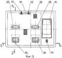
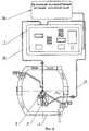
Изобретение поясняется чертежами. На фиг.1 представлена общая схема предлагаемого мобильного вакуумного аппаратного комплекса для иммобилизации локального участка миокарда; на фиг.2 - схема автономного вакуумного источника; на фиг.3 - переносной контейнер с автономным вакуумным источником, вид сверху (крышка снята); на фиг.4 - разрез А-А на фиг.3, на фиг.5 - разрез Б-Б на фиг.3; на фиг.6 - схема вакуумного комплекса с автономным источником питания. Изобретение представлено схематически без соблюдения пропорций между отдельными элементами.The invention is illustrated by drawings. Figure 1 presents the General scheme of the proposed mobile vacuum hardware complex for immobilization of the local area of the myocardium; figure 2 is a diagram of an autonomous vacuum source; figure 3 - portable container with a stand-alone vacuum source, top view (cover removed); figure 4 is a section aa in figure 3, figure 5 is a section bb in figure 3; 6 is a diagram of a vacuum complex with an autonomous power source. The invention is presented schematically without respecting the proportions between the individual elements.
Мобильный вакуумный аппаратный комплекс для временной иммобилизации локальных участков миокарда при операциях без остановки сердца содержит закрепленные на ранорасширителе 1 рамочный вакуумный стабилизатор 2 для иммобилизации локального участка миокарда и лепестковый вакуумный стабилизатор 3 положения сердца, присоски которых через ручной вентиль 4, влагоотделитель 5 и фильтрующее устройство 6 подключены к установленному в переносном контейнере 7 автономному вакуумному источнику, включающему в себя два вакуумных агрегата 8 и 9.The mobile vacuum apparatus complex for temporary immobilization of local areas of the myocardium during operations without cardiac arrest contains 1
Рамочный вакуумный стабилизатор 2 подключен к вакуумному агрегату 8, оснащенному основным 10 и дублирующим 11 вакуумными насосами. Вакуумные насосы 10 и 11 подключены к коллектору 12 через электрически управляемые нормально закрытые клапаны 13 и 14 регулирования уровня разрежения в коллекторе. Коллектор 12 соединен с атмосферой через электрически управляемый нормально закрытый клапан 15 сброса вакуума. К выходу коллектора подключен гибкий трубопровод 16, ведущий к рамочному вакуумному стабилизатору 2. Вакуумный агрегат 8 оснащен системой управления и контроля, имеющей датчик 17 уровня разрежения в коллекторе 12 и электронный блок 18 управления, оснащенный микропроцессором 19, дисплейным индикатором 20 режимов работы комплекса, клавиатурой 21 задания функциональных характеристик вакуумного агрегата 8, постоянным запоминающим устройством 22 и индикатором 23. Микропроцессор 19 через соответствующие интерфейсы и шины обмена данных связан с дисплейным индикатором 20, клавиатурой 21, датчиком 17 уровня разрежения в коллекторе 12. Управляющие сигналы микропроцессора через соответствующие интерфейсы передаются на электрически управляемые нормально закрытые клапаны 13 и 14 регулирования уровня разрежения в коллекторе и клапан 15 сброса вакуума в коллекторе, и на электроприводы 24 вакуумных насосов 10 и 11.The
Лепестковый вакуумный стабилизатор 3 подключен к вакуумному агрегату 9, оснащенному основным 25 и дублирующим 26 вакуумными насосами. Вакуумные насосы 25 и 26 подключены к коллектору 27 через электрически управляемые нормально закрытые клапаны 28 и 29 регулирования уровня разрежения в коллекторе. Коллектор 27 соединен с атмосферой через электрически управляемый нормально закрытый клапан 30 сброса вакуума. К выходу коллектора 27 подключен гибкий трубопровод 31, ведущий к лепестковому вакуумному стабилизатору 3. Вакуумный агрегат 9 оснащен системой управления и контроля, имеющей датчик 32 уровня разрежения в коллекторе 27 и электронный блок 33 управления, оснащенный микропроцессором 34, дисплейным индикатором 35 режимов работы комплекса, клавиатурой 36 задания функциональных характеристик вакуумного агрегата 9, постоянным запоминающим устройством 37 и индикатором 38. Микропроцессор 34 через соответствующие интерфейсы и шины обмена данных связан с дисплейным индикатором 35, клавиатурой 36, датчиком 32 уровня разрежения в коллекторе 27. Управляющие сигналы микропроцессора через соответствующие интерфейсы передаются на электрически управляемые нормально закрытые клапаны 28 и 29 регулирования уровня разрежения в коллекторе и клапан 30 сброса вакуума в коллекторе, и на электроприводы 39 вакуумных насосов 25 и 26.The
Указанный порядок подключения рамочного вакуумного стабилизатора 2 и лепесткового вакуумного стабилизатора 3 к вакуумным агрегатам 8 и 9 не является обязательным, и в зависимости от конкретной ситуации стабилизаторы 2 и 3 могут подключаться в ином порядке (например, как показано на фиг.6).The indicated procedure for connecting the
Электронные блоки 18 и 32 подключены к принтеру 40 (устройству регистрации функциональных характеристик комплекса во время операции).The
Каждый дисплейный индикатор 20 или 35 представляет собой плоский дисплей на жидких кристаллах, на экране которого отображается текстовая и числовая информация, характеризующая задаваемые или текущие характеристики вакуумных агрегатов 8 и 9 вакуумного аппаратного комплекса. Информация, представляемая на дисплейный индикатор, содержит дату и время запуска контролируемого вакуумного агрегата, номер работающего насоса, заданное и текущее разрежение (в кПа), текущее время работы.Each
Вакуумные агрегаты 8 и 9, электронные блоки 18 и 33 управления и принтер 40 смонтированы в переносном контейнере 7, имеющем лицевую панель 41. Верхняя поверхность лицевой панели 41 и пространство под ней поделены на три функциональные зоны.
В левой функциональной зоне в пространстве под лицевой панелью 41 размещены силовые узлы вакуумного агрегата 8, в том числе вакуумные насосы 10 и 11 с приводами 24 и органы их управления, на лицевой панели размещены клавиатура 21 задания функциональных характеристик вакуумного агрегата 8 и дисплейный индикатор 20, а на боковой стенке - ниппель 42 для гибкого трубопровода 16, ведущего к рамочному вакуумному стабилизатору 2.In the left functional area in the space under the
В центральной функциональной зоне в пространстве под лицевой панелью 41 размещены силовые узлы вакуумного агрегата 9, в том числе вакуумные насосы 25 и 26 с приводами 39 и органы их управления, на лицевой панели размещены клавиатура 36 задания функциональных характеристик вакуумного агрегата 9 и дисплейный индикатор 35, а на боковой стенке - ниппель 43 для гибкого трубопровода 31, ведущего к лепестковому вакуумному стабилизатору 3.In the central functional zone in the space under the
В правой функциональной зоне размещены принтер 40 и выключатель 44 электропитания.In the right functional area, a
Переносной контейнер 7 оснащен опорами 45, размещенными с его внешней стороны. С противоположной стороны стенки опоры 45 присоединены к силовым балкам 46, на которых закреплено шасси 47. Вакуумные насосы 10 и 11 вакуумного агрегата 8 закреплены на шасси 47 параллельно друг другу. Аналогичным образом на шасси 47 закреплены вакуумные насосы 25 и 26 вакуумного агрегата 9. Все остальные узлы вакуумных агрегатов 8 и 9 либо непосредственно закреплены на шасси 47, либо присоединены к нему через промежуточные крепежные элементы: стойки, кронштейны и т.п.The
Переносной контейнер выполнен со ступенчатой верхней панелью 41 с выступающим над боковыми полками 48 двухступенчатым центральным отсеком 49 и оснащен стойками 50, соединяющими указанные боковые полки с шасси 47. Принтер 40 размещен на лицевой панели нижней ступени 51 центрального отсека (третья функциональная зона). Первая и вторая функциональные зоны размещены на лицевой панели верхней ступени 52 центрального отсека над соответствующими вакуумными агрегатами. На лицевой панели верхней ступени 52 центрального отсека имеются вентиляционные решетки 53, например щелевые. Ниппели 42 и 43 размещены на задней стенке 54 центрального отсека в зонах, прилегающих к соответствующему вакуумному агрегату.The portable container is made with a stepped
Переносной контейнер имеет два колеса 55 и ручку для перемещения контейнера. Ручка для перемещения контейнера может быть любого типа и на чертеже не показана. Контейнер может иметь съемный шнур питания для подключения его к источнику питания. В качестве источника питания может выступать силовая электросеть больницы. Для передвижных комплексов целесообразно иметь автономный аккумуляторный источник электропитания, размещенный в дополнительном переносном контейнере 56, к которому подключается переносной контейнер 7 с автономным вакуумным источником, как это показано на фиг.6. Емкость источника питания должна быть достаточна для работы комплекса не менее 3 часов.The transportable container has two
В рабочем положении ранорасширитель 1 установлен на вскрытой грудной клетке пациента. Все оборудование вакуумного источника находится в переносном контейнере 7. Вес контейнера 7 минимален, так как все силовые нагрузки передаются непосредственно на шасси 47 и через балки 46 - на опоры 45. Тем самым стенка контейнера 7 освобождается от силовых нагрузок, что позволяет сделать ее с минимальной толщиной.In the working position, the
Хирург закрепляет на ранорасширителе 1 рамочный вакуумный стабилизатор 2 и лепестковый вакуумный стабилизатор 3. Точки крепления стабилизаторов 2 и 3 определяются хирургом непосредственно на месте. Стабилизаторы 2 и 3 подключаются к ниппелям 42 и 43 на задней стенке центрального отсека переносного контейнера. При подключении стабилизатора к ниппелю хирург настраивает соответствующий вакуумный агрегат на требуемый уровень разрежения, который может определяться хирургом непосредственно в ходе операции в зависимости от состояния сердца. При этом клавиатура для настройки вакуумного агрегата и дисплейный индикатор располагаются в той же функциональной зоне, что и ниппель, что облегчает работу хирурга, так как ему не нужно угадывать, с какой клавиатурой работать. Используя клавиатуру, хирург задает параметры работы вакуумного агрегата, которые высвечиваются на дисплейном индикаторе над клавиатурой, что дает возможность хирургу полностью контролировать настройку вакуумного агрегата на работу. Каждый вакуумный агрегат настраивается самостоятельно, и на дисплейных индикаторах постоянно высвечиваются характеристики обоих вакуумных агрегатов. Документальная регистрация характеристик вакуумных агрегатов производится принтером 40 в режиме поочередного опроса электронных блоков управления 18 и 33 вакуумных агрегатов.The surgeon secures a
Процедура настройки вакуумных агрегатов и проверки правильности их функционирования совпадает с процедурой, описанной в патенте Российской Федерации №2216284.The procedure for setting up vacuum units and checking the correctness of their operation coincides with the procedure described in the patent of the Russian Federation No. 2216284.
При проведении операции каждый стабилизатор настроен на свой оптимальный уровень разрежения, что снижает или полностью исключает травмирование миокарда при операции. При этом не имеет значения, для какого из стабилизаторов уровень разрежения должен быть выше, или оба стабилизатора работают при одинаковом уровне разрежения. Если в процессе операции откажет один из вакуумных насосов и произойдет изменение давления в коллекторе, микропроцессор 19 или 34 подключит к ресиверу дублирующий вакуумный насос и будет продолжать поддерживать заданное разрежение в коллекторе, используя дублирующий вакуумный насос. В ходе операции принтер 40 периодически распечатывает характеристики каждого вакуумного агрегата: номер работающего вакуумного насоса, уровень разрежения в коллекторе и текущее время операции.During the operation, each stabilizer is set to its optimal vacuum level, which reduces or completely eliminates myocardial injury during surgery. It does not matter for which of the stabilizers the vacuum level should be higher, or both stabilizers operate at the same vacuum level. If during the operation one of the vacuum pumps fails and the pressure in the manifold changes, the
Заявленный вакуумный аппаратный комплекс может быть изготовлен промышленным способом с использованием современных материалов, электронных компонентов и технологий. В частности, для комплектования данного комплекса можно использовать микропроцессор PIC 16F874-04/SP фирмы "Микрочип" США и матричный принтер CBM-910-40RF230-A фирмы CITIZEN. При реализации изобретения могут использоваться различные конструктивные исполнения отдельных узлов и блоков, отличающиеся от описанных в данной заявке и приведенных на чертежах, иллюстрирующих изобретение, без отхода от сути и рамок настоящего изобретения, определяемых объемом притязаний, изложенных в формуле изобретения.The claimed vacuum hardware complex can be manufactured industrially using modern materials, electronic components and technologies. In particular, for completing this complex, you can use the PIC 16F874-04 / SP microprocessor from Microchip USA and the CBM-910-40RF230-A matrix printer from CITIZEN. When implementing the invention, various designs of individual units and blocks can be used that differ from those described in this application and shown in the drawings illustrating the invention, without departing from the essence and scope of the present invention, determined by the scope of the claims set forth in the claims.
Claims (9)
Translated fromRussianPriority Applications (2)
| Application Number | Priority Date | Filing Date | Title |
|---|---|---|---|
| RU2005107635/14ARU2284161C1 (en) | 2005-03-21 | 2005-03-21 | Mobile vacuum hardware complex for temporary immobilizing local myocardium zones in doing operations without cardiac arrest |
| PCT/RU2005/000467WO2006101416A1 (en) | 2005-03-21 | 2005-09-16 | Mobile vacuum apparatus arrangement for temporarily immobilising a myocardium local areas operations without stopping a heart |
Applications Claiming Priority (1)
| Application Number | Priority Date | Filing Date | Title |
|---|---|---|---|
| RU2005107635/14ARU2284161C1 (en) | 2005-03-21 | 2005-03-21 | Mobile vacuum hardware complex for temporary immobilizing local myocardium zones in doing operations without cardiac arrest |
Publications (1)
| Publication Number | Publication Date |
|---|---|
| RU2284161C1true RU2284161C1 (en) | 2006-09-27 |
Family
ID=37024020
Family Applications (1)
| Application Number | Title | Priority Date | Filing Date |
|---|---|---|---|
| RU2005107635/14ARU2284161C1 (en) | 2005-03-21 | 2005-03-21 | Mobile vacuum hardware complex for temporary immobilizing local myocardium zones in doing operations without cardiac arrest |
Country Status (2)
| Country | Link |
|---|---|
| RU (1) | RU2284161C1 (en) |
| WO (1) | WO2006101416A1 (en) |
Citations (6)
| Publication number | Priority date | Publication date | Assignee | Title |
|---|---|---|---|---|
| RU2026640C1 (en)* | 1984-09-13 | 1995-01-20 | Адолий Яковлевич Кононов | Method for surgical treatment of ischemia |
| WO1999016367A1 (en)* | 1997-09-26 | 1999-04-08 | Alliance Medical Technologies, Inc. | Stabilizer |
| US6110187A (en)* | 1995-02-24 | 2000-08-29 | Heartport, Inc. | Device and method for minimizing heart displacements during a beating heart surgical procedure |
| US6139492A (en)* | 1994-08-31 | 2000-10-31 | Heartport, Inc. | Device and method for isolating a surgical site |
| US6334843B1 (en)* | 1995-09-20 | 2002-01-01 | Medtronic, Inc. | Method and apparatus for temporarily immobilizing a local area of tissue |
| RU2216284C1 (en)* | 2002-04-30 | 2003-11-20 | Акчурин Ренат Сулейманович | Vacuum apparatus complex for temporary immobilization of myocardium local areas in operations without cardiac arrest and device for immobilization of myocardium local area |
Family Cites Families (2)
| Publication number | Priority date | Publication date | Assignee | Title |
|---|---|---|---|---|
| BR9913759A (en)* | 1998-09-15 | 2001-06-12 | Medtronic Inc | System to temporarily immobilize an area of tissue, and system to stabilize tissue |
| US6447443B1 (en)* | 2001-01-13 | 2002-09-10 | Medtronic, Inc. | Method for organ positioning and stabilization |
- 2005
- 2005-03-21RURU2005107635/14Apatent/RU2284161C1/ennot_activeIP Right Cessation
- 2005-09-16WOPCT/RU2005/000467patent/WO2006101416A1/enactiveApplication Filing
Patent Citations (6)
| Publication number | Priority date | Publication date | Assignee | Title |
|---|---|---|---|---|
| RU2026640C1 (en)* | 1984-09-13 | 1995-01-20 | Адолий Яковлевич Кононов | Method for surgical treatment of ischemia |
| US6139492A (en)* | 1994-08-31 | 2000-10-31 | Heartport, Inc. | Device and method for isolating a surgical site |
| US6110187A (en)* | 1995-02-24 | 2000-08-29 | Heartport, Inc. | Device and method for minimizing heart displacements during a beating heart surgical procedure |
| US6334843B1 (en)* | 1995-09-20 | 2002-01-01 | Medtronic, Inc. | Method and apparatus for temporarily immobilizing a local area of tissue |
| WO1999016367A1 (en)* | 1997-09-26 | 1999-04-08 | Alliance Medical Technologies, Inc. | Stabilizer |
| RU2216284C1 (en)* | 2002-04-30 | 2003-11-20 | Акчурин Ренат Сулейманович | Vacuum apparatus complex for temporary immobilization of myocardium local areas in operations without cardiac arrest and device for immobilization of myocardium local area |
Also Published As
| Publication number | Publication date |
|---|---|
| WO2006101416A1 (en) | 2006-09-28 |
Similar Documents
| Publication | Publication Date | Title |
|---|---|---|
| US20220134121A1 (en) | External defibrillator | |
| US8033281B2 (en) | Modular transportable life support device | |
| WO2012037794A1 (en) | Field cabin for rapid minimally-invasive interventional treatment for gbh in heart and blood vessel | |
| US5779657A (en) | Nonstretchable wound cover and protector | |
| McSWAIN | Pneumatic trousers and the management of shock | |
| WO2009061662A1 (en) | Foldable, portable trauma treatment and monitoring patient platform | |
| CN105451813A (en) | Compact controller device for defibrillator | |
| RU2284161C1 (en) | Mobile vacuum hardware complex for temporary immobilizing local myocardium zones in doing operations without cardiac arrest | |
| WO2009061663A1 (en) | Lightweight portable trauma treatment and patient monitoring device | |
| CN102512249A (en) | Bone trauma auxiliary diagnosing treatment platform | |
| CN203328917U (en) | Novel movable hospital | |
| CN206979635U (en) | A kind of pelvic fixed belt | |
| CN109009471A (en) | Have both the medical supplies storage facilities for the treatment of prompt facility | |
| RU2216284C1 (en) | Vacuum apparatus complex for temporary immobilization of myocardium local areas in operations without cardiac arrest and device for immobilization of myocardium local area | |
| US12167907B2 (en) | Wireless system and methods for remote ischemic conditioning, external counterpulsation, other cuff-based therapies, and patient monitoring | |
| CN213045620U (en) | Heel forced induction shoe-pad and heel forced induction ankle socks | |
| JP2008104682A (en) | Blood purification treatment system | |
| RU58919U1 (en) | AUTONOMOUS COMPLEX FOR OPERATIONS ON THE OPEN WORKING HEART | |
| RU28972U1 (en) | Mobile medical vehicle (field hospital) | |
| CN201088768Y (en) | Thoracic drainage tube | |
| CN212090126U (en) | Surgical nursing protection device | |
| CN212234680U (en) | Intracardiac branch of academic or vocational study operation development device | |
| Lurin et al. | TEMPORARY COMPRESSION OF THE AORTA IN COMBAT SURGICAL TRAUMA | |
| Pinto et al. | Cardiac Surgery Equipment-Operation Principles and Maintenance Procedures | |
| CN204233370U (en) | The integration detection bed that a kind of obstetrics are special |
Legal Events
| Date | Code | Title | Description |
|---|---|---|---|
| MM4A | The patent is invalid due to non-payment of fees | Effective date:20100322 | |
| NF4A | Reinstatement of patent | Effective date:20110427 | |
| MM4A | The patent is invalid due to non-payment of fees | Effective date:20190322 |