RU2282551C2 - Trailer for trailer-train - Google Patents
Trailer for trailer-trainDownload PDFInfo
- Publication number
- RU2282551C2 RU2282551C2RU2003119459/11ARU2003119459ARU2282551C2RU 2282551 C2RU2282551 C2RU 2282551C2RU 2003119459/11 ARU2003119459/11 ARU 2003119459/11ARU 2003119459 ARU2003119459 ARU 2003119459ARU 2282551 C2RU2282551 C2RU 2282551C2
- Authority
- RU
- Russia
- Prior art keywords
- chassis
- main chassis
- additional
- trailer
- axis
- Prior art date
Links
- 239000012530fluidSubstances0.000claimsdescription16
- 230000002441reversible effectEffects0.000claimsdescription10
- 238000004891communicationMethods0.000claimsdescription3
- 230000013011matingEffects0.000claimsdescription3
- 238000006073displacement reactionMethods0.000claimsdescription2
- 239000002689soilSubstances0.000claimsdescription2
- 230000009897systematic effectEffects0.000claims1
- 230000000694effectsEffects0.000abstractdescription4
- 239000000126substanceSubstances0.000abstract1
- 238000004642transportation engineeringMethods0.000abstract1
- 238000000034methodMethods0.000description6
- 238000010276constructionMethods0.000description4
- 230000004048modificationEffects0.000description4
- 238000012986modificationMethods0.000description4
- 238000005096rolling processMethods0.000description4
- 230000000712assemblyEffects0.000description3
- 238000000429assemblyMethods0.000description3
- 238000000926separation methodMethods0.000description3
- 230000008901benefitEffects0.000description2
- 230000008859changeEffects0.000description2
- 230000036316preloadEffects0.000description2
- 230000009467reductionEffects0.000description2
- 230000004044responseEffects0.000description2
- 238000005299abrasionMethods0.000description1
- 230000009471actionEffects0.000description1
- 230000001154acute effectEffects0.000description1
- 239000003795chemical substances by applicationSubstances0.000description1
- 230000008602contractionEffects0.000description1
- 235000021438curryNutrition0.000description1
- 230000003111delayed effectEffects0.000description1
- 230000007717exclusionEffects0.000description1
- 239000000446fuelSubstances0.000description1
- 238000011900installation processMethods0.000description1
- 238000004519manufacturing processMethods0.000description1
- 239000000725suspensionSubstances0.000description1
Images


Classifications
- B—PERFORMING OPERATIONS; TRANSPORTING
- B62—LAND VEHICLES FOR TRAVELLING OTHERWISE THAN ON RAILS
- B62D—MOTOR VEHICLES; TRAILERS
- B62D13/00—Steering specially adapted for trailers
- B62D13/02—Steering specially adapted for trailers for centrally-pivoted axles
- B62D13/025—Steering specially adapted for trailers for centrally-pivoted axles the pivoted movement being initiated by the coupling means between tractor and trailer
Landscapes
- Engineering & Computer Science (AREA)
- Chemical & Material Sciences (AREA)
- Combustion & Propulsion (AREA)
- Transportation (AREA)
- Mechanical Engineering (AREA)
- Vehicle Body Suspensions (AREA)
- Testing Of Balance (AREA)
- Automobile Manufacture Line, Endless Track Vehicle, Trailer (AREA)
- Handcart (AREA)
- Body Structure For Vehicles (AREA)
- Automatic Cycles, And Cycles In General (AREA)
- Steering Controls (AREA)
Abstract
Description
Translated fromRussianНастоящее изобретение относится к автопоездам, имеющим тягач или трактор и один или несколько прицепов.The present invention relates to road trains having a tractor or tractor and one or more trailers.
Транспортное средство этого класса, которое можно часто видеть, представляет собой «полуприцеп», имеющий тягач с одним прицепом, при этом прицеп обычно длиннее тягача. Прицеп обычно имеет один, два или три неуправляемых моста вблизи заднего конца и поворотную площадку на переднем конце, которая сопрягается с взаимодействующим устройством (называемым прицепным устройством) на тягаче так, что на повороте прицеп может поворачиваться вокруг по существу вертикальной оси тягача.A vehicle of this class, which can often be seen, is a "semi-trailer" having a tractor with one trailer, and the trailer is usually longer than the tractor. A trailer typically has one, two, or three unmanaged bridges near the rear end and a pivot pad at the front end that mates with an interacting device (called a tow hitch) on the tractor so that the trailer can pivot around the substantially vertical axis of the tractor.
При использовании автопоездов этого типа возникает большое количество проблем. Одна из них связана с маневрированием. Например, по сравнению с более короткими транспортными средствами для поворотов необходима дорога значительной ширины, а требования к водительскому мастерству могут быть высокими, поскольку фиксированные колеса прицепа обычно «выходят из колеи тягача», то есть отказываются следовать по траектории, используемой колесами тягача. По меньшей мере на сравнительно малых скоростях колеса прицепа обычно прокладывают колею внутри траектории тягача. Эти проблемы могут быть особенно острыми на городских дорогах, когда поворот транспортного средства на одной полосе движения может происходить с заездом на другую полосу движения. Известно, что на высоких скоростях движение колес прицепа происходит за пределами траектории тягача. Однако большее практическое значение имеет проблема выхода из колеи тягача на сравнительно небольших скоростях, и много усилий было затрачено при попытках найти практические решения этой проблемы.When using road trains of this type, a large number of problems arise. One of them is associated with maneuvering. For example, in comparison with shorter vehicles, corners require a considerable width of the road, and driving requirements can be high, since the fixed wheels of the trailer usually “go off the track of the tractor,” that is, refuse to follow the path used by the wheels of the tractor. At least at relatively low speeds, the wheels of the trailer usually track inside the tractor’s path. These problems can be especially acute on city roads, when the turn of a vehicle in one lane can occur with a stop in another lane. It is known that at high speeds the movement of the trailer wheels occurs outside the tractor trajectory. However, of greater practical importance is the problem of getting out of the track of the tractor at relatively low speeds, and a lot of effort has been expended in trying to find practical solutions to this problem.
Дальнейшая проблема заключается в износе шин вследствие истирания или трения о поверхность дороги. Когда на прицепе установлены многочисленные параллельные мосты, как это общепринято, то невозможно, чтобы оси вращения колес прицепа сходились к центру окружности поворота прицепа, вследствие чего трение шин о поверхность дороги является неизбежным. Помимо чрезмерного износа шин трение приводит к повышенному расходу топлива и также может приводить к худшему торможению и к более слабому сцеплению шин с поверхностью дороги.A further problem is tire wear due to abrasion or friction on the road surface. When numerous parallel bridges are mounted on the trailer, as is customary, it is not possible for the axles of rotation of the wheels of the trailer to converge to the center of the circle of rotation of the trailer, as a result of which tire friction on the road surface is inevitable. In addition to excessive tire wear, friction leads to increased fuel consumption and can also lead to worse braking and weaker tire adhesion to the road surface.
Еще одна дополнительная проблема, связанная с полуприцепами, относится к маневренности при заднем ходе. Такому транспортному средству может быть трудно маневрировать, особенно в тесных кварталах жилых домов.Another additional problem associated with semitrailers relates to maneuverability in reverse. Such a vehicle can be difficult to maneuver, especially in cramped quarters of residential buildings.
Настоящее изобретение направлено на по меньшей мере частичное устранение проблем, изложенных выше. Для решения этих проблем делались другие попытки, и многие из них потерпели неудачу из-за возникновения дополнительной проблемы, а именно необходимости значительных модификаций тягача по сравнению со «стандартным» тягачом, используемым для обычных полуприцепов. Поскольку обычно необходимо, чтобы конкретный прицеп буксировался многими различными тягачами, то желательны устройства, применение которых не требует значительных модификаций тягача, и настоящим изобретением предоставляется такое устройство.The present invention is directed to at least partially eliminating the problems set forth above. Other attempts were made to solve these problems, and many of them failed due to an additional problem, namely the need for significant modifications of the tractor compared to the “standard” tractor used for conventional semi-trailers. Since it is usually necessary that a particular trailer be towed by many different tractors, devices whose use does not require significant modifications to the tractor are desirable, and such a device is provided by the present invention.
Следует отметить, что проблема выхода прицепа из колеи тягача возникает и тогда, когда автопоезд имеет несколько прицепов позади тягача. Изобретение, раскрытое ниже, в некоторых воплощениях также применимо к таким автопоездам. Тягачи с двумя полуприцепами часто используются на строительных площадках крупных городов, и известны транспортные средства, имеющие три или более прицепов, хотя вследствие ограниченной маневренности их применение обычно ограничено дорогами вне крупных городов и в условиях бездорожья.It should be noted that the problem of the trailer getting out of the track of the tractor also occurs when the road train has several trailers behind the tractor. The invention disclosed below, in some embodiments, is also applicable to such road trains. Tractors with two semi-trailers are often used on construction sites of large cities, and vehicles with three or more trailers are known, although due to limited maneuverability their use is usually limited to roads outside large cities and in off-road conditions.
Для решения или частичного решения проблем, близко связанных с движением по одной колее и с трением шин о поверхность дороги, предлагались разнообразные способы, но они имели множество недостатков, препятствующих их широкому распространению для обычных тягачей с полуприцепами.A variety of methods have been proposed to solve or partially solve problems that are closely related to driving along one track and friction of tires on the road surface, but they had many drawbacks that prevented their widespread use for conventional tractors with semitrailers.
Один способ уменьшения трения шин на прицепах о поверхность дороги, но который весьма малопригоден для улучшения движения по одной колее, заключается в снабжении нескольких колесно-мостовых узлов закрепленными (неуправляемыми) колесами, но в целом свободно поворачивающимися вокруг вертикальной оси, расположенной по направлению движения перед мостом, в результате чего колеса становятся самоориентирующимися. Например, см. патентный документ PCT/AU 94/00743 (Sibbald) и патент Австралии №664919 (Becker and Ennor). Для обеспечения возможности движения задним ходом конструкции этого класса должны иметь определенные средства для фиксации колесно-мостовых узлов в выровненном по прямой линии положении или для смещения вертикальной оси позади моста. Узел самоориентирующихся колес не нашел широкого практического применения.One way to reduce the friction of tires on trailers on the road surface, but which is very unsuitable for improving movement on one track, is to provide several wheel-axle units with fixed (uncontrolled) wheels, but generally freely rotating around a vertical axis located in the direction of travel in front of bridge, causing the wheels to become self-orientating. For example, see Patent Document PCT / AU 94/00743 (Sibbald) and Australian Patent No. 664919 (Becker and Ennor). To enable reverse gear, structures of this class must have certain means for fixing wheel-axle assemblies in a position aligned in a straight line or for displacing the vertical axis behind the bridge. The self-aligning wheel assembly has not found wide practical application.
Проблему уменьшения выхода прицепов из колеи тягача чаще всего решают путем создания конструкций, в которых по меньшей мере некоторые из колес «управляются» во время поворота в направлении, противоположном направлению управления тягача. То есть, если тягач начинает поворачивать вправо, некоторые колеса вблизи задней части прицепа ориентируются для выполнения смещения задней части прицепа влево, то есть наружу от направления поворота. Если степень такой ориентации выбрана соответствующим образом, задняя часть прицепа может вынужденно следовать в значительной степени по траектории, используемой тягачом. Многие из этих конструкций также снижают значимость проблемы трения шин о поверхность дороги, хотя степень снижения имеет широкий разброс среди различных предложений.The problem of reducing the exit of trailers from the track of the tractor is most often solved by creating designs in which at least some of the wheels are “controlled” during rotation in the direction opposite to the direction of control of the tractor. That is, if the tractor starts to turn to the right, some wheels near the rear of the trailer are oriented to shift the rear of the trailer to the left, that is, out of the direction of rotation. If the degree of this orientation is selected appropriately, the rear of the trailer may have to follow to a large extent along the path used by the tractor. Many of these designs also reduce the significance of the problem of tire friction on the road surface, although the degree of reduction has wide variation among various proposals.
В некоторых или в части этих усовершенствованных устройств осуществляется активная ориентация колес прицепа вследствие поворота тягача относительно прицепа или вследствие управления передними колесами тягача. Для использования этих устройств обычно необходим тягач, существенно отличающийся от обычного тягача. Эти устройства весьма разнообразны, от очень простых механических устройств, например, описанных в патенте США №3533644 (Humes), до более сложных устройств с механическим и/или гидравлическим приводом, таких, как устройство, описанное в патенте США №4982976 (Kramer).In some or part of these improved devices, the wheels of the trailer are actively oriented due to the rotation of the tractor relative to the trailer or due to the control of the front wheels of the tractor. To use these devices, a tractor is usually required, which differs significantly from a conventional tractor. These devices are very diverse, from very simple mechanical devices, such as those described in US Pat. No. 3,533,644 (Humes), to more complex devices with mechanical and / or hydraulic drives, such as the device described in US Pat. No. 4,982,976 (Kramer).
В устройствах другого класса для обеспечения движения по одной колее использовано стремление колес прицепа продолжать движение вперед, когда на повороте передняя часть прицепа смещается вбок. Являющееся результатом этого различие между первоначальной траекторией этих колес и новой траекторией колес прицепа характеризует входные данные, которые могут быть использованы для ориентации колес прицепа для коррекции движения относительно траектории тягача. В патенте США №3899188 (Curry) описано такое устройство с мостовым узлом, в котором колеса не управляются (то есть в котором направление колес относительно моста не может изменяться), на задней части дополнительного шасси и с колесно-мостовым узлом, имеющим индивидуально управляемые колеса, на передней части дополнительного шасси. В патенте США №5246242 (Penzotti) описан вариант, имеющий два закрепленных мостовых узла на дополнительном шасси. Принцип действия этих обоих устройств основан на относительном перемещении основного шасси и дополнительного шасси прицепа, возникающего при повороте, и при этом не требуется каким-либо образом модифицировать обычный тягач. Это является преимуществом. В обоих устройствах для осуществления движения задним ходом требуется средство для фиксации дополнительного шасси на основном шасси прицепа в положении выравнивания по прямой линии. В патентном документе PCT/GB 97/02008 (Mitchell) описано сравнительно сложное устройство с двумя рядами индивидуально управляемых колес и с закрепленным колесно-мостовым узлом на дополнительном шасси, имеющее средство для обеспечения различного и выбираемого управления вследствие движения передним или задним ходом.In devices of another class, to ensure movement along one track, the trailer’s wheels continue to move forward when the front of the trailer is shifted to the side when cornering. The resulting difference between the initial trajectory of these wheels and the new trajectory of the trailer wheels characterizes the input data that can be used to orient the trailer wheels to correct movement relative to the trajectory of the tractor. US Pat. No. 3,899,188 (Curry) describes such a device with a bridge assembly in which the wheels cannot be controlled (that is, in which the direction of the wheels relative to the bridge cannot be changed), at the rear of the additional chassis and with a wheel-bridge assembly having individually controlled wheels on the front of the optional chassis. US Pat. No. 5,246,242 (Penzotti) describes an embodiment having two fixed bridge assemblies on an additional chassis. The principle of operation of both of these devices is based on the relative movement of the main chassis and the additional chassis of the trailer that occurs when turning, and it does not need to be modified in any way by a conventional tractor. This is an advantage. In both devices, reverse gear is required to fix the additional chassis on the main chassis of the trailer in a straight line alignment position. PCT / GB 97/02008 (Mitchell) describes a relatively complex device with two rows of individually controlled wheels and a fixed wheel-axle assembly on an additional chassis, having means for providing different and selectable controls due to forward or reverse movement.
В соответствии с настоящим изобретением разработан прицеп для использования в качестве части автопоезда, содержащий основное шасси, выполненное с возможностью шарнирного соединения с колесной частью автомобиля непосредственно перед прицепом с возможностью поворота колесной части относительно основного шасси вокруг по существу вертикальной первой оси на основном шасси, дополнительное шасси, имеющее множество пар сцепляющихся с грунтом колес, установленных на нем на расстоянии друг от друга в продольном направлении, и соединенное с основным шасси с возможностью свободного поворота вокруг по существу вертикальной второй оси на основном шасси стопорное средство, приспособленное задавать максимальный угол свободного поворота дополнительного шасси от положения выравнивания в продольном направлении относительно основного шасси, зависящий от позиционирования стопорного средства относительно основного шасси. Согласно изобретению прицеп имеет средство для автоматического позиционирования стопорного средства относительно основного шасси при повороте колесной части вокруг первой оси так, что максимальный угол изменяется в соответствии с позиционированием стопорного средства, и управляющее средство, реагирующее на относительный поворот дополнительного шасси и основного шасси вокруг второй оси, для управления по меньшей мере двумя указанными парами колес относительно дополнительного шасси для выравнивания в продольном направлении дополнительного шасси относительно основного шасси, при этом каждая указанная пара управляемых колес установлена на неподвижном мостовом узле, шарнирно соединенном с дополнительным шасси, и выполнена с возможностью управления посредством поворота мостового узла вокруг по существу вертикальной третьей оси на дополнительном шасси, при этом оси вращения каждой пары управляемых колес сходятся друг к другу на стороне дополнительного шасси при повороте прицепа.In accordance with the present invention, there is provided a trailer for use as part of a road train, comprising a main chassis configured to swivel with the wheel part of the vehicle immediately in front of the trailer with the ability to rotate the wheel part relative to the main chassis around a substantially vertical first axis on the main chassis, an additional chassis having many pairs of wheels mating with the soil mounted on it at a distance from each other in the longitudinal direction, and connected to main chassis with the possibility of free rotation around a substantially vertical second axis on the main chassis locking means adapted to set the maximum angle of free rotation of the additional chassis from the alignment position in the longitudinal direction relative to the main chassis, depending on the position of the locking means relative to the main chassis. According to the invention, the trailer has means for automatically positioning the locking means relative to the main chassis when the wheel part is rotated around the first axis so that the maximum angle changes in accordance with the positioning of the locking means, and control means responsive to the relative rotation of the additional chassis and the main chassis around the second axis, to control at least two of these pairs of wheels relative to the additional chassis for alignment in the longitudinal direction of the additional the chassis relative to the main chassis, with each specified pair of steered wheels mounted on a fixed axle unit pivotally connected to the additional chassis, and made with the possibility of control by rotating the bridge unit around a substantially vertical third axis on the additional chassis, while the axis of rotation of each pair steered wheels converge to each other on the side of the additional chassis when turning the trailer.
Управляющее средство может включать первый соединительный элемент, соединяющий мостовой узел и основное шасси или часть, прикрепленную к основному шасси.The control means may include a first connecting element connecting the bridge assembly and the main chassis or a part attached to the main chassis.
При использовании прицепа на криволинейном пути движения угол поворота дополнительного шасси вокруг второй оси и удаления от положения выравнивания в продольном направлении относительно основного шасси может представлять собой максимальный угол.When using a trailer on a curved path, the angle of rotation of the additional chassis around the second axis and the distance from the alignment position in the longitudinal direction relative to the main chassis can be the maximum angle.
Прицеп может дополнительно содержать вилку, установленную на основном шасси и соприкасающуюся со стопорным средством, и соединительное средство для соединения вилки с дополнительным шасси, выполненное с возможностью перемещения на основном шасси при повороте дополнительного шасси вокруг второй оси. Вилка может быть установлена с возможностью перемещения на основном шасси в по существу продольном направлении и имеет поверхность скольжения, проходящую в по существу поперечном направлении относительно основного шасси, стопорное средство имеет ползун, установленный на основном шасси с возможностью поворота вокруг первой оси согласованно с колесной частью, поворотной вокруг первой оси, а поверхность скольжения соприкасается с ползуном.The trailer may further comprise a fork mounted on the main chassis and in contact with the locking means, and connecting means for connecting the fork to the additional chassis, made with the possibility of movement on the main chassis when the additional chassis is rotated around the second axis. The fork can be mounted to move on the main chassis in a substantially longitudinal direction and has a sliding surface extending in a substantially transverse direction relative to the main chassis, the locking means has a slider mounted on the main chassis to rotate around the first axle in accordance with the wheel part, turning around the first axis, and the sliding surface is in contact with the slider.
Прицеп может содержать две указанные вилки и два указанных соединительных средства, каждое из которых соединено с соответствующей вилкой, причем при выравнивании дополнительного шасси относительно основного шасси, для прямолинейного движения вперед, ползун расположен поперек и по существу на середине основного шасси, а соответствующие поверхности скольжения обеих вилок касаются ползуна, при этом соединительные средства, вилки и дополнительное шасси размещены таким образом, что, когда одна вилка перемещается вперед, другая вилка перемещается назад.The trailer may contain two of these forks and two of these connecting means, each of which is connected to a corresponding fork, and when aligning the additional chassis relative to the main chassis, for a straight forward movement, the slider is located across and essentially in the middle of the main chassis, and the corresponding sliding surfaces of both the forks touch the slider, while the connecting means, the forks and the additional chassis are positioned so that when one fork moves forward, the other eschaetsya ago.
Каждое соединительное средство может содержать второй соединительный элемент, шарнирно соединенный с вилкой и с дополнительным шасси.Each connecting means may comprise a second connecting element pivotally connected to a fork and to an additional chassis.
Каждая вилка может содержать упругое средство, выполненное с возможностью смещения вследствие контактного усилия между стопорным средством и вилкой.Each fork may include resilient means configured to bias due to the contact force between the locking means and the fork.
Каждое соединительное средство может содержать упругое средство, выполненное с возможностью смещения вследствие усилия, переданного соединительным средством к дополнительному шасси или от него.Each connecting means may comprise resilient means adapted to be biased due to the force transmitted by the connecting means to or from the additional chassis.
Прицеп может дополнительно содержать элемент, выполненный с возможностью перемещения вследствие поворота дополнительного шасси вокруг второй оси, и передающее перемещение средство, обеспечивающее перемещение следящего средства при перемещении указанного элемента, при этом соответствующее перемещение следящего средства ограничено стопорным средством. Передающее перемещение средство может содержать первый и второй гидравлические приводы, функционально соединенные посредством трубопроводов рабочей жидкости так, что приведение в действие указанного первого привода при перемещении указанного элемента создает посредством второго привода соответствующее перемещение следящего средства.The trailer may further comprise an element configured to move due to the rotation of the additional chassis around the second axis, and transferring the means for moving the tracking means when moving the specified element, while the corresponding movement of the tracking means is limited by the locking means. The transferring means may comprise first and second hydraulic actuators operatively connected by means of pipelines of the working fluid such that the actuation of said first drive when moving said element creates a corresponding movement of the follower means through the second drive.
Прицеп может дополнительно содержать резервуар, имеющий внутреннее пространство, сообщенное с трубопроводом рабочей жидкости, соединяющим указанные гидравлические приводы, и средство, с помощью которого объем указанного пространства увеличивается при повышении давления рабочей жидкости в указанном пространстве.The trailer may further comprise a reservoir having an internal space in communication with a working fluid pipeline connecting said hydraulic actuators, and means by which the volume of said space increases with increasing pressure of the working fluid in said space.
Прицеп может дополнительно содержать удлиненный телескопический соединительный элемент, имеющий заданную минимальную длину при его полностью вдвинутом положении и при этом положении вызывающий перемещение указанного элемента при повороте дополнительного шасси в конкретном направлении.The trailer may further comprise an elongated telescopic connecting element having a predetermined minimum length when it is fully retracted and at this position causing the indicated element to move when the additional chassis is rotated in a specific direction.
Соединительный элемент может быть одним из двух телескопических соединительных элементов, соответственно предназначенных для перемещения указанного элемента при повороте дополнительного шасси в противоположных, первом и втором направлениях, при этом, когда один соединительный элемент вызывает перемещение указанного элемента, длина другого соединительного элемента телескопически увеличивается.The connecting element can be one of two telescopic connecting elements, respectively, designed to move the specified element when rotating the additional chassis in the opposite, first and second directions, while when one connecting element causes the movement of the specified element, the length of the other connecting element is telescopically increased.
Стопорное средство может содержать кулачок, расположенный на основном шасси с возможностью поворота вокруг первой оси и выполненный с возможностью функциональной связи с колесной частью.The locking means may include a cam located on the main chassis with the possibility of rotation around the first axis and made with the possibility of functional connection with the wheel part.
Прицеп может содержать дополнительное стопорное средство для ограничения фиксированного максимального значения угла поворота дополнительного шасси вокруг второй оси и удаления от положения выравнивания относительно основного шасси.The trailer may contain additional locking means for limiting a fixed maximum value of the angle of rotation of the additional chassis around the second axis and moving away from the alignment position relative to the main chassis.
Прицеп может содержать первое фиксирующее средство, приспособленное для удержания дополнительного шасси и основного шасси выровненными в продольном направлении, когда дополнительное шасси выровнено в продольном направлении по отношению к основному шасси и любое угловое отклонение от выравнивания в продольном направлении колесной части и основного шасси меньше заданного значения. Первое фиксирующее средство имеет выбранный пользователем режим работы, при котором дополнительное шасси удерживается выровненным в продольном направлении относительно основного шасси до достижения заданного значения углового отклонения от выравнивания в продольном направлении колесной части и основного шасси.The trailer may comprise first locking means adapted to keep the auxiliary chassis and main chassis aligned in the longitudinal direction when the auxiliary chassis is longitudinally aligned with the main chassis and any angular deviation from the longitudinal alignment of the wheel part and the main chassis is less than a predetermined value. The first locking means has a user-selected mode of operation in which the auxiliary chassis is kept aligned longitudinally relative to the main chassis until a predetermined value of the angular deviation from alignment in the longitudinal direction of the wheel part and the main chassis is reached.
Прицеп может содержать второе фиксирующее средство, которое при включении заднего хода автопоезда фиксирует дополнительное шасси и основное шасси при таком относительном угловом отклонении вокруг второй оси, которое существует при включении заднего хода.The trailer may contain a second locking means, which when turning on the reverse of the road train, fixes the additional chassis and the main chassis at such a relative angular deviation around the second axis that exists when turning on the reverse.
Согласно изобретению создан автопоезд, содержащий вышеописанный прицеп.According to the invention, a road train is created comprising the above trailer.
Ниже изобретение будет описано более подробно со ссылками на предпочтительные варианты осуществления, хотя и без всякого ограничения объема изобретения. Будут делаться ссылки на чертежи, на которых:Below the invention will be described in more detail with reference to preferred embodiments, although without limiting the scope of the invention. Reference will be made to the drawings, in which:
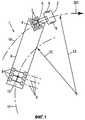
фиг.1 - схематичный вид в плане тягача с известным полуприцепом;figure 1 is a schematic plan view of a tractor with a known semi-trailer;
фиг.2 - схематичный вид в плане модифицированного тягача с полуприцепом;figure 2 is a schematic plan view of a modified tractor with a semi-trailer;
фиг.3 - схематичный вид в плане тягача с полуприцепом согласно изобретению;figure 3 is a schematic plan view of a tractor with a semi-trailer according to the invention;
фиг.4 - схематичный вид в плане еще одного тягача с полуприцепом согласно изобретению;4 is a schematic plan view of another tractor with a semi-trailer according to the invention;
фиг.5 - схематичный вид в плане транспортного средства, показанного на фиг.3, в конфигурации прямолинейного движения вперед;5 is a schematic plan view of the vehicle of FIG. 3 in a straight forward configuration;
фиг.6 - схематичный частичный вид в плане транспортного средства, показанного на фиг.5, в конфигурации поворота;FIG. 6 is a schematic partial plan view of the vehicle of FIG. 5 in a rotation configuration;
фиг.7 - разрез узла транспортного средства, показанного на фиг.6;Fig.7 is a section of the node of the vehicle shown in Fig.6;
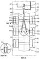
фиг.8 - схематичный частичный вид в направлении стрелки 350 на фиг.6;FIG. 8 is a schematic partial view in the direction of
фиг.9 - схематичный частичный вид в плане транспортного средства, показанного на фиг.3;Fig.9 is a schematic partial view in plan of the vehicle shown in Fig.3;
фиг.10 - схематичный частичный вид в плане транспортного средства, показанного на фиг.4;figure 10 is a schematic partial view in plan of the vehicle shown in figure 4;
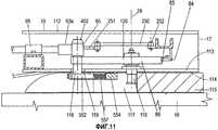
фиг.11 - местный разрез транспортного средства, показанного на фиг.6, выполненного по линии В-В;11 is a local section of the vehicle shown in Fig.6, made along the line BB;
фиг.12 - вид в перспективе с частичным пространственным разделением деталей узла транспортного средства, показанного на фиг.3;12 is a perspective view with partial spatial separation of the parts of the vehicle assembly shown in FIG. 3;
фиг.13 - схематичный частичный вид в плане транспортного средства, показанного на фиг.3, с альтернативным регулировочным стопорным средством согласно изобретению, при этом на фиг.13 один участок чертежа представлен в виде увеличенного изображения узла «А»;FIG. 13 is a schematic partial plan view of the vehicle of FIG. 3 with an alternative adjusting locking means according to the invention, wherein in FIG. 13 one section of the drawing is shown as an enlarged image of the assembly “A”;
фиг.14 - схематичный частичный вид в плане транспортного средства, показанного на фиг.3, с альтернативным регулировочным стопорным средством согласно изобретению;FIG. 14 is a schematic partial plan view of the vehicle of FIG. 3 with an alternative adjusting locking means according to the invention;
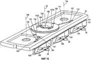
фиг.15 - вид в перспективе дополнительного шасси, предназначенного для использования в изобретении;15 is a perspective view of an additional chassis for use in the invention;
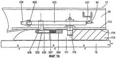
фиг.16 - местный разрез прицепа транспортного средства, показанного на фиг.3, сделанный по продольной центральной линии, снабженного альтернативным регулировочным стопорным средством согласно изобретению.FIG. 16 is a partial cross-sectional view of the vehicle trailer of FIG. 3 taken along a longitudinal center line provided with an alternative adjusting locking means according to the invention.
В нижеследующем описании рассмотрена основная изобретательская идея реализации регулировочного стопорного средства, применяемого для автоматического управления дополнительным шасси на прицепе, сначала в общих чертах, а затем со ссылками на два детализированных варианта осуществления. Далее описаны некоторые фиксирующие средства. После этого описана особенно предпочтительная форма осуществления дополнительного шасси, имеющего индивидуально управляемые мостовые узлы. Они применимы с любым вариантом осуществления регулировочного стопорного средства. В заключение описана новая конструкция прицепного устройства тягача, предназначенного для обеспечения соединения прицепа согласно изобретению с тягачом.In the following description, the main inventive idea of the implementation of the adjusting locking means used to automatically control the additional chassis on the trailer is discussed, first in general terms and then with reference to two detailed embodiments. The following describes some locking means. After this, a particularly preferred embodiment of an additional chassis having individually controlled bridge assemblies is described. They are applicable with any embodiment of the adjusting locking means. In conclusion, a new construction of a towing device of a tractor is described which is intended to provide a connection of the trailer according to the invention with a tractor.
На фиг.1 показан схематичный вид в плане автопоезда 1 типа «полуприцепа», имеющего тягач 2 и прицеп 3, шарнирно соединенные друг с другом в точке 4 вращения так, что тягач и прицеп могут поворачиваться относительно друг друга вокруг вертикальной оси 5. Транспортные средства, такие как автопоезд 1, хорошо известны из области техники, к которой относится изобретение. Тягач 2 и прицеп 3 показаны только в общих чертах, при этом механические детали опущены. Тягач 2 имеет пару управляемых колес 6 и две пары приводных, сцепляющихся с грунтом колес 7, хотя также известно использование другого числа приводных колес. Вблизи заднего конца прицеп 3 имеет три пары неприводных, сцепляющихся с грунтом колес, которые выполнены неуправляемыми. А именно, их оси 9 вращения закреплены по существу поперек длины прицепа 3. Эта конструкция является хорошо известной и обычной в области техники, к которой относится изобретение. Обычно также используют полуприцепы, которые имеют две пары или даже одну пару задних колес вместо трех пар 8.Figure 1 shows a schematic plan view of a
Транспортное средство 1, показанное на фиг.1, совершает поворот наряду с перемещением вперед. Стрелка 201 указывает направление движения. Точка 10 вблизи колес 8 перемещается по криволинейной траектории 11, радиус 12 которой меньше радиуса 13 траектории 14, описываемой точкой 4 вращения. Это явление наблюдается на практике по меньшей мере на небольших и средних скоростях и представляет собой форму «выхода прицепа из колеи тягача», чаще всего наблюдаемого на практике. Не считая возникающих трудностей при маневрировании, это приводит к трению о поверхность дороги по меньшей мере некоторых (а обычно всех) колес 8, поскольку они одновременно катятся и проскальзывают в сторону.The
На фиг.2 также схематично показан вид в плане транспортного средства 15, которое аналогично транспортному средству 1. Транспортное средство 15 имеет тягач 16 и прицеп 17. Прицеп 17 включает в себя основное шасси 18, прикрепленное к тягачу 16 с возможностью относительного поворота вокруг вертикальной оси 19. Основное шасси 18 также шарнирно закреплено с возможностью относительного поворота вокруг вертикальной оси 23 на дополнительном шасси 20, на котором в свою очередь установлены три пары колес 21. Колеса 21 являются неуправляемыми по отношению к дополнительному шасси 20, при этом их оси 22 поворота расположены поперек дополнительного шасси 20.2 also schematically shows a plan view of a
Если предположить, что дополнительное шасси 20 совершенно свободно поворачивается вокруг оси 23, и предположить далее, что транспортное средство 15 сначала движется вперед по прямой линии, при этом основное шасси 18, дополнительное шасси 20 и тягач 16 выровнены в продольном направлении, то есть продольные оси 24, 25 и 28 соответственно расположены на одной прямой. На фиг.2 показана ситуация вскоре после того, как тягач 16 транспортного средства 15 начал поворот вправо от первоначального прямолинейного направления вперед, указанного стрелкой 202. Поскольку относительный поворот основного шасси 18 и дополнительного шасси 20 вокруг оси 23 не ограничен, дополнительное шасси 20 продолжает стремиться в направлении 202, вследствие чего угол 26 между осями 24 и 25 возрастает по мере того, как транспортное средство 15 перемещается вперед. При отсутствии всякого ограничения угол 26 будет возрастать до большого значения, при котором начнется непредсказуемое и неконтролируемое поведение транспортного средства. Однако можно утверждать, что на начальной стадии поворота, показанной на фиг.2, прицеп 17 не выйдет внутрь из колеи тягача так, как это показано на фиг.1 для прицепа 3. В противоположность этому прицеп 17 перемещается к положению наружной траектории 27 оси 19 тягача.If we assume that the
Конструкция, показанная на фиг.2, является неустойчивой и непрактичной. Однако, если предположить, что поворот дополнительного шасси 20 транспортного средства 15 вокруг оси 23 ограничен таким образом, что угол 26 после достижения выбранного максимального значения 26' больше возрастать не может. Было обнаружено, что в этом случае ось 23 поворота следует по траектории, которая является промежуточной между двумя ситуациями, показанными на фиг.1 и 2. Для заданной траектории 27 тягача удовлетворяющий требованиям угол 26' может быть выбран так, чтобы при осуществлении поворота ось 23 поворота следовала бы по существу по той же самой траектории. То есть по существу не будет такого выхода прицепа из колеи тягача, который показан на фиг.1 и 2. На фиг.3 показана эта ситуация.The design shown in FIG. 2 is unstable and impractical. However, if we assume that the rotation of the
Как показано на фиг.3, значение угла 26', при котором получается точное движение по одной колее при осуществлении плавного поворота, зависит от радиуса траектории 27 тягача, который сам является переменным, выбираемым водителем транспортного средства 15. Поэтому в изобретении предусматривается, что угол 26' задается регулировочным стопорным средством (предпочтительные варианты осуществления которого будут подробно описаны ниже), выполненным таким образом, что угол 26' изменяется в соответствии с крутизной поворота. Во время поворота дополнительное шасси 20 поворачивается вокруг оси 23 описанным выше способом, стремясь к прямолинейной траектории до тех пор, пока угол 26 не достигнет значения 26', заданного стопорным средством.As shown in figure 3, the value of the angle 26 ', at which the exact movement along one track is obtained during a smooth turn, depends on the radius of the
В конструкции, показанной на фиг.3, некоторое трение колес 21 о поверхность дороги неизбежно, хотя и меньшее, чем в известном транспортном средстве, таком как транспортное средство 1, поскольку качение колес 21 по прямолинейной траектории ограничено и в случае трех параллельных осей 22 вращения качение без скольжения невозможно по любой криволинейной траектории. Обнаружено, что в ситуации, показанной на фиг.3, эффект трения колес о поверхность дороги обусловлен тем, что существует крутящий момент, приложенный к дополнительному шасси 20 в направлении, показанном стрелкой 303, который способствует увеличению угла 26.In the design shown in FIG. 3, some friction of the
Трение колес о поверхность дороги во время поворота можно дополнительно снизить путем комбинации описанного выше изобретения с дополнительным шасси другого типа, которое ниже описано в общих чертах и подробно. Это дополнительное шасси иного типа можно также использовать с другими регулировочными конструкциями тягача, и независимо от изобретения, описанного выше, оно само по себе является изобретением.The friction of the wheels on the road surface during a turn can be further reduced by combining the invention described above with an additional chassis of a different type, which is described below in general and in detail. This additional chassis of a different type can also be used with other adjusting structures of the tractor, and regardless of the invention described above, it is an invention in itself.
На фиг.4 показан автопоезд 29 с полуприцепом, содержащий иное дополнительное шасси 33 и имеющий тягач 30 и прицеп 31. Прицеп 31 имеет основное шасси 32, шарнирно соединенное с дополнительным шасси 33 с возможностью относительного поворота вокруг по существу вертикальной оси 349 на основном шасси 32. На дополнительном шасси 33 установлены три неприводных моста 34, 35 и 36. К мостам прикреплены сцепляющиеся с грунтом колесные пары 37, 38 и 39 соответственно, которые имеют оси 40, 41 и 42 вращения соответственно (хотя на фиг.4 показаны три пары колес, на самом деле при необходимости можно использовать две или четыре пары). Мост 35 установлен на дополнительном шасси 33 без возможности управления, то есть так, что ось вращения 41 колес 38 расположена поперек дополнительного шасси 33. Однако мосты 34 и 36 прикреплены к дополнительному шасси 33 шарнирно, вследствие чего колесные пары 37 и 39 являются управляемыми по отношению к дополнительному шасси, что показано на фиг.4. Предусмотрено управляющее средство (описанное подробно ниже), посредством которого в ответ на поворот дополнительного шасси 33 вокруг оси 349 с удалением от положения выравнивания в продольном направлении по отношению к основному шасси 32 мосты 34 и 36 поворачиваются вокруг центра так, что их оси 40 и 42 вращения сходятся к оси 41 вращения на одной стороне дополнительного шасси 33. Конкретно, оси 40, 41 и 42 вращения сходятся друг к другу на внутренней стороне осуществляемого поворота. В идеализированной ситуации, показанной на фиг.4, оси 40, 41 и 42 вращения сходятся с осями 43, 44 и 45 вращения колес 46, 47 и 48 тягача (ось 45 вращения представляет собой среднюю ось вращения приводных колес 48 тягача 30). Однако на практике для движения по одной колее не нужна идеальная сходимость осей вращения с 40 по 42 и с 43 по 45, показанных на фиг.4, и трение колес о поверхность дороги существенно снижается по сравнению с известными транспортными средствами, такими как транспортные средства 1 и 15.Figure 4 shows a
На фиг.4 угол 159' между продольными осями 160 и 161 основного шасси 32 и дополнительного шасси 33 соответствует углу 26' на фиг.3.In figure 4, the angle 159 'between the
Путем использования иного дополнительного шасси 33, а не дополнительного шасси 20, в комбинации с регулировочным стопорным средством, упомянутым выше (и описанным ниже), можно получить большее снижение трения колес о поверхность дороги наряду с более точным движением по одной колее, которое может обеспечить регулировочное стопорное средство. Это происходит потому, что в противоположность комбинированному качению и скольжению чистое качение становится более достижимым.By using a different
Регулировочное стопорное средство будет описано при использовании в качестве примера транспортного средства 15, показанного на фиг.3. Однако понятно, что транспортное средство 29, показанное на фиг.4, с управляемыми мостами на дополнительном шасси 33 можно в равной степени использовать в качестве основы для описания, а регулировочное стопорное средство в равной степени применимо к таким транспортным средствам, как транспортное средство 29. Будут описаны несколько вариантов осуществления регулировочного стопорного средства.An adjusting locking means will be described when using the
(а) Полностью механическое регулировочное стопорное средство(a) Fully mechanical adjusting locking means
На фиг.5 показан схематичный вид в плане транспортного средства 15 с тягачом 16, основным шасси 18 и дополнительным шасси 20, выровненными в продольном направлении, как при прямолинейном движении вперед. Транспортное средство 15 показано снабженным полностью механическим регулировочным стопорным средством, в целом обозначенным как узел 60. На фиг.6 показан более крупномасштабный местный вид в плане части транспортного средства 15 с узлом 60, при этом некоторые конструктивные детали опущены, а взаимное расположение деталей соответствует правому повороту.Figure 5 shows a schematic plan view of a
Посредством шарниров 61 с дополнительным шасси 20 соединены два стержня равной длины, 62а и 62b (индексы «а» и «b» обозначают отдельные детали, которые являются одинаковыми за исключением того, что расположены противоположно по отношению к центральной оси 24 основного шасси; то же самое условие соблюдается для других деталей в последующем описании). Шарниры 61 симметрично расположены по противоположным сторонам от продольной оси 25 дополнительного шасси 20. Стержни 62а и 62b шарнирно соединены в точках 67 вращения с вилками 63а и 63b соответственно и не соприкасаются друг с другом, когда они перекрещиваются (см. фиг.5). Вилки 63а и 63b установлены в линейных направляющих 66 на основном шасси 18 и свободно скользят параллельно оси 24 основного шасси 18. Когда дополнительное шасси 20 поворачивается против часовой стрелки (при наблюдении сверху по отношению к основному шасси 18) вокруг оси 23, вилка 63а перемещается вперед, а вилка 63b перемещается назад. И наоборот, когда дополнительное шасси 20 поворачивается по часовой стрелке, вилка 63b перемещается вперед, а вилка 63а перемещается назад. Когда дополнительное шасси 20 находится в положении, соответствующем прямолинейному движению вперед, показанном на фиг.5, вытянутые в поперечном направлении поверхности 64а и 64b скольжения на вилках 63а и 63b выровнены и обе находятся на ползуне 65. Ползун 65 шарнирно закреплен на радиальном рычаге 120, который в свою очередь шарнирно закреплен с возможностью поворота вокруг верхней выступающей части поворотного шкворня 116 прицепа 17, при этом поворотный шкворень 116 расположен на оси 19. Способом, описанным ниже, радиальный рычаг 120 выполнен так, что он всегда остается совмещенным с осью 28 тягача 16.By means of
Поэтому, когда тягач 16 начинает правый поворот, радиальный стержень 120 поворачивается по часовой стрелке, что видно при наблюдении основного шасси 18 сверху, вследствие чего ползун 65 перемещается влево и вперед (что видно наблюдателю), как показано на фиг.6. Одновременно дополнительное шасси 20 поворачивается против часовой стрелки способом, описанным выше, вследствие чего вилка 62а перемещается вперед, а вилка 62b перемещается назад. Однако протяженность поворота дополнительного шасси 20 ограничена поверхностью 64а скольжения вилки 62а, прилегающей к ползуну 65, и в этом случае между осями 24 и 25 основного шасси 18 и дополнительного шасси 20 устанавливается угол 26'. Когда тягач 16 и прицеп 17 выровнены для прямолинейного движения вперед, значение угла 26' равно нулю. По мере того как тягач 16 постепенно все больше поворачивается вокруг оси 19, угол 26' непрерывно увеличивается. Во время поворота, когда предотвращается неограниченный поворот дополнительного шасси 20 до угла 26, который меньше значения 26', дополнительное шасси 20 стремится продолжать движение по прямолинейной траектории и развивается трение колес о поверхность дороги, достаточное для продвижения поверхности 64а скольжения к ползуну 65, хотя и меньшее, чем в случае известного тягача 1 с полуприцепом, совершающего аналогичный поворот.Therefore, when the
Правый поворот описан выше. Очевидно, что симметричная компоновка деталей гарантирует аналогичный режим работы во время левых поворотов.The right turn is described above. Obviously, the symmetrical arrangement of parts guarantees a similar mode of operation during left turns.
Для повышения эффективности этой основной схемы предусмотрен ряд усовершенствований. Ниже будут описаны эти усовершенствования.To improve the efficiency of this basic scheme, a number of improvements are provided. These improvements will be described below.
При маневрировании, особенно на небольшой скорости, водитель может неожиданно уменьшить крутизну поворота, выполняемого тягачом 16. В таком случае могут возникнуть очень большие силы между поверхностью 64а скольжения (или 64b) и ползуном 65, поскольку для дополнительного шасси 20 требуется некоторое расстояние пробега, чтобы подстроиться к новому углу поворота (эта ситуация аналогична значительному повышению усилия на ободе рулевого колеса, испытываемого водителем автомобиля при быстром изменении радиуса поворота на очень малой скорости). Для ограничения этого эффекта вилки 63а и 63b имеют идентичные упругие секции 68а и 68b соответственно. На фиг.7 показана в разрезе одна из этих секций, 68а (другая секция 68b является идентичной).When maneuvering, especially at low speed, the driver can unexpectedly reduce the steepness of the turn carried out by the
Первая деталь 69а телескопически скользит по коаксиальной второй детали 70а, и при этом детали 69а и 70а отодвинуты на расстояние винтовой пружиной 71а, находящейся между ними. Стержни 72а прикреплены к детали 69а и свободно скользят в детали 70а. Упоры 73а на стержнях 72а по существу предотвращают разделение деталей 69а и 70а. Пружина 71а находится под действием определенной сжимающей силы (предварительно напряжена), когда детали 69а и 70а находятся на таком расстоянии, что упоры 73а действуют. В случае неожиданного уменьшения крутизны поворота на небольшой скорости движения вперед в вилке 63а не будут создаваться чрезмерно большие силы, поскольку ее детали 69а и 70а будут скользить друг к другу, сжимая пружину 71а. По мере продолжения поворота дополнительное шасси 20 устанавливается в новое положение. Во время этого процесса установки угол 26 может на время превысить угол 26' в соответствии с любым мгновенным положением ползуна 65.The
С другой стороны, если происходит неожиданное увеличение крутизны поворота, как это часто случается, особенно при маневрировании на небольшой скорости, ползун 65 может перестать соприкасаться с поверхностью 64а скольжения (или 64b), но в таком случае дополнительное шасси 20 будет просто дополнительно поворачиваться в соответствии с тенденцией прямолинейного качения вперед до тех пор, пока не восстановится соприкосновение. В этом случае ползун 65 сохраняется ориентированным строго напротив поверхностей 64а и 64b скольжения посредством соединительного элемента 250, который для образования рычажного параллелограмма шарнирно соединен с рычагом 251 на ползуне 65 и с точкой 252 поворота на основном шасси 18.On the other hand, if there is an unexpected increase in the steepness of the turn, as is often the case, especially when maneuvering at low speed, the
Упругие секции 68а и 68b имеют еще одно назначение. Когда дополнительное шасси 20, основное шасси 18 и тягач 16 находятся на одной прямой линии, пружины 71а и 71b несколько сжаты, вследствие чего существует небольшая предварительная нагрузка между поверхностью 64а и ползуном 65 и между поверхностью 64b и ползуном 65. Это исключает зазоры в устройстве, вследствие чего плавная работа достигается без производственных трудностей, связанных с исключением зазоров между вилками 63а и 63b и ползуном 65.The
Предварительное напряжение пружин 71а и 71b имеет значение для осуществления их функций. Когда правый поворот начинается (например) с прямолинейной конфигурации транспортного средства 15, ползун 65 перемещается вбок так, что он остается в соприкосновении с поверхностью 64а скольжения, но уходит из соприкосновения с поверхностью 64b скольжения. Поэтому предварительное напряжение пружины 71b вызывает небольшое перемещение поверхности 64b вперед до тех пор, пока упоры 73b не придут в соприкосновение с деталью 70b. По мере увеличения угла поворота и перемещения вилки 63а вперед вилка 63b перемещается назад так, что поверхность 64b скольжения перемещается назад. Однако в случае очень малых углов поворота небольшое перемещение поверхности 64b вперед, обусловленное снятием предварительного напряжения в пружине 71b, может превысить смещающее перемещение назад вилки 63b, вследствие чего возникает возможность взаимодействия между ползуном 65 и вилкой 63b, когда ползун 65 возвращается в центральное положение. Противоположное происходит при левом повороте. Этот эффект исключается посредством качающегося фиксатора 400, который установлен на основном шасси 18 с возможностью поворота вокруг горизонтального пальца 401, который параллелен оси 24 прицепа 17 и закреплен на прицепе 17 в центре поперечной линии. Фиксатор показан штрих-пунктирными линиями на фиг.6 и на фиг.8 так, как он виден воображаемому наблюдателю, смотрящему в направлении стрелки 350 на фиг.6. На фиг.8 опущены второстепенные детали. Когда начинается правый поворот, фигурная часть 402 ползуна 65 прилегает к фиксатору 400, поворачивая его вокруг пальца 401 так, что часть 403b фиксатора 400 опускается вниз и предотвращает дальнейшее перемещение поверхности 64b вперед по отношению к тому положению, которое он имел при центральном положении ползуна 65, при этом часть 403а поднимается, обеспечивая возможность перемещения вилки 63а вперед. Поэтому ползун 65 может быть установлен в центральное положение без взаимодействия с вилкой 63b. В случае левого поворота фиксатор 400 перемещается иным образом, вследствие чего часть 403а предотвращает перемещение вперед поверхности 64а скольжения из положения, в котором она была, когда ползун 65 находился в центре.The prestressing of the
На практике нежелательно, чтобы угол 26' между осями 24 и 25 становился слишком большим, и установлено, что 30° соответствуют удовлетворяющему требованиям абсолютному максимальному значению. Поэтому для ограничения левого или правого поворота дополнительного шасси 20 на основном шасси 18 выполнены соответствующие механические упоры (непоказанные). Однако это не исключает углов поворота тягача 16 относительно основного шасси 18, которые приводят к большим углам 26', чем допускаемые упорами. В таких случаях ползун 65 может просто перестать соприкасаться с поверхностью 64а или 64b скольжения. Когда тягач 16 возвращается к более или менее прямолинейному движению вперед, ползун 65 снова входит в соприкосновение с поверхностью 64а или 64b скольжения.In practice, it is undesirable for the angle 26 'between the
(о) Механическое/гидравлическое регулировочное стопорное средство(o) Mechanical / hydraulic adjusting locking device
Этот альтернативный вариант осуществления описан ниже также со ссылкой на транспортное средство 15, показанное на фиг.3, и следует подчеркнуть, что он применим к транспортному средству 29. Вместо регулировочного стопорного средства 60 на прицепе 17 выполнено регулировочное стопорное средство, которое включает в себя подсистемы 410 (в задней части основного шасси 18) и 411 (в передней части основного шасси 18).This alternative embodiment is also described below with reference to the
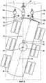
На фиг.13 представлен схематичный вид в плане задней части основного шасси 18, при этом второстепенные механические детали опущены, предназначенный для показа расположения основных деталей подсистемы 410. Дополнительное шасси 20 шарнирно соединено с основным шасси 18 с возможностью поворота вокруг вертикальной оси 23 и имеет три колесные пары 21.On Fig presents a schematic plan view of the rear of the
Втулочные элементы 412а и 412b прикреплены к дополнительному шасси 20 посредством шарниров 413а и 413b, вследствие чего они могут поворачиваться вокруг вертикальных осей поворота посредством шарниров 413а и 413b. Втулочные элементы 412а и 412b имеют трубчатую форму, за исключением участков возле шарниров 413а и 413b. Стержневые элементы 414а и 414b прикреплены к V-образному соединительному элементу (к вилке) 415 и могут скользить внутри втулочных элементов 412а и 412b. Стержневые элементы 414а и 414b на участке, соответствующем части длины, имеют упоры 416а и 416b, которые ограничивают расстояние, на которое они могут проникать в соответствующие втулочные элементы 412а и 412b.The
V-образный соединительный элемент 415 находится на заднем конце ползуна 417, который может скользить в направляющей 418, закрепленной на продольной центральной линии 24 основного шасси 18. Гидравлический цилиндр 420 присоединен между передним концом ползуна 417 и соединительным элементом 419, закрепленным на продольной центральной линии основного шасси 18. Когда ползун 417 перемещается вперед, жидкость из поршневой полости цилиндра 420 закачивается в трубку 421, а жидкость из трубки 422 вытягивается в штоковую полость цилиндра 420. Обратное происходит тогда, когда ползун 417 перемещается назад.A V-shaped connecting
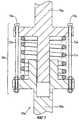
На фиг.14 представлен схематичный вид в плане подсистемы 411, расположенной на переднем конце основного шасси 18, при этом второстепенные детали опущены. На основном шасси 18 расположен дисковый кулачок 423, выполненный с возможностью поворота (способом, описанным ниже) вокруг вертикальной оси 19 относительно основного шасси 18 согласованно с поворотом тягачом 16. То есть наблюдатель на основном шасси видит дисковый кулачок 423 поворачивающимся вокруг оси 19 относительно основного шасси 18 тогда, когда тягач 16 совершает поворот.FIG. 14 is a schematic plan view of a
Ползун 424 имеет на переднем конце ролик 425, работающий по кулачку, который прилегает к фасонной кромке 426 дискового кулачка 423. Ползун 424 может скользить внутри направляющей 427, закрепленной вдоль продольной центральной линии 24 основного шасси 18. Гидравлический цилиндр 428 закреплен на заднем конце ползуна 424. Трубки 422 и 421 проходят вперед от цилиндра 420 и соединены соответственно со штоковой и поршневой полостями цилиндра 428.The
Третий гидравлический цилиндр 429 одностороннего действия расположен между цилиндрами 420 и 428, при этом его поршневая полость соединена с трубкой 421. Поршневой шток 430 цилиндра 429 прикреплен к ползуну 431, который может скользить по направляющим штангам 432, закрепленным на основном шасси 18. Сжимающая сила поддерживается в поршневом штоке 430 за счет предварительного напряжения винтовой пружины 433, которая находится на основном шасси 18 между ползуном 431 и пластиной 434. Посредством этого рабочая жидкость в подсистемах 410 и 411 поддерживается под достаточно высоким давлением для перемещения ползунов 417 и 424 соответственно вперед и назад так, чтобы зазоры в подсистемах 410 и 411 отсутствовали. В частности, когда тягач 16, основное шасси 18 и дополнительное шасси 20 находятся в выровненном положении для прямолинейного движения вперед, ролик 425, работающий по кулачку, удерживается в соприкосновении с кромкой 426 дискового кулачка 423, а ползун 417 и стержневые элементы 414а и 414b перемещаются назад до тех пор, пока не задерживаются зацеплением между упорами 416а и 416b и втулочными элементами 412а и 412b соответственно.A third single-acting
Дисковый кулачок 423 имеет форму лепестка с переменным радиусом вокруг оси 19, вследствие чего в том случае, когда он поворачивается согласованно с тягачом 16 из положения прямолинейного движения в положение поворота, ролик 425, работающий по кулачку, может постепенно перемещаться дальше вперед. В случае, например, правого поворота транспортного средства 15 естественное стремление дополнительного шасси 20 катиться прямолинейно вперед означает, что втулочный элемент 412b перемещается к упору 416b, вследствие чего ползун 417 перемещается вперед, а рабочая жидкость закачивается между цилиндром 420 и цилиндром 428. Это приводит к тому, что перемещение ползуна 424 также вперед ограничивается соприкосновением между роликом 425 и дисковым кулачком 423. Этим способом допустимый поворот дополнительного шасси 20 ограничивается углом 26' (между осями 24 и 25), который изменяется в зависимости от угла между тягачом 16 и основным шасси 18.The
Отметим, что степень предварительной нагрузки и усилие на единицу величины деформации (то есть упругую характеристику пружины) пружины 433 выбирают так, чтобы во время обычного поворота не было заметного вытеснения рабочей жидкости из цилиндра 420, принимаемой цилиндром 429. Однако дело обстоит так, что резкое уменьшение угла поворота тягача 16 на небольших скоростях (рассмотренное выше) не приводит к чрезмерному повышению давления рабочей жидкости, поскольку в этих случаях цилиндр 429 может отбирать жидкость при соответствующей деформации пружины 433. В данном случае цилиндр 429 и пружина 433 выполняют ту же самую функцию, что и упругие секции 68а и 68b устройства 60. Аналогичным образом резкое увеличение угла поворота на небольших скоростях приводит просто к временному отделению ролика 425 от дискового кулачка 423. При входе рабочей жидкости в цилиндр 429 необходимо отводить жидкость из линии 422. Это может быть сделано несколькими способами. Один заключается в соединении штоковой полости цилиндра 429 с линией 422, если цилиндры 420, 428 и 429 имеют одинаковые диаметры (непоказанные) канала и штока. Другой заключается в отведении жидкости из линии 422 в резервуар (непоказанный), поддерживаемый при низком давлении (гидравлический аккумулятор). Цилиндры 420, 428 и 429 также могут быть цилиндрами одностороннего действия.Note that the degree of preload and the force per unit strain (i.e., the elastic characteristic of the spring) of the
Очевидно, что вместо гидравлического соединения, описанного выше, ползуны 417 и 424 могут быть соединены стержнем (непоказанным), вытянутым вдоль оси 24 основного шасси 18, при этом стержень должен иметь упругий элемент (непоказанный), действующий по тому же самому принципу, что и элементы 68а и 68b. Такое устройство является вариантом устройства 60 и находится в рамках изобретения.Obviously, instead of the hydraulic connection described above, the
Фиксация дополнительного шасси на основном шасси прицепа относится к транспортному средству 15 и к регулировочному стопорному устройству 60, но в равной степени применима к транспортному средству 29 и к альтернативному регулировочному стопорному устройству 410/411. Для этих конкретных случаев желательно обеспечить фиксацию дополнительного шасси 20 на основном шасси 18. Высокая скорость движения вперед является примером того, когда желательно иметь дополнительное шасси 20, прикрепленное к основному шасси 18 с выравниванием осей 24 и 25.The fixation of the additional chassis on the main chassis of the trailer refers to the
В этой ситуации отклонения от положений прямолинейного движения вперед тягача 16 и дополнительного шасси 20 весьма ограничены. На фиг.9 (на которой опущены второстепенные механические детали) показано дополнительное шасси 20 с шипом 75 и фиксирующими сегментами 76а и 76b, приводимыми в действие пневматическими приводами 77, 78а и 78b соответственно, которые закреплены на основном шасси 18.In this situation, deviations from the straight forward positions of the
Шип 75 скользит в направляющей 79, прикрепленной к основному шасси 18, и при вхождении во взаимодействующую выемку в дополнительном шасси используется для фиксации дополнительного шасси 20 в выровненном по прямой линии положении.The
На основном шасси 18 неподвижно закреплен воздушный клапан 81, приводимый в действие выступом 82 на дисковом кулачке 83, закрепленном на дополнительном шасси 20, тогда, когда оси 24 и 25 полностью совмещены с точностью до определенного небольшого угла. Кроме того, дополнительный воздушный клапан 84 неподвижно закреплен на основном шасси 18 (см. фиг.6, 11) и приводится в действие выступом 85 на удлинителе 86 радиального рычага 120 (или выступом 437 на дисковом кулачке 423 в случае подсистемы 411, см. фиг.16) тогда, когда оси 24 и 28 полностью совмещены с точностью до определенного небольшого угла. При соответствующем подключении источника воздуха (непоказанного и обычно находящегося на тягаче) клапаны 81 и 84 и пневматический привод 77 вызывают перемещение шипа 75 в выемку 80 и фиксацию дополнительного шасси 20 и основного шасси 18 относительно друг друга. В случае приложения большого управляющего воздействия, достаточного для поворота удлинителя 86 рычага 120 и изменения состояния клапана 84, шип 75 вытягивается и после этого дополнительное шасси 20 может поворачиваться вокруг оси 23.An
Конечно, после того как дополнительное шасси 20 зафиксировано в выровненном по прямой линии положении, рассмотренном выше, можно обычным способом осуществить расцепление, для чего необходим квалифицированный механик (в отличие от просто водителя). Поэтому при необходимости транспортное средство 1 может быть подготовлено к работе тем же самым способом, как и известное транспортное средство 1. Для движения задним ходом пользователь может этим способом закрепить дополнительное шасси 20 в выровненном положении.Of course, after the
Независимо от того, совмещены ли оси 24 и 25, дополнительное шасси 20 должно автоматически фиксироваться относительно основного шасси в том случае, когда на тягаче 16 включается передача заднего хода. Для этого выполнены фиксирующие сегменты 76а и 76b. При приведении в действие приводами 78а и 78b они поворачиваются назад, вследствие чего по меньшей мере один из них входит в зацепление с дугообразной зубчатой рейкой 87 на дополнительном шасси 20.Regardless of whether the
В случае необходимости движение задним ходом может осуществляться при выравнивании дополнительного шасси 20 и основного шасси 18 или, например для сложных маневров задним ходом, при закреплении дополнительного шасси 20 в повернутом положении.If necessary, reversing can be carried out when aligning the
В качестве альтернативы любой один или оба клапана 81 и 84, 88а могут быть заменены электрическими переключателями или другими подходящими преобразователями, и указанное выше функционально достигается обычным способом с использованием удовлетворяющей требованиям комбинации электрических/электронных и пневматических схем. В особенно простой конструкции для приведения в действие фиксирующих сегментов 76а и 76b может использоваться простая цепь переключения на задний ход. В качестве альтернативы может использоваться отдельная и специализированная цепь управления.Alternatively, any one or both of the
В качестве альтернативной конструкции дополнительного шасси описано дополнительное шасси 33 транспортного средства 29, и в частности, средства, посредством которых неприводные мосты 34 и 36 устанавливаются в ответ на поворот дополнительного шасси 33 относительно основного шасси 32, вследствие чего колеса 37 и 39 «управляются» в точном смысле слова. На фиг.10 схематично показан вид в плане дополнительного шасси 33, при этом второстепенные механические детали опущены. На фиг.15 показано дополнительное шасси 33 в одном возможном виде, выполненное с возможностью использования механического/гидравлического регулировочного стопорного средства, описанного выше (подсистемы 410 и 411).As an alternative construction of the additional chassis, the
Центральный неуправляемый неприводной мост 35 установлен поперек дополнительного шасси 33 обычным способом, известным в области техники, к которой относится изобретение, а именно с упругой подвеской, обеспечивающей значительное вертикальное перемещение моста 35 для амортизации на неровностях дороги, но при этом мост 35 всегда остается расположенным по существу поперек дополнительного шасси 33. Показанный мост 35 (фиг.15) установлен через посредство листовой рессоры 150 и рессорно-демпферного узла 151, но могут быть использованы другие конструкции, известные в области техники, к которой относится изобретение.The central uncontrolled
Управляемые неприводные мосты 34 и 36 и их колеса 37 и 39 соответственно установлены на рамах 106 и 107 соответственно по существу тем же самым способом, как и мост 35, установленный на дополнительном шасси 33. Рамы 106 и 107 закреплены под дополнительным шасси 33 и могут поворачиваться вокруг вертикальных осей 108 и 109 на дополнительном шасси 33 для управляемой ориентации мостов 34 и 36 и колес 37 и 39. Мосты 34 и 36 прикреплены к рамам 106 и 107 с помощью тех же самых средств, что и мост 35 к дополнительному шасси 33, а именно посредством листовых рессор 150 и рессорно-демпферных узлов 151, см. фиг.15.Steered
Соединительные элементы 110 и 111 соответственно соединяют рамы 106 и 107 с основным шасси 32. Соединительные элементы 110 и 111 соединяют шарниры 100 и 101, закрепленные на рамах 106 и 107 соответственно, с шарнирами 102 и 103 соответственно на основном шасси 32. Путем соответствующего выбора мест расположения шарниров 100 и 101 на рамах 106 и 107 и шарниров 102 и 103 на основном шасси 32, например так, как показано на фиг.10, нужным образом достигается управление поворотом колес 37 и 39 относительно дополнительного шасси 33.The connecting
На фиг.15 показаны шарниры 100 и 101, выступающие вверх из рам 106 и 107 через прорези 152 и 153 к соединительным элементам 110 и 111. Дополнительное шасси 33 прикреплено к основному шасси 32 через посредство плиты 154, снабженной поворотным круглым подшипником 155, расположенным ниже. На фиг.15 шарниры 102 и 103 закрыты, но они закреплены на основании элемента 156, который сам прикреплен к плите 154. Соединительные элементы 110 и 111 проходят через прорези 157 с гарантированным зазором в конструкции дополнительного шасси 33. Шарниры 413а и 413b подсистемы 410 показаны выступающими вверх от дополнительного шасси 33 через прорези 158.On Fig shows the
При выборе мест расположения шарниров для соединительных элементов 110 и 111 важно обеспечить, чтобы при повороте дополнительного шасси 33 угол между дополнительным шасси 33 и основным шасси 32 по существу ограничивался регулировочным стопорным средством 410/411 (или 60). Это не произойдет, если угол между осями 40 и 41, а также 41 и 42 (см. фиг.4) будет возрастать слишком быстро при увеличении ограниченного упором угла 159' между дополнительным шасси 33 и основным шасси 32. Необходима меньшая степень автоматического управления с тем, чтобы дополнительное шасси 33 поворачивалось до угла 159', ограниченного регулировочным стопорным средством, но с меньшим трением колес о поверхность дороги, чем в случае транспортного средства 15. Для получения удовлетворяющих требованиям углов поворота мостов 34 и 36 при заданных углах поворота дополнительного шасси 33 для заданной геометрии транспортного средства выбор подходящих мест расположения шарниров 100, 101, 102, 103 и протяженностей соединительных элементов 110 и 111 можно сделать просто методом проб и ошибок.When choosing the hinge locations for the connecting
Регулировочные стопорные средства (устройство 60 или 410/411) работают при наличии соединения между тягачом (16 или 30) и основным шасси (18 или 32) прицепа. Соединение тягача с регулировочным стопорным средством будет описано, сначала применительно к устройству 60.Adjusting locking means (
На фиг.11 и 12 показаны детали, посредством которых ползун 65 в регулировочном стопорном средстве 60 вынужден поворачиваться вокруг оси 19 согласованно с тягачом 16, совершающим поворот относительно прицепа 17 (для удобства здесь сделана ссылка на транспортное средство 15, но описанная ниже конструкция в равной степени применима к транспортному средству 29).11 and 12 show details by which the
Как лучше показано на фиг.11, из которой исключены некоторые второстепенные механические и конструктивные детали, вилки 63а и 63b и ползун 65 находятся между верхней плитой 112 основного шасси 18 и подкладной плитой 113, нижняя поверхность 114 которой при использовании прицепа 17 опирается на прицепное устройство 115 тягача 16. Поворотный шкворень 116, прикрепленный к прицепу 17 и расположенный ниже подкладной плиты 113, размещен и обычным способом закреплен во взаимодействующей выемке 117 прицепного устройства 115 тягача.As best shown in FIG. 11, from which some minor mechanical and structural parts are excluded, the
Ведущий штырь 118, параллельный поворотному шкворню 116, проходит через дугообразную прорезь 119 в подкладной плите 113 и прикреплен к радиальному рычагу 120, который установлен на верхней части поворотного шкворня 116, свободно поворачивается вокруг него и находится между верхней плитой 112 и подкладной плитой 113. Ведущий штырь 118 прикреплен к прицепному устройству 115 тягача 16 способом, описанным ниже, вследствие чего, когда тягач 16 поворачивается вокруг поворотного шкворня 116, ведущий штырь 118 поворачивается согласованно с тягачом 16 вокруг поворотного шкворня 116. Дугообразная прорезь 119 центрирована относительно поворотного шкворня 116 и выполнена достаточно протяженной для согласования с максимально допустимым углом относительного поворота прицепа 17 и тягача 16.The
Ползун 65 установлен на верхней удлиненной части штыря 118 и свободно поворачивается вокруг него.The
Для альтернативного устройства 410/411 разработана более простая, но аналогичная конструкция, см. фиг.16. Дисковый кулачок 423 установлен таким же образом, как и радиальный стержень 120, с возможностью поворота вокруг оси 19, а ведущий штырь 436 прикреплен к основанию дискового кулачка 423 и проходит вниз через дугообразную прорезь 435 в подкладной плите 113. Ведущий штырь 436 и прорезь 435 выполняют те же самые функции, что и ведущий штырь 118 и прорезь 119.For an
Теперь будет описан способ, которым ведущий штырь 118 (или 436) закреплен в фиксированном положении относительно прицепного устройства 115 тягача.Now will be described the way in which the leading pin 118 (or 436) is fixed in a fixed position relative to the
На фиг.12 показано только прицепное устройство 115 тягача 16 стандартного типа, хорошо известное в области техники, к которой относится изобретение, имеющее верхнюю поверхность 121, на которую опирается подкладная плита 113 прицепа 17, и имеющее выемку 117 для размещения поворотного шкворня 116. Выемка 117 находится на переднем конце прорези 122 с параллельными сторонами, выполненной в прицепном устройстве 115 тягача, а позади прорези 122 находится сужающаяся прорезь 123. Когда к тягачу 16 необходимо присоединить прицеп 17, тягач подают обратным ходом под передний конец прицепа 17 (который для этого обычным способом поддерживают на соответствующей высоте) так, чтобы поворотный шкворень 116 прицепа вошел в сужающуюся прорезь 123, далее в прорезь 122 и наконец разместился (и зафиксировался известным способом, не показанным) в выемке 117. В заключение немного опускают передний конец прицепа 17 с тем, чтобы его подкладная плита 113 расположилась на верхней поверхности 121 прицепного устройства 115 тягача. Эта процедура аналогична процедуре, которую обычно осуществляют в случае использования известного прицепа.12 shows only a
На нижнем конце ведущего штыря 118 закреплен ползун 552, который свободно скользит в согласованной прорези 553, выполненной в клиновидном элементе 554. Направление, в котором ползун 552 свободно скользит в элементе 554, указано на фиг.12 стрелкой "z". Ползун 552 удерживается захваченным в прорези 553 посредством удерживающей пластины 555, прикрепленной к клиновидному элементу 554 болтами 556. Винтовая пружина 557 расположена в прорези 553 между ползуном 552 и поверхностью 558. Клиновидный элемент 554 имеет сужающийся участок 559 и передний участок 560 с параллельными сторонами. Когда прицеп 17 не соединен с тягачом 16, клиновидный элемент 554 удерживается захваченным непосредственно под подкладной плитой 113, поскольку штырь 118 прикреплен к ползуну 552. При осуществлении процедуры по сочленению прицепа 17 с тягачом 16, описанной в предыдущем абзаце, клиновидный элемент 554 вводят в сужающуюся прорезь 123 прицепного устройства 115 тягача. Когда поворотный шкворень 116 достигает выемки 117, участок 560 с параллельными сторонами размещается (и точно устанавливается) в прорези 122 с параллельными сторонами. Сужающийся участок 559 размещен в сужающейся прорези 123. Пружина 557 продвигает клиновидный элемент 554 дальше вперед так, что он проходит в прорези 122 и 123 и надежно удерживает его, тогда как ведущий штырь 118 удерживается на нужном радиальном месте относительно поворотного шкворня 116 посредством радиального рычага 120.A
Таким образом, на прицепе 17 транспортируются все основные механические детали, необходимые для управления задним дополнительным шасси 20, а тягач 16 может быть обычным, при этом для работы с изобретенным прицепом 17 не нужна модификация механических узлов тягача (исключая снабжение источником сжатого воздуха для пневматических устройств и снабжение второстепенными пневматическими и/или электрическими устройствами, описанными выше). Это является важным практическим достоинством. Сужающийся участок 559 клиновидного элемента 554 может (а в идеальном случае так и происходит) сужаться так, что будет согласован с сужением сужающейся прорези 123 в прицепном устройстве 115 тягача. Однако, хотя ширина прорези 122 с параллельными сторонами стандартизована, в сужающихся прорезях (например, в прорези 123) прицепного устройства тягача используются разнообразные сужения, и желательно, чтобы один клиновидный элемент можно было использовать для ряда прицепных устройств тягача. Для этого сужающийся участок 559 клиновидного элемента 554 может иметь сужение, соответствующее максимальному сужению, ожидаемому на практике, но которое все же можно использовать с прицепными устройствами тягача, имеющими более узкие сужающиеся прорези, поскольку пружина 557 должна продвигать клиновидный элемент 554 насколько возможно дальше вперед в прицепное устройство 115 тягача. Передний участок 560 с параллельными сторонами должен все же размещаться и надежно удерживаться в прорези 122. На практике отклонение, которое можно компенсировать, обусловлено необходимостью размещения переднего участка 560 с параллельными сторонами достаточно далеко в прорези 122. Этот способ «подвода» управления к прицепу без каких-либо требований к модификации тягача сам является изобретением.Thus, on the
Конечно, можно изъять клиновидный элемент 554 из ползуна 552, для чего удалить пластину 555, а его просто выдвинуть, и затем вдвинуть в ползун 552 новую клиновидную пластину 554 с другим сужением, сжать пружину 557 и вновь установить пластину 555.Of course, you can remove the wedge-shaped
Многие варианты описанных выше осуществлений могут быть выполнены без отступления от сущности и объема изобретения.Many variations of the above embodiments may be made without departing from the spirit and scope of the invention.
Claims (20)
Translated fromRussianApplications Claiming Priority (2)
| Application Number | Priority Date | Filing Date | Title |
|---|---|---|---|
| AUPR1844AAUPR184400A0 (en) | 2000-12-01 | 2000-12-01 | Articulated vehicle wheel tracking mechanism |
| AUPR1844 | 2000-12-01 |
Publications (2)
| Publication Number | Publication Date |
|---|---|
| RU2003119459A RU2003119459A (en) | 2004-12-20 |
| RU2282551C2true RU2282551C2 (en) | 2006-08-27 |
Family
ID=3825881
Family Applications (1)
| Application Number | Title | Priority Date | Filing Date |
|---|---|---|---|
| RU2003119459/11ARU2282551C2 (en) | 2000-12-01 | 2001-11-30 | Trailer for trailer-train |
Country Status (13)
| Country | Link |
|---|---|
| US (1) | US7219913B2 (en) |
| EP (1) | EP1406807B1 (en) |
| CN (1) | CN1270932C (en) |
| AT (1) | ATE480440T1 (en) |
| AU (3) | AUPR184400A0 (en) |
| BR (1) | BR0115824A (en) |
| CA (1) | CA2436907C (en) |
| DE (1) | DE60143056D1 (en) |
| MX (1) | MXPA03004859A (en) |
| NZ (1) | NZ526249A (en) |
| RU (1) | RU2282551C2 (en) |
| WO (1) | WO2002044005A1 (en) |
| ZA (1) | ZA200304452B (en) |
Cited By (1)
| Publication number | Priority date | Publication date | Assignee | Title |
|---|---|---|---|---|
| RU2676402C1 (en)* | 2018-01-26 | 2018-12-29 | Андрей Валентинович Астапенко | Road-train trailer |
Families Citing this family (97)
| Publication number | Priority date | Publication date | Assignee | Title |
|---|---|---|---|---|
| US20090273159A1 (en) | 2007-05-05 | 2009-11-05 | American Heavy Moving and Rigging, Inc. | Dual lane multi-axle transport vehicle |
| ITVR20030061A1 (en)* | 2003-05-19 | 2004-11-20 | H T S Hydro Tech Systems S R L | PNEUMATIC CYLINDER DEVICE FOR ARTICULATED VEHICLES THAT, ACCORDING TO THE RELATIVE ROTATION ANGLE BETWEEN TRACTOR AND SEMI-TRAILER OR BETWEEN TRACTOR AND TRAILER, ASSUMES A CORRESPONDENT ANGULAR POSITION THAT TRANSMITS THE COMMAND OF A CORRESPOND |
| JP4496759B2 (en)* | 2003-10-29 | 2010-07-07 | 日産自動車株式会社 | Lane departure prevention device |
| ATE473900T1 (en) | 2003-11-13 | 2010-07-15 | Trackaxle Pty Ltd | POWERED STEERING CAR |
| MX2007001168A (en)* | 2004-07-29 | 2007-04-20 | Trackaxle Pty Ltd | Command steer assembly for an articulated vehicle. |
| CA2688205C (en)* | 2006-05-08 | 2014-11-18 | Mechanical System Dynamics Pty Ltd | Steering system for road transport vehicles |
| US7798510B2 (en)* | 2007-02-15 | 2010-09-21 | Scott Patrick Comstock | Multi-wheeled vehicle |
| GB2447672B (en) | 2007-03-21 | 2011-12-14 | Ford Global Tech Llc | Vehicle manoeuvring aids |
| US20090020982A1 (en)* | 2007-07-16 | 2009-01-22 | Buckingham Stephen S | Trailer steering mechanism |
| DE102007036429A1 (en)* | 2007-08-02 | 2009-02-05 | Deere & Company, Moline | A control system and method for operating a control system for steering an implement coupled to an agricultural utility vehicle |
| FR2948622B1 (en)* | 2009-07-29 | 2011-11-18 | Michelin Soc Tech | VEHICLE COMPRISING AT LEAST TWO AXLES. |
| US8335607B2 (en)* | 2010-02-12 | 2012-12-18 | Ronald A. Gatten | Method and apparatus for linking electric drive vehicles |
| CN101870308B (en)* | 2010-06-30 | 2012-01-25 | 刘志忠 | Semitrailer with forcibly steered wheels |
| US9290202B2 (en) | 2011-04-19 | 2016-03-22 | Ford Global Technologies, Llc | System and method of calibrating a trailer backup assist system |
| US9783230B2 (en) | 2011-04-19 | 2017-10-10 | Ford Global Technologies, Llc | Trailer backup assist system with off-shoot correction |
| US9555832B2 (en) | 2011-04-19 | 2017-01-31 | Ford Global Technologies, Llc | Display system utilizing vehicle and trailer dynamics |
| US9513103B2 (en) | 2011-04-19 | 2016-12-06 | Ford Global Technologies, Llc | Hitch angle sensor assembly |
| US9493187B2 (en) | 2011-04-19 | 2016-11-15 | Ford Global Technologies, Llc | Control for trailer backup assist system |
| US9290203B2 (en) | 2011-04-19 | 2016-03-22 | Ford Global Technologies, Llc | Trailer length estimation in hitch angle applications |
| US9969428B2 (en) | 2011-04-19 | 2018-05-15 | Ford Global Technologies, Llc | Trailer backup assist system with waypoint selection |
| US9335163B2 (en) | 2011-04-19 | 2016-05-10 | Ford Global Technologies, Llc | Trailer length estimation in hitch angle applications |
| US9434414B2 (en) | 2011-04-19 | 2016-09-06 | Ford Global Technologies, Llc | System and method for determining a hitch angle offset |
| US9238483B2 (en) | 2011-04-19 | 2016-01-19 | Ford Global Technologies, Llc | Trailer backup assist system with trajectory planner for multiple waypoints |
| US9499200B2 (en) | 2011-04-19 | 2016-11-22 | Ford Global Technologies, Llc | Trailer backup assist system with object detection |
| US8909426B2 (en) | 2011-04-19 | 2014-12-09 | Ford Global Technologies | Trailer path curvature control for trailer backup assist |
| US9937953B2 (en) | 2011-04-19 | 2018-04-10 | Ford Global Technologies, Llc | Trailer backup offset determination |
| US10196088B2 (en) | 2011-04-19 | 2019-02-05 | Ford Global Technologies, Llc | Target monitoring system and method |
| US9708000B2 (en) | 2011-04-19 | 2017-07-18 | Ford Global Technologies, Llc | Trajectory planner for a trailer backup assist system |
| US9004519B1 (en) | 2011-09-28 | 2015-04-14 | Geoffrey S. Beech | Tow bar controlled trailer and method |
| NL2008989C2 (en) | 2012-06-12 | 2013-12-16 | Broshuis B V | TRAILER WITH ADJUSTABLE CONTROL. |
| WO2014032124A1 (en)* | 2012-09-03 | 2014-03-06 | Geoffrey Paul Sandford | Self-steering bogie for a road vehicle |
| US9150248B2 (en) | 2012-09-28 | 2015-10-06 | Crisp & Crisp Inc. | Lowboy trailer with steerable rear assembly |
| EP2917070B1 (en)* | 2012-11-06 | 2016-03-23 | Scheuerle Fahrzeugfabrik GmbH | Heavy-load transport vehicle for transporting an elongated object |
| CN103057586B (en)* | 2013-01-28 | 2015-03-25 | 中联重科股份有限公司 | trailer steering control method, controller, trailer steering system and trailer |
| US9623904B2 (en) | 2014-06-03 | 2017-04-18 | Ford Global Technologies, Llc | Trailer curvature control with adaptive trailer length estimation |
| US9963004B2 (en) | 2014-07-28 | 2018-05-08 | Ford Global Technologies, Llc | Trailer sway warning system and method |
| US9517668B2 (en) | 2014-07-28 | 2016-12-13 | Ford Global Technologies, Llc | Hitch angle warning system and method |
| US9540043B2 (en) | 2014-07-30 | 2017-01-10 | Ford Global Technologies, Llc | Trailer backup assist system with active trailer braking for curvature control |
| US9340228B2 (en) | 2014-10-13 | 2016-05-17 | Ford Global Technologies, Llc | Trailer motion and parameter estimation system |
| US9315212B1 (en) | 2014-10-13 | 2016-04-19 | Ford Global Technologies, Llc | Trailer sensor module and associated method of wireless trailer identification and motion estimation |
| US9533683B2 (en) | 2014-12-05 | 2017-01-03 | Ford Global Technologies, Llc | Sensor failure mitigation system and mode management |
| US9607242B2 (en) | 2015-01-16 | 2017-03-28 | Ford Global Technologies, Llc | Target monitoring system with lens cleaning device |
| US9522699B2 (en) | 2015-02-05 | 2016-12-20 | Ford Global Technologies, Llc | Trailer backup assist system with adaptive steering angle limits |
| US10286950B2 (en) | 2015-02-10 | 2019-05-14 | Ford Global Technologies, Llc | Speed optimized trajectory control for motor vehicles |
| US9616923B2 (en) | 2015-03-03 | 2017-04-11 | Ford Global Technologies, Llc | Topographical integration for trailer backup assist system |
| US9804022B2 (en) | 2015-03-24 | 2017-10-31 | Ford Global Technologies, Llc | System and method for hitch angle detection |
| US9623859B2 (en) | 2015-04-03 | 2017-04-18 | Ford Global Technologies, Llc | Trailer curvature control and mode management with powertrain and brake support |
| US9744972B2 (en) | 2015-04-09 | 2017-08-29 | Ford Global Technologies, Llc | Trailer backup aid speed limiting via braking |
| US9840240B2 (en) | 2015-04-09 | 2017-12-12 | Ford Global Technologies, Llc | Trailer backup aid speed limiting via braking |
| CN104843098A (en)* | 2015-05-29 | 2015-08-19 | 河南骏通车辆有限公司 | Semitrailer with steering function |
| CN104875669B (en)* | 2015-06-05 | 2017-05-10 | 宝鸡石油机械有限责任公司 | Rotary derrick transport drag seat |
| US9676377B2 (en) | 2015-06-17 | 2017-06-13 | Ford Global Technologies, Llc | Speed limiting comfort enhancement |
| US9896126B2 (en) | 2015-07-08 | 2018-02-20 | Ford Global Technologies, Llc | Jackknife detection for vehicle reversing a trailer |
| US9981662B2 (en) | 2015-10-15 | 2018-05-29 | Ford Global Technologies, Llc | Speed limiting comfort enhancement |
| US10611407B2 (en) | 2015-10-19 | 2020-04-07 | Ford Global Technologies, Llc | Speed control for motor vehicles |
| US10384607B2 (en) | 2015-10-19 | 2019-08-20 | Ford Global Technologies, Llc | Trailer backup assist system with hitch angle offset estimation |
| US9836060B2 (en) | 2015-10-28 | 2017-12-05 | Ford Global Technologies, Llc | Trailer backup assist system with target management |
| US10017115B2 (en) | 2015-11-11 | 2018-07-10 | Ford Global Technologies, Llc | Trailer monitoring system and method |
| US10155478B2 (en) | 2015-12-17 | 2018-12-18 | Ford Global Technologies, Llc | Centerline method for trailer hitch angle detection |
| US9827818B2 (en) | 2015-12-17 | 2017-11-28 | Ford Global Technologies, Llc | Multi-stage solution for trailer hitch angle initialization |
| US9610975B1 (en) | 2015-12-17 | 2017-04-04 | Ford Global Technologies, Llc | Hitch angle detection for trailer backup assist system |
| US9796228B2 (en) | 2015-12-17 | 2017-10-24 | Ford Global Technologies, Llc | Hitch angle detection for trailer backup assist system |
| US9798953B2 (en) | 2015-12-17 | 2017-10-24 | Ford Global Technologies, Llc | Template matching solution for locating trailer hitch point |
| US9934572B2 (en) | 2015-12-17 | 2018-04-03 | Ford Global Technologies, Llc | Drawbar scan solution for locating trailer hitch point |
| US10011228B2 (en) | 2015-12-17 | 2018-07-03 | Ford Global Technologies, Llc | Hitch angle detection for trailer backup assist system using multiple imaging devices |
| US10005492B2 (en) | 2016-02-18 | 2018-06-26 | Ford Global Technologies, Llc | Trailer length and hitch angle bias estimation |
| CN105857394B (en)* | 2016-04-12 | 2018-11-20 | 西南交通大学 | A kind of tractor trailer train steering control device and its control method |
| US10106193B2 (en) | 2016-07-01 | 2018-10-23 | Ford Global Technologies, Llc | Enhanced yaw rate trailer angle detection initialization |
| US10046800B2 (en) | 2016-08-10 | 2018-08-14 | Ford Global Technologies, Llc | Trailer wheel targetless trailer angle detection |
| US10222804B2 (en) | 2016-10-21 | 2019-03-05 | Ford Global Technologies, Llc | Inertial reference for TBA speed limiting |
| US10773721B2 (en) | 2016-10-21 | 2020-09-15 | Ford Global Technologies, Llc | Control method using trailer yaw rate measurements for trailer backup assist |
| EP3379222B1 (en) | 2017-03-22 | 2020-12-30 | Methode Electronics Malta Ltd. | Magnetoelastic based sensor assembly |
| US10604184B2 (en) | 2017-08-31 | 2020-03-31 | Ford Global Technologies, Llc | Adaptive steering control for robustness to errors in estimated or user-supplied trailer parameters |
| US10710585B2 (en) | 2017-09-01 | 2020-07-14 | Ford Global Technologies, Llc | Trailer backup assist system with predictive hitch angle functionality |
| US10730553B2 (en) | 2017-09-27 | 2020-08-04 | Ford Global Technologies, Llc | Adaptive steering control for robustness to errors in estimated or user-supplied trailer parameters |
| CN108082311A (en)* | 2018-01-16 | 2018-05-29 | 孙亚军 | The semi-trailer that a kind of rear axle can turn to |
| US11014417B2 (en) | 2018-02-27 | 2021-05-25 | Methode Electronics, Inc. | Towing systems and methods using magnetic field sensing |
| US11135882B2 (en) | 2018-02-27 | 2021-10-05 | Methode Electronics, Inc. | Towing systems and methods using magnetic field sensing |
| US11491832B2 (en) | 2018-02-27 | 2022-11-08 | Methode Electronics, Inc. | Towing systems and methods using magnetic field sensing |
| DE18907724T1 (en) | 2018-02-27 | 2021-03-25 | Methode Electronics, Inc. | Towing systems and methods using magnetic field measurement |
| US11084342B2 (en) | 2018-02-27 | 2021-08-10 | Methode Electronics, Inc. | Towing systems and methods using magnetic field sensing |
| US11221262B2 (en) | 2018-02-27 | 2022-01-11 | Methode Electronics, Inc. | Towing systems and methods using magnetic field sensing |
| CN108556912B (en)* | 2018-06-08 | 2023-10-24 | 南通市广益机电有限责任公司 | Electrically driven steering chassis |
| CN109305223B (en)* | 2018-09-28 | 2023-09-15 | 潘建锋 | Automobile chassis and vehicle using same |
| US11077795B2 (en) | 2018-11-26 | 2021-08-03 | Ford Global Technologies, Llc | Trailer angle detection using end-to-end learning |
| US10814912B2 (en) | 2018-11-28 | 2020-10-27 | Ford Global Technologies, Llc | Trailer backup assist system having advanced user mode with selectable hitch angle limits |
| US10829046B2 (en) | 2019-03-06 | 2020-11-10 | Ford Global Technologies, Llc | Trailer angle detection using end-to-end learning |
| CN113597399B (en)* | 2019-03-20 | 2023-11-07 | 沃尔沃卡车集团 | Fifth wheel control for articulated vehicles |
| DE102019204442A1 (en)* | 2019-03-29 | 2020-10-01 | Goldhofer Ag | Heavy duty vehicle |
| US11702136B2 (en)* | 2019-09-18 | 2023-07-18 | Deere & Company | Reverse steering modes for agricultural vehicles |
| CN111252142B (en)* | 2020-03-20 | 2024-07-23 | 河南工学院 | Automobile frame with adjustable turning radius and control method |
| WO2021231890A1 (en)* | 2020-05-15 | 2021-11-18 | Spraying Systems Co | Steering controller and method for steering a tracking path of a trailer |
| US11560026B2 (en)* | 2020-11-06 | 2023-01-24 | GM Global Technology Operations LLC | System and method for hitch angle estimation |
| DE102020133017A1 (en) | 2020-12-10 | 2022-06-15 | Max Streicher Gmbh & Co. Kommanditgesellschaft Auf Aktien | HEAVY DUTY TRANSPORT DEVICE |
| CN114115260B (en)* | 2021-11-22 | 2024-08-06 | 河北优控新能源科技有限公司 | Vehicle model building and path tracking control method for automatic driving articulated vehicle |
| CA3178011A1 (en)* | 2022-03-11 | 2023-09-11 | Gerard Noel | Vehicle steering wheels system |
| CN114834550B (en)* | 2022-05-24 | 2023-05-16 | 中建四局安装工程有限公司 | Pipeline transfer device for buried sewage plant |
Citations (3)
| Publication number | Priority date | Publication date | Assignee | Title |
|---|---|---|---|---|
| SU1303478A2 (en)* | 1985-05-06 | 1987-04-15 | Могилевский Машиностроительный Институт | Trailer |
| SU1533932A1 (en)* | 1987-05-29 | 1990-01-07 | Республиканский Проектно-Технологический Институт "Укроргтехстрой" | Vehicle steering control device |
| US5246242A (en)* | 1990-10-05 | 1993-09-21 | Paccar Inc. | Passively steered tandem axle group |
Family Cites Families (59)
| Publication number | Priority date | Publication date | Assignee | Title |
|---|---|---|---|---|
| US2384092A (en)* | 1943-07-27 | 1945-09-04 | Hollos Zsigmond | Mechanical drive mechanism for vehicles |
| US3149858A (en)* | 1960-12-29 | 1964-09-22 | Gilbert Le Roy | Steerable trailer vehicle |
| US3092398A (en)* | 1961-08-18 | 1963-06-04 | Gordon W Droeske | Tractor-trailer wheel steering assembly |
| US3168332A (en)* | 1962-11-28 | 1965-02-02 | Eynon Llewellyn | Trailer hitch |
| US3290052A (en)* | 1963-06-18 | 1966-12-06 | Stanley Steel Company Ltd | Multi-axle trailers |
| US3337234A (en)* | 1964-02-18 | 1967-08-22 | Kawasaki Rolling Stock Mfg Co | Steering arrangement for full trailers |
| US3403743A (en)* | 1966-11-21 | 1968-10-01 | Robert C. Daymon | Multiple wheel drive and steering vehicle |
| DE1630626A1 (en) | 1967-08-24 | 1971-06-09 | Kaessbohrer Fahrzeug Karl | Low loader trailer with cranked loading bridge |
| US3561790A (en)* | 1968-10-11 | 1971-02-09 | Herman E Jurgens | Self-steering and backable trailer |
| US3533645A (en)* | 1968-10-21 | 1970-10-13 | Meigs W Newberry | Close tracking trailer vehicle |
| US3533644A (en)* | 1969-02-24 | 1970-10-13 | Carl E Humes | Steering assembly for trailers |
| US3690698A (en)* | 1970-11-30 | 1972-09-12 | Carl E Humes | Steering assembly for trailers |
| US3734538A (en)* | 1970-11-30 | 1973-05-22 | C Humes | Steering assembly for trailers |
| US3700255A (en)* | 1971-06-18 | 1972-10-24 | Daniel H Herbert | Pivotable axle |
| US3712641A (en)* | 1971-11-15 | 1973-01-23 | Dana Corp | Steering system for trailers |
| US3899188A (en)* | 1974-02-11 | 1975-08-12 | Auto Steering Trailers Ltd | Self-steering bogies for trailers |
| NL7407708A (en)* | 1974-06-07 | 1975-12-09 | Hulo B V | STEERABLE MULTI-AXLE BOGIE FOR THE TRAILER COMBINATION TRAILER. |
| US3883158A (en)* | 1974-07-29 | 1975-05-13 | Pointer Willamette Trailer Co | Vehicle with steerable rear wheels |
| US4017094A (en)* | 1975-10-16 | 1977-04-12 | Robert Dwayne Pilcher | Steering converter apparatus |
| CA1042938A (en)* | 1976-01-06 | 1978-11-21 | Alma Mecanic Inc. | Truck trailer with a steering bogle |
| AU493669B2 (en)* | 1977-01-06 | 1978-06-22 | Single Track Steer Pty. Limited | Vehicle suspension system |
| US4120509A (en)* | 1977-04-22 | 1978-10-17 | Richard James Reeve | Self-steering tandem axle bogie |
| BE859923A (en) | 1977-10-20 | 1978-02-15 | Ekselse Konstruktie Werken P V | DEVICE FOR STEERING AXLES WITH WHEELS OF SEMI-TRAILERS AND TRAILERS |
| DE2936766A1 (en)* | 1979-09-12 | 1981-04-02 | Daimler-Benz Ag, 7000 Stuttgart | CONTROL FOR TRACKING AXLES |
| CS254307B2 (en)* | 1980-03-11 | 1988-01-15 | Sverre Damm | Control device for multiaxle trailers with lenghthening piece |
| WO1983002758A1 (en)* | 1982-02-10 | 1983-08-18 | Caswell, Kennith | Improvements relating to vehicle steering mechanisms |
| US4484758A (en)* | 1982-11-26 | 1984-11-27 | Harley Murray, Inc. | Self-steering trailer |
| SU1074755A1 (en)* | 1982-12-10 | 1984-02-23 | Проектно-Конструкторское Бюро Министерства Сельского Строительства Бсср | Apparatus for steering semitrailer wheels |
| US4586578A (en)* | 1982-12-21 | 1986-05-06 | Muiltidrive Limited | Articulated vehicle |
| SE446844B (en)* | 1983-04-29 | 1986-10-13 | Jarlsson Assar Karl Johan | COUNTRY SVEG STAG |
| CH655471B (en) | 1984-01-19 | 1986-04-30 | ||
| US4702488A (en)* | 1984-12-14 | 1987-10-27 | Atlantic Richfield Company | Steering system for tractor-trailer units |
| EP0233167B1 (en) | 1986-01-13 | 1991-07-17 | Ets JOSKIN S.A. | Mounting system for swivelling bogies |
| AU7365987A (en) | 1986-05-28 | 1987-12-03 | Road Transport Industries Australia Pty. Ltd. | Multi-axled vehicle steering system |
| US5029583A (en)* | 1986-07-22 | 1991-07-09 | Personal Diagnostics, Inc. | Optical analyzer |
| US4824135A (en)* | 1986-11-10 | 1989-04-25 | Mcgregor Donald T | Automatic self-steering trailer axle |
| FR2611635B1 (en) | 1987-02-27 | 1991-03-15 | Billig Sarl Ets | CONTROL DEVICE FOR STEERING WHEELS OF A TRAILER, AND TRAILER EQUIPPED WITH SUCH A DEVICE |
| DE8713839U1 (en) | 1987-10-14 | 1987-12-17 | Doll Fahrzeugbau GmbH, 7603 Oppenau | Long timber transporter |
| FR2624820B1 (en) | 1987-12-18 | 1990-04-27 | Auffret Jean | MEANS OF CONNECTION BETWEEN A CHASSIS AND A SINGLE OR DOUBLE DIRECTIONAL TRAILER OR SEMI-TRAILER AXLE |
| US5207443A (en)* | 1988-05-12 | 1993-05-04 | Mitchell George W | Multiple axle trailers |
| US4982976A (en)* | 1988-12-14 | 1991-01-08 | Trailer Design And Engineering, Inc. | Method and apparatus for steering multiple axle trailers |
| US5035439A (en)* | 1989-05-02 | 1991-07-30 | Petrillo Patrick G | Method and means for providing rear steerability in a trailer assembly |
| US4955630A (en)* | 1989-06-05 | 1990-09-11 | Ogren Axel E | Fifth wheel activated trailer steering |
| SE469066B (en) | 1990-10-23 | 1993-05-10 | Volvo Ab | WHEEL DRIVE FOR MOTOR VEHICLE |
| US5213353A (en)* | 1991-12-16 | 1993-05-25 | Williams Herbert F | Truck trailer steering apparatus |
| US5201836A (en)* | 1992-03-13 | 1993-04-13 | Dewitt Nicklas R | Automatic trailer steering mechanism |
| AU664919B2 (en) | 1992-06-29 | 1995-12-07 | Queensland Transport Industries Pty. Ltd. | Vehicle steering apparatus |
| CA2077039C (en)* | 1992-08-27 | 1997-05-20 | Maurice Demong | Steering system for plurality of vehicles |
| FR2705620B1 (en)* | 1993-04-19 | 1995-07-07 | Lohr Ind | Vehicle made up of a series of modules linked together by an articulated composite link. |
| WO1995015271A1 (en) | 1993-12-01 | 1995-06-08 | Donald Barry Sibbald | Self-steering suspension system for vehicles |
| FR2715624B1 (en)* | 1994-01-28 | 1996-03-15 | Lohr Ind | Directional control link for a rear steering road train. |
| DE4415294A1 (en) | 1994-04-30 | 1995-11-02 | Abb Patent Gmbh | Self-steering, three-axle bogie with steering beam |
| GB2315471B (en)* | 1996-07-24 | 1998-10-07 | Mitchell George W | Steerable trailers |
| US6131691A (en)* | 1996-09-13 | 2000-10-17 | Morch & Sonner A/S | System for guided steering of at least one set of wheels of a semi-trailer or a trailer |
| GB9623707D0 (en) | 1996-11-14 | 1997-01-08 | Muldoon Gerald | Linkage mechanism |
| US5830219A (en)* | 1997-02-24 | 1998-11-03 | Trex Medical Corporation | Apparatus for holding and driving a surgical cutting device using stereotactic mammography guidance |
| GB2328658B (en)* | 1997-08-02 | 2002-02-13 | Stephen Carl Henderson | Steering correction mechanism |
| US6170848B1 (en)* | 1998-12-22 | 2001-01-09 | Joy Mm Delaware, Inc. | System and related method for steering an articulated train |
| US7041068B2 (en)* | 2001-06-12 | 2006-05-09 | Pelikan Technologies, Inc. | Sampling module device and method |
- 2000
- 2000-12-01AUAUPR1844Apatent/AUPR184400A0/ennot_activeAbandoned
- 2001
- 2001-11-30AUAU2300902Apatent/AU2300902A/enactivePending
- 2001-11-30AUAU2002223009Apatent/AU2002223009B2/ennot_activeCeased
- 2001-11-30CACA002436907Apatent/CA2436907C/ennot_activeExpired - Fee Related
- 2001-11-30USUS10/433,061patent/US7219913B2/ennot_activeExpired - Fee Related
- 2001-11-30NZNZ526249Apatent/NZ526249A/enunknown
- 2001-11-30EPEP01998469Apatent/EP1406807B1/ennot_activeExpired - Lifetime
- 2001-11-30RURU2003119459/11Apatent/RU2282551C2/ennot_activeIP Right Cessation
- 2001-11-30DEDE60143056Tpatent/DE60143056D1/ennot_activeExpired - Lifetime
- 2001-11-30WOPCT/AU2001/001559patent/WO2002044005A1/ennot_activeApplication Discontinuation
- 2001-11-30ATAT01998469Tpatent/ATE480440T1/ennot_activeIP Right Cessation
- 2001-11-30MXMXPA03004859Apatent/MXPA03004859A/enactiveIP Right Grant
- 2001-11-30BRBR0115824-4Apatent/BR0115824A/ennot_activeApplication Discontinuation
- 2001-11-30CNCNB018219004Apatent/CN1270932C/ennot_activeExpired - Fee Related
- 2003
- 2003-06-06ZAZA200304452Apatent/ZA200304452B/enunknown
Patent Citations (3)
| Publication number | Priority date | Publication date | Assignee | Title |
|---|---|---|---|---|
| SU1303478A2 (en)* | 1985-05-06 | 1987-04-15 | Могилевский Машиностроительный Институт | Trailer |
| SU1533932A1 (en)* | 1987-05-29 | 1990-01-07 | Республиканский Проектно-Технологический Институт "Укроргтехстрой" | Vehicle steering control device |
| US5246242A (en)* | 1990-10-05 | 1993-09-21 | Paccar Inc. | Passively steered tandem axle group |
Cited By (1)
| Publication number | Priority date | Publication date | Assignee | Title |
|---|---|---|---|---|
| RU2676402C1 (en)* | 2018-01-26 | 2018-12-29 | Андрей Валентинович Астапенко | Road-train trailer |
Also Published As
| Publication number | Publication date |
|---|---|
| CA2436907C (en) | 2007-09-11 |
| MXPA03004859A (en) | 2005-02-14 |
| WO2002044005A1 (en) | 2002-06-06 |
| AUPR184400A0 (en) | 2001-01-04 |
| NZ526249A (en) | 2004-11-26 |
| CA2436907A1 (en) | 2002-06-06 |
| DE60143056D1 (en) | 2010-10-21 |
| EP1406807A1 (en) | 2004-04-14 |
| ZA200304452B (en) | 2004-09-06 |
| US7219913B2 (en) | 2007-05-22 |
| EP1406807B1 (en) | 2010-09-08 |
| AU2300902A (en) | 2002-06-11 |
| CN1270932C (en) | 2006-08-23 |
| US20040104555A1 (en) | 2004-06-03 |
| ATE480440T1 (en) | 2010-09-15 |
| EP1406807A4 (en) | 2007-12-12 |
| BR0115824A (en) | 2004-04-20 |
| AU2002223009B2 (en) | 2006-03-09 |
| CN1486259A (en) | 2004-03-31 |
Similar Documents
| Publication | Publication Date | Title |
|---|---|---|
| RU2282551C2 (en) | Trailer for trailer-train | |
| AU2002223009A1 (en) | Articulated Vehicle Wheel Tracking Mechanism | |
| US6695328B2 (en) | Vehicle frame assembly and split-frame vehicle | |
| KR100576792B1 (en) | Steering System for a Multiple-Axle Vehicle | |
| FI74666B (en) | ANORDNING FOER STABILIZERING AV RAKGAONG OCH FOER AENDRING AV STAELLNING PAO FOERVAEG BESTAEMDA BANOR FOER FORDONSAXLAR. | |
| EP0400033B1 (en) | Suspension of a steerable wheel axle of a tractor | |
| CS254307B2 (en) | Control device for multiaxle trailers with lenghthening piece | |
| EP0544727B1 (en) | Vehicle | |
| US4267779A (en) | Mechanically trackable road vehicle | |
| EP0100351B1 (en) | Improvements relating to vehicle steering mechanisms | |
| US6182984B1 (en) | Reversible caster steerable suspension system | |
| US5163698A (en) | Log trailer load extension axle assembly | |
| US7686320B1 (en) | Steering system for a tractor and trailer | |
| US5784967A (en) | Rear steering axle directional control linkage for road vehicles | |
| US5088570A (en) | Steerable rear dual axle system for large trucks | |
| US4117901A (en) | Self-propelled articulated vehicle | |
| US6932173B2 (en) | Steered vehicle | |
| US6231061B1 (en) | Vehicle frame assembly and split-frame vehicle | |
| EP0295589B1 (en) | Short coupling system | |
| AU2006253766B2 (en) | Trailer towing-control apparatus | |
| JP2590012B2 (en) | Trailer wheel steering | |
| JPH06219314A (en) | Steering device | |
| RU92843U1 (en) | SEMITRAILER WHEEL CONTROL SYSTEM | |
| WO2011065866A1 (en) | System for controlling the wheels of a semi-trailer | |
| EP2457767A1 (en) | A semi-trailer load carriage for rail-bound vehicles and method of loading the rail car |
Legal Events
| Date | Code | Title | Description |
|---|---|---|---|
| MM4A | The patent is invalid due to non-payment of fees | Effective date:20101201 |