RU2275972C1 - Device for double-sided cleaning of plates - Google Patents
Device for double-sided cleaning of platesDownload PDFInfo
- Publication number
- RU2275972C1 RU2275972C1RU2004126122/12ARU2004126122ARU2275972C1RU 2275972 C1RU2275972 C1RU 2275972C1RU 2004126122/12 ARU2004126122/12 ARU 2004126122/12ARU 2004126122 ARU2004126122 ARU 2004126122ARU 2275972 C1RU2275972 C1RU 2275972C1
- Authority
- RU
- Russia
- Prior art keywords
- plate
- plates
- carrier
- rollers
- symmetry
- Prior art date
Links
- 238000004140cleaningMethods0.000titleclaimsabstractdescription28
- 230000007246mechanismEffects0.000claimsabstractdescription76
- 239000000969carrierSubstances0.000claimsabstractdescription4
- 238000000034methodMethods0.000claimsdescription6
- 238000007599dischargingMethods0.000abstract2
- 239000000126substanceSubstances0.000abstract1
- 238000005406washingMethods0.000description7
- 238000011109contaminationMethods0.000description4
- 238000004519manufacturing processMethods0.000description4
- 239000008367deionised waterSubstances0.000description3
- 229910021641deionized waterInorganic materials0.000description3
- 230000003993interactionEffects0.000description3
- XLYOFNOQVPJJNP-UHFFFAOYSA-NwaterChemical compoundOXLYOFNOQVPJJNP-UHFFFAOYSA-N0.000description3
- 238000001035dryingMethods0.000description2
- 239000000758substrateSubstances0.000description2
- 101100043261Caenorhabditis elegans spop-1 geneProteins0.000description1
- 239000003795chemical substances by applicationSubstances0.000description1
- 238000006073displacement reactionMethods0.000description1
- 239000012535impuritySubstances0.000description1
- 239000007788liquidSubstances0.000description1
- 230000008092positive effectEffects0.000description1
- 230000000284resting effectEffects0.000description1
- 239000004065semiconductorSubstances0.000description1
- 235000012431wafersNutrition0.000description1
Images


Landscapes
- Cleaning Or Drying Semiconductors (AREA)
- Cleaning In General (AREA)
Abstract
Description
Translated fromRussianИзобретение относится к производству изделий электронной техники и может быть использовано, например, на операциях двухсторонней очистки пластин с помощью щеток и мегазвука.The invention relates to the manufacture of electronic products and can be used, for example, in operations of two-sided cleaning of plates using brushes and megasound.
Широко известны различные устройства для обработки пластин [1-3], содержащие блок обработки пластин, загрузочные и разрузочные устройства, транспортирующий механизм. Однако известные устройства позволяют транспортировать пластины на позицию обработки в горизонтальной плоскости и не могут быть использованы для двухсторонней отмывки пластин. Причем в качестве транспортирующих средств используют пассики, вакуумные захваты, что приводит к загрязнению пластин после их обработки.Various devices for processing plates [1-3] are widely known, comprising a plate processing unit, loading and unloading devices, and a transporting mechanism. However, the known devices can transport the plate to the processing position in the horizontal plane and cannot be used for two-sided washing of the plates. Moreover, passives and vacuum grippers are used as transporting agents, which leads to fouling of the plates after their processing.
Из известных аналогов наиболее близким по технической сущности и достигаемому результату является устройство для двухсторонней обработки подложек [5], содержащее устройство для транспортировки их. Транспортирующее устройство включает в себя разгрузочную и загрузочную (пустую) кассеты, установленные на основаниях двух механизмов шагового перемещения их. Механизмы вертикального перемещения снабжены приспособлением для транспортировки пластин в кассету и из кассеты, выполненным в виде держателя с пазом. Механизм горизонтального перемещения с помощью вакуумного захвата переносит пластину на рабочую позицию блока очистки, а затем на позицию загрузки обработанной пластины в кассету.Of the known analogues, the closest in technical essence and the achieved result is a device for two-sided processing of substrates [5], containing a device for transporting them. The transporting device includes an unloading and loading (empty) cassette mounted on the bases of two mechanisms for moving them stepwise. The vertical movement mechanisms are equipped with a device for transporting plates to and from the cartridge, made in the form of a holder with a groove. The horizontal movement mechanism using a vacuum grip transfers the plate to the working position of the cleaning unit, and then to the loading position of the processed plate in the cassette.
Недостаток известного устройства заключается в том, что оно, как и все известные, не обеспечивает качественную очистку из-за вносимых загрязнений вакуумным захватом. При изготовлении же структур с очень малыми размерами (порядка 0,3 мкм) предъявляются высокие требования к качеству очистки.A disadvantage of the known device is that it, like all known devices, does not provide high-quality cleaning due to the impurities introduced by vacuum capture. In the manufacture of structures with very small sizes (of the order of 0.3 microns), high demands are placed on the quality of cleaning.
Целью предложенного изобретения является повышение качества очистки пластин.The aim of the invention is to improve the quality of cleaning plates.
Поставленная цель достигается тем, что устройство для двухсторонней очистки пластин, содержащее установленные на основании разгрузочную и загрузочную кассеты, два механизма шагового перемещения их, механизм вертикального перемещения пластин из разгрузочной кассеты, механизм вертикального перемещения пластин в загрузочную кассету, механизм горизонтального перемещения пластин, снабженный захватом, блок очистки пластин, дополнительно снабжено (п-1) блоками очистки, где n - число технологических ванн блоков очистки, определяемое технологическим процессом, вторым механизмом горизонтального перемещения, снабженным захватом, при этом каждый механизм вертикального перемещения пластин снабжен носителем пластин, выполненным в виде сектора тонкого кольца, имеющего на внутреннем круговом торце сектора круговую канавку с V-образной заходной частью и содержащего вертикальный паз, смещенный по горизонтали от оси симметрии сектора, а захват каждого механизма горизонтального перемещения выполнен в виде держателя, снабженного двумя роликами, имеющими круговые канавки с V-образной заходной частью, расстояние между наружными диаметрами которых больше ширины носителей, а также упором, имеющим канавку такого же профиля с V-образной заходной частью и расположенным ниже линии, проведенной через оси роликов и держателя таким образом, что его ось симметрии совпадает с осью симметрии вертикального паза на носителях пластин, при этом оси симметрии канавок роликов и упора лежат в одной плоскости, кроме того, каждый из n-блоков очистки снабжен механизмом загрузки-выгрузки пластин, выполненным в виде подвижной штанги с жестко закрепленным на ней носителем пластин, взаимодействующим с профилированными роликами, установленными в технологических ваннах, выполненным аналогично носителю каждого механизма вертикального перемещения пластин и дополнительно снабженным сквозным отверстием по оси симметрии носителя.This goal is achieved in that a device for two-sided cleaning of plates containing the unloading and loading cassettes mounted on the base, two mechanisms for their step-by-step movement, a mechanism for vertical movement of the plates from the unloading cassette, a mechanism for vertical movement of the plates in the loading cassette, a mechanism for horizontal movement of the plates equipped with a grip , the plate cleaning unit, is additionally equipped with (n-1) cleaning units, where n is the number of technological baths of the cleaning units, determined by the technology a second process of horizontal movement equipped with a gripper, each vertical movement of the plates is provided with a plate carrier made in the form of a sector of a thin ring having a circular groove with a V-shaped inlet on the inner circular end of the sector and containing a vertical groove offset horizontally from the axis of symmetry of the sector, and the capture of each mechanism of horizontal movement is made in the form of a holder equipped with two rollers having circular grooves with a V-shape th lead part, the distance between the outer diameters of which is greater than the width of the carriers, as well as a stop having a groove of the same profile with a V-shaped lead part and located below the line drawn through the axes of the rollers and the holder so that its axis of symmetry coincides with the axis of symmetry vertical groove on the carrier plates, while the axis of symmetry of the grooves of the rollers and the stop lie in the same plane, in addition, each of the n-cleaning units is equipped with a mechanism for loading and unloading plates, made in the form of a movable rod with a rigid a plate carrier mounted on it, interacting with profiled rollers installed in the process baths, made similarly to the carrier of each mechanism for vertical movement of the plates and further provided with a through hole along the axis of symmetry of the carrier.
Введение дополнительных n-1 блоков очистки расширяет технологические возможности устройства, так как позволяет осуществлять несколько технологических процессов, например очистку пластин щетками, а также как более эффективную мегазвуковую очистку с последующей сушкой. А выполнение автономными для каждой технологической ванны механизмов загрузки-выгрузки пластин и конструктивно одинаковыми носителей позволяет обеспечить модульность изготовления блоков очистки и унифицировать процесс изготовления их.The introduction of additional n-1 cleaning units expands the technological capabilities of the device, as it allows several technological processes to be carried out, for example, brush cleaning of plates, as well as more effective megasonic cleaning with subsequent drying. And the implementation of autonomous for each technological bath mechanisms of loading and unloading plates and structurally the same media allows you to ensure the modularity of the manufacture of cleaning units and unify the process of manufacturing them.
Конструкция носителя, выполненного в виде сектора тонкого кольца с круговой канавкой и V-образной заходной частью и взаимодействующего с захватом и упором, имеющим канавку такого же профиля и V-образную заходную часть, обеспечивает надежный захват пластины, исключая колебания ее, и минимальный контакт пластины и транспортирующего устройства. Это сказывается на качестве обработки пластин.The design of the carrier, made in the form of a sector of a thin ring with a circular groove and a V-shaped lead-in and interacting with a grip and a stop having a groove of the same profile and a V-shaped lead, provides reliable grip of the plate, eliminating its vibrations, and minimal contact of the plate and transporting device. This affects the quality of the processing plates.
Кроме того, использование дополнительного механизма горизонтального перемещения с захватом (держателем) исключает загрязнение чистой пластины в процессе ее дальнейшей транспортировки.In addition, the use of an additional mechanism of horizontal movement with a gripper (holder) eliminates contamination of a clean plate during its further transportation.
Таким образом, предложенная совокупность признаков является новой, обеспечивает положительный эффект, указанный в цели изобретения, и не вытекает очевидным образом из известного уровня техники.Thus, the proposed combination of features is new, provides a positive effect specified in the purpose of the invention, and does not follow in an obvious manner from the prior art.
Следовательно, она соответствует критерию "изобретательский уровень" и "новизна".Therefore, it meets the criteria of "inventive step" and "novelty."
Сущность изобретения поясняется чертежами, где изображены:The invention is illustrated by drawings, which depict:
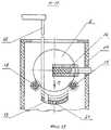
на фиг.1 - общий вид устройства;figure 1 - General view of the device;
на фиг.2 - вид сверху;figure 2 is a top view;
на фиг.3-4 - механизм вертикального перемещения, взаимодействие его с кассетой и с механизмом горизонтального перемещения;figure 3-4 - the mechanism of vertical movement, its interaction with the cartridge and with the mechanism of horizontal movement;
на фиг.5 - держатель механизма горизонтального перемещения;figure 5 - holder of the horizontal movement mechanism;
на фиг.6-7 - блок обработки пластин с помощью щеток и взаимодействие носителя блока обработки с держателем механизма горизонтального перемещения;Fig.6-7 - plate processing unit with brushes and the interaction of the carrier of the processing unit with the holder of the horizontal movement mechanism;
на фиг.8 - блок обработки с помощью мегазвука;on Fig - processing unit using megasound;
на фиг.9-10 - носитель второго блока обработки и его взаимодействие с держателем механизма горизонтального перемещения;Fig.9-10 - the carrier of the second processing unit and its interaction with the holder of the horizontal movement mechanism;
на фиг.11 - сечение ролика держателя;figure 11 is a cross section of the roller holder;
на фиг.12 - сечение упора держателя;on Fig - cross section of the holder;
на фиг.13-14 - носитель механизма вертикального перемещения;on Fig.13-14 - the carrier of the vertical movement mechanism;
на фиг.15 - ориентирующий механизм.on Fig - orienting mechanism.
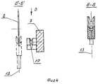
Предлагаемое устройство содержит две кассеты 1 с пластинами 2, установленные на основаниях 3 механизмов шагового перемещения 4, механизм вертикального перемещения 5 с носителем 6 для выгрузки пластин 2 из кассеты и передачи пластины на держатель 7 механизма горизонтального перемещения 8 (фиг.1, 2). Носитель 6 (фиг.3) выполнен в виде сектора тонкого кольца с параллельными сторонами и круговой канавкой с V-образной заходной частью.The proposed device contains two cassettes 1 with
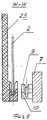
На фиг.3 изображены три положения носителя 6: I - носитель в исходном положении (внизу); II - носитель захватил пластину при движении вверх; III - носитель поднял пластину 2 из кассеты 1 и под пластину подошел держатель 7 с роликами 9 и упором 10. Ролики 9 держателя 7 изображены на фиг.11, а упор 10 - на фиг.12. Ролики имеют круговую канавку с таким же профилем, как и носитель 6. Такой же профиль канавки имеет и упор 10. Причем центры симметрии канавок роликов и упора находятся на расстоянии L от торца держателя (фиг.5, 11, 12). Расстояние Д между наружными диаметрами роликов 9 больше, чем ширина носителя Д′ (фиг.3). Центр симметрии упора 10 смещен относительно оси симметрии расположения роликов 9 держателя 7 на расстояние d (фиг.3, 5). Кроме того, упор расположен ниже линии, проведенной через оси роликов, что позволяет пластине войти в канавку упора и не касаться основания канавки упора. Между торцом пластины и основанием канавки упора выбрано расстояние δ (фиг.10) и таким образом пластина, опираясь только на ролики 9, удерживается упором 10, выполняющим роль удерживающей вилки. При этом оси симметрии канавок роликов и упора расположены на одной вертикальной плоскости.Figure 3 shows the three positions of the carrier 6: I - the carrier in its original position (bottom); II - the carrier captured the plate when moving up; III - the carrier lifted the
Механизм загрузки-выгрузки 11 пластин служит для перемещения штанги 12 и носителя 13 в блоке обработки пластин 2 щетками 14. Щетки 14 имеют возможность вращаться от привода 15 и разводиться в стороны с помощью механизма (привода) 16. Обработка щетками ведется в ванне 17, снабженной роликами 18 (фиг.6, 13), которые приводятся во вращение приводом 19 (фиг.2). Носитель 13, как и носитель 6, выполнен в виде сектора тонкого кольца с круговой канавкой с V-образной заходной частью на внутреннем круговом торце. Носители 6, 13 снабжены вертикальным пазом 20, смещенным по горизонтали от центра симметрии сектора на расстоянии d (фиг.3, 6). В отличие от носителя 6 носитель 13, закрепленный на подвижной штанге 12, направленной вверх, снабжен сквозным отверстием 21 для удаления остатков раствора из носителя после обработки. Второй механизм загрузки-выгрузки 22 (фиг.1) пластин служит для перемещения штанги 23 и носителя 24 в блоке мегазвуковой обработки. Обработка ведется мегазвуковой головкой (форсункой) 25, которая совершает в процессе обработки, при вращении пластины 2, возвратно-поступательное перемещение от привода 26 (фиг.2).The mechanism of loading and unloading 11 of the plates serves to move the
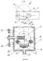
Пластина 2 при обработке в ванне 27 (фиг.8) устанавливается на роликах 28, имеющих круговые канавки с V-образной заходной частью. Ролики 28 установлены на роторе 29, имеющем привод вращения 30 через ременную передачу.
Механизм 22 имеет привод горизонтального перемещения 31 с целью возможности вывода штанги и носителя 24 из ванны 27 после установки пластины 2 на ролики 28 ротора 29. Вывод осуществляется для предохранения носителя 24 от загрязнений в процессе обработки пластины 2. Подача моющей жидкости осуществляется с обеих сторон пластины форсункой 25 и форсункой 32. Носитель 24 блока мегазвуковой обработки выполнен аналогичный носителю 13 блока обработки щетками.The mechanism 22 has a horizontal displacement drive 31 so that the rod and
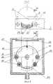
Загрузка пластин 2 на ротор 29 центрифуги блока мегазвуковой обработки осуществляется только в то время, когда ротор 29 сориентирован с помощью привода 33, ролика 34, диска 35 (фиг.15).The loading of the
Пластина 2 на роторе 29 закрепляется от выпадения во время вращения фиксатором 36, который перемещается с помощью приводов 37 и 38 (фиг.1). Заслонка 39 закрывает окно 40 ванны 27 во время обработки пластины.The
Механизм 41 с держателем 42 служит для перемещения пластин 2 от блока мегазвуковой обработки до приемной кассеты 1. Пустая приемная кассета аналогично разгрузочной установлена на основании 3 и перемещается на шаг с помощью механизма 4. Второй механизм вертикального перемещения 5 пластин в кассету после выполнения технологических операций также снабжен носителем 5, выполненным аналогично носителю механизма вертикального перемещения пластин из кассеты, который укладывает обработанные пластины в кассету.The
Работа устройства происходит следующим образом.The operation of the device is as follows.
Кассета 1 с пластинами 2 устанавливается на подвижное основание 3 в виде прямоугольной рамы. Основание 3 имеет возможность пошагового перемещения с помощью механизма 4 (фиг.1, 2). Приемная кассета 1 без пластин устанавливается на второе основание 3, которое имеет возможность пошагового перемещения с помощью второго механизма 4. Первая пластина в кассете 1 останавливается над носителем 6 механизма вертикального перемещения 5. А первая ячейка пустой приемной кассеты останавливается над носителем 5 механизма вертикального перемещения 5 пластин в кассету (фиг.1). Механизм вертикального перемещения 5 пластин из кассеты перемещает носитель 6 вверх и носитель 6 захватывает первую пластину кассеты, поднимает ее вверх. На фиг.3 показано три положения носителя 5: I положение - исходное положение (внизу), II положение - момент захвата пластины в кассете, III положение - верхнее положение носителя 5 с пластиной.The cassette 1 with the
Первый механизм горизонтального перемещения пластин 8 перемещает свой держатель 7 в сторону нахождения носителя 5 с пластиной. При этом держатель 7 своими роликами 9 и упором 10 заходит под пластину 2 таким образом, что ось 11 (фиг.3) расположения канавок на роликах 9 держателя и канавки на упоре 10 совпала с осью симметрии 13 канавки носителя 5, в которой помещается пластина 3 (фиг.3). При этом упор 10 держателя 8 заходит в вертикальный паз носителя 6. Затем механизм 5 опускает носитель 6 вниз на исходное положение I (фиг.3), а пластина 2 остается на роликах 9, удерживаясь от колебаний канавкой на упоре 10. Таким образом во время транспортировки контакт транспортирующего устройства с пластиной минимальный.The first mechanism for horizontal movement of the
Механизм 8 переносит держатель 7 с пластиной 2 вправо и останавливается над первым блоком 2-сторонней очистки пластины щетками. Механизм загрузки-выгрузки 11 пластин первого блока обработки в исходном положении (фиг.1) находится внизу, при этом его штанга 12, на которой закреплен носитель 13 (фиг.6, 7), находится в ванне 17. Щетки 14 разведены в сторону с помощью механизма 16.The
После остановки механизма 8 с держателем 7 и пластиной 2 над блоком 2-сторонней очистки пластины щетками механизм 11 поднимает штангу 12 с носителем 13 из ванны 17, носитель 13 доходит до пластины 2, расположенной на роликах 9 и упоре 10 держателя 7, пластина 2 попадает в канавку носителя и он поднимает пластину 2 над роликами 9 и упором 10. При этом упор 10 держателя 7 проходит в вертикальном пазу 20 носителя 13. Механизм 8 отводит держатель 7 с роликами 9 и упором 10 вправо. А пластина 2 остается на носителе 13.After stopping the
Механизм 11 (фиг.1, 6) опускает штангу 12, носитель 13 с пластиной 2 в ванну 17 через окно ванны 43, устанавливая пластину 2 на ролики 18. Щетки 14 с помощью механизма 16 прижимаются к пластине 2 и начинают вращаться от привода 15. Одновременно начинают вращаться ролики 18 от привода 19, заставляя вращаться пластину 2. Во время вращения щеток 14 и пластины 2 подаются соответствующие растворы на обе стороны пластины 2. Таким образом осуществляется отмывка одновременно двух сторон пластины 2 с помощью щеток. Во время отмывки щетками носитель 13 находится в ванне 17, располагаясь ниже уровня пластины и не мешая ей вращаться (фиг.6).The mechanism 11 (Figs. 1, 6) lowers the
После окончания процесса отмывки пластины щетками щетки 14 останавливаются и разводятся в сторону с помощью механизма 16. Ролики 18 тоже останавливаются и прекращается подача растворов. Для удаления израсходованных растворов в ванне 17 предусмотрено сливное отверстие 44. Механизм 11 (фиг.1) поднимает штангу 12, носитель вверх, носитель 13 снимает с роликов 18 пластину 2 и, продолжая подъем, доходит до крайнего верхнего положения 5 (фиг.6). Механизм 7 подводит справа под пластину 2 держатель 7 с роликами 9 и упором 10. Носитель 13 опускается, оставляя пластину 2 на роликах 9 и упоре 10 держателя 8 (фиг.10). Во время подъема пластины 2 из ванны 17 остатки моющего раствора с пластины удаляются через отверстие 21 в носителе 13. После передачи пластины с носителя 13 на держатель 7 после отмывки пластины щетками механизм 8 переносит пластину вправо и останавливает ее над следующим по ходу технологического процесса n-блоком обработки, например блоком мегазвуковой обработки.After the process of washing the plate with brushes, the
При этом штанга 23 механизма загрузки-выгрузки 22 пластин следующего блока обработки (фиг.1, 9) находится в нижнем положении в ванне 27 и правом положении за счет механизма 31.In this case, the
После остановки пластины 2, расположенной на держателе 8 механизма 7 над блоком мегазвуковой обработки, механизм 22 поднимает штангу 23, носитель 24 из ванны 27 вверх. При этом ротор 29 центрифуги с роликами 28 находится в ориентированном положении (фиг.8), а заслонка 39 - в отведенном состоянии. Фиксатор 36 ротора 29 находится в крайнем правом положении 36.After stopping the
За время подъема штанги 23 носитель 24 снимает пластину 2 с роликов 9 и упора 10 держателя 7, т.е. приподнимает пластину 2 вверх. Держатель 7 уходит вправо из-под пластины 2, оставшейся на носителе 24 (фиг.8).During the lifting of the
Штанга 23 с носителем 24 и пластиной 2 опускается в ванну 27 через окно 40. Пластина 2 укладывается на ролики 28 ротора 29. Носитель уходит ниже уровня пластины, затем перемещается влево на определенное расстояние и выводится вверх из ванны. Держатель 8 с роликами 9 и упором 10 перемещается влево для транспортировки последующих пластин.The
Фиксатор 36 выдвигается с помощью привода 37 и закрывает пластину на роторе 29 центрифуги. Заслонка 39 закрывает окно 40 ванны 27. Ролик 34 ориентирующего привода 33 отводится вверх (в сторону) в положение IV, освобождая диск 35, закрепленный на валу 45 ротора 29. Таким образом ротор 29 с пластиной 2 свободен и начинает вращаться от привода 30 (фиг.1). Одновременно с вращением ротора 29 с пластиной 2 подается деионизованная вода в мегазвуковую форсунку 25 и в форсунку 32 через вал 45 ротора 29 по трубке 46. Форсунка 25 совершает сканирование от центра пластины 2 к периферии от привода 26 во время вращения пластины и подачи деионизованной воды.The
После очистки мегазвуком пластина промывается с двух сторон деионизованной водой, затем сушится на больших оборотах.After cleaning with megasound, the plate is washed on both sides with deionized water, then it is dried at high speeds.
После сушки пластины ротор 29 ориентируется с помощью привода 33, ролика 34 и диска 35. Фиксатор 34 пластины отодвигается вправо приводом 38. Механизм 22 опускает штангу 23 с носителем 24 вниз (фиг.8) в ванну 27, а механизм 31 перемещает ее вправо и заводит носитель под пластину 2, находящуюся на роторе. Затем носитель 24 поднимается и захватывает пластину 2, снимая ее с ротора 29 и перемещая вверх в положение V.After drying the plate, the
Держатель 42 (фиг.8) второго механизма горизонтального перемещения 41 подводится под пластину 2, расположенную на носителе 24. Использование второго механизма горизонтального перемещения 24 исключает загрязнение пластины после мегазвуковой очистки, так как держатель 8 обслуживает блок очистки пластин щетками, то на нем остаются загрязнения. Держатель 42 выполнен аналогично держателю 7 и передача пластин после последней очистки, например, с помощью мегазвука осуществляется таким же образом, как и после отмывки пластин щетками. То есть носитель 24 опускается вниз, оставляя пластину 2 на роликах 9 и упоре 10 держателя 42. Затем механизм 41 перемещает держатель 42 вместе с пластиной до второго механизма вертикального перемещения пластин 5 в кассету, также установленную на основании 3 с возможностью пошагового перемещения от второго привода 4.The holder 42 (Fig. 8) of the second
Держатель 42 останавливает пластину 2 над пустой ячейкой загрузочной кассеты 1. Механизм 7 поднимает носитель 5, который снимает пластину 2 с роликов 9 и упора 10 держателя 42. Держатель 42 перемещается вправо механизмом 41, освобождая место для опускания носителя 5 с пластиной 2 в загрузочную кассету. Носитель 5 опускается вниз, пластина попадает в пустую ячейку кассеты, а носитель, продолжая движение вниз, опускается ниже уровня основания. Второй механизм 4 шагового перемещения загрузочной кассеты перемещает ее на один шаг, подставляя пустую ячейку для следующей пластины.The
Таким образом, предложенная конструкция обеспечивает минимальный контакт пластины с транспортным устройством, что исключает загрязнение очищенной пластины. Это позволяет значительно повысить качество получаемых изделий после обработки.Thus, the proposed design provides minimal contact of the plate with the transport device, which eliminates contamination of the cleaned plate. This allows you to significantly improve the quality of the products after processing.
Источники информацииInformation sources
1. Пат. США №4534695, кл. B 65 G 25/00, опубл. 1985 г. "Устройство для транспортировки изделий".1. Pat. US No. 4534695, CL B 65
2. Пат. США №4558984, кл. С 23 С 13/08, опубл. 1985 г. "Устройство для транспортировки полупроводниковых пластин".2. Pat. US No. 4558984, CL C 23
3. Пат. Японии №6069061, кл. H 01 L 21/68, опубл. 1987 г. "Устройство для автоматической высокоскоростной транспортировки плоских изделий".3. Pat. Japan No. 6069061, class H 01
4. Пат. США №4449885, кл. B 65 G 1/00, опубл. 1984 г. "Устройство для транспортировки подложек" (прототип).4. Pat. US No. 4449885, CL B 65 G 1/00, publ. 1984 "Device for transporting substrates" (prototype).
Claims (1)
Translated fromRussianPriority Applications (1)
| Application Number | Priority Date | Filing Date | Title |
|---|---|---|---|
| RU2004126122/12ARU2275972C1 (en) | 2004-08-26 | 2004-08-26 | Device for double-sided cleaning of plates |
Applications Claiming Priority (1)
| Application Number | Priority Date | Filing Date | Title |
|---|---|---|---|
| RU2004126122/12ARU2275972C1 (en) | 2004-08-26 | 2004-08-26 | Device for double-sided cleaning of plates |
Publications (2)
| Publication Number | Publication Date |
|---|---|
| RU2004126122A RU2004126122A (en) | 2006-02-27 |
| RU2275972C1true RU2275972C1 (en) | 2006-05-10 |
Family
ID=36114045
Family Applications (1)
| Application Number | Title | Priority Date | Filing Date |
|---|---|---|---|
| RU2004126122/12ARU2275972C1 (en) | 2004-08-26 | 2004-08-26 | Device for double-sided cleaning of plates |
Country Status (1)
| Country | Link |
|---|---|
| RU (1) | RU2275972C1 (en) |
Cited By (3)
| Publication number | Priority date | Publication date | Assignee | Title |
|---|---|---|---|---|
| RU2327247C1 (en)* | 2006-12-06 | 2008-06-20 | Институт кристаллографии имени А.В. Шубникова Российской академии наук (RU), 119333, Москва, ул. Ленинский проспект, 59 | Assembly for double sided vertical cleaning of the surface of round plates made out of semi conductive and optic materials |
| RU2328054C1 (en)* | 2006-09-13 | 2008-06-27 | Открытое акционерное общество "Научно-исследовательский институт полупроводникового машиностроения" ОАО "НИИПМ" | Device for double-sided processing of plates, for example, photomasks |
| RU2367526C2 (en)* | 2007-11-12 | 2009-09-20 | Открытое акционерное общество "Научно-исследовательский институт полупроводникового машиностроения" ОАО "НИИПМ" | Device for individual double-side processing of square or rectangular substrates |
Citations (3)
| Publication number | Priority date | Publication date | Assignee | Title |
|---|---|---|---|---|
| US4449885A (en)* | 1982-05-24 | 1984-05-22 | Varian Associates, Inc. | Wafer transfer system |
| SU1392602A1 (en)* | 1983-09-29 | 1988-04-30 | Тесла, Концерновы Подник (Инопредприятие) | Device for two-side mechanical cleaning of silicon and other circular plates |
| SU1496842A1 (en)* | 1987-04-27 | 1989-07-30 | Предприятие П/Я Р-6707 | Arrangement for bilateral cleaning of flat articles |
- 2004
- 2004-08-26RURU2004126122/12Apatent/RU2275972C1/ennot_activeIP Right Cessation
Patent Citations (3)
| Publication number | Priority date | Publication date | Assignee | Title |
|---|---|---|---|---|
| US4449885A (en)* | 1982-05-24 | 1984-05-22 | Varian Associates, Inc. | Wafer transfer system |
| SU1392602A1 (en)* | 1983-09-29 | 1988-04-30 | Тесла, Концерновы Подник (Инопредприятие) | Device for two-side mechanical cleaning of silicon and other circular plates |
| SU1496842A1 (en)* | 1987-04-27 | 1989-07-30 | Предприятие П/Я Р-6707 | Arrangement for bilateral cleaning of flat articles |
Cited By (3)
| Publication number | Priority date | Publication date | Assignee | Title |
|---|---|---|---|---|
| RU2328054C1 (en)* | 2006-09-13 | 2008-06-27 | Открытое акционерное общество "Научно-исследовательский институт полупроводникового машиностроения" ОАО "НИИПМ" | Device for double-sided processing of plates, for example, photomasks |
| RU2327247C1 (en)* | 2006-12-06 | 2008-06-20 | Институт кристаллографии имени А.В. Шубникова Российской академии наук (RU), 119333, Москва, ул. Ленинский проспект, 59 | Assembly for double sided vertical cleaning of the surface of round plates made out of semi conductive and optic materials |
| RU2367526C2 (en)* | 2007-11-12 | 2009-09-20 | Открытое акционерное общество "Научно-исследовательский институт полупроводникового машиностроения" ОАО "НИИПМ" | Device for individual double-side processing of square or rectangular substrates |
Also Published As
| Publication number | Publication date |
|---|---|
| RU2004126122A (en) | 2006-02-27 |
Similar Documents
| Publication | Publication Date | Title |
|---|---|---|
| US7354484B2 (en) | Liquid processing apparatus and liquid processing method | |
| KR100897431B1 (en) | Liquid processing apparatus and method | |
| KR100852952B1 (en) | Board Duplexer | |
| US9199791B2 (en) | Device and method for buffer-storing a multiplicity of wafer-type workpieces | |
| US8277163B2 (en) | Substrate transfer apparatus, substrate process system, and substrate transfer method | |
| KR101911144B1 (en) | Substrate holding/rotating device, substrate processing apparatus including the same, and substrate processing method | |
| JP5518756B2 (en) | Liquid processing equipment | |
| US20060201532A1 (en) | Semiconductor substrate cleaning system | |
| KR20160122953A (en) | Wafer treatment apparatus | |
| US20230178387A1 (en) | Apparatus and method of treating substrate | |
| JPH11345858A (en) | Substrate transfer equipment | |
| RU2275972C1 (en) | Device for double-sided cleaning of plates | |
| KR102837406B1 (en) | Apparatus for treating substrate | |
| JP4091335B2 (en) | Liquid processing apparatus and liquid processing method | |
| JP5248633B2 (en) | Liquid processing apparatus and liquid processing method | |
| JP2005072429A (en) | Double-sided cleaning method and apparatus | |
| KR100466296B1 (en) | Transfer robot and wafer array system using this robot | |
| RU50880U1 (en) | DEVICE FOR MEGASONIC CLEANING OF PLANE GLASS SUBSTRATES | |
| JP2000317827A (en) | Polishing device | |
| RU2367526C2 (en) | Device for individual double-side processing of square or rectangular substrates | |
| JP2001298011A (en) | Substrate cleaning device | |
| KR20130019543A (en) | Apparatus for treating substrate | |
| KR20070044126A (en) | Wafer sorter and method | |
| RU2328054C1 (en) | Device for double-sided processing of plates, for example, photomasks | |
| JP3441896B2 (en) | Substrate processing equipment |
Legal Events
| Date | Code | Title | Description |
|---|---|---|---|
| QB4A | Licence on use of patent | Effective date:20090918 | |
| MM4A | The patent is invalid due to non-payment of fees | Effective date:20140827 |