RU2273862C1 - Recycling radio altimeter - Google Patents
Recycling radio altimeterDownload PDFInfo
- Publication number
- RU2273862C1 RU2273862C1RU2004124672/09ARU2004124672ARU2273862C1RU 2273862 C1RU2273862 C1RU 2273862C1RU 2004124672/09 ARU2004124672/09 ARU 2004124672/09ARU 2004124672 ARU2004124672 ARU 2004124672ARU 2273862 C1RU2273862 C1RU 2273862C1
- Authority
- RU
- Russia
- Prior art keywords
- output
- input
- pulse
- pulses
- delay line
- Prior art date
Links
- 238000004064recyclingMethods0.000titleabstractdescription6
- 230000003134recirculating effectEffects0.000claimsdescription2
- 239000000126substanceSubstances0.000abstractdescription6
- 230000036039immunityEffects0.000abstractdescription4
- 238000000034methodMethods0.000abstractdescription4
- 230000000694effectsEffects0.000abstractdescription3
- 238000005259measurementMethods0.000description17
- 238000010586diagramMethods0.000description11
- 230000015572biosynthetic processEffects0.000description5
- 230000003111delayed effectEffects0.000description4
- 230000010355oscillationEffects0.000description4
- 238000013461designMethods0.000description3
- 238000002955isolationMethods0.000description3
- 230000005540biological transmissionEffects0.000description2
- 238000011161developmentMethods0.000description2
- 238000005516engineering processMethods0.000description2
- 230000003252repetitive effectEffects0.000description2
- 239000000523sampleSubstances0.000description2
- 230000035945sensitivityEffects0.000description2
- 230000009897systematic effectEffects0.000description2
- 238000012546transferMethods0.000description2
- BDQMCYCLZBSYJZ-BBXCZNCNSA-N(2s)-2-[[(2s)-2-[[(2s)-2-[[(2s)-1-[(2s)-2-[[(2s)-5-amino-2-[[(2s)-2-[[(2s)-2-[[(2s,3s)-2-amino-3-methylpentanoyl]amino]-4-methylsulfanylbutanoyl]amino]-3-carboxypropanoyl]amino]-5-oxopentanoyl]amino]-3-methylbutanoyl]pyrrolidine-2-carbonyl]amino]-3-phenylChemical compoundCC[C@H](C)[C@H](N)C(=O)N[C@@H](CCSC)C(=O)N[C@@H](CC(O)=O)C(=O)N[C@@H](CCC(N)=O)C(=O)N[C@@H](C(C)C)C(=O)N1CCC[C@H]1C(=O)N[C@H](C(=O)N[C@@H](CO)C(=O)N[C@@H](C(C)C)C(O)=O)CC1=CC=CC=C1BDQMCYCLZBSYJZ-BBXCZNCNSA-N0.000description1
- 230000002238attenuated effectEffects0.000description1
- 238000004891communicationMethods0.000description1
- 239000013078crystalSubstances0.000description1
- 230000007423decreaseEffects0.000description1
- 230000001934delayEffects0.000description1
- 239000000284extractSubstances0.000description1
- 238000004377microelectronicMethods0.000description1
- 239000010453quartzSubstances0.000description1
- 230000005855radiationEffects0.000description1
- 230000009467reductionEffects0.000description1
- 230000002441reversible effectEffects0.000description1
- 239000004065semiconductorSubstances0.000description1
- VYPSYNLAJGMNEJ-UHFFFAOYSA-Nsilicon dioxideInorganic materialsO=[Si]=OVYPSYNLAJGMNEJ-UHFFFAOYSA-N0.000description1
- 238000012360testing methodMethods0.000description1
- 239000010409thin filmSubstances0.000description1
- 230000001960triggered effectEffects0.000description1
Images


Landscapes
- Radar Systems Or Details Thereof (AREA)
Abstract

Description
Translated fromRussianИзобретение относится к радиолокационной технике и может быть использовано для измерения с высокой точностью высоты полета летательного аппарата (ЛА).The invention relates to radar technology and can be used to measure with high accuracy the altitude of the aircraft (LA).
Известен [1] рециркуляционный радиовысотомер (РРВ), содержащий передатчик, приемник, устройство с регулируемой задержкой, блок электронного сопровождения, генератор синхроимпульсов, генератор калибровочных импульсов, схему совпадения, к выходу которой подключен реверсивный счетчик, смеситель и счетчик числа периодов рециркуляции, подключенные к триггеру, и блок управления задержкой, вход которого соединен с выходом счетчика периодов рециркуляции, а выход - со вторым входом блока регулируемой задержки.Known [1] is a recirculation radio altimeter (RRV) comprising a transmitter, a receiver, an adjustable delay device, an electronic tracking unit, a clock generator, a calibration pulse generator, a matching circuit, the output of which is connected to a reversible counter, a mixer, and a counter for the number of recirculation periods connected to a trigger, and a delay control unit, the input of which is connected to the output of the counter for recirculation periods, and the output is connected to the second input of the adjustable delay unit.
В этом РРВ реализованы описанные в [2], с.72, с.150, с.132, [3], с.220 и в [4], с.172 методы повышения точности импульсных устройств за счет использования принципа рециркуляции, а для повышения помехоустойчивости в отношении воздействия репиторной помехи введен блок регулируемой задержки, обеспечивающий совместно с блоком управления задержки излучение импульсов с переменным периодом повторения.This RRV implements the methods described in [2], p. 72, p. 150, p. 132, [3], p. 220 and in [4], p. 172 to increase the accuracy of pulsed devices by using the principle of recirculation, and in order to increase the noise immunity with respect to the effects of repetitive interference, an adjustable delay unit is introduced, which provides, together with the delay control unit, the emission of pulses with a variable repetition period.
Недостатком этого импульсного радиовысотомера (ИРВ) является относительно большая систематическая погрешность измерения высоты, вызываемая нестабильностью времени задержки to сигнала во внутренних блоках устройства (передатчике, приемнике, и др.), которая, как показывают проведенные испытания, может достигать ±0,1 мкс, что соответствует погрешности измерения высоты ±15 м, и в ряде случаев недопустимо.The disadvantage of this pulsed radio altimeter (RIR) is the relatively large systematic error of height measurement caused by the instability of the delay time to of the signal in the internal units of the device (transmitter, receiver, etc.), which, as the tests show, can reach ± 0.1 μs , which corresponds to an error in measuring the height of ± 15 m, and in some cases is unacceptable.
Для уменьшения этой ошибки в некоторых ИРВ [5] перед полетом ЛА применяется режим встроенного контроля, при котором увеличивается усиление приемника и происходит захват зондирующего сигнала, возникающего на выходе приемной антенны за счет недостаточной развязки между приемной и передающей антеннами. Измеренное при этом значение высоты
Hист=Ни-Но.HEast = Nand -Nabout .
Недостатком этого способа уменьшения ошибки является погрешность измерения высоты, вызываемая изменением времени to в процессе полета, достигающим Δto=0,05-0,08 мкс, что в ряде случаев недопустимо.The disadvantage of this method of reducing errors is the error of altitude measurement caused by a change in time to during the flight, reaching Δto = 0.05-0.08 μs, which in some cases is unacceptable.
Наиболее близким по техническому решению устройством, в котором устранен этот недостаток, является радиолокационный импульсный рециркуляционный уровнемер [6], предназначенный для измерения уровня вещества, находящегося в резервуаре, и содержащий (фиг.1) последовательно соединенные формирователь импульсов, устройство задержки, схему ИЛИ, передатчик, антенный блок, устанавливаемый на крышке резервуара, и приемник, генератор старт-импульсов, выход которого подключен ко второму входу схемы ИЛИ, а сбросовый вход соединен с выходом устройства задержки, отражатель опорного сигнала, последовательно соединенные линия задержки с двумя отводами, коммутатор задержанных импульсов, формирователь селекторных импульсов и селектор, сигнальный вход которого подключен к выходу приемника, а выход соединен с входом формирователя импульсов, линия задержки, селектированный автоматический регулятор усиления, и процессорный блок, выход которого является выходом уровнемера. Связи между указанными блоками соответствуют приведенным на фиг.1.The closest technical solution to the device, which eliminated this drawback, is a radar pulse recirculation level gauge [6], designed to measure the level of the substance in the tank, and containing (Fig. 1) serially connected pulse shaper, delay device, OR circuit, a transmitter, an antenna unit mounted on the lid of the tank, and a receiver, a start-pulse generator, the output of which is connected to the second input of the OR circuit, and the dump input is connected to the output of the devices delays, a reference signal reflector, a delay line connected in series with two taps, a delayed pulse commutator, a selector pulse shaper and a selector, the signal input of which is connected to the receiver output, and the output is connected to the pulse shaper input, a delay line, a selectable automatic gain control, and a processor block whose output is the output of the level gauge. The relationship between these blocks correspond to those shown in figure 1.
В этом устройстве проблема повышения точности измерения уровня решается путем разделения цикла измерения уровня вещества, находящегося в резервуаре, на два этапа.In this device, the problem of improving the accuracy of level measurement is solved by dividing the cycle of measuring the level of a substance in the tank into two stages.
На первом этапе определяется систематическая погрешность измерения уровня, вызываемая нестабильностью времени задержки to сигнала во внутренних цепях устройства (приемнике, передатчике и др.) и блоках рециркуляции.At the first stage, the systematic level measurement error is determined, caused by the instability of the delay time to of the signal in the internal circuits of the device (receiver, transmitter, etc.) and recirculation units.
На этом этапе рециркуляция осуществляется при работе устройства по опорному сигналу, создаваемому специальным отражателем, расстояние Ноп до которого от антенного блока известно с высокой точностью. По результатам рециркуляции процессорным блоком определяется времяAt this stage, recirculation is carried out during operation of the device by a reference signal generated by a special reflector, the distance Nop to which from the antenna unit is known with high accuracy. According to the results of recirculation, the processor unit determines the time

где tp - время задержки сигнала в цепях рециркуляции (селекторе, формирователе импульсов, устройстве задержки, схеме ИЛИ);where tp is the delay time of the signal in the recirculation circuits (selector, pulse shaper, delay device, OR circuit);
tоп - время распространения сигнала от антенного блока до специального отражателя и обратно.top - the propagation time of the signal from the antenna unit to a special reflector and vice versa.
При этом
где С - скорость света;where C is the speed of light;
α - коэффициент замедления скорости распространения радиоволн. Поскольку Ноп известно с высокой точностью, из выражения (1) можно определить время to+tp=То-tоп.α is the coefficient of deceleration of the propagation velocity of radio waves. Since Nop it is known with high accuracy, from the expression (1) it is possible to determine the time to + tp = To -top .
На втором этапе рециркуляция идет при работе устройства по сигналу, отраженному от поверхности вещества, загруженного в резервуар, и процессорным блоком измеряется времяIn the second stage, recirculation occurs when the device is operating according to a signal reflected from the surface of a substance loaded into the tank, and the time is measured by the processor unit

где
R - расстояние от антенного блока до уровня вещества.R is the distance from the antenna unit to the level of the substance.
В процессорном блоке происходит вычитание времени То из времени Ти и формируется код времениIn the processor unit, the time Tо is subtracted from the time Tand the time code is generated

Таким образом, исключаются погрешности измерения уровня, вызываемые нестабильностью времени to и tp.Thus, the errors of level measurement caused by the instability of the time to and tp are eliminated.
Недостатком этого устройства при работе в качестве измерителя высоты полета ЛА является то, что оно может работать лишь по нефлюктуирующему отраженному сигналу, что имеет место при отражении радиоволн от поверхности веществ, находящихся в резервуаре, на верхней крышке которого установлен уровнемер.The disadvantage of this device when operating as a flight altitude meter is that it can only work on a non-fluctuating reflected signal, which occurs when radio waves are reflected from the surface of substances in the tank, on the top of which a level gauge is installed.
При отражении от земной поверхности и при полете ЛА отраженный сигнал сильно флюктуирует [16], с.145-147, что практически исключает работоспособность РВ, построенного в соответствии с вышеописанной схемой, т.к. при уменьшении в результате флюктуации уровня отраженного сигнала ниже порога срабатывания селектора рециркуляция может быть прекращена. Другим недостатком является низкая помехозащищенность при воздействии уводящей (репиторной) помехи, т.к. измерение высоты полета ЛА проводится с использованием импульсов, имеющих постоянный период повторения.When reflected from the earth's surface and during the flight of the aircraft, the reflected signal fluctuates strongly [16], p.145-147, which practically excludes the performance of the RS built in accordance with the above scheme, because when the level of the reflected signal decreases due to fluctuations below the threshold of the selector, the recirculation can be stopped. Another disadvantage is the low noise immunity when exposed to a leading (repetitive) interference, because aircraft flight altitude is measured using pulses having a constant repetition period.
Необходимо также отметить, что применение в прототипе процессорного блока с ограниченной тактовой частотой требует большого числа рециркуляции, что приводит к увеличению времени измерения и увеличению динамической ошибки измерения высоты полета ЛА.It should also be noted that the use of a processor unit with a limited clock frequency in the prototype requires a large number of recirculation, which leads to an increase in the measurement time and an increase in the dynamic error of measuring the aircraft flight altitude.
Целью предлагаемого изобретения является повышение точности измерения высоты полета летательного аппарата. Поставленная цель достигается тем, что в известное устройство, содержащее генератор старт-импульсов, передатчик, антенный блок, приемник, последовательно соединенные первый элемент ИЛИ и первую линию задержки с отводами, введены генератор тактовых импульсов, последовательно соединенные шифровальная колодка, блок управляемой задержки и вторая линия задержки, последовательно соединенные направленный ответвитель и развязывающий блок, последовательно соединенные первый элемент И, второй элемент ИЛИ, триггер и сверхвысокочастотный выключатель, последовательно соединенные детектор и третья линия задержки, выход которой подключен ко второму входу второго элемента ИЛИ, последовательно соединенные разрешающий триггер, третий элемент И, второй вход которого соединен с выходом генератора тактовых импульсов, и счетчик импульсов высоты, последовательно соединенные таймер, второй элемент И, второй вход которого подключен к первому выходу генератора старт-импульсов, и третий элемент ИЛИ, последовательно соединенные следящая система, четвертый элемент И, счетчик числа периодов рециркуляции и пятый элемент И, выход которого подключен ко второму входу третьего элемента ИЛИ, последовательно соединенные оперативное запоминающее устройство, вычитающее устройство и преобразователь код-код, последовательно соединенные четвертая линия задержки и шестой элемент И, последовательно соединенные инвертор и седьмой элемент И, первый вход первого элемента ИЛИ подключен к выходу второго элемента И, второй вход - к первому выходу следящей системы, второй вход блока управляемой задержки подключен к выходу первого элемента ИЛИ, третий вход - к первому выходу первой линии задержки, четвертый вход - ко второму выходу первой линии задержки, а пятый вход - ко второму выходу генератора старт-импульсов, вход передатчика подключен к выходу второй линии задержки, а выход - ко входу направленного ответвителя, второй выход которого соединен с входом детектора, первый вход-выход развязывающего блока подключен к вход-выходу антенного блока, второй выход - ко второму входу сверхвысокочастотного выключателя, выход которого подключен к первому входу приемника, выход блока управляемой задержки дополнительно подключен ко второму входу первого элемента И, первый вход которого подключен к выходу таймера, и к первому входу следящей системы, второй вход которой подключен к выходу приемника, а первый выход дополнительно подключен к третьему входу пятого элемента И, второй выход - ко вторым входам четвертого и пятого элементов И, а третий выход подключен ко второму входу приемника, выход третьей схемы ИЛИ подключен ко входу четвертой линии задержки, первый выход которой дополнительно подключен ко второму входу седьмого элемента И, второй выход соединен с первым входом разрешающего триггера, второй вход которого соединен с выходом четвертого элемента И, третий выход - с вторыми входами счетчика импульсов высоты и счетчика периодов рециркуляции, выход счетчика импульсов высоты подключен ко вторым входам оперативного запоминающего устройства и вычитающего устройства, второй выход счетчика числа периодов рециркуляции подключен к входу шифровальной колодки, вход таймера соединен с выходом пятого элемента И, а выход дополнительно подключен ко второму входу шестого элемента И и входу инвертора, первый вход оперативного запоминающего устройства подключен к выходу седьмого элемента И, третий вход - к выходу шестого элемента И, а выходом радиовысотомера является выход преобразователя код-код.The aim of the invention is to improve the accuracy of measuring the altitude of the aircraft. This goal is achieved by the fact that in the known device containing a start pulse generator, transmitter, antenna unit, receiver, a first connected OR element and a first delay line with taps, a clock pulse generator, a cipher block connected in series, a controlled delay unit and a second delay line, serially connected directional coupler and decoupling unit, serially connected first element AND, second element OR, trigger and microwave off a detector, a detector connected in series and a third delay line, the output of which is connected to the second input of the second OR element, an enable trigger in series, a third AND element, whose second input is connected to the output of the clock, and a height pulse counter, a timer connected in series, the second element And, the second input of which is connected to the first output of the start-pulse generator, and the third element OR, serially connected by a servo system, the fourth element And, the counter of the period number in recirculation, and the fifth element And, the output of which is connected to the second input of the third element OR, serially connected random access memory, a subtracting device and a code-code converter, serially connected the fourth delay line and the sixth element And, serially connected inverter and the seventh element And, the first the input of the first OR element is connected to the output of the second AND element, the second input is to the first output of the tracking system, the second input of the controlled delay unit is connected to the output of the first element OR, the third input is to the first output of the first delay line, the fourth input is to the second output of the first delay line, and the fifth input is to the second output of the start pulse generator, the input of the transmitter is connected to the output of the second delay line, and the output to the input of the directional coupler , the second output of which is connected to the detector input, the first input-output of the decoupling unit is connected to the input-output of the antenna unit, the second output is to the second input of the microwave switch, the output of which is connected to the first input of the receiver, the output of the unit the delay delay is additionally connected to the second input of the first element And, the first input of which is connected to the output of the timer, and to the first input of the tracking system, the second input of which is connected to the output of the receiver, and the first output is additionally connected to the third input of the fifth element And, the second output to the second inputs of the fourth and fifth AND elements, and the third output is connected to the second input of the receiver, the output of the third OR circuit is connected to the input of the fourth delay line, the first output of which is additionally connected to the second input of the And element, the second output is connected to the first input of the enable trigger, the second input of which is connected to the output of the fourth And element, the third output is to the second inputs of the height pulse counter and the recirculation period counter, the output of the height pulse counter is connected to the second inputs of the random access memory and subtracting devices, the second output of the counter of the number of recirculation periods is connected to the input of the encryption block, the timer input is connected to the output of the fifth AND element, and the output is additionally connected to the second the input of the sixth element And and the input of the inverter, the first input of random access memory is connected to the output of the seventh element And, the third input is to the output of the sixth element And, and the output of the radio altimeter is the output of the code-to-code converter.
Сущность предлагаемого технического решения состоит в том, что для обеспечения работоспособности при работе по поверхности Земли и высокой точности измерения высоты полета ЛА вводятся следящая система, обеспечивающая слежение за передним фронтом импульса, снимаемого с выхода приемника, и рециркуляцию как в режиме измерения времени То, так и в режиме измерения высоты, когда измеряется Ти=То+Тh,The essence of the proposed technical solution lies in the fact that to ensure operability when working on the Earth’s surface and high accuracy in measuring the aircraft’s flight altitude, a tracking system is introduced that provides tracking of the leading edge of the pulse taken from the output of the receiver and recirculation as in the time measurement mode To , and in the mode of measuring height, when measured Tand = Tabout + Th ,
где
Н - высота полета ЛА,N is the flight altitude of the aircraft,
производится вычитание из времени Ти времени То, при этом для повышения помехоустойчивости по отношению к уводящей помехе по случайному закону изменяется время задержки, создаваемое блоком управляемой задержки, что изменяет время между излучаемыми импульсами, т.е. обеспечивается работа с переменной частотой повторения излучаемых СВЧ-импульсов, как в первом, так и во втором режимах работы.the time Tand time To are subtracted,and in order to increase the noise immunity with respect to the leading interference, the delay time created by the controlled delay unit changes randomly, which changes the time between the emitted pulses, i.e. provides work with a variable repetition rate of emitted microwave pulses, both in the first and second modes of operation.
Сравнение заявляемого устройства с прототипом показывает наличие в нем новых блоков: блока управляемой задержки, направленного ответвителя, развязывающего блока, детектора, СВЧ-выключателя, триггеров, элементов И и ИЛИ, счетчиков числа периодов рециркуляции и импульсов высоты, вычитающего устройства, оперативного запоминающего устройства, следящей системы, преобразователя код-код и шифровальной колодки.Comparison of the claimed device with the prototype shows the presence of new blocks in it: a controlled delay block, a directional coupler, an isolation block, a detector, a microwave switch, triggers, AND and OR elements, counters of the number of recirculation periods and height pulses, a subtracting device, random access memory, servo system, code-to-code converter and encryption pads.
Вновь вводимые блоки известны и описаны в известной литературе:Newly introduced blocks are known and described in the known literature:
- направленные ответвители и детекторы, развязывающие блоки в [7], с.57-58 и с.44-46, соответственно;- directional couplers and detectors that decouple the blocks in [7], pp. 57-58 and pp. 44-46, respectively;
- СВЧ-выключатели в [8], с.50-72;- microwave switches in [8], pp. 50-72;
- триггеры, элементы И и ИЛИ, счетчики импульсов, вычитающие устройства и оперативные запоминающие устройства в [9], с.117-121, с.102, с.344-350, с.331-338 и с.392, соответственно;- triggers, AND and OR elements, pulse counters, subtracting devices and random access memory in [9], p. 117-121, p.102, p.344-350, p.331-338 and p.392, respectively;
- преобразователи код-код в [10], с.14;- code-to-code converters in [10], p.14;
- следящие системы в [11], с.39;- servo systems in [11], p. 39;
- шифровальные колодки в [12].- encryption pads in [12].
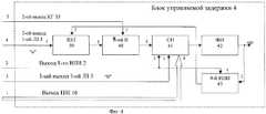
Блок управляемой задержки может быть выполнен по функциональной схеме, приведенной на фиг.4, содержащей общеизвестные элементы.Block controlled delay can be performed according to the functional diagram shown in figure 4, containing well-known elements.
Однако включение вновь введенных блоков в соответствии с вышеуказанными связями из общедоступных источников неизвестно, что позволяет сделать вывод о соответствии предлагаемого решения критерию «Новизна».However, the inclusion of newly introduced blocks in accordance with the above links from public sources is unknown, which allows us to conclude that the proposed solution meets the criterion of "Novelty."
При введении новых блоков в указанных связях с остальными блоками устройство проявляет новые свойства, позволяющие повысить точность измерения высоты полета летательного аппарата, что не следует из уровня техники и соответствует критерию «Изобретательский уровень».With the introduction of new blocks in these relationships with the rest of the blocks, the device exhibits new properties that can improve the accuracy of measuring the flight altitude of the aircraft, which does not follow from the prior art and meets the criterion of "Inventive step".
Сущность предлагаемого изобретения поясняется дальнейшим описанием и чертежами, на которых представлены:The essence of the invention is illustrated by a further description and drawings, which show:
- фиг.1 - функциональная схема прототипа;- figure 1 is a functional diagram of a prototype;
- фиг.2 - функциональная схема предлагаемого рециркуляционного радиовысотомера;- figure 2 is a functional diagram of the proposed recirculation radio altimeter;
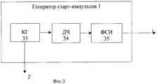
- фиг.3 - функциональная схема генератора старт-импульсов;- figure 3 is a functional diagram of a start-pulse generator;
- фиг.4 - функциональная схема блока управляемой задержки;- figure 4 is a functional diagram of a controlled delay unit;
- фиг.5 - функциональная схема следящей системы;- figure 5 is a functional diagram of a tracking system;
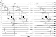
- фиг.6 - временные диаграммы, поясняющие работу РРВ в режиме измерения То;- Fig.6 is a timing chart explaining the operation of the RRV in the measurement mode Tabout ;
- фиг.7 - временные диаграммы, поясняющие работу РРВ в режиме измерения высоты.- Fig.7 is a timing diagram explaining the operation of the PPP in the mode of measuring height.
Функциональная схема рециркуляционного радиовысотомера приведена на фиг.2, на которой обозначены:Functional diagram of a recirculating radio altimeter is shown in figure 2, which indicates:
1 - генератор старт-импульсов (ГСИ);1 - start pulse generator (GSI);
2 - первый элемент ИЛИ (1-ый ИЛИ);2 - the first element OR (1st OR);
3 - первая линия задержки с отводом (1-ая ЛЗ);3 - the first delay line with tap (1st LZ);
4 - блок управляемой задержки (БУЗ);4 - block controlled delay (BUZ);
5 - вторая линия задержки (2-ая ЛЗ);5 - second delay line (2nd LZ);
6 - передатчик (Прд);6 - transmitter (Prd);
7 - направленный ответвитель (НО);7 - directional coupler (BUT);
8 - развязывающий блок (РБ);8 - decoupling unit (RB);
9 - антенный блок (АБ);9 - antenna unit (AB);
10 - детектор (Д);10 - detector (D);
11 - сверхвысокочастотный выключатель (СВЧВ);11 - microwave switch (microwave);
12 - третья линия задержки (3-я ЛЗ);12 - third delay line (3rd LZ);
13 - триггер (Т);13 - trigger (T);
14 - первый элемент И (1-ый И);14 - the first element of And (1st And);
15 - второй элемент И (2-ой И);15 - the second element And (2nd And);
16 - шифровальная колодка (ШК);16 - cipher block (ШК);
17 - приемник (Прм);17 - receiver (Prm);
18 - следящая система (СС);18 - tracking system (SS);
19 - разрешающий триггер (РТ);19 - enable trigger (RT);
20 - третий элемент И (3-ий И);20 - the third element of And (3rd And);
21 - четвертый элемент И (4-ый И);21 - the fourth element of And (4th And);
22 - счетчик числа периодов рециркуляции (СЧПР);22 - counter of the number of periods of recirculation (SCPR);
23 - пятый элемент И (5-ый И);23 - the fifth element of And (5th And);
24 - счетчик импульсов высоты (СИВ);24 - height pulse counter (SIV);
25 - оперативное запоминающее устройство (ОЗУ);25 - random access memory (RAM);
26 - вычитающее устройство (ВУ);26 - subtractive device (WU);
27 - преобразователь код-код (ПКК);27 - code-to-code converter (PAC);
28 - генератор тактовых импульсов (ГТИ);28 - clock generator (GTI);
29 - таймер;29 - timer;
30 - второй элемент ИЛИ (2-ой ИЛИ);30 - the second element OR (2nd OR);
31 - четвертая линия задержки (4-ая ЛЗ);31 - fourth delay line (4th LZ);
32 - третий элемент ИЛИ (3-ий ИЛИ);32 - the third element OR (3rd OR);
33 - шестой элемент И (6-ой И);33 - the sixth element And (6th And);
34 - инвертор;34 - inverter;
35 - седьмой элемент И (7-ой И).35 - the seventh element of And (7th And).
Связи между указанными блоками соответствуют приведенным на фиг.2.The relationship between these blocks correspond to those shown in figure 2.
Генератор старт-импульсов 1 (фиг.3) содержит:The start pulse generator 1 (figure 3) contains:
36 - кварцевый генератор (КГ);36 - crystal oscillator (KG);
37 - делитель частоты (ДЧ);37 - frequency divider (DF);
38 - формирователь старт-импульсов (ФСИ).38 - shaper start pulses (FSI).
Связи между указанными блоками соответствуют приведенным на фиг.3.The relationship between these blocks correspond to those shown in Fig.3.
Блок управляемой задержки 4 (фиг.4) содержит:Block controlled delay 4 (figure 4) contains:
39 - RS-триггер (RST);39 - RS-trigger (RST);
40 - восьмой элемент И (8-ой И);40 - the eighth element of And (8th And);
41 - счетчик импульсов (СИ);41 - pulse counter (SI);
42 - формирователь импульсов (ФИ);42 - pulse shaper (FI);
43 - четвертый элемент ИЛИ (4-ый ИЛИ).43 - the fourth element OR (4th OR).
Связи между указанными блоками соответствуют приведенным на фиг.4.The relationship between these blocks correspond to those shown in figure 4.
Следящая система 18 (фиг.5) содержит:The tracking system 18 (figure 5) contains:
44 - временной дискриминатор (ВД);44 - temporary discriminator (VD);
45 - фильтр нижних частот (ФНЧ);45 - low-pass filter (low-pass filter);
46 - временной модулятор (ВМ);46 - time modulator (VM);
47 - формирователь канала «Захват» (ФСЗ);47 - shaper channel "Capture" (FSZ);
48 - формирователь сигнала автоматической регулировки усиления (ФСАРУ).48 - shaper signal automatic gain control (FSARU).
Связи между указанными блоками соответствуют приведенным на фиг.5.The relationship between these blocks correspond to those shown in Fig.5.
На фиг.6 и фиг.7 представлены временные диаграммы, поясняющие принцип работы РРВ, соответственно в первом и втором режимах работы, а именно:In Fig.6 and Fig.7 presents time diagrams explaining the principle of operation of the PPP, respectively, in the first and second modes of operation, namely:
а - импульсы на выходе ГСИ 1;a - pulses at the output of
б - импульсы на 1-ом выходе 1-ой ЛЗ 3;b - pulses at the 1st output of the
в - импульсы на 2-ом выходе 1-ой ЛЗ 3;in - pulses on the 2nd output of the
г - импульсы на выходе RST 39;g - pulses at the output of
д - импульсы на выходе БУЗ 4;d - pulses at the output of the
е - импульсы на выходе 2-ой ЛЗ 5;e - pulses at the output of the
ж - импульсы на выходе триггера 13;g - pulses at the output of the
и - СВЧ-импульсы Прд 6;and - microwave pulses Prd 6;
к - импульсы на выходе Прм 17;k - pulses at the output of Prm 17;
л - импульсы на первом выходе СС 18;l - pulses at the first output of the SS 18;
м - импульсы на выходе Д 10;m - pulses at the output of
н - импульсы на выходе 3-ей ЛЗ 12;n - pulses at the output of the
о - импульсы на выходе 5-го И 23;about - pulses at the output of the 5th And 23;
п - импульсы на первом выходе 4-ой ЛЗ 31;p - pulses at the first output of the 4th LZ 31;
р - импульсы на втором выходе 4-ой ЛЗ 31;p - pulses at the second output of the 4th LZ 31;
с - импульсы на третьем выходе 4-ой ЛЗ 31;c - pulses at the third output of the 4th LZ 31;
т - импульсы на выходе РТ 19.t - pulses at the output of RT 19.
Генератор старт-импульсов 1, как и в прототипе, предназначен для обеспечения начала рециркуляции и должен формировать импульсы, период повторения которых должен быть существенно больше максимального периода рециркуляции в первом режиме, определяемого временами задержки, создаваемыми первой и второй линиями задержки, блоком управляемой задержки, передатчиком, приемником и следящей системой. ГСИ может быть выполнен, например, по функциональной схеме, приведенной на фиг.3. Формирование импульса «а» путем деления частоты КГ 36 обеспечивает отсутствие временных флюктуации импульса «д» на выходе БУЗ 4 относительно импульса «а».The start-
Первый элемент ИЛИ 2 обеспечивает прохождение импульсов, поступающих на его входы, на вход 1-ой ЛЗ 3 и второй вход триггера 13, и может быть выполнен в составе программируемой логической интегральной схемы (ПЛИС) типа ALTERA [13] или на микросхеме типа 1533.The first element OR 2 provides the passage of pulses arriving at its inputs, to the input of the
1-ая линия задержки 3 предназначена для формирования задержанных импульсов, необходимых для работы БУЗ 4, и может быть выполнена на ЛЗ типа ЛЗТ [15].The
Блок управляемой задержки 4 предназначен для формирования выходных импульсов, задержка которых относительно входных импульсов изменяется в соответствии с кодом, снимаемым с выхода ШК 16, и может быть выполнен по функциональной схеме, приведенной на фиг.4.The controlled
Вторая ЛЗ 5 предназначена для обеспечения задержки запуска Прд 6 относительно запуска СС 18, что необходимо для обеспечения измерения малых высот работы РРВ во втором режиме и для ограничения максимальной частоты повторения импульсов рециркуляции в первом режиме работы РРВ.The
В качестве 2-ой ЛЗ 5 может быть использована линия задержки типа ЛЗТ [15].As the
Передатчик 6 предназначен для формирования СВЧ импульсов малой длительности. Согласно [4], с.172, для измерения малых дальностей (высот) длительность зондирующих импульсов должна быть порядка десяти наносекунд. Такой передатчик может быть построен, как и в прототипе, на транзисторе типа 2Т982.The
Направленный ответвитель 7 предназначен для вывода части мощности СВЧ-колебаний, создаваемых Прд 6.
Развязывающий блок 8 предназначен для обеспечения работы Прд 6 на антенный блок 9 и пропускания поступающих на его вход-выход импульсов с выхода АБ 9 на вход Прм 17. В качестве РБ 8 может быть использован Y-циркулятор типа ФЦП2-13А.The decoupling unit 8 is designed to ensure the operation of
Антенный блок 9 предназначен для излучения импульсов СВЧ колебаний, создаваемых Прд 6, и приема сигналов, отраженных земной поверхностью. В качестве антенны может быть использована антенна обратной волны или параболическая антенна.
При использовании узконаправленных антенн в состав антенного блока могут входить устройства, обеспечивающие излучение сигналов по нормали к поверхности Земли по управляющим сигналам об углах крена и тангажа ЛА, поступающим с выхода системы управления, в состав которой входит РРВ.When using narrowly directed antennas, the antenna unit may include devices that provide radiation signals normal to the Earth's surface according to control signals about the angles of pitch and pitch of the aircraft, coming from the output of the control system, which includes the RRV.
Детектор 10 предназначен для создания видеоимпульса, соответствующего времени появления СВЧ-импульса Прд 6. В качестве диода детектора может быть использован диод 2А112.The
СВЧ-выключатель 11 предназначен для обеспечения прохождения СВЧ-импульса Прд 6 на вход Прм 17 при работе РРВ в первом режиме и уменьшения уровня этого сигнала при работе РРВ во втором режиме (режиме измерения высоты) и может быть выполнен на pin-диодах типа 2А543-А2.The
Третья линия задержки 12 предназначена для задержки импульса «м», снимаемого с выхода детектора Д10, и должна иметь время задержки tЛЗ3>tи,The
где tи - длительность излученного импульса.where tand is the duration of the emitted pulse.
При излучении наносекундных импульсов в качестве ЛЗ 3 возможно использование, как и в прототипе, короткого высокочастотного кабеля.When emitting nanosecond pulses as
Триггер 13 предназначен для создания импульса «ж», в течение действия которого затухание СВЧВ 11 минимально, и может быть выполнен на логических элементах ПЛИС.The
Первый элемент И 14 предназначен для пропускания импульса «д» на вход триггера 13 в первом режиме работы РРВ и может быть выполнен на логических элементах ПЛИС.The first element And 14 is designed to pass the pulse "d" to the input of the
Второй элемент И 15 предназначен для пропускания в первом режиме работы импульса «а» на первые входы 1-го элемента ИЛИ 2 и третьего элемента ИЛИ 32, который может быть выполнен в составе ПЛИС.The second element And 15 is designed to pass in the first mode of operation of the pulse "a" to the first inputs of the 1st element OR 2 and the third element OR 32, which can be made as part of the FPGA.
Шифровальная колодка 16 предназначена для преобразования кода, поступающего на нее со второго выхода СЧПР 22, что повышает имитоустойчивость РРВ, и может быть выполнена, как описано в [12].The encryption block 16 is designed to convert the code received from the second output of the MPS 22, which increases the resistance of the RRV, and can be performed as described in [12].
Приемник 17 предназначен для усиления и преобразования поступающих на его вход импульсов и может быть выполнен аналогично приемнику прототипа.The receiver 17 is designed to amplify and convert incoming pulses to its input and can be performed similarly to the receiver of the prototype.
Следящая система 18 предназначена для выделения отраженного сигнала на фоне помех и формирования поискового импульса «л», следящего за передним фронтом снимаемого с выхода приемника 17 импульса «к», формирования сигнала «Захват» при их совпадении, создания напряжения, регулирующего усиление приемника с целью обеспечения постоянной амплитуды импульса «к», снимаемого с его выхода, и может быть выполнена по схеме, приведенной на фиг.5, аналогичной используемой в [5].The tracking system 18 is designed to isolate the reflected signal against the background of noise and generate a search pulse “l” that monitors the leading edge of the “k” pulse taken from the output of the receiver 17, generate a “Capture” signal when they match, create a voltage that controls the gain of the receiver with the aim providing a constant amplitude of the pulse "k", taken from its output, and can be performed according to the circuit shown in figure 5, similar to that used in [5].
Разрешающий триггер 19 предназначен для формирования импульса, длительность которого пропорциональна времени рециркуляции в первом и втором режимах работы РРВ, и может быть выполнен на логических элементах, входящих в состав ПЛИС.The enable trigger 19 is designed to generate a pulse whose duration is proportional to the recirculation time in the first and second modes of operation of the RRV, and can be performed on the logic elements that make up the FPGA.
Третий элемент И 20 предназначен для пропускания импульсов ГТИ 28 на второй вход СИВ 24 по сигналу с выхода РТ 19 и может быть выполнен на логических элементах, входящих в состав ПЛИС.The third element And 20 is designed to transmit pulses of the GTI 28 to the second input of the SIV 24 by the signal from the output of the RT 19 and can be performed on the logical elements that make up the FPGA.
Четвертый элемент И 21 предназначен для пропускания поисковых импульсов «л» на 1-ый вход СЧПР 22 и на второй вход РТ 19 после захвата СС 18 импульса «к» с выхода Прм 17.The fourth element And 21 is designed to pass the search pulses "l" to the first input of the SCPR 22 and to the second input of the RT 19 after capturing the SS 18 pulse "k" from the output Prm 17.
Счетчик числа периодов рециркуляции 22 предназначен для счета числа периодов рециркуляции, выдачи информации о нем, поступающей на вход ШК 16, и выдачи сигнала лог.1, когда число периодов рециркуляции соответствует расчетному. Счетчик числа периодов рециркуляции может быть выполнен на логических элементах, входящих в состав ПЛИС.The counter of the number of recirculation periods 22 is intended for counting the number of recirculation periods, issuing information about it received at the input of the HQ 16, and issuing a signal log.1, when the number of recirculation periods corresponds to the calculated one. The counter of the number of recirculation periods can be performed on the logical elements that make up the FPGA.
Пятый элемент И 23 предназначен для пропуска на второй вход третьей ИЛИ 32 поискового импульса «л» после поступления на вход СЦПР 22 расчетного числа периодов рециркуляции.The fifth element And 23 is designed to pass to the second input of the third OR 32 of the search pulse "l" after receipt at the input of the SCR 22 of the estimated number of recirculation periods.
Счетчик импульсов высоты 24 предназначен для счета числа импульсов ГТИ 28, поступающих на его первый вход с выхода 3-го элемента И 20, и может быть выполнен на логических элементах, входящих в состав ПЛИС.The counter of pulses of height 24 is designed to count the number of pulses of the GTI 28 received at its first input from the output of the 3rd element And 20, and can be performed on the logical elements that make up the FPGA.
Оперативное запоминающее устройство 25 предназначено для записи в него кода времени То, полученного при работе РРВ в первом режиме, выдачи информации о То в ВУ 26 при работе ИРВ во втором режиме и может быть выполнено на микросхеме 556РТ5.The random access memory 25 is intended for recording into it a time code To obtained during the operation of the RRV in the first mode, issuing information about the To in the VU 26 during the operation of the RIR in the second mode and can be performed on the 556RT5 chip.
Вычитающее устройство 26 предназначено для вычитания запомненного в ОЗУ 25 кода времени То из кода времени Ти, полученного во втором режиме работы РРВ, и может быть выполнено на микросхемах 564ИМ-1.The subtractor 26 is designed to subtract the time code Tо stored in RAM 25 from the time code Tand obtained in the second mode of operation of the RRB, and can be performed on 564IM-1 microcircuits.
Преобразователь код-код 27 предназначен для преобразования параллельного кода, снимаемого с выхода ВУ 26, в код обмена, принятый в системе управления ЛА, в состав которой входит РРВ. Например, если обмен проводится по ГОСТ 26765.52-87, то в качестве ПКК-27 может быть использован малогабаритный приемопередатчик ВА996А, [10], с.14.The code-to-code converter 27 is intended for converting a parallel code taken from the output of the VU 26 into an exchange code adopted in the aircraft control system, which includes the RRV. For example, if the exchange is carried out according to GOST 26765.52-87, then the small-sized transceiver VA996A, [10], p.14, can be used as a PKK-27.
Генератор тактовых импульсов 28 предназначен для создания стабильных по частоте повторения импульсов, следующих с высокой частотой повторения, и может быть выполнен с использованием кварцевого резонатора, умножителя частоты и логических элементах, входящих в ПЛИС.The clock generator 28 is designed to create stable in frequency repetition of pulses following with a high repetition rate, and can be performed using a quartz resonator, a frequency multiplier and logic elements included in the FPGA.
Таймер 29 предназначен для периодического переключения РРВ из второго режима работы в первый с целью для определения время То задержки сигнала в цепях РРВ. Таймер может быть выполнен на логических элементах, входящих в ПЛИС.The timer 29 is designed to periodically switch the RRV from the second mode of operation to the first in order to determine the time Tabout the delay of the signal in the circuits of the RRV. The timer can be performed on the logical elements included in the FPGA.
Второй элемент ИЛИ 30 предназначен для подачи на 1-ый вход Т 13 импульсов «д» с выхода 1-го И 14 или импульсов «н» с выхода 3-ей ЛЗ 12.The second element OR 30 is designed to supply to the
Четвертая линия задержки 31 предназначена для задержки импульсов «а» или «о», формирования импульса «р», поступающего на первый вход РТ 19, импульса «п», поступающего на первый вход 6-го И 32 и второй вход 7-го И 35, и импульса «с», поступающего на вторые входы СЧПР 22 и СИВ 24.The fourth delay line 31 is designed to delay the pulses "a" or "o", the formation of the pulse "p" received at the first input of RT 19, the pulse "p" received at the first input of the 6th And 32 and the second input of the 7th And 35, and the pulse "c" supplied to the second inputs of the MFPR 22 and SIV 24.
Третий элемент ИЛИ 32 предназначен для пропускания на вход 4-й ЛЗ 31 импульсов «а» или импульсов «о».The third element OR 32 is designed to pass to the input of the 4th LZ 31 pulses "a" or pulses "o".
Шестой элемент И 33 предназначен для пропускания импульса «п» на первый вход ОЗУ 25 с целью записи в него информации о времени То в первом режиме работы РРВ.The sixth element And 33 is designed to transmit the pulse "p" to the first input of RAM 25 to record information about the time Tabout in the first mode of operation of the relay.
Инвертор 34 и седьмой элемент И 35 предназначены для пропускания импульса «п» во втором режиме работы РРВ на второй вход ОЗУ 25 с целью извлечения из него записанной в нем информации о времени То.The
Устройство работает в двух режимах:The device operates in two modes:
- первом, когда измеряется задержка То в цепях рециркуляции и приемопередатчика;- first, when the delay To is measured in the recirculation and transceiver circuits;
- втором, когда измеряется высота полета Нп.- second, when the flight altitude is measured Np .
Перевод в первый режим осуществляется таймером 29, формирующим при включении РРВ и в процессе его работы с некоторым периодом сигнал лог.1, поступающий на первые входы 1-го элемента И 14 и 2-го элемента И 15, второй вход 6-го элемента И 33 и инвертора 34.The transfer to the first mode is carried out by a timer 29, which forms a signal log.1, which is received at the first inputs of the 1st element And 14 and the 2nd element And 15, the second input of the 6th element And, when the RRV is turned on and during its operation with a
ГСИ 1 формирует импульсы «а», период повторения Т которых

где Tp1 - максимальный период повторения при работе в первом режиме;where Tp1 - the maximum repetition period when working in the first mode;
Тпоиска - время поиска;Tsearch - search time;
N - число рециркуляции.N is the number of recirculation.
Если, например, Tp1=15 мкс, N=32 и Тпоиска=500 мкс, то Т>980 мкс.If, for example, Tp1 = 15 μs, N = 32, and Tsearch = 500 μs, then T> 980 μs.
Эти импульсы через открытый 2-ой И 15 и первый элемент ИЛИ 2 поступают на 2-ой вход триггера 13 и приводят его в состояние лог.0, при котором СВЧВ 11 имеет большое затухание. Импульсы «а» с выхода 2-го И 15 через 3-ий ИЛИ 32 поступают также на вход 4-й ЛЗ 31. Снимаемый с ее второго выхода импульс «р» поступает на первый вход РТ 19, приводя его выход в состояние лог.0, при котором закрывается 3-й И 20, и импульсы ГСИ 28 не поступают на первый вход СИВ 24.These pulses through the open second AND 15 and the first element OR 2 are fed to the second input of the
Снимаемый с третьего выхода 4-й ЛЗ 31 импульс «с» поступает на вторые входы СИВ 24 и СЧПР 22, устанавливая в исходное состояние входящие в их триггеры.The pulse “s”, taken from the third output of the 4th LZ 31, is fed to the second inputs of the SIV 24 and SCPR 22, setting the triggers included in their initial state.
Импульсы «а» через 2-ой И 15 и 1-ый ИЛИ 2 поступают на вход 1-ой ЛЗ 3 и второй вход БУЗ 4, устанавливая входящие в состав СИ 41 триггеры (фиг.4) в нулевое положение. Импульсы «а» также через 4-ый ИЛИ 43 поступают на второй вход RST 39, устанавливая его в положение лог.0, при котором 8-ой И 40 закрыт.The pulses "a" through the 2nd AND 15th and 1st OR 2 are fed to the input of the
Снимаемый с первого выхода 1-ой ЛЗ 3 импульс «б» вводит в триггеры СИ 41 код с выхода ШК 16.Pulse “b”, taken from the first output of the
Импульс «в» со второго выхода 1-ой ЛЗ 3 поступает на первый вход RST 39 и переводит его в состояние лог.1, при котором открывается 8-ой И 40, и поступающие на его второй вход импульсы КГ 36 начинают поступать на первый вход СИ 41. После заполнения СИ 41 на его выходе возникает перепад напряжения, который запускает ФИ 42, формирующий импульс «д», переводящий RST 39 через 4-ый ИЛИ 43 в состояние лог.0.The pulse "in" from the second output of the
Таким образом, время задержки τ3 импульса «д» относительно импульса «в» будет изменяться в зависимости от кода, поступающего с выхода ШК 16. Чем большее значение кода поступает на БУЗ 4, тем меньше τ3. Этим самым обеспечивается рециркуляция с изменяющимся периодом повторения с одним и тем же законом изменения как в режиме измерения То, так и в режиме измерения высоты.Thus, the delay time τ3 of the pulse "d" relative to the pulse "in" will vary depending on the code coming from the output of the HF 16. The larger the value of the code arrives at
Импульс «д» поступает на вход 2-ой ЛЗ 5, 1-ый вход СС 18 и второй вход 1-го И 14. Поскольку на его первый вход (фиг.2) в этом режиме подается уровень лог.1, импульс «д» проходит на его выход, через второй элемент ИЛИ 30 поступает на первый вход триггера 13 и переводит его выход в состояние лог.1, при котором затухание СВЧВ 11 мало. Снимаемые с выхода 2-ой ЛЗ 5 импульсы «е» запускают ПРД 6, формирующий импульсы «и» СВЧ колебаний, которые ослабляются на величину развязки между первым входом и вторым выходом РБ 8 и через второй выход РБ 8 и СВЧВ 11 поступают на вход Прм 17, усиливаются и преобразуются им в импульсы «к», поступающие на второй вход СС 18, ВМ 46 которой формирует поисковый импульс «л», задержка которого относительно импульса «д», поступающего на его второй вход, увеличивается до тех пор, пока его задний фронт не совпадает с передним фронтом импульса «к». После совпадения нескольких импульсов «л» с импульсами «к» на выходе ВД 44 следящей системы 18 (фиг.5) появляется напряжение, переводящее СС 18 в режим слежения за импульсом «к». Поскольку отраженные от Земли импульсы приходят на второй выход РБ 8 после импульсов «и», а СС 18 осуществляет поиск начиная с минимальной задержки, захват этих импульсов не происходит. Под действием этого напряжения срабатывает ФСЗ 47, и СС 18 на втором выходе формирует сигнал «Захват» в виде уровня лог.1, поступающий на вторые входы 4-го И 21 и 5-го И 23, обеспечивая тем самым поступление поискового импульса «л» на первый вход СЧПР 22, и на второй вход РТ 19, переводя его в состояние лог.1, при котором 3-й И 20 открывается по первому входу, и импульсы ГСИ 28 начинают поступать на 1-й вход СИВ 24.The pulse "d" is fed to the input of the
Поисковый импульс «л» поступает также на второй вход 1-го ИЛИ 2, переводит триггер 13 в состояние лог.0 и через 1-ю ЛЗ 3 поступает на вход БУЗ 4, формирующий импульс «д», который через 2-ю ЛЗ 5 запускает Прд 6.The search impulse “l” also arrives at the second input of the 1st OR 2, puts the
Таким образом, при работе в первом режиме рециркуляция происходит с периодом TpiThus, when operating in the first mode, recirculation occurs with a period Tpi

где tЛЗ1, tЛЗ2, tБУЗ4i, tпрд, tпр, tcc - время задержки сигнала, создаваемое первой и второй линиями задержки, блоком управляемой задержки, передатчиком, приемником и следящей системой, соответственно.where tLZ1 , tLZ2 , tBUZ4i , tprd , tpr , tcc is the signal delay time created by the first and second delay lines, a controlled delay unit, a transmitter, a receiver, and a tracking system, respectively.
При этом время задержки tБУЗ 4i изменяется в зависимости от кода, поступающего на его 1-ый вход и представляющего собой модифицируемый ШК 16 код с выхода СЧПР 22.In this case, the delay time tBUZ 4i varies depending on the code received at its first input and which is a modifiable bar code 16 from the output of the SCPR 22.
Если, например, tЛЗ 1=1 мкс, tБУЗ 4i=15 мкс, tЛЗ 2=0,5 мкс, tпрд=0,1 мкс, tпр=0,5 мкс, tcc=0,5 мкс, то Тpi=1+15+0,5+0,1+0,5+0,1=17,2 мкс.If, for example, t1 =LZ 1 microsecond, tBUZ 4i = 15 ms, t2 LZ = 0.5 ms, t = 0.1 msTx, tave = 0.5 microseconds, t = 0.5 microsecondscc , then Tpi = 1 + 15 + 0.5 + 0.1 + 0.5 + 0.1 = 17.2 μs.
После осуществления N периодов рециркуляции на первом выходе СЧПР 22 возникает сигнал лог.1, открывающий 5-й И 23, на выходе которого возникает импульс «о», поступающий через второй вход 3-го ПЛИ 32 на вход 4-й ЛЗ 31. Снимаемый с ее второго выхода импульс «р» задержан относительно импульса «о» на времяAfter the implementation of N periods of recirculation at the first output of the control system 22 there is a signal log.1, opening the 5th And 23, the output of which there is a pulse "o", coming through the second input of the 3rd PLI 32 to the input of the 4th LZ 31. Removed from its second output, the pulse "p" is delayed relative to the pulse "o" for a time

где tПИ - длительность поискового импульса «л».where tPI - the duration of the search pulse "l".
Импульс «р» поступает на первый вход РТ 19, переводя его в состояние лог.0, при котором 3-ий И 20 закрыт.The pulse "p" arrives at the first input of RT 19, translating it into a state of log.0, in which the 3rd And 20 is closed.
Очевидно, что время Т0, в течение которого 3-ий И 20 находился в открытом состоянии при работе РРВ в первом режиме, составляет:It is obvious that the time T0 , during which the 3rd And 20 was in the open state when the RRV in the first mode, is:

где tБУЗ4i - время задержки, создаваемое БУЗ 4 в i-том периоде повторения;where tBUZ4i is the delay time created by
tЗ1ЛЗ31 - время задержки импульса «р» относительно импульса «о».tЗ1ЛЗ31 - delay time of the pulse "p" relative to the pulse "o".
В течение этого времени в СИВ 24 будут поступать импульсы ГТИ 28, и на его выходе формируется параллельный код, соответствующий этому времени.During this time, GTI pulses 28 will arrive at SIV 24, and a parallel code corresponding to this time will be generated at its output.
Снимаемый с 1-го выхода 4-й ЛЗ 31 импульс «п» поступает на 1-ые входы 6-го И 33 и 7-го И 35. При этом время задержки импульса «п» относительно импульса «р» должно быть больше времени установления триггеров СИВ 24.Pulse “p” taken from the 1st output of the 4th LZ 31 is fed to the 1st inputs of the 6th And 33th and 7th And 35. In this case, the delay time of the pulse “p” relative to the pulse “p” should be longer establishing triggers SIV 24.
Поскольку открыт только 6-ой И 33, импульс «п» проходит на его выход, поступает на 3-ий вход ОЗУ 25 и осуществляет запись в него кода с выхода СИВ 24.Since only the 6th And 33 is open, the pulse "p" goes to its output, goes to the 3rd input of RAM 25 and writes the code to it from the output of SIV 24.
Снимаемый с выхода 5-го И 23 импульс «о» поступает на вход таймера 29, который формирует на своем выходе уровень лог.0. Снимаемый с третьего выхода ЛЗ 31 импульс «с» поступает на 2-ые входы СЧПР 22 и СИВ 24, устанавливая входящие в их триггеры в состояние лог.0, и РРВ переводится в режим измерения высоты.The “o” pulse removed from the output of the 5th And 23 is fed to the input of a timer 29, which forms a level of log.0 at its output. The pulse “s”, taken from the third output of LZ 31, is fed to the 2nd inputs of the SCHPR 22 and SIV 24, setting the triggers entering their triggers in the state of log.0, and the RRV is switched to the height measurement mode.
Число рециркуляции N выбирается исходя из допустимой флюктуационной погрешности измерения высоты, определяемой какThe recirculation number N is selected based on the permissible fluctuation error of the height measurement, defined as

где fкв - частота генератора ГТИ 28.where fkv is the frequency of the GTI generator 28.
Откуда
Максимальная частота tкв ограничивается быстродействием счетных триггеров СИ 41. Как показано в [14], триггер Мах 9381 может считать импульсы, следующие с частотой 3 ГГц.The maximum frequency tkv is limited by the speed of the SI 41 counting triggers. As shown in [14], the Max 9381 trigger can count pulses following with a frequency of 3 GHz.
Если считать, что tкв=109 Гц, σф=3·10-3 м,If we assume that tsquare = 109 Hz, σf = 3 · 10-3 m,
тоthen

Для удобства приборной реализации следует выбрать N=32.For the convenience of instrumentation, you should choose N = 32.
Время T1, необходимое для измерения времени То, можно определить какThe time T1 required to measure the time To can be defined as

Если, например, Тр1=17,6 мкс, а N=32, Тпоиска=0,5 мс, то T1=1 мс.If, for example, Tp1 = 17.6 μs, and N = 32, Tsearch = 0.5 ms, then T1 = 1 ms.
Такое малое время позволяет производить измерение времени То и в процессе полета ЛА, поскольку возможное изменение высоты полета ΔНЛА ЛА за это время мало и составляетSuch a short time allows the measurement of the time To and during the flight of the aircraft, since the possible change in flight altitude ΔНLA of the aircraft during this time is small and amounts to

где Vв = вертикальная скорость ЛА.where Vin = the vertical speed of the aircraft.
Если даже принять Vв=100 м/с, то ΔНЛА=100·1·10-3=0,1 м.Even if we take Vin = 100 m / s, then ΔНЛА = 100 · 1 · 10-3 = 0.1 m.
В прототипе частота генератора тактовых импульсов, определяемая быстродействием процессорного блока, составляет fпр=12 МГц.In the prototype, the frequency of the clock generator, determined by the speed of the processor unit, is fCR = 12 MHz.
Следовательно, число рециркуляции в прототипе Nпр должно быть увеличено в

а Т1ПР=Тp1·Nпр+Тпоиска=17,6·10-6·2,66·103+0,5·10-3=47,4 мкс.and T1PR = Tp1 · Npr + Tsearch = 17.6 · 10-6 · 2.66 · 103 + 0.5 · 10-3 = 47.4 μs.
Поэтому при тех же условиях полетаTherefore, under the same flight conditions

что в ряде случаев недопустимо.which in some cases is unacceptable.
При работе в режиме измерения высоты с выхода таймера 29 снимается уровень лог.0, первый элемент И 14 и второй элемент И 15 закрыты, следовательно, импульсы «а» не проходят на выход 2-го И 15, а импульсы «д» не проходят на выход 1-го И 14. Поэтому триггер 13 в момент излучения импульсов «и» находится в состоянии лог.0, при котором затухание СВЧВ 11 велико, уровень зондирующего сигнала на выходе Прм 17 ниже порога его чувствительности, и захват его СС 18 не происходит. Снимаемые с выхода 2-ой ЛЗ 5 импульсы «е» запускают Прд 6, импульсы СВЧ-колебаний которого через НО 7 и РБ 8 подводятся к АБ 9 и излучаются. Снимаемые со второго выхода НО 7 СВЧ-колебания детектируются Д 10 и через 3-ю ЛЗ 12 и 2-ой вход второго ИЛИ 30 поступают на 1-ый вход триггера 13, переводя его в состояние лог.1, при котором затухание СВЧВ 11 минимально, что обеспечивает прохождение на вход Прм 17 сигналов, отраженных земной поверхностью и принятых антенным блоком 9. Эти сигналы усиливаются и преобразуются Прм 17, поступают на 2-ой вход СС 18 и обрабатываются так же, как и сигналы передатчика 6, принятые в первом режиме, т.е. сначала РРВ находится в режиме поиска, триггеры СИВ 24 и СЧПР 22 приведены в нулевое состояние, РТ 19 - в состояние лог.0.When operating in the height measurement mode, the output level 0 is taken from the output of timer 29, the first element And 14 and the second element And 15 are closed, therefore, the pulses "a" do not pass to the output of the 2nd And 15, and the pulses "d" do not pass to the output of the 1st And 14. Therefore, the
После совпадения импульсов «к» и «л» СС 18 на втором выходе создает сигнал «Захват», ФСАРУ формирует напряжение автоматической регулировки усиления (АРУ), поддерживающее постоянную амплитуду импульса «к», РТ 19 переводится в состояние лог.1 импульсом «л», снимаемым с выхода 4-го И 21; после осуществления N рециркуляций на выходе 5-го И 23 возникает импульс «о», поступающий через 2-ой вход 3-го ИЛИ 32 на 4-ю ЛЗ 31.After the pulses “k” and “l” coincide, the SS 18 generates a “Capture” signal at the second output, the FSARU generates an automatic gain control voltage (AGC) that maintains a constant amplitude of the “k” pulse, RT 19 is put into log.1 state by the “l” pulse "Removed from the exit of the 4th And 21; after N recirculation occurs at the output of the 5th AND 23, an impulse “o” arises, coming through the 2nd input of the 3rd OR 32 to the 4th LZ 31.
При работе в этом режиме рециркуляция происходит с периодомWhen operating in this mode, recirculation occurs with a period

Очевидно, что время Т`и, в течение которого 3-ий И 20 находился в открытом состоянии при работе РРВ во втором режиме, составляет:It is obvious that the time T`and , during which the 3rd And 20 was in the open state during the operation of the RRV in the second mode, is:

На выходе СИВ 24 формируется код, определяемый временами То и
где Н - высота полета ЛА;where N is the flight altitude of the aircraft;
С - скорость света,C is the speed of light
т.е. измеряется tи=То+Тh.those. measured tand = Tabout + Th .
Этот код подается на второй вход ВУ 26, на первый вход которого подается код с выхода ОЗУ 25. Так как в этом режиме напряжение на выходе таймера 29 равно нулю, то импульс «п» проходит на выход 7-го И 35, поступает на первый вход ОЗУ 25 и извлекает из него код ранее записанного времени То, который подается на первый вход ВУ 26.This code is fed to the second input of the VU 26, to the first input of which a code is supplied from the output of the RAM 25. Since in this mode the voltage at the output of the timer 29 is zero, the pulse "p" goes to the output of the 7th And 35th, goes to the first the input of RAM 25 and extracts from it the code of the previously recorded time Tabout , which is fed to the first input of the VU 26.
ВУ 26 проводит вычитание, и на его выходе формируется параллельный код времени tи=То+Тh-То=Тh.WU 26 carries out the subtraction, and at its output a parallel code of time tand = То + Тh -То = Тh is formed .
Таким образом, выходной код ВУ 26 содержит информацию только о времени Тh. Этот код преобразуется ПКК 27 в код, принятый в системе управления ЛА, в которую входит РРВ.Thus, the output code WU 26 contains information only about the time Th . This code is converted by the GAC 27 into the code adopted in the aircraft control system, which includes the RRV.
Погрешность измерения высоты определяется удвоенной величиной ошибки дискретности σq, определяемой частотой генератора fкв и числом рециркуляции N.The error in measuring the height is determined by the double value of the discreteness error σq , determined by the frequency of the generator fsq and the number of recirculation N.
Если принять fкв=109 Гц, N=32, то σq=3·10-3 м, а ΔН=6·10-3 м, т.е. ошибка близка к погрешности уровнемера [6] и на несколько порядков меньше ошибки ИРВ А-035 [5].If we take fq = 109 Hz, N = 32, then σq = 3 · 10-3 m, and ΔН = 6 · 10-3 m, i.e. the error is close to the error of the level gauge [6] and is several orders of magnitude smaller than the error of the IRV A-035 [5].
При этом время обновления информации о высоте полета
Если, например, N=32, То=17 мкс и Н=10 км, то
Это время значительно меньшее времени обновления информации как в прототипе, так и в изделии А-035, в котором это время может достигать 50 мс.This time is much shorter than the update time of the information both in the prototype and in the product A-035, in which this time can reach 50 ms.
Вновь вводимые блоки: развязывающий блок и направленный ответвитель имеют малые затухания (менее 1,5 дБ) и не приведут к значительным снижениям излучаемой мощности и чувствительности приемника.Newly introduced units: the decoupling unit and the directional coupler have small attenuation (less than 1.5 dB) and will not lead to significant reductions in radiated power and receiver sensitivity.
Для построения заявляемого РВ может быть использована элементная база, выпускаемая, в основном, в настоящее время отечественной промышленностью.To build the inventive RV can be used elemental base, produced mainly in the present domestic industry.
Вновь введенные генератор тактовых импульсов, разрешающий триггер, элементы И, ИЛИ, счетчики импульсов, таймер, могут быть выполнены в виде одной программируемой логической интегральной схемы, а детектор, развязывающий блок и направленный ответвитель могут быть изготовлены по тонкопленочной технологии.The newly introduced clock generator, enabling trigger, AND, OR elements, pulse counters, timer, can be made in the form of one programmable logic integrated circuit, and the detector, the decoupling unit and the directional coupler can be made using thin-film technology.
Следовательно, введение дополнительных блоков не приведет к значительному увеличению объема и массы по сравнению с прототипом.Therefore, the introduction of additional blocks will not lead to a significant increase in volume and mass compared to the prototype.
Работа РРВ на одну антенну при использовании СВЧ-импульсов наносекундной деятельности позволяет измерять малые высоты полета ЛА и исключить методическую ошибку измерения высоты применяемых ИРВ, работающих на две антенны (передающую и приемную). Эта ошибка может достигать 0,68 м [20].The operation of the RRS on one antenna when using microwave pulses of nanosecond activity allows one to measure small aircraft altitudes and eliminate the methodological error in measuring the altitude of the applied RIR operating on two antennas (transmitting and receiving). This error can reach 0.68 m [20].
Между тем, в последнее время рядом заказчиков РВ выдвигаются требования повышения точности измерения малых высот. Например, в [17] изложено требование к измерения высот полета ЛА от 0 до 5 м с погрешностью менее ±0,1 м, а в [18] - высот до 100 м с погрешностью менее ±(0,2+1% Н) м, в то время как лучший РВ последней разработки (А052 [19]) измеряет малые высоты с погрешностью 2σ=±(0,45+1% Н) м.Meanwhile, recently, a number of RV customers have put forward requirements for improving the accuracy of measuring small heights. For example, in [17] a requirement was stated for measuring aircraft altitudes from 0 to 5 m with an error of less than ± 0.1 m, and in [18] - heights of up to 100 m with an error of less than ± (0.2 + 1% N) m, while the best RV of the latest design (A052 [19]) measures small heights with an error of 2σ = ± (0.45 + 1% N) m.
Поэтому предлагаемый РРВ может найти применение для точного измерения высоты, в том числе и для проверки точности вновь разрабатываемых РВ различного назначения, и, следовательно, удовлетворяет требованию критерия «Промышленная применимость».Therefore, the proposed RRV can be used for accurate height measurement, including for checking the accuracy of newly developed RVs for various purposes, and, therefore, satisfies the requirement of the criterion of "Industrial applicability".
ЛитератураLiterature
1. Рециркуляционный радиовысотомер. Авторское свидетельство СССР №326528 от 22.10.1971 по заявке №1411131/26-9 от 2.03.1970, кл. G 01 S 9/10.1. Recirculation radio altimeter. USSR copyright certificate No. 326528 of 10.22.1971 on application No. 1411131 / 26-9 of 2.03.1970, class. G 01
2. Викторов В.А., Лункин Б.В., Совлухов А.С. Высокочастотный метод измерения неэлектрических величин. - М.: Наука, 1973, с.72, с.150, с.132.2. Viktorov V.A., Lunkin B.V., Sovlukhov A.S. High-frequency method for measuring non-electric quantities. - M .: Nauka, 1973, p. 72, p. 150, p. 132.
3. Радиолокационные системы летательных аппаратов. Под ред. П.С.Давыдова. - М.: Транспорт, 1977, с.220.3. Radar systems of aircraft. Ed. P.S.Davydova. - M.: Transport, 1977, p. 220.
4. Моругин Л.А. Импульсные устройства с запаздывающей обратной связью. - М.: Советское радио, 1961. с.172.4. Morugin L.A. Impulse devices with delayed feedback. - M.: Soviet Radio, 1961.p.172.
5. Изделие А-035. Руководство по технической эксплуатации ГУ 1.000.048 РЭ. УПКБ «Деталь», г.Каменск-Уральский, 1988.5. Product A-035. Guidance on the technical operation of GU 1.000.048 OM. UPKB "Detail", Kamensk-Uralsky, 1988.
6. Радиолокационный импульсный рециркуляционный уровнемер. Патент РФ №2176382, кл. G 01 F 23/00 от 27.11.2001 по заявке №2000117976 от 5.07.2000 г.6. Radar pulsed recirculation level gauge. RF patent No. 2176382, cl. G 01 F 23/00 of 11/27/2001 according to the application No.2000117976 of 07/05/2000
7. Микроэлектронные устройства СВЧ. Под ред. Г.И.Веселова. - М.: Высшая школа, 1988, с.57-58.7. Microelectronic microwave devices. Ed. G.I. Veselova. - M.: Higher School, 1988, p. 57-58.
8. Вайсблат А.В. Коммутационные устройства СВЧ на полупроводниковых диодах. - М.: Радио и связь, 1987, с.50-72.8. Weissblat A.V. Microwave switching devices on semiconductor diodes. - M.: Radio and Communications, 1987, p. 50-72.
9. Титце У., Шенк К. Полупроводниковая схемотехника. - М.: Мир, 1982, с.102, 117-121, 331-338, 344-350, 392.9. Titz U., Schenk K. Semiconductor circuitry. - M .: Mir, 1982, p.102, 117-121, 331-338, 344-350, 392.
10. Аксесуары для построения линий передачи информации MIL STD-1553В и приборы для их отладки. Рекламный проспект фирмы «ЭЛКУС», 2004, с.14.10. Accessories for building information transmission lines MIL STD-1553В and devices for debugging them. Advertising brochure of the company "ELKUS", 2004, p.14.
11. Митяшев Б.Н. Определение временного положения импульса при наличии помех. - М.: Советское радио, 1962, с.39.11. Mityashev B.N. Determination of the temporary position of the pulse in the presence of interference. - M .: Soviet Radio, 1962, p. 39.
12. Система опознавания «свой-чужой». Патент РФ №2191403 по заявке 2001133283/09 от 11.12.2001, кл. G 01 S 13/78, 13/74.12. The recognition system "friend or foe." RF patent No. 2191403 on the application 2001133283/09 from 12/11/2001, cl. G 01
13. WWW.ALTERA.com.13. WWW.ALTERA.com.
14. Триггер Max 9381. WWW maxim ic.com.14. Trigger Max 9381. WWW maxim ic.com.
15. Линии задержки теплостойкие типа ЛЗТ. Технические условия ГИО.206.004 ТУ, 1986.15. Delay lines heat-resistant type LZT. Specifications GIO.206.004 TU, 1986.
16. Жуковский А.П., Оноприенко Е.И., Чижов В.И. Теоретические основы радиовысотометрии. - М.: Советское радио, 1979, с.145-147.16. Zhukovsky A.P., Onoprienko E.I., Chizhov V.I. Theoretical foundations of radio altimetry. - M .: Soviet Radio, 1979, p.145-147.
17. Письмо Авиационного научно-технического комплекса «Антонов» от 14.10.2000, исх. 12/7676.17. Letter from the Antonov Aviation Scientific and Technical Complex dated 10.10.2000, ref. 12/7676.
18. Техническое задание на разработку импульсного радиовысотомера. Раменское приборостроительное конструкторское бюро, исх. 287/102 от 09.02.2004.18. Terms of reference for the development of a pulsed radio altimeter. Ramenskoe instrument-making design bureau, ref. 287/102 dated 02/09/2004.
19. Малогабаритные авиационные радиовысотомеры А-052, А-053. Рекламный проспект ОАО «Уральское проектно-конструкторское «Деталь», 2004.19. Small-sized aviation radio altimeters A-052, A-053. Advertising brochure of OJSC "Ural Design and Development" Detail ", 2004.
20. Жуков В.М., Жуков М.В. Способ измерения радиовысотомером малых и предельно малых высот. Заявка на предполагаемое изобретение №2004113049 от 27.04.2004.20. Zhukov V.M., Zhukov M.V. A method of measuring a radio altimeter of small and extremely small heights. Application for the alleged invention No. 2004113049 dated 04/27/2004.
Claims (1)
Translated fromRussianPriority Applications (1)
| Application Number | Priority Date | Filing Date | Title |
|---|---|---|---|
| RU2004124672/09ARU2273862C1 (en) | 2004-08-12 | 2004-08-12 | Recycling radio altimeter |
Applications Claiming Priority (1)
| Application Number | Priority Date | Filing Date | Title |
|---|---|---|---|
| RU2004124672/09ARU2273862C1 (en) | 2004-08-12 | 2004-08-12 | Recycling radio altimeter |
Publications (2)
| Publication Number | Publication Date |
|---|---|
| RU2004124672A RU2004124672A (en) | 2006-01-27 |
| RU2273862C1true RU2273862C1 (en) | 2006-04-10 |
Family
ID=36047600
Family Applications (1)
| Application Number | Title | Priority Date | Filing Date |
|---|---|---|---|
| RU2004124672/09ARU2273862C1 (en) | 2004-08-12 | 2004-08-12 | Recycling radio altimeter |
Country Status (1)
| Country | Link |
|---|---|
| RU (1) | RU2273862C1 (en) |
Cited By (3)
| Publication number | Priority date | Publication date | Assignee | Title |
|---|---|---|---|---|
| RU2519914C2 (en)* | 2012-09-04 | 2014-06-20 | Федеральное государственное автономное образовательное учреждение высшего профессионального образования "ЮЖНЫЙ ФЕДЕРАЛЬНЫЙ УНИВЕРСИТЕТ" | Pulse radar altimeter |
| RU2519911C2 (en)* | 2012-09-04 | 2014-06-20 | Федеральное государственное автономное образовательное учреждение высшего профессионального образования "ЮЖНЫЙ ФЕДЕРАЛЬНЫЙ УНИВЕРСИТЕТ" | Recirculating radar altimeter |
| RU2519952C2 (en)* | 2012-09-04 | 2014-06-20 | Федеральное государственное автономное образовательное учреждение высшего профессионального образования "ЮЖНЫЙ ФЕДЕРАЛЬНЫЙ УНИВЕРСИТЕТ" | Radar altimeter with frequency-modulated sounding signal |
Citations (5)
| Publication number | Priority date | Publication date | Assignee | Title |
|---|---|---|---|---|
| US4276549A (en)* | 1978-12-26 | 1981-06-30 | U.S. Philips Corporation | FM-CW Radar distance measuring apparatus |
| US4733239A (en)* | 1984-02-27 | 1988-03-22 | Schmitt Jerry C | Radar altimeter |
| RU2106655C1 (en)* | 1996-06-17 | 1998-03-10 | Уральское проектно-конструкторское бюро "Деталь" | Frequency-modulated altimeter |
| RU2133483C1 (en)* | 1998-04-21 | 1999-07-20 | Уральское проектно-конструкторское бюро "Деталь" | Frequency-modulated altimeter |
| RU2176382C1 (en)* | 2000-07-05 | 2001-11-27 | ГУП Уральское проектно-конструкторское бюро "Деталь" | Radar pulse recirculation level indicator |
- 2004
- 2004-08-12RURU2004124672/09Apatent/RU2273862C1/enactive
Patent Citations (5)
| Publication number | Priority date | Publication date | Assignee | Title |
|---|---|---|---|---|
| US4276549A (en)* | 1978-12-26 | 1981-06-30 | U.S. Philips Corporation | FM-CW Radar distance measuring apparatus |
| US4733239A (en)* | 1984-02-27 | 1988-03-22 | Schmitt Jerry C | Radar altimeter |
| RU2106655C1 (en)* | 1996-06-17 | 1998-03-10 | Уральское проектно-конструкторское бюро "Деталь" | Frequency-modulated altimeter |
| RU2133483C1 (en)* | 1998-04-21 | 1999-07-20 | Уральское проектно-конструкторское бюро "Деталь" | Frequency-modulated altimeter |
| RU2176382C1 (en)* | 2000-07-05 | 2001-11-27 | ГУП Уральское проектно-конструкторское бюро "Деталь" | Radar pulse recirculation level indicator |
Cited By (3)
| Publication number | Priority date | Publication date | Assignee | Title |
|---|---|---|---|---|
| RU2519914C2 (en)* | 2012-09-04 | 2014-06-20 | Федеральное государственное автономное образовательное учреждение высшего профессионального образования "ЮЖНЫЙ ФЕДЕРАЛЬНЫЙ УНИВЕРСИТЕТ" | Pulse radar altimeter |
| RU2519911C2 (en)* | 2012-09-04 | 2014-06-20 | Федеральное государственное автономное образовательное учреждение высшего профессионального образования "ЮЖНЫЙ ФЕДЕРАЛЬНЫЙ УНИВЕРСИТЕТ" | Recirculating radar altimeter |
| RU2519952C2 (en)* | 2012-09-04 | 2014-06-20 | Федеральное государственное автономное образовательное учреждение высшего профессионального образования "ЮЖНЫЙ ФЕДЕРАЛЬНЫЙ УНИВЕРСИТЕТ" | Radar altimeter with frequency-modulated sounding signal |
Also Published As
| Publication number | Publication date |
|---|---|
| RU2004124672A (en) | 2006-01-27 |
Similar Documents
| Publication | Publication Date | Title |
|---|---|---|
| CN105793677B (en) | Adaptive Radar System with Multiple Waveforms | |
| US8031108B2 (en) | Pulse radar ranging system | |
| EP3077777B1 (en) | Multi-mode pulsed radar providing automatic transmit pulse signal control | |
| US5115242A (en) | In-furnace slag level measuring apparatus | |
| US3969725A (en) | Distance measuring equipment | |
| RU2412450C2 (en) | Method of reducing lower boundary of low altitude measurement to zero and design of coherent impulse doppler radioaltimetre to this end | |
| CN104730502B (en) | A kind of pulse regime radio altimeter arbitrary height analogue means | |
| US9031811B2 (en) | System and method for pulse-echo ranging | |
| CN108139260B (en) | Method for measuring the level of a filling substance located in a container | |
| CN103608694A (en) | Analog baseband circuit for terahertz phased array system | |
| US11686833B2 (en) | Method for radar ranging and transceiver therefor | |
| US20100201408A1 (en) | Digital Time Base Generator and Method for Providing a First Clock Signal and a Second Clock Signal | |
| US9329072B2 (en) | Receiver with programmable gain for UWB radar | |
| US7633434B2 (en) | Pulse radar system with a signal integration device having a sample and hold circuit | |
| Tang et al. | A delay-correlating direct-sequence spread-spectrum (DS/SS) radar system-on-chip operating at 183–205 GHz in 28 nm CMOS | |
| RU2273862C1 (en) | Recycling radio altimeter | |
| CN204405834U (en) | A kind of pulse regime radio altimeter arbitrary height analogue means | |
| KR20200068586A (en) | Impulse radar transceiver for compensating path loss | |
| CN100504436C (en) | A Radar Altimeter for On-orbit Detection and Landing | |
| RU2336540C1 (en) | Altitude radiosensor | |
| RU2258943C1 (en) | Pulse radio height meter | |
| Pecovsky et al. | 15 th order m-sequence soc radar for short-range sensing | |
| RU2282211C2 (en) | Radar pulse re-circulation radio altimeter | |
| Gong et al. | Design and application of the digital multifunctional ionosonde | |
| RU2247950C1 (en) | Radiolocation pulse recirculation level meter |