RU2269205C1 - Device for resolving radio-pulse signals in random noise background - Google Patents
Device for resolving radio-pulse signals in random noise backgroundDownload PDFInfo
- Publication number
- RU2269205C1 RU2269205C1RU2004120665/09ARU2004120665ARU2269205C1RU 2269205 C1RU2269205 C1RU 2269205C1RU 2004120665/09 ARU2004120665/09 ARU 2004120665/09ARU 2004120665 ARU2004120665 ARU 2004120665ARU 2269205 C1RU2269205 C1RU 2269205C1
- Authority
- RU
- Russia
- Prior art keywords
- unit
- input
- output
- block
- outputs
- Prior art date
Links
Images


Landscapes
- Radar Systems Or Details Thereof (AREA)
Abstract
Description
Translated fromRussianИзобретение относится к технике электросвязи и может быть использовано в приемниках сигналов радиоуправления, радиолокационных станций, систем связи с подвижными объектами.The invention relates to telecommunication technology and can be used in receivers of radio signals, radar stations, communication systems with mobile objects.
В качестве аналога выбрано устройство для подавления шума в системе связи (патент РФ RU 2169992 С2 "Способ и устройство для подавления шума в системе связи", опубл. 27.06.2001), которое предназначено для передачи информации с использованием информационных кадров в каналах, причем информационные кадры содержат шум, из которого получают оценку шума канала, при этом устройство содержит средство для оценки энергии канала в текущем информационном кадре, средство для оценки полной энергии канала в текущем информационном кадре на основе оценки энергии канала, средство для оценки мощности спектров текущего информационного кадра на основе оценки энергии канала, средство для оценки мощности спектров множества прошедших информационных кадров на основе оценки мощности спектров текущего кадра, средство для определения отклонения между оценкой мощности спектров текущего кадра и оценкой мощности спектров множества прошедших кадров и средство для обновления оценки шума канала на основе оценки полной энергии канала и полученного отклонения. Рассматриваемое устройство также содержит блоки корреляционной обработки, однако обработка сигнала проводится в предположении, что в канале присутствует только шум, структурные же помехи и переотраженные сигналы не учитываются, что не позволяет получить требуемый технический результат в виде решения о том, какие сигналы и в какой комбинации присутствуют на входе.A device for noise suppression in a communication system (RF patent RU 2169992 C2 "Method and device for noise suppression in a communication system", published on 06/27/2001), which is designed to transmit information using information frames in channels, is selected as an analogue the frames contain noise from which the channel noise estimate is obtained, the device comprising means for estimating the channel energy in the current information frame, means for estimating the total channel energy in the current information frame based on the energy k ala, means for estimating the power of spectra of the current information frame based on an estimate of the energy of the channel, means for estimating the power of spectra of a plurality of past information frames based on an estimate of the power of spectra of the current frame, means for determining the deviation between the estimate of the power of spectra of the current frame and estimating the power of the spectra of many past frames and means for updating the channel noise estimate based on the total channel energy estimate and the resulting deviation. The device in question also contains correlation processing units, however, the signal is processed under the assumption that the channel contains only noise, structural noise and reflected signals are not taken into account, which does not allow obtaining the required technical result in the form of a decision on which signals and in which combination present at the entrance.
В качестве прототипа выбрано устройство различения сигналов на фоне произвольной помехи (авторское свидетельство РФ SU 1596469 А1 "Устройство различения сигналов на фоне произвольной помехи", опубл. 30.09.1990. Бюлл. №36). Устройство различения сигналов на фоне произвольной помехи содержит каналы обработки сигналов, первые выходы каждого из которых соединены с первыми входами блока сравнения, выходы которого являются выходами устройства, информационный вход которого соединен с информационными входами каналов обработки сигналов, а каждый из каналов обработки сигналов содержит блок корреляционной обработки сигнала и блоки суммирования, выходы которых являются первыми выходами канала обработки сигналов, информационным входом которого является информационный вход блока корреляционной обработки сигнала, первый и второй выходы которого подключены к входам блоков суммирования, при этом введен тактовый генератор, выход которого соединен с тактовыми входами каналов обработки сигналов, вторые выходы которых подключены к вторым входам блока сравнения, причем управляющие входы каналов обработки сигналов соединены с управляющим входом устройства, а в каждый канал обработки сигналов введен блок выбора максимального сигнала, выход которого является вторым выходом канала обработки сигналов, тактовый вход которого соединен с тактовыми входами блока суммирования, блока корреляционной обработки сигнала и блока выбора максимального сигнала, сигнальные входы которого подключены к выходам блока корреляционной обработки сигнала.As a prototype, a device for distinguishing signals against a background of arbitrary interference (copyright certificate of the Russian Federation SU 1596469 A1 "Device for distinguishing signals from a background of arbitrary interference", published September 30, 1990, Bull. No. 36) was selected. A signal discrimination device against a background of arbitrary interference contains signal processing channels, the first outputs of each of which are connected to the first inputs of the comparison unit, the outputs of which are the outputs of the device, the information input of which is connected to the information inputs of the signal processing channels, and each of the signal processing channels contains a correlation block signal processing and summing blocks, the outputs of which are the first outputs of the signal processing channel, the information input of which is information the ion input of the correlation signal processing unit, the first and second outputs of which are connected to the inputs of the summing blocks, a clock generator is introduced, the output of which is connected to the clock inputs of the signal processing channels, the second outputs of which are connected to the second inputs of the comparison unit, the control inputs of the signal processing channels connected to the control input of the device, and in each signal processing channel, a maximum signal selection block is introduced, the output of which is the second output of the signal processing channel, the clock input of which is connected to the clock inputs of the summing unit, the signal correlation processing unit and the maximum signal selection unit, the signal inputs of which are connected to the outputs of the signal correlation processing unit.
Устройство, рассматриваемое в качестве прототипа, после каждого цикла работы, на выходах блока сравнения содержит информацию о том, какой из рассматриваемого множества сигналов поступил на вход, но не позволяет получить требуемый технический результат в виде решения о том, какие сигналы и в какой комбинации присутствуют на входе. При этом устройство, рассматриваемое в качестве прототипа, осуществляет обработку видеосигналов, то есть относительно низкочастотных сигналов, таким образом осуществляется последетекторная обработка. Кроме того, устройство различения для принятия решения использует вектор входных отсчетов достаточно большой размерности, что значительно повышает вычислительную сложность обработки, а при больших выборках вообще делает ее практически нереализуемой.The device, considered as a prototype, after each cycle of work, at the outputs of the comparison unit contains information about which of the considered set of signals was input, but does not allow to obtain the required technical result in the form of a decision on which signals and in which combination are present at the entrance. In this case, the device, considered as a prototype, carries out the processing of video signals, that is, relatively low-frequency signals, thus post-detector processing is carried out. In addition, the distinction device uses a sufficiently large dimension vector of input samples to make a decision, which significantly increases the computational complexity of processing, and makes it practically unrealizable for large samples.
Решаемая техническая задача - повышение верности приема радиоимпульсных сигналов в условиях действия помех с изменяющимися параметрами, структурных помех, наличия переотраженных сигналов.The technical task to be solved is to increase the fidelity of receiving radio-pulse signals under the influence of interference with varying parameters, structural interference, and the presence of reflected signals.
Решаемая техническая задача в устройстве разрешения радиоимпульсных сигналов на фоне произвольной помехи, содержащем каналы обработки сигналов, тактовый генератор, выходы которого соединены с тактовыми входами каналов обработки сигналов, выходы каждого из которых соединены с соответствующими входами блока сравнения, выходы которого являются выходами устройства, а каждый канал обработки сигналов содержит блок корреляционной обработки и блоки суммирования, достигается тем, что информационный вход устройства является входом радиочастотного блока, тактовый вход которого соединен с выходом тактового генератора, а выход радиочастотного блока соединен с информационными входами каналов обработки сигналов, причем число каналов обработки сигналов равно заданному числу комбинаций наложения разрешаемых радиоимпульсных сигналов, каждый канал обработки сигналов дополнительно содержит блок формирования корреляционных интегралов, выход которого соединен с входом блока корреляционной обработки, причем выходы блока корреляционной обработки соединены с входами соответствующих блоков суммирования, первый вход блока формирования корреляционных интегралов является входом канала обработки сигналов, а второй вход блока формирования корреляционных интегралов соединен с выходом блока формирования копий сигналов и помех, первый вход которого является входом устройства, а второй вход блока формирования копий сигналов и помех является тактовым входом и соединен с выходом тактового генератора, кроме того, каждый канал обработки сигналов содержит блок вычисления итогового функционала отношения правдоподобия (БВФОП) текущей комбинации наложения разрешаемых радиоимпульсных сигналов, выход которого является выходом канала обработки сигналов, причем соответствующие сигнальные входы БВФОП подключены к соответствующим сигнальным выходам первых блоков суммирования, которые параллельно подключены к соответствующим входам блока вычисления апостериорных вероятностей, выходы которого соответственно подключены к входам блока экстраполяции, сигнальные выходы которого соединены с соответствующими входами БВФОП и соответствующими входами блока вычисления апостериорных вероятностей.The technical problem to be solved is in a device for resolving radio-pulse signals against an arbitrary noise containing signal processing channels, a clock generator whose outputs are connected to the clock inputs of signal processing channels, the outputs of each of which are connected to the corresponding inputs of the comparison unit, the outputs of which are the device outputs, and each the signal processing channel contains a correlation processing unit and summing units, achieved by the fact that the information input of the device is a radio clock input total block, the clock input of which is connected to the output of the clock generator, and the output of the radio frequency block is connected to the information inputs of signal processing channels, the number of signal processing channels being equal to a given number of superimposed combinations of resolved radio pulse signals, each signal processing channel additionally contains a correlation integral generating unit, an output which is connected to the input of the correlation processing unit, and the outputs of the correlation processing unit are connected to the inputs of of the summing blocks, the first input of the correlation integrals generation unit is the input of the signal processing channel, and the second input of the correlation integrals generation unit is connected to the output of the signal and interference copying unit, the first input of which is the device input, and the second input of the signal and interference copying unit is a clock input and connected to the output of a clock generator, in addition, each signal processing channel contains a block for calculating the final likelihood ratio functional ( BVFOP) the current combination of the overlay of the allowed radio-pulse signals, the output of which is the output of the signal processing channel, and the corresponding signal inputs of the BVOPOP are connected to the corresponding signal outputs of the first summing blocks, which are parallel connected to the corresponding inputs of the a posteriori probability calculation block, the outputs of which are respectively connected to the inputs of the extrapolation block whose signal outputs are connected to the corresponding inputs of the BFOP and the corresponding inputs of the block ychisleniya posterior probabilities.
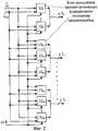
На фиг.1 приведена структурная схема устройства разрешения радиоимпульсных сигналов на фоне произвольной помехи; на фиг.2 - структурная схема блока корреляционной обработки сигнала, входящего в состав каждого канала обработки сигналов; на фиг.3 - структурная схема блока вычисления итогового функционала отношения правдоподобия; на фиг.4 - структурная схема радиочастотного блока; на фиг.5 - структурная схема блока формирования корреляционных интегралов; на фиг.6 - временная диаграмма, поясняющая принцип работы радиочастотного блока 3.Figure 1 shows the structural diagram of a device for resolving radio-pulse signals against arbitrary interference; figure 2 is a structural diagram of a block of correlation signal processing, which is part of each channel signal processing; figure 3 is a structural diagram of a unit for calculating the final functionality of the likelihood ratio; figure 4 is a structural diagram of a radio frequency block; figure 5 is a structural diagram of a block for the formation of correlation integrals; figure 6 is a timing diagram explaining the principle of operation of the radio frequency unit 3.
Устройство разрешения радиоимпульсных сигналов на фоне произвольной помехи содержит каналы 11-1H обработки сигналов, тактовый генератор 2, выходы которого соединены с тактовым входом радиочастотного блока 3, с тактовым входом блока 4 формирования копий сигналов и помех и с тактовыми входами каналов обработки сигналов 11-1H, выходы каждого из которых соединены с входами блока 5 сравнения, выходы которого являются выходами устройства, причем информационный вход устройства является входом радиочастотного блока 3, выход которого соединен с информационными входами каналов обработки сигналов 11-1H, а каждый канал обработки сигналов 11-1H содержит блок 6 корреляционной обработки и первые блоки 71-7L суммирования, причем выходы блока 6 корреляционной обработки соединены с входами соответствующих первых блоков 71-7L суммирования, а число каналов обработки сигналов 11-1H равно заданному числу комбинаций наложения разрешаемых радиоимпульсных сигналов, каждый канал обработки сигналов 11-1H дополнительно содержит блок 8 формирования корреляционных интегралов, выход которого соединен с входом блока 6 корреляционной обработки, причем первый вход блока 8 формирования корреляционных интегралов является входом канала обработки сигналов 11-1H и соединен с выходом радиочастотного блока 3, а второй вход блока 8 формирования корреляционных интегралов соединен с выходом блока 4 формирования копий сигналов и помех, вход которого является входом устройства, на который поступает информация о виде используемой расширяющей псевдослучайной последовательности (ПСП), кроме того, каждый канал обработки сигналов 11-1H содержит блок 10 вычисления итогового функционала отношения правдоподобия (БВФОП) текущей комбинации наложения разрешаемых радиоимпульсных сигналов, выход которого является выходом канала обработки сигналов 11-1H, причем соответствующие сигнальные входы БВФОП 10 подключены к соответствующим сигнальным выходам первых блоков 71-7L суммирования, которые параллельно подключены к соответствующим входам блока 9 вычисления апостериорных вероятностей, выходы которого соответственно подключены к входам блока 11 экстраполяции, сигнальные выходы которого соединены с соответствующими входами БВФОП 10 и соответствующими входами блока 9 вычисления апостериорных вероятностей. Система, обеспечивающая питание блоков, на чертеже не показана.A device for resolving radio pulse signals against arbitrary interference contains channels 11 -1H of signal processing, a clock generator 2, the outputs of which are connected to the clock input of the RF unit 3, to the clock input of the copy and signal copying unit 4 and to the clock inputs of the signal processing channels 11 -1H , the outputs of each of which are connected to the inputs of the comparison unit 5, the outputs of which are the outputs of the device, the information input of the device being the input of the RF unit 3, the output of which is connected to and information inputs of the signal processing channels 11 -1H , and each signal processing channel 11 -1H contains a
Блок 6 корреляционной обработки сигнала, входящий в состав каждого канала обработки сигналов 11-1H, изображенный на фиг.2, содержит блоки 121-12N вычисления частных релеевских функционалов отношения правдоподобия для каждой компоненты помехи и белого гауссовского шума и блоки 1301-13NL вычисления частных релеевских функционалов отношения правдоподобия для всех комбинаций наложения компонент разрешаемых радиоимпульсных сигналов, присутствующих в смеси и компонент помехи, а также белого гауссовского шума, информационные входы которых соединены с информационным выходом блока 8 формирования корреляционных интегралов, а информационные выходы блоков 121-12N и 1301-13NL соединены с информационными входами соответствующих первых блоков суммирования 70-7L.
Блок 10 вычисления итогового функционала отношения правдоподобия текущей комбинации наложения разрешаемых сигналов, входящий в состав каждого канала обработки сигналов, изображенный на фиг.3, содержит первые блоки 141-14L умножения, первые информационные входы которых соединены с соответствующими выходами первых блоков 71-7L суммирования, а вторые информационные входы первых блоков 141-14L умножения соединены с соответствующими выходами блока 11 экстраполяции, причем соответствующие выходы первых блоков 141-14L умножения соединены с соответствующими входами второго блока 15 суммирования, выход которого соединен со вторым входом блока 16 деления, первый вход которого соединен с выходом первого блока 70 суммирования, при этом выход блока деления 16 соединен с первым входом второго блока 17 умножения, выход которого является выходом канала обработки сигналов и входом блока 18 задержки, выход которого соединен с вторым входом второго блока 17 умножения.Block 10 calculating the final functional of the likelihood ratio of the current combination of overlapping allowed signals, which is part of each signal processing channel shown in Fig. 3, contains the first multiplication blocks 141 -14L , the first information inputs of which are connected to the corresponding outputs of the first blocks 71 - 7L summation and the second data inputs of the first blocks on January14 -14L multiplication are connected to respective outputs of the extrapolation unit 11, the respective outputs of the first blocks on January14 -14L respectively connected to the multiplication favoring inputs of the
Радиочастотный блок 3, изображенный на фиг.4, содержит третий блок 19 умножения и четвертый блок 20 умножения, первый информационный вход третьего блока 19 умножения и первый информационный вход четвертого блока 20 умножения соединены и являются входом устройства, на второй вход третьего блока 19 умножения поступает вектор отсчетов от генератора косинусного колебания, генератор косинусного колебания на схеме не показан, на второй вход четвертого блока 20 умножения поступает вектор отсчетов от генератора синусных колебаний, генератор синусных колебаний на схеме не показан, управляющие входы третьего блока 19 умножения и четвертого блока 20 умножения соединены с соответствующими выходами блока 21 управления, выход третьего блока 19 умножения соединен с входом третьего блока 22 суммирования, выход которого соединен с входом первого электронного ключа 24, причем выход третьего блока 22 суммирования дополнительно соединен с вторым входом этого же третьего блока 22 суммирования, а управляющий вход третьего блока 22 суммирования соединен с соответствующим выходом блока 21 управления, выход четвертого блока 20 умножения соединен с входом четвертого блока 23 суммирования, выход которого соединен с входом второго электронного ключа 25, причем выход четвертого блока 23 суммирования дополнительно соединен с вторым входом этого же четвертого блока 23 суммирования, а управляющий вход четвертого блока 23 суммирования соединен с соответствующим выходом блока 21 управления, управляющие входы первого и второго электронных ключей 24 и 25 соединены с соответствующими выходами блока 21 управления, а выходы первого и второго электронных ключей 24 и 25 являются выходами радиочастотного блока 3 и соединены с входами соответствующих каналов обработки сигналов 11-1H.The RF block 3 shown in FIG. 4 contains a
Блок 8 формирования корреляционных интегралов, изображенный на фиг.5, содержит блоки 261-2610 вычисления корреляционных интегралов для частных функционалов отношений правдоподобия, выходы которых соединены с входом аналого-цифрового преобразователя 27, выход которого является выходом блока 8 формирования корреляционных интегралов и соединен с входом блока 6 корреляционной обработки.Block 8 of the formation of correlation integrals, shown in figure 5, contains blocks 261 -2610 calculating the correlation integrals for private functionals of likelihood relations, the outputs of which are connected to the input of the analog-to-
Первые блоки 141-14L умножения, второй блок 15 суммирования, блок 16 деления, второй блок 17 умножения и блок 18 задержки, входящие в состав блока 10 вычисления итогового функционала отношения правдоподобия, третий и четвертый блоки 19, 20 умножения, третий и четвертый блоки 22, 23 суммирования и первый и второй электронные ключи 24, 25 и генераторы косинусных и синусных колебаний, входящие в радиочастотный блок 3, а также блоки 261-2610 вычисления корреляционных интегралов для частных функционалов отношений правдоподобия и аналого-цифровой преобразователь 27, входящие в блок 8 формирования корреляционных интегралов, могут быть выполнены по стандартным, опубликованным в литературе схемам.The first blocks 141 -14L of the multiplication, the
Устройство разрешения радиоимпульсных сигналов на фоне произвольной помехи работает следующим образом.A device for resolving radio pulse signals against a background of arbitrary interference works as follows.
Входной сигнал, представляющий собой сумму r радиоимпульсных сигналов разных типов

где I - число типов элементарных сигналов, J - число сигналов в ансамбле (число типов разрешаемых многоэлементных радиоимпульсных сигналов). Длительности элементарных радиосигналов равны Δtk=tk+1-tk и одинаковы, т.е. Δt1=Δt2=...=ΔtK=Δt.where I is the number of types of elementary signals, J is the number of signals in the ensemble (the number of types of resolved multi-element radio pulse signals). The durations of elementary radio signals are Δtk = tk + 1 -tk and are the same, i.e. Δt1 = Δt2 = ... = ΔtK = Δt.
В выражении (1)


Плотность вероятности случайного амплитудного множителя

где


Значения U(ti) являются координатными составляющими К-мерного вектора
Предполагается, что в канале связи сигнал (1) искажается шумовыми и хаотическими импульсными помехами (ХИП). Шумовые помехи состоят из внутренних и внешних шумов, которые в силу общепринятых допущений считаются гауссовскими, имеющими постоянную спектральную плотность мощности N0. ХИП представляет собой ординарный поток независимых импульсных помех с вероятностью Рп накладывающихся на k-ю временную позицию МЭС, которые представляются в виде радиоимпульсов известной формы:It is assumed that in the communication channel the signal (1) is distorted by noise and chaotic impulse noise (HIP). Noise interference consists of internal and external noise, which, by virtue of generally accepted assumptions, is considered Gaussian, having a constant power spectral density N0 . HIP is an ordinary flux of independent pulsed interference with probability Rp superimposed on the k-th temporary position of the MES, which are presented in the form of radio pulses of a known shape:

длительностью ТП. В выражении (4) UП(t) - комплексная амплитуда, uП⊥(t) и uП⊥(t) - квадратурные компоненты, φП - начальная фаза радиоимпульса импульсной помехи равномерно распределена в интервале [0,2π], bП - случайный амплитудный множитель, который описывается полирелеевым законом распределения:duration TP. In expression (4), UП (t) is the complex amplitude, uП⊥ (t) and uП⊥ (t) are the quadrature components, φП is the initial phase of the pulsed interference radio pulse is uniformly distributed in the interval [0,2π], bP is a random amplitude factor, which is described by the poly-Rayleigh distribution law:

Разрешаемые радиоимпульсные сигналы


В работе [Чабдаров Ш.М., Закиров З.Г., Надеев А.Ф., Файзуллин P.P., Егоров А.Е., Дараган М.А. Обобщенный алгоритм разрешения флуктуирующих многоэлементных сигналов/ Науч. практ. сб. Электронное приборостроение. Выпуск №5 (33). Казань, КГТУ/КАИ. 2003 г.] синтезирован оптимальный алгоритм разрешения марково-смешанных полигауссовых сигналов на фоне комплекса помех на основе байесовского критерия при одинаковых платах за ошибки:In the work [Chabdarov Sh.M., Zakirov Z.G., Nadeev A.F., Fayzullin P.P., Egorov A.E., Daragan M.A. A generalized algorithm for resolving fluctuating multi-element signals / Scientific. prakt. Sat Electronic instrumentation. Issue No. 5 (33). Kazan, KSTU / KAI. 2003] the optimal algorithm for resolving Markov-mixed poly-Gaussian signals against the background of a complex of interference based on the Bayesian criterion with the same fees for errors was synthesized:


В нашем случае распределения амплитудных множителей сигналов и помех представляются марково-смешанной полирелеевой моделью. Следует отметить, что распределение Релея является частным случаем распределения Райса, а возможность полирайсового представления распределения амплитуд полигауссовых дискретных сигналов и помех показана в работе [Чабдаров Ш.М. Полигауссовы приемники произвольно флуктуирующих сигналов. - Изв. вузов. Радиоэлектроника, 1977, Т.20, №9, с.32-38], таким образом, алгоритм (6) применим в нашем случае, когда случайные амплитудные множители сигналов и помех представлены марково-смешанной полирелеевой моделью.In our case, the distributions of the amplitude factors of the signals and interference are represented by a Markov-mixed poly-Rayleigh model. It should be noted that the Rayleigh distribution is a special case of the Rice distribution, and the possibility of a multi-rai representation of the distribution of amplitudes of poly-Gaussian discrete signals and interference is shown in [Chabdarov Sh.M. Polygaussian receivers of arbitrarily fluctuating signals. - Izv. universities. Radioelectronics, 1977, Vol. 20, No. 9, pp. 32-38], so algorithm (6) is applicable in our case, when random amplitude factors of signals and noise are represented by a Markov-mixed polar relay model.
В выражении (6) h - обозначает номер гипотезы о соответствующей комбинации сигналов, гипотеза h=1 соответствует комбинации полного отсутствия сигналов, итоговые функционалы отношения правдоподобия


где


Частные функционалы отношения правдоподобия для нашего случая, когда многоэлементный радиоимпульсный сигнал описывается выражением (1), а ХИП - выражением (4) вычисляются по методике, предложенной в работе [Ширман Я.Д. Разрешение и сжатие сигналов. М.: Сов. радио, 1974, 360 с.], и имеют вид:Particular likelihood ratio functionals for our case, when a multi-element radio pulse signal is described by expression (1), and HIP - expression (4) are calculated according to the technique proposed in [Shirman Y.D. Resolution and compression of signals. M .: Sov. radio, 1974, 360 pp.], and have the form:


где


Частные функционалы отношения правдоподобия (12), (13), (14) включают в себя дискретные корреляционные интегралы вида:Particular likelihood ratio functionals (12), (13), (14) include discrete correlation integrals of the form:


В случае обработки широкополосных радиоимпульсных сигналов в течение n циклов в устройстве производится обработка вектора соответствующего длительности одного информационного символа широкополосного радиоимпульсного сигнала, состоящего из определенной последовательности элементарных узкополосных радиоимпульсов (чипов).In the case of processing broadband radio pulse signals for n cycles, the device processes the vector of the corresponding duration of one information symbol of the broadband radio pulse signal, consisting of a certain sequence of elementary narrow-band radio pulses (chips).
Размерность входного вектора отсчетов, соответствующего одному информационному символу определяется частотой дискретизации. В результате дискретизации входного колебания получается вектор отсчетов, в котором каждому элементарному узкополосному радиоимпульсу (чипу) соответствует определенное число отсчетов.The dimension of the input sample vector corresponding to one information symbol is determined by the sampling frequency. As a result of sampling the input oscillation, a sample vector is obtained in which each elementary narrow-band radio pulse (chip) corresponds to a certain number of samples.
Каждый отсчет входного сигнала

Входной вектор отсчетов поступает на информационный вход радиочастотного блока 3, состоящего из двух каналов косинусного и синусного. Косинусный канал радиочастотного блока 3 содержит третий блок 19 умножения, третий блок 22 суммирования и первый электронный ключ 24. На первый вход третьего блока 19 умножения поступают отсчеты входного вектора
В результате обработки в радиочастотном блоке 3 входного вектора отсчетов


Блок 8 формирования корреляционных интегралов содержит блоки 261-2610 вычисления корреляционных интегралов для частных функционалов отношения правдоподобия, вычисления в этих блоках производятся в соответствии с выражениями (17)-(26). Выходы блоков 261-2610 вычисления корреляционных интегралов подключены к аналого-цифровому преобразователю 27 и значения корреляционных интегралов, вычисленные в соответствии с выражениями (17)-(26), поступают на вход блока 6 корреляционной обработки в виде v-разрядного двоичного кода.Block 8 for the formation of correlation integrals contains blocks 261 -2610 for calculating the correlation integrals for particular likelihood ratio functionals, the calculations in these blocks are performed in accordance with expressions (17) - (26). The outputs of the blocks 261 -2610 for calculating the correlation integrals are connected to the analog-to-
Блок 6 корреляционной обработки сигнала каждого канала состоит из блоков 121-12N, 1301-13NL вычисления частных релеевских функционалов отношения правдоподобия, которые после приема значений корреляционных интегралов, вычисленных в блоке 8 формирования корреляционных интегралов, формируют на своих выходах сигналы, пропорциональные частным релеевским функционалам отношения правдоподобия, входящих в выражения (10)-(11). Эти значения с соответствующих выходов каждого блока 6 корреляционной обработки сигнала поступают одновременно на информационные входы первых блоков 70-7L суммирования, где формируются сигналы, пропорциональные линейной комбинации частных релеевских функционалов отношения правдоподобия по всем помеховым компонентам. При этом на выходе первого блока 71 суммирования действует сигнал вида


Сигналы с выхода первых блоков 70-7L суммирования поступают одновременно на информационные входы блока 10 вычисления итогового функционала отношения правдоподобия и блока 9 вычисления апостериорных вероятностей. На выходе блока 9 вычисления апостериорных вероятностей формируются сигналы, пропорциональные апостериорным вероятностям комбинаций компонент разрешаемых радиоимпульсных сигналов, определяемых выражением (21), которые затем поступают на соответствующие входы блока 11 экстраполяции, где происходит вычисление оценок весов комбинаций релеевских компонент разрешаемых сигналов, в соответствии с выражением (8), которые, в свою очередь, подаются на соответствующие входы БВФОП 10. БВФОП 10 формирует итоговые функционалы отношения правдоподобия следующим образом. Сигналы, поступившие с выходов первых блоков 71-7L суммирования перемножаются с соответствующими сигналами, поступившими с выходов блока 11 экстраполяции в первых блоках 141-14L умножения, затем поступают на входы второго блока 15 суммирования, где вычисляется сумма, входящая в выражение (7), после чего в блоке 16 деления осуществляется деление значения, поступившего с выхода второго блока 15 суммирования, и значения, поступившего с выхода блока 70 суммирования. Полученное значение поступает на вход второго блока 17 умножения, выход которого связан с блоком 18 задержки, выход которого, в свою очередь, связан со вторым входом второго блока 17 умножения, где происходит вычисление итогового функционала отношения правдоподобия в строгом соответствии с выражением (7). Полученный сигнал с выхода БВФОП 10 каждого канала обработки сигналов 11-1H поступает на входы блока 5 сравнения, где путем выбора максимального значения в соответствии с выражением (6) и принятия решения в пользу определенной гипотезы о комбинации наложения разрешаемых сигналов, в результате, после n циклов работы устройства на выходах S1, S2,...,SH имеется информация о поступлении на вход устройства определенной комбинации сигналов. Таким образом, по сравнению с прототипом, который определяет наличие на входе соответствующего сигнала из различаемых, предлагаемое изобретение позволяет определять, сколько и какие из возможных радиоимпульсных сигналов присутствуют на входе.The signals from the output of the first blocks 70 -7L summation are simultaneously sent to the information inputs of the block 10 for calculating the final functional of the likelihood ratio and
Claims (1)
Translated fromRussianPriority Applications (1)
| Application Number | Priority Date | Filing Date | Title |
|---|---|---|---|
| RU2004120665/09ARU2269205C1 (en) | 2004-07-06 | 2004-07-06 | Device for resolving radio-pulse signals in random noise background |
Applications Claiming Priority (1)
| Application Number | Priority Date | Filing Date | Title |
|---|---|---|---|
| RU2004120665/09ARU2269205C1 (en) | 2004-07-06 | 2004-07-06 | Device for resolving radio-pulse signals in random noise background |
Publications (1)
| Publication Number | Publication Date |
|---|---|
| RU2269205C1true RU2269205C1 (en) | 2006-01-27 |
Family
ID=36047977
Family Applications (1)
| Application Number | Title | Priority Date | Filing Date |
|---|---|---|---|
| RU2004120665/09ARU2269205C1 (en) | 2004-07-06 | 2004-07-06 | Device for resolving radio-pulse signals in random noise background |
Country Status (1)
| Country | Link |
|---|---|
| RU (1) | RU2269205C1 (en) |
Cited By (3)
| Publication number | Priority date | Publication date | Assignee | Title |
|---|---|---|---|---|
| RU2416807C2 (en)* | 2009-01-23 | 2011-04-20 | Общество с ограниченной ответственностью "Конструкторское бюро радиосистем" | Method for radar measurement of velocity and coordinates of objects and system for implementing said method |
| RU2416876C2 (en)* | 2008-02-04 | 2011-04-20 | Владимир Алексеевич Гарбузов | Method of processing additive signal mixture and white noise |
| RU2615791C1 (en)* | 2015-10-27 | 2017-04-11 | Федеральное государственное бюджетное образовательное учреждение высшего профессионального образования "Казанский национальный исследовательский технический университет им. А.Н. Туполева - КАИ" (КНИТУ-КАИ) | Method for separating signals under action of intra-system interference and device for its implementation |
Citations (5)
| Publication number | Priority date | Publication date | Assignee | Title |
|---|---|---|---|---|
| US4630305A (en)* | 1985-07-01 | 1986-12-16 | Motorola, Inc. | Automatic gain selector for a noise suppression system |
| US4811404A (en)* | 1987-10-01 | 1989-03-07 | Motorola, Inc. | Noise suppression system |
| SU1596469A1 (en)* | 1988-12-14 | 1990-09-30 | Казанский Авиационный Институт Им.А.Н.Туполева | Device for detecting signals against random interference background |
| SU1660188A1 (en)* | 1988-09-08 | 1991-06-30 | Предприятие П/Я Р-6510 | Adaptive device for noise suppression in voice signals |
| RU2169992C2 (en)* | 1995-11-13 | 2001-06-27 | Моторола, Инк | Method and device for noise suppression in communication system |
- 2004
- 2004-07-06RURU2004120665/09Apatent/RU2269205C1/ennot_activeIP Right Cessation
Patent Citations (5)
| Publication number | Priority date | Publication date | Assignee | Title |
|---|---|---|---|---|
| US4630305A (en)* | 1985-07-01 | 1986-12-16 | Motorola, Inc. | Automatic gain selector for a noise suppression system |
| US4811404A (en)* | 1987-10-01 | 1989-03-07 | Motorola, Inc. | Noise suppression system |
| SU1660188A1 (en)* | 1988-09-08 | 1991-06-30 | Предприятие П/Я Р-6510 | Adaptive device for noise suppression in voice signals |
| SU1596469A1 (en)* | 1988-12-14 | 1990-09-30 | Казанский Авиационный Институт Им.А.Н.Туполева | Device for detecting signals against random interference background |
| RU2169992C2 (en)* | 1995-11-13 | 2001-06-27 | Моторола, Инк | Method and device for noise suppression in communication system |
Cited By (3)
| Publication number | Priority date | Publication date | Assignee | Title |
|---|---|---|---|---|
| RU2416876C2 (en)* | 2008-02-04 | 2011-04-20 | Владимир Алексеевич Гарбузов | Method of processing additive signal mixture and white noise |
| RU2416807C2 (en)* | 2009-01-23 | 2011-04-20 | Общество с ограниченной ответственностью "Конструкторское бюро радиосистем" | Method for radar measurement of velocity and coordinates of objects and system for implementing said method |
| RU2615791C1 (en)* | 2015-10-27 | 2017-04-11 | Федеральное государственное бюджетное образовательное учреждение высшего профессионального образования "Казанский национальный исследовательский технический университет им. А.Н. Туполева - КАИ" (КНИТУ-КАИ) | Method for separating signals under action of intra-system interference and device for its implementation |
Similar Documents
| Publication | Publication Date | Title |
|---|---|---|
| Li et al. | Maximum likelihood angle estimation for signals with known waveforms | |
| US3925650A (en) | Method and apparatus for detecting a repetitive signal in a noisy background | |
| CN104168233A (en) | DSSS/UQPSK signal pseudo code sequence estimation method based on characteristic decomposition and Messay algorithm | |
| Kak | Classification of random binary sequences using Walsh-Fourier analysis | |
| RU2269205C1 (en) | Device for resolving radio-pulse signals in random noise background | |
| Legg et al. | Performance bounds for polynomial phase parameter estimation with nonuniform and random sampling schemes | |
| RU2110150C1 (en) | Signal detector | |
| RU2153230C1 (en) | Method and device for synchronization of complex m sequence | |
| RU2107394C1 (en) | Multiple-channel adaptive receiver | |
| RU42373U1 (en) | DEVICE FOR PERMISSION OF RADIO PULSE SIGNALS ON THE BACKGROUND OF ARBITRARY INTERFERENCE | |
| US7299161B2 (en) | Decorrelation of signals | |
| Yaushev et al. | Quasi-determined algorithm for resolution of randomly fluctuating signals and chaotic pulse interference | |
| RU2012108704A (en) | METHOD FOR ACCELERATED SEARCH FOR WIDEBAND SIGNALS AND DEVICE FOR ITS IMPLEMENTATION | |
| López-Asunción et al. | Design and Implementation of a Real-Time Low-Latency Automatic Modulation Classifier | |
| RU2718753C1 (en) | Device of the third decision circuit of accelerated search and efficient reception of broadband signals | |
| Barreto et al. | FPGA design and implementation of a real-time FM/PM pseudo random waveform generation for noise radars | |
| Gorgadze et al. | Accelerated evaluation of spread spectrum signals synchronization parameters | |
| Su et al. | Deep learning enabled parameters estimation using time-frequency analysis of chirp signals | |
| RU2127954C1 (en) | Method and device for synchronization of m sequence | |
| Hu | Hierarchical subtraction with neural density estimators as a general solution to overlapping gravitational wave signals | |
| Samarah | A 320 mhz digital linear frequency modulated signal generator for radar applications using fpga technology | |
| RU2251811C2 (en) | Device for signal resolution on random noise background | |
| RU2808721C1 (en) | Device of the third decisive circuit for accelerated search and efficient reception of broadband signals | |
| Meng et al. | Detection of DS &FH hybrid Spread Spectrum Signal in TT & C communication | |
| Lee et al. | Synthesizing number generators for stochastic computing using mixed integer programming |
Legal Events
| Date | Code | Title | Description |
|---|---|---|---|
| MM4A | The patent is invalid due to non-payment of fees | Effective date:20070707 |