RU2264052C1 - Microwave heater for fluid or free-flowing substances - Google Patents
Microwave heater for fluid or free-flowing substancesDownload PDFInfo
- Publication number
- RU2264052C1 RU2264052C1RU2004106381/09ARU2004106381ARU2264052C1RU 2264052 C1RU2264052 C1RU 2264052C1RU 2004106381/09 ARU2004106381/09 ARU 2004106381/09ARU 2004106381 ARU2004106381 ARU 2004106381ARU 2264052 C1RU2264052 C1RU 2264052C1
- Authority
- RU
- Russia
- Prior art keywords
- conductor
- line
- along
- length
- microwave
- Prior art date
Links
- 239000012530fluidSubstances0.000titleclaimsdescription4
- 239000000126substanceSubstances0.000titleabstract4
- 239000004020conductorSubstances0.000claimsabstractdescription56
- 238000010438heat treatmentMethods0.000abstractdescription4
- 238000005516engineering processMethods0.000abstractdescription3
- 230000000694effectsEffects0.000abstractdescription2
- 230000010363phase shiftEffects0.000abstract1
- 239000002184metalSubstances0.000description12
- 239000007788liquidSubstances0.000description11
- 230000005855radiationEffects0.000description11
- 238000009826distributionMethods0.000description8
- 238000004804windingMethods0.000description6
- 230000001788irregularEffects0.000description3
- 230000005540biological transmissionEffects0.000description2
- 238000004891communicationMethods0.000description2
- 230000005672electromagnetic fieldEffects0.000description2
- 239000000463materialSubstances0.000description2
- 150000003839saltsChemical class0.000description2
- XLYOFNOQVPJJNP-UHFFFAOYSA-NwaterSubstancesOXLYOFNOQVPJJNP-UHFFFAOYSA-N0.000description2
- 238000003491arrayMethods0.000description1
- 238000010009beatingMethods0.000description1
- 230000015572biosynthetic processEffects0.000description1
- 230000003247decreasing effectEffects0.000description1
- 230000001419dependent effectEffects0.000description1
- 239000003814drugSubstances0.000description1
- 230000005520electrodynamicsEffects0.000description1
- 239000011152fibreglassSubstances0.000description1
- 239000013505freshwaterSubstances0.000description1
- 238000009434installationMethods0.000description1
- 230000003993interactionEffects0.000description1
- 238000000034methodMethods0.000description1
- 239000010705motor oilSubstances0.000description1
- 239000003921oilSubstances0.000description1
- 230000000149penetrating effectEffects0.000description1
- 230000000135prohibitive effectEffects0.000description1
- 238000007670refiningMethods0.000description1
- 230000001131transforming effectEffects0.000description1
- 238000009827uniform distributionMethods0.000description1
Images

Landscapes
- Constitution Of High-Frequency Heating (AREA)
Abstract
Description
Translated fromRussianИзобретение относится к области технологии микроволновой обработки жидких и сыпучих сред и может быть использовано в различных отраслях народного хозяйства и техники: в сельском хозяйстве, медицине, в пищевой и нефтеперерабатывающей промышленности для создания аппаратов сверхвысокочастотной (СВЧ) обработки жидких или сыпучих сред.The invention relates to the field of microwave processing technology for liquid and granular media and can be used in various sectors of the national economy and technology: in agriculture, medicine, in the food and oil refining industries to create microwave devices for processing liquid or granular media.
Известны устройства микроволновых нагревателей для СВЧ-обработки жидких и сыпучих сред, см. например, патент РФ 2074530 от 27.02.1997 г. МПК, Н 05 В 6/64 - Микроволновый нагреватель жидких сред. Формирование распределения в устройстве такого типа обеспечивается спиральным проводником, намотанным на диэлектрической трубе, по которой протекает обрабатываемая жидкость. В таких устройствах решается задача согласования генератора СВЧ, что обеспечивает эффективный нагрев жидкости, но при этом не решается задача формирования распределения энергии, отдаваемой жидкости вдоль нагревательного элемента.Known devices for microwave heaters for microwave processing of liquid and granular media, see, for example, RF patent 2074530 from 02.27.1997 IPC, H 05 V 6/64 - Microwave fluid heater. The formation of the distribution in this type of device is ensured by a spiral conductor wound on a dielectric pipe through which the processed fluid flows. In such devices, the problem of matching the microwave generator is solved, which ensures efficient heating of the liquid, but the problem of forming the distribution of energy given off by the liquid along the heating element is not solved.
Прототипом изобретения является Патент США 4221948 от 09.09.1980, МПК Н 05 В 9/06 - Apparatus for subjecting a material to electromagnetic waves.The prototype of the invention is US Patent 4,221,948 dated 09/09/1980, IPC H 05 B 9/06 - Apparatus for subjecting a material to electromagnetic waves.
Микроволновая обработка в устройствах, представленных в данном патенте, производится микроволновым нагревателем, состоящим либо из отдельного излучателя - линейной антенны (штырь, спираль), либо из системы дискретных излучателей электромагнитной энергии (волноводно-щелевые решетки), погруженных в среду с потерями. Недостатком этих устройств является то, что они не обеспечивают требуемую равномерность распределения электромагнитной энергии в обрабатываемой среде с потерями в результате того, что система дискретных излучателей в среде с потерями формирует локальное воздействие электромагнитного поля на обрабатываемую среду в непосредственной близости от излучателя. А линейные антенны типа штыря, спирали формируют в среде с потерями спадающее распределение тока в антенне, что приводит к неравномерности обработки. Входное сопротивление таких нагревателей в сильной степени зависит от электромагнитных параметров обрабатываемой среды (см., например Р.Кинг, Г.Смит. Антенны в материальных средах. М.: Мир, 1984 г., т.2, стр.447-449), поэтому при изменении в широких пределах параметров этой среды трудно обеспечить режим согласования источника электромагнитной энергии с микроволновым нагревателем. Производительность установок, работающих с такими нагревателями, ограничена, в частности, максимально допустимой плотностью электромагнитной энергии, формируемой в обрабатываемой среде вблизи поверхности отдельных излучателей. Это ограничивает мощность СВЧ-сигнала, подводимого к микроволновому нагревателю.Microwave processing in the devices presented in this patent is performed by a microwave heater, consisting of either a separate emitter - a linear antenna (pin, spiral), or from a system of discrete emitters of electromagnetic energy (waveguide-slot arrays) immersed in the medium with losses. The disadvantage of these devices is that they do not provide the required uniform distribution of electromagnetic energy in the medium with losses due to the fact that the system of discrete emitters in the medium with losses forms a local effect of the electromagnetic field on the medium being processed in the immediate vicinity of the radiator. And linear antennas of the pin and spiral type form a decreasing current distribution in the antenna with loss in the medium, which leads to uneven processing. The input impedance of such heaters is highly dependent on the electromagnetic parameters of the medium being treated (see, for example, R. King, G. Smith. Antennas in material media. M: Mir, 1984, vol. 2, p. 447-449) therefore, when changing over a wide range of parameters of this medium, it is difficult to provide a mode of matching the source of electromagnetic energy with a microwave heater. The performance of installations operating with such heaters is limited, in particular, by the maximum allowable density of electromagnetic energy generated in the medium being processed near the surface of individual emitters. This limits the power of the microwave signal supplied to the microwave heater.
Решаемая техническая задача предлагаемого изобретения заключается в повышении равномерности распределения электромагнитной энергии СВЧ в обрабатываемой среде с потерями вдоль микроволнового нагревателя, обеспечении режима согласования источника электромагнитной энергии с микроволновым нагревателем при изменении в широких пределах электромагнитных параметров обрабатываемой среды, а также обеспечении возможности увеличения допустимой мощности СВЧ-сигнала, подводимого к микроволновому нагревателю.The technical problem of the invention is to increase the uniformity of the distribution of microwave electromagnetic energy in the medium with losses along the microwave heater, provide a mode of matching the electromagnetic energy source with the microwave heater when the electromagnetic parameters of the medium are varied over a wide range, and also provide the possibility of increasing the permissible microwave power signal supplied to the microwave heater.
Решаемая техническая задача в микроволновом нагревателе жидкой или сыпучей среды в первом его варианте, состоящем из излучателя электромагнитной энергии, размещенного в радиопрозрачной трубе, расположенной в резервуаре для обрабатываемой среды, достигается тем, что излучатель электромагнитной энергии выполнен в виде открытой двухпроводной линии длиной L>λ/2, один проводник которой относительно другого проводника на длине двухпроводной линии L выполнен длиннее на величину ΔL>0 с удлинением вдоль всей длины линии, при этом удлинение проводника двухпроводной линии на протяжении ее длины L выполнено монотонным или дискретным, где λ - длина электромагнитной волны источника СВЧ-энергии; L - длина двухпроводной линии по оси радиопрозрачной трубы; ΔL - величина удлинения одного проводника двухпроводной линии относительно другого на длине линии L.The technical problem to be solved in a microwave heater of a liquid or granular medium in its first embodiment, consisting of an electromagnetic energy emitter placed in a radiolucent tube located in a medium tank, is achieved by the fact that the electromagnetic energy emitter is made in the form of an open two-wire line of length L> λ / 2, one conductor of which with respect to the other conductor along the length of the two-wire line L is made longer by an amount ΔL> 0 with an extension along the entire length of the line, while the extension of the wire arrestor two-wire line over its length L is satisfied monotone or discrete, where λ - length of the electromagnetic wave source of microwave energy; L is the length of the two-wire line along the axis of the radiotransparent pipe; ΔL is the elongation of one conductor of the two-wire line relative to the other along the length of the line L.
Решаемая техническая задача в микроволновом нагревателе жидкой или сыпучей среды в его втором варианте, состоящем из излучателя электромагнитной энергии, размещенного в радиопрозрачной трубе, расположенной в резервуаре для обрабатываемой среды, достигается тем, что излучатель электромагнитной энергии выполнен в виде полого металлического волновода длиной L, закороченного на конце, стенки которого выполнены в виде сетчатой структуры с ячейками, размеры которых вдоль волновода изменяются от 0<dяч≪λ до dяч≤λ/2 и с интервалами между ячейками, много меньшими длины волны dин≪λ, а сетчатая структура на стенках волновода может быть выполнена либо из перфорированного металлического листа с размерами отверстий dот=dяч, либо из металлической сетки с размерами ячеек dяч, где λ - длина электромагнитной волны источника СВЧ-энергии; L - длина металлического волновода вдоль оси радиопрозрачной трубы; dяч - максимальный размер ячейки сетчатой структуры в направлении касательного к металлическим стенкам магнитного поля в волноводе; dин - расстояние между ближайшими кромками соседних ячеек сетчатой структуры на стенках волновода.The technical problem to be solved in a microwave heater of a liquid or granular medium in its second embodiment, consisting of an electromagnetic energy emitter placed in a radiotransparent tube located in the medium to be treated, is achieved by the fact that the electromagnetic energy emitter is made in the form of a hollow metal waveguide of length L shorted on the end walls of which are made in the form of net-like structure with a mesh whose dimensions vary along the waveguide from 0 <d «λ tocell #cell # d ≤λ / 2 and intervals between yache Kami, much smaller than the wavelength of dyn «λ, a mesh structure on the waveguide walls may be made either from a perforated metal sheet with the dimensionsof the apertures d = dThe ball, or of a metal grid with mesh size dCell #, where λ - length of the electromagnetic wave microwave energy source; L is the length of the metal waveguide along the axis of the radiolucent tube; dcell - the maximum mesh size of the mesh in the direction of the magnetic field tangent to the metal walls in the waveguide; din - the distance between the nearest edges of adjacent cells of the mesh structure on the walls of the waveguide.
На фигуре 1 показано продольное сечение микроволнового нагревателя с монотонным удлинением проводника, выполненного в виде равноугольной спирали, его первый вариант.The figure 1 shows a longitudinal section of a microwave heater with a monotonic extension of the conductor, made in the form of an equiangular spiral, its first variant.
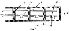
На фигуре 2 показана конфигурация двухпроводной линии для случая дискретного удлинения проводника для микроволнового нагревателя по его первому варианту.Figure 2 shows the configuration of a two-wire line for the case of discrete extension of the conductor for a microwave heater in its first embodiment.
На фигуре 3 показано продольное сечение микроволнового нагревателя, его второй вариант.Figure 3 shows a longitudinal section of a microwave heater, its second option.
Микроволновый нагреватель жидкой или сыпучей среды по фигурам 1, 2 состоит из излучателя электромагнитной энергии, выполненного в виде двухпроводной линии 1, размещенной в радиопрозрачной трубе 2, расположенной в резервуаре 3 для обрабатываемой среды 4. Двухпроводная линия 1 длиной L>λ/2 состоит из двух проводников: из первого проводника 5 и второго проводника 6 в случае монотонного удлинения одного из этих проводников или из третьего проводника 7 и четвертого проводника 8 в случае дискретного удлинения. Проводники линии 1 установлены в трубе 2 вдоль ее продольной оси Z на диэлектрических шайбах 9. Первый проводник 5 или третий проводник 7 двухпроводной линии 1 за счет своей конфигурации имеет большую длину, чем второй проводник 6 или четвертый проводник 8, т.е. выполнены с удлинением ΔL>0. Это удлинение может быть выполнено либо монотонным вдоль всей оси линии, пропорционально коэффициенту удлинения K(z), характеризующимся непрерывной функцией от (z). При этом монотонное удлинение проводников относительно друг друга, например, может быть выполнено, например, в виде спиральной намотки первого проводника 5 относительно второго проводника 6 либо дискретным - обеспеченным фазосдвигающими элементами 10, которые включенны, например, в третий проводник 7 с шагом dш. Вход двухпроводной линии 1 соединен с симметричным выходом источника СВЧ-энергии 11.The microwave heater for liquid or granular medium according to figures 1, 2 consists of an emitter of electromagnetic energy, made in the form of a two-wire line 1, placed in a
Микроволновый нагреватель жидкой или сыпучей среды по фигуре 3, его второй вариант, состоит из излучателя электромагнитной энергии, выполненного в виде металлического волновода 12, расположенного в радиопрозрачной трубе 2, размещенной в резервуаре 3 для обрабатываемой среды 4. Металлический волновод 12 закорочен на конце 13. Металлические стенки волновода 12 выполнены в виде сетчатой структуры с ячейками 14, размер которых dяч изменяется вдоль волновода от 0<dяч≪λ до dяч≤λ/2 и с интервалом dин, характеризующим расстояние между ближайшими кромками соседних ячеек сетчатой структуры, много меньшим длины волны dин≪λ. Сетчатая структура на стенках волновода 12 может быть выполнена либо из перфорированного металлического листа с размерами отверстий dот=dяч, либо из металлической сетки с размерами ячеек dяч.The microwave heater of a liquid or granular medium according to figure 3, its second variant, consists of an electromagnetic energy emitter made in the form of a
Работа микроволнового нагревателя, в его первом и втором вариантах, осуществляется следующим образом. Потери электромагнитной энергии СВЧ, подведенной на вход двухпроводной линии 1, в обрабатываемой среде 4 складываются из потерь части внешнего поля волны типа Т в линии 1, существующего снаружи радиопрозрачной трубы, и составляющих поля излучения этой линии. Внешнее поле волны типа Т и его потери определяются геометрией поперечного сечения линии 1 и размерами радиопрозрачной трубы 2. Потери, обеспеченные излучением линии 1 в обрабатываемой среде 4, зависят от величины разбаланса токов в ее проводниках по фазе и амплитуде, вызванного фазовой задержкой токов в первом проводнике 5 относительно второго проводника 6 и в третьем проводнике 7 относительно четвертого проводника 8. В данном изобретении разбаланс токов обеспечивается фазовой задержкой за счет удлинения одного проводника относительно другого. На участках линии 1, где фазовая задержка становится кратна нечетному числу π токи в первом проводнике 5 и втором проводнике 6, а также в третьем проводнике 7 и четвертом проводнике 8 становятся синфазными. Излучение линии 1 в этих участках становится эквивалентным излучению одиночному проводнику с суммарным током. На таких участках излучение линии 1 будет максимальным. Таким образом, изменяя фазовую задержку токов вдоль проводников 5, 6 или 7, 8 относительно друг друга вдоль линии 1, будет изменяться величина энергии потерь в обрабатываемой среде 4, обеспеченное излучением различных участков линии 1. Удлинение проводников относительно друг друга может быть непрерывным, например, выполненное в виде спиральной намотки первого проводника 5 относительно второго проводника 6. При этом путем плавного избиения шага намотки проводника 5 вдоль линии обеспечивается плавное изменение его удлинения и соответственно изменение интенсивности излучения различных участков линии 1. Этим обеспечивается изменение связи линии 1 с обрабатываемой средой 4 за счет изменения составляющей поля излучения вдоль нее. На фигуре 2 приведен пример дискретного удлинения третьего проводника 7 относительно четвертого проводника 8 в линии 1. В этом случае изменение параметров связи линии 1 с обрабатываемой средой 4 будет изменяться дискретно вдоль линии 1.The operation of the microwave heater, in its first and second versions, is as follows. The loss of microwave electromagnetic energy supplied to the input of the two-wire line 1 in the medium 4 is the sum of the losses of a part of the external field of the T wave in line 1 existing outside the radiolucent tube and the components of the radiation field of this line. The external field of a wave of type T and its losses are determined by the geometry of the cross-section of line 1 and the dimensions of the
В случае металлического волновода 12 со стенками из сетчатой структуры, выполненной либо из перфорированного листа с размерами отверстий dот=dяч, либо из металлической сетки с размерами ячеек dяч, величина энергии СВЧ-проникающей через ячейки 14 сетчатой структуры, зависит от размеров ячеек dяч вдоль силовых линий магнитного поля касательного к стенкам волновода 12. Эта зависимость может быть оценена, например, методом усредненных граничных условий, см., например, Конторович М.И., Астраханин М.И., Акимов В.П., Ферсман Г.А. Электродинамика сетчатых структур. М.: Радио и связь, 1987 г., стр.9-23.In the case of a
Ограничение размеров ячеек 14 сетчатой структуры 12 от 0<dяч≪λ до dяч≤λ/2 следует из необходимости обеспечения запредельных размеров отверстий в этих ячейках, когда излучение через них может рассматриваться как излучение из запредельного волновода. При этом интенсивность излучения из ячеек зависит от ее размера dяч и будет увеличиваться с увеличением этого размера. С превышением размера dяч=λ/2 интенсивность излучения будет определяться свойствами открытого конца волновода. См. например, Шапиро Д.Н. Основы теории электромагнитного экранирования. - М.: Энергия, 1975 г. стр.56-65.The limitation of the size of
Повышение равномерности распределения электромагнитной энергии СВЧ в обрабатываемой среде 4 с потерями вдоль микроволнового нагревателя в первом его варианте обеспечивается плавным распределением удлинения проводников 5, 6 и 7, 8 относительно друг друга вдоль двухпроводной линии 1 и величиной полного удлинения ΔL одного из проводников относительно другого проводника линии 1. Во втором его варианте повышение равномерности распределения электромагнитной энергии СВЧ в обрабатываемой среде 4 с потерями вдоль микроволнового нагревателя обеспечивается изменением вдоль волновода 12 размеров ячеек 14.The increase in the uniformity of the distribution of microwave electromagnetic energy in the medium 4 with losses along the microwave heater in its first embodiment is ensured by a smooth distribution of the elongation of the
Режим согласования источника электромагнитной энергии 11 с микроволновым нагревателем 1 и 12 при изменении в широких пределах электромагнитных параметров обрабатываемой среды 4 обеспечивается за счет широкополосных трансформирующих свойств линии 1 и волновода 12, которые являются нерегулярными линиями с плавно изменяющимися параметрами. См., например, Сазонов Д.Н., Гридин А.Н., Мишустин Б.А. Устройства СВЧ. М.: Высшая школа, 1981 г., стр.184-187. В данном случае широкополосные свойства микроволнового нагревателя определяются допустимым диапазоном изменения электромагнитных параметров обрабатываемой среды 4.The mode of coordination of the source of electromagnetic energy 11 with the
Ограничение минимальной длины двухпроводной линии L>λ/2 вызвано условием обеспечения широкополосных свойств плавных нерегулярных отрезков линий передачи, см., например, Сазонов Д.Н., Гридин А.Н., Мишустин Б.А. Устройства СВЧ. М.: Высшая школа, 1981 г., стр.184-187.The limitation of the minimum length of a two-wire line L> λ / 2 is caused by the condition for ensuring broadband properties of smooth irregular segments of transmission lines, see, for example, Sazonov D.N., Gridin A.N., Mishustin B.A. Microwave devices. M.: Higher School, 1981, pp. 184-187.
Ограничение dин≪λ диктуется необходимостью обеспечить для плавных нерегулярных линий передачи равномерность изменения их распределенных параметров вдоль линии 1.The restriction din ≪λ is dictated by the need to ensure for smooth irregular transmission lines a uniform change in their distributed parameters along line 1.
Возможность увеличения допустимой мощности сигнала СВЧ, подводимого к микроволновому нагревателю 1 и 12, по сравнению с прототипом обеспечивается тем, что поверхность взаимодействия по электромагнитному полю между микроволновым нагревателем и обрабатываемой средой в предложенном изобретении больше, чем у прототипа. Поэтому относительно прототипа плотность электромагнитной энергии, воздействующей на обрабатываемую среду 4, при прочих равных условиях в предложенном изобретении будет меньше. Это позволяет увеличить мощность, подводимую к излучателю.The possibility of increasing the allowable power of the microwave signal supplied to the
Микроволновый нагреватель для нагрева жидкостей в трубопроводе был реализован в радиопрозрачной трубе 2 диаметром 40 мм, выполненной из стеклотекстолита. В линии было осуществлено равномерное удлинение проводника в виде равноугольной спиральной намотки одного проводника относительно другого с радиусом намотки 0,1λ и углом намотки спирали θ=24° по отношению к оси Z. Такое выполнение проводника характеризуется коэффициентом удлинения K(z)=1/Cosθ=1,1. Длина линии L=5λ, полное удлинение спирального проводника на всей длине линии по отношению к прямому проводнику на частоте 2450 МГц составляло ΔL=0,5λ. Данный микроволновый нагреватель при погружении в различные жидкости обеспечил следующие параметры (см. таблицу).A microwave heater for heating liquids in the pipeline was implemented in a
Claims (1)
Translated fromRussianPriority Applications (1)
| Application Number | Priority Date | Filing Date | Title |
|---|---|---|---|
| RU2004106381/09ARU2264052C1 (en) | 2004-03-03 | 2004-03-03 | Microwave heater for fluid or free-flowing substances |
Applications Claiming Priority (1)
| Application Number | Priority Date | Filing Date | Title |
|---|---|---|---|
| RU2004106381/09ARU2264052C1 (en) | 2004-03-03 | 2004-03-03 | Microwave heater for fluid or free-flowing substances |
Publications (2)
| Publication Number | Publication Date |
|---|---|
| RU2004106381A RU2004106381A (en) | 2005-08-10 |
| RU2264052C1true RU2264052C1 (en) | 2005-11-10 |
Family
ID=35844913
Family Applications (1)
| Application Number | Title | Priority Date | Filing Date |
|---|---|---|---|
| RU2004106381/09ARU2264052C1 (en) | 2004-03-03 | 2004-03-03 | Microwave heater for fluid or free-flowing substances |
Country Status (1)
| Country | Link |
|---|---|
| RU (1) | RU2264052C1 (en) |
Cited By (2)
| Publication number | Priority date | Publication date | Assignee | Title |
|---|---|---|---|---|
| WO2011155810A1 (en)* | 2010-06-09 | 2011-12-15 | Shilikbayeva Arna Serikovna | Method for heating a circulating liquid in heating system pipes |
| RU2439863C1 (en)* | 2010-12-13 | 2012-01-10 | Федеральное государственное образовательное учреждение высшего профессионального образования "Мурманский государственный технический университет" (ФГОУВПО "МГТУ") | Device for heating-up of viscous dielectric products during their transportation through pipelines |
Citations (4)
| Publication number | Priority date | Publication date | Assignee | Title |
|---|---|---|---|---|
| US4221948A (en)* | 1976-11-17 | 1980-09-09 | Jean Olivier A L | Apparatus for subjecting a material to electromagnetic waves |
| DE3903558A1 (en)* | 1989-02-07 | 1990-08-23 | Rennebeck Klaus | Frost protection device for rapid safety of floating liquid or sedimentation in containers, tanks and boilers |
| RU2074530C1 (en)* | 1992-06-02 | 1997-02-27 | Товарищество с ограниченной ответственностью "Научно-техническое предприятие "Ликташ" | Microwave heater of liquid media |
| RU2125350C1 (en)* | 1995-01-26 | 1999-01-20 | Таганрогский научно-исследовательский институт связи | Microwave absorbing chamber |
- 2004
- 2004-03-03RURU2004106381/09Apatent/RU2264052C1/ennot_activeIP Right Cessation
Patent Citations (4)
| Publication number | Priority date | Publication date | Assignee | Title |
|---|---|---|---|---|
| US4221948A (en)* | 1976-11-17 | 1980-09-09 | Jean Olivier A L | Apparatus for subjecting a material to electromagnetic waves |
| DE3903558A1 (en)* | 1989-02-07 | 1990-08-23 | Rennebeck Klaus | Frost protection device for rapid safety of floating liquid or sedimentation in containers, tanks and boilers |
| RU2074530C1 (en)* | 1992-06-02 | 1997-02-27 | Товарищество с ограниченной ответственностью "Научно-техническое предприятие "Ликташ" | Microwave heater of liquid media |
| RU2125350C1 (en)* | 1995-01-26 | 1999-01-20 | Таганрогский научно-исследовательский институт связи | Microwave absorbing chamber |
Cited By (2)
| Publication number | Priority date | Publication date | Assignee | Title |
|---|---|---|---|---|
| WO2011155810A1 (en)* | 2010-06-09 | 2011-12-15 | Shilikbayeva Arna Serikovna | Method for heating a circulating liquid in heating system pipes |
| RU2439863C1 (en)* | 2010-12-13 | 2012-01-10 | Федеральное государственное образовательное учреждение высшего профессионального образования "Мурманский государственный технический университет" (ФГОУВПО "МГТУ") | Device for heating-up of viscous dielectric products during their transportation through pipelines |
Also Published As
| Publication number | Publication date |
|---|---|
| RU2004106381A (en) | 2005-08-10 |
Similar Documents
| Publication | Publication Date | Title |
|---|---|---|
| Paulides et al. | A patch antenna design for application in a phased-array head and neck hyperthermia applicator | |
| US10165630B2 (en) | Traveling wave antenna for electromagnetic heating | |
| CN105261841A (en) | Quasi-surface plasmon-based leaky-wave antenna | |
| Hashemi et al. | Evolution of composite right/left-handed leaky-wave antennas | |
| JP2002510886A (en) | Circuit and method for removing metal surface current | |
| CN112332081B (en) | Wide-lobe complementary source antenna based on microstrip structure | |
| SE518571C2 (en) | Antenna for portable radio devices and radio telephone | |
| CN103490153A (en) | Subminiature ultra-wide-band helical antenna | |
| Wang et al. | End-fire surface wave antenna with metasurface coating | |
| CN111293384B (en) | Radio frequency phase shifting device | |
| KR20140050633A (en) | Transmission line rf applicator for plasma chamber | |
| RU2264052C1 (en) | Microwave heater for fluid or free-flowing substances | |
| US10320045B2 (en) | Superposition of guided surface waves on lossy media | |
| TW200401590A (en) | Plasma treatment device | |
| US20110273350A1 (en) | Tapered slot antenna | |
| US20220022293A1 (en) | Microwave reactor for continuous treatment by microwaves of a flowing fluid medium | |
| RU2234824C1 (en) | Method and device for microwave treatment of liquid or loose media | |
| Lee | Investigation of pulse characteristics of a novel cylindrically slotted cloaked antenna | |
| Zainud-Deen et al. | Reconfigurable sea-water based reflectarray antenna for UHF applications | |
| CN113745838B (en) | A leaky wave antenna with double beam radiation | |
| KR101740041B1 (en) | Apparatus to create uniform electric-field and magnetic-field distribution as zero order resonance in waveguide and cavity and leaky-wave waveguide antenna for high directivity radiation | |
| KR20180120229A (en) | Site specifications for directivity-guided surface wave transmission in lossy media | |
| RU41948U1 (en) | MICROWAVE GAS HEATER, LIQUID OR BULK MEDIA (OPTIONS) | |
| CN117117501A (en) | A leaky wave antenna and communication equipment | |
| RU2655724C2 (en) | Log-periodic dipole array |
Legal Events
| Date | Code | Title | Description |
|---|---|---|---|
| MM4A | The patent is invalid due to non-payment of fees | Effective date:20090304 | |
| NF4A | Reinstatement of patent | Effective date:20100720 | |
| QB4A | Licence on use of patent | Effective date:20100712 | |
| MM4A | The patent is invalid due to non-payment of fees | Effective date:20130304 |