RU2263275C1 - Towed false air target - Google Patents
Towed false air targetDownload PDFInfo
- Publication number
- RU2263275C1 RU2263275C1RU2004117381/02ARU2004117381ARU2263275C1RU 2263275 C1RU2263275 C1RU 2263275C1RU 2004117381/02 ARU2004117381/02 ARU 2004117381/02ARU 2004117381 ARU2004117381 ARU 2004117381ARU 2263275 C1RU2263275 C1RU 2263275C1
- Authority
- RU
- Russia
- Prior art keywords
- target
- rope
- towed
- aircraft
- head
- Prior art date
Links
Images

Landscapes
- Aiming, Guidance, Guns With A Light Source, Armor, Camouflage, And Targets (AREA)
Abstract
Description
Translated fromRussianИзобретение относится к области авиационной техники и может быть использовано в качестве буксируемой ложной цели при защите летательного аппарата от самонаводящейся ракеты путем перенацеливания ее на ложную цель, буксируемую на определенном удалении от летательного аппарата.The invention relates to the field of aviation technology and can be used as a towed false target when protecting an aircraft from a homing missile by re-targeting it on a false target towed at a certain distance from the aircraft.
Известно устройство, содержащее летательный аппарат, лебедку, канат, соединенный с мишенью, и канаторез. На летательном аппарате посредством лебедки с канатом подвешена мишень для тренировочных стрельб [1].A device is known comprising an aircraft, a winch, a rope connected to a target, and a cutter. On the aircraft, by means of a winch with a rope, a target for training firing is suspended [1].
Недостатком описанного устройства является ограниченная скорость сматывания каната с барабана лебедки, и, как следствие, недостаточная скорость удаления мишени от борта летательного аппарата из-за инерции вращения подвижных частей лебедки и массы каната, остающегося на барабане лебедки в каждый момент времени. Кроме того, на скоростях летательного аппарата более 0,5 М (в числах Маха) возвращение мишени на борт создает аварийную обстановку из-за нестационарного полета мишени в воздушном потоке в процессе подтягивания, что требует априори перерубание каната.The disadvantage of the described device is the limited speed of winding the rope from the winch drum, and, as a consequence, the insufficient speed of removal of the target from the side of the aircraft due to inertia of rotation of the moving parts of the winch and the mass of the rope remaining on the winch drum at any time. In addition, at aircraft speeds of more than 0.5 M (in Mach numbers), returning the target to the board creates an emergency situation due to unsteady flight of the target in the air stream during pulling up, which requires a priori chopping of the rope.
Известно устройство, являющееся буксируемой воздушной ложной целью, содержащее мишень, соединенную канатом с летательным аппаратом. В головной части мишени установлено кольцо с возможностью вращения относительно оси мишени. В стенке кольца выполнено отверстие, через которое свободно пропущен закрепленный на летательном аппарате конец каната. Сам канат намотан в несколько слоев на корпусе мишени [2].A device is known which is a towed aerial false target containing a target connected by a rope to an aircraft. A ring is mounted in the head of the target for rotation about the axis of the target. A hole is made in the wall of the ring through which the end of the rope fixed on the aircraft is freely passed. The rope itself is wound in several layers on the target body [2].
Недостатками описанного устройства [2] являются пониженные аэродинамические характеристики мишени в процессе буксировки за счет добавочной продольной силы сопротивления корпуса, вызванной ухудшением условий обтекания воздушным потоком поверхности мишени из-за перепада диаметра в средней части мишени после сматывания буксировочного каната.The disadvantages of the described device [2] are the reduced aerodynamic characteristics of the target during towing due to the additional longitudinal drag force of the hull caused by the deterioration of the air flow around the target surface due to the diameter difference in the middle part of the target after winding the towing rope.
Общеизвестны способы снижения добавочной продольной силы сопротивления, вызванной ухудшением условий обтекания отдельных частей поверхности летательных аппаратов (ЛА) или элементов конструкции ЛА, защитой их обтекателем.Well-known methods of reducing the additional longitudinal drag force caused by the deterioration of the flow around certain parts of the surface of aircraft (LA) or structural elements of the aircraft, protecting them with a fairing.
Изобретение направлено на улучшение аэродинамических характеристик буксируемой воздушной ложной цели, снижение аэродинамической нагрузки на буксировочный канат и, соответственно, снижение требования к прочностным характеристикам буксировочного каната.The invention is aimed at improving the aerodynamic characteristics of a towed airborne false target, reducing the aerodynamic load on the towing rope and, accordingly, reducing the requirements for the strength characteristics of the towing rope.
Это достигается тем, что в устройстве применен общеизвестный способ снижения добавочной продольной силы сопротивления за счет установки обтекателя в центральной части буксируемой воздушной ложной цели.This is achieved by the fact that the device uses a well-known method of reducing the additional longitudinal resistance force due to the installation of a fairing in the central part of the towed airborne false target.
Изобретение отличается от известного ближайшего аналога [2], содержащего мишень, соединенную канатом с летательным аппаратом, в головной части которой установлено кольцо с возможностью вращения относительно оси мишени и с отверстием в стенке, через которое свободно пропущен закрепленный на летательном аппарате конец каната, а сам канат намотан в несколько слоев на корпусе мишени, тем, что в хвостовой части мишени дополнительно установлено кольцо с возможностью вращения относительно оси мишени, и между головным и хвостовым кольцами установлен и жестко закреплен на них цилиндрический обтекатель с возможностью вращения и имеющий вырез в торцевой части для свободного выхода каната.The invention differs from the known closest analogue [2] containing a target connected by a rope to the aircraft, in the head part of which a ring is mounted with the possibility of rotation about the axis of the target and with an opening in the wall through which the end of the rope mounted on the aircraft is freely passed, and the rope is wound in several layers on the target body, so that an additional ring is installed in the rear of the target with the possibility of rotation about the axis of the target, and between the head and tail rings of the mouth copulating and rigidly secured to their cylindrical fairing rotatably and having a notch in the free end portion of the rope to exit.
Совокупность существенных признаков, отличающих изобретение от указанного аналога, при осуществлении изобретения улучшает аэродинамические характеристики буксируемой воздушной ложной цели, снижает аэродинамические нагрузки на буксировочный канат и, соответственно, снижает требования к прочностным характеристикам буксировочного каната.The combination of essential features that distinguish the invention from the specified analogue, during the implementation of the invention improves the aerodynamic characteristics of the towed aerial false target, reduces the aerodynamic loads on the towing rope and, accordingly, reduces the requirements for the strength characteristics of the towing rope.
Сущность изобретения поясняется чертежами, где на фиг.1 представлена буксируемая воздушная ложная цель (мишень) в исходном состоянии; на фиг.2 - та же мишень после полной размотки каната в процессе буксировки.The invention is illustrated by drawings, where figure 1 shows a towed aerial false target (target) in the initial state; figure 2 - the same target after the complete unwinding of the rope in the process of towing.
Описываемое устройство фиг.1 содержит: канат 1, кольцо 2 с отверстием в боковой стенке, корпус мишени 3, узел 4, кольцо 5, и обтекатель 6 с вырезом на торцевой части. Канат 1 одним концом соединен с корпусом мишени 3 и намотан на корпус мишени в несколько слоев. Второй конец каната 1 свободно пропущен через вырез на торцевой части обтекателя 6 и отверстие в стенке кольца 2. Дополнительно введенное кольцо 5 установлено соосно в хвостовой части мишени с возможностью вращения относительно оси мишени. Цилиндрический обтекатель 6 торцевыми частями жестко закреплен на кольцах 2 и 5 с возможностью вращения вместе с ними в процессе сматывания каната. Узел 4 предназначен для крепления каната к летательному аппарату с помощью, например, пироболта.The described device of FIG. 1 comprises: a
Устройство, установленное на летательном аппарате в контейнере или иным способом, в момент атаки управляемой ракеты отделяется по команде с борта летательного аппарата, и под действием аэродинамической силы набегающего потока канат 1 сматывается с корпуса мишени 3 и свободно проходит через вырез на торцевой части обтекателя 6 и отверстие в стенке кольца 2. Кольцо 2, кольцо 5 и обтекатель 6 жестко соединены между собой и свободно вращаются под действием ортогональной составляющей силы натяжения каната.A device mounted on an aircraft in a container or in another way, at the moment of the guided missile attack, is separated from the aircraft on command from the aircraft, and under the influence of the aerodynamic force of the incoming flow, the
На фиг.2 приведен чертеж буксируемой ложной цели после сматывания каната на длину L. Цифровые обозначения элементов конструкции на фиг.2 соответствуют цифровым обозначениям на фиг.1. Крепление каната 1 на летательном аппарате осуществляется за узел 4 с помощью пироболта или иным известным способом. После выполнения боевой задачи канат вместе с мишенью сбрасывается по команде с борта подачей электрического сигнала на пироболт.Figure 2 shows a drawing of a towed false target after winding the rope to a length L. The digital designations of the structural elements in Fig. 2 correspond to the digital designations in Fig. 1. The fastening of the
Для перенацеливания атакующей ракеты на ложную цель мишень может быть оснащена активными средствами имитации радиолокационного портрета летательного аппарата или включать в свой состав пиротехнические средства для противодействия ракетам с тепловыми головками самонаведения.To redirect an attacking missile to a false target, the target can be equipped with active means of simulating a radar portrait of an aircraft or include pyrotechnic means to counter missiles with thermal homing heads.
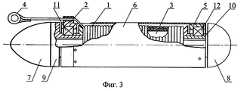
На фиг.3 приведен пример реализации конструкции буксируемой ложной цели. Цифровые обозначения 1, 2, 3, 4, 5 и 6 на фиг.3 соответствуют цифровым обозначениям на фиг.1 и фиг.2. Остальные элементы конструкции на фиг.3: радиопрозрачные обтекатели 7 и 8; основание головного антенного блока 9; основание хвостового антенного блока 10, подшипники 11 и 12. Подшипники 11 и 12 запрессованы в кольцах 2 и 5 и установлены, соответственно, на узких частях оснований антенных блоков 9 и 10, которые жестко соединены с корпусом 3 мишени.Figure 3 shows an example implementation of the towed false target. The
Испытания механизма сматывания подтвердили его работоспособность. Скорость сматывания составляла 8-12 м/с для стального каната диаметром от 1,6 до 3,0 мм.Tests of the winding mechanism confirmed its performance. The winding speed was 8-12 m / s for a steel rope with a diameter of 1.6 to 3.0 mm.
Поскольку обтекатель 6 и дополнительно введенное кольцо 5 механически практически не нагружены, их масса может быть незначительной, и, соответственно, влияние их инерции вращения на скорость сматывания каната несущественно.Since the
Источники информацииSources of information
1 Описание изобретения к патенту Российской Федерации №2067280, F 41 J 9/10, B 64 D 3/02, Бюл. №27, 27.09.96.1 Description of the invention to the patent of the Russian Federation No. 2067280, F 41 J 9/10, B 64
2 Описание изобретения к патенту Российской Федерации №2206049, F 41 J 9/10 (Прототип). Бюл. №16, 10.06.2003.2 Description of the invention to the patent of the Russian Federation No. 2206049, F 41 J 9/10 (Prototype). Bull. No. 16, 06/10/2003.
Claims (1)
Translated fromRussianPriority Applications (1)
| Application Number | Priority Date | Filing Date | Title |
|---|---|---|---|
| RU2004117381/02ARU2263275C1 (en) | 2004-06-07 | 2004-06-07 | Towed false air target |
Applications Claiming Priority (1)
| Application Number | Priority Date | Filing Date | Title |
|---|---|---|---|
| RU2004117381/02ARU2263275C1 (en) | 2004-06-07 | 2004-06-07 | Towed false air target |
Publications (1)
| Publication Number | Publication Date |
|---|---|
| RU2263275C1true RU2263275C1 (en) | 2005-10-27 |
Family
ID=35864311
Family Applications (1)
| Application Number | Title | Priority Date | Filing Date |
|---|---|---|---|
| RU2004117381/02ARU2263275C1 (en) | 2004-06-07 | 2004-06-07 | Towed false air target |
Country Status (1)
| Country | Link |
|---|---|
| RU (1) | RU2263275C1 (en) |
Cited By (3)
| Publication number | Priority date | Publication date | Assignee | Title |
|---|---|---|---|---|
| RU2393420C2 (en)* | 2008-03-11 | 2010-06-27 | Федеральное государственное унитарное предприятие "НИИ "Экран" | Towed air false target |
| RU2401974C1 (en)* | 2009-06-25 | 2010-10-20 | Федеральное государственное унитарное предприятие "НИИ "Экран" | Device for separating, holding and jettisoning towed target |
| CN109437035A (en)* | 2018-12-14 | 2019-03-08 | 河北环航科技股份有限公司 | A kind of speed regulation aeroengine winches |
Citations (5)
| Publication number | Priority date | Publication date | Assignee | Title |
|---|---|---|---|---|
| GB1485354A (en)* | 1975-03-19 | 1977-09-08 | Dornier Gmbh | Aerial towed target |
| US5102145A (en)* | 1991-04-16 | 1992-04-07 | Teledyne Industries, Inc. | Aerial gunnery target system |
| RU2067280C1 (en)* | 1992-12-24 | 1996-09-27 | Акционерное общество открытого типа "Горизонт" | Rope cutter for emergency jettisoning of load from flight vehicle |
| RU2187064C2 (en)* | 2000-03-14 | 2002-08-10 | ОАО "Станкомаш" | Air target |
| RU2206049C1 (en)* | 2001-11-06 | 2003-06-10 | Федеральное государственное унитарное предприятие НИИ "Экран" | Towed aerial false target |
- 2004
- 2004-06-07RURU2004117381/02Apatent/RU2263275C1/ennot_activeIP Right Cessation
Patent Citations (5)
| Publication number | Priority date | Publication date | Assignee | Title |
|---|---|---|---|---|
| GB1485354A (en)* | 1975-03-19 | 1977-09-08 | Dornier Gmbh | Aerial towed target |
| US5102145A (en)* | 1991-04-16 | 1992-04-07 | Teledyne Industries, Inc. | Aerial gunnery target system |
| RU2067280C1 (en)* | 1992-12-24 | 1996-09-27 | Акционерное общество открытого типа "Горизонт" | Rope cutter for emergency jettisoning of load from flight vehicle |
| RU2187064C2 (en)* | 2000-03-14 | 2002-08-10 | ОАО "Станкомаш" | Air target |
| RU2206049C1 (en)* | 2001-11-06 | 2003-06-10 | Федеральное государственное унитарное предприятие НИИ "Экран" | Towed aerial false target |
Cited By (3)
| Publication number | Priority date | Publication date | Assignee | Title |
|---|---|---|---|---|
| RU2393420C2 (en)* | 2008-03-11 | 2010-06-27 | Федеральное государственное унитарное предприятие "НИИ "Экран" | Towed air false target |
| RU2401974C1 (en)* | 2009-06-25 | 2010-10-20 | Федеральное государственное унитарное предприятие "НИИ "Экран" | Device for separating, holding and jettisoning towed target |
| CN109437035A (en)* | 2018-12-14 | 2019-03-08 | 河北环航科技股份有限公司 | A kind of speed regulation aeroengine winches |
Similar Documents
| Publication | Publication Date | Title |
|---|---|---|
| EP3041739B1 (en) | Air-launchable container for deploying air vehicle | |
| EP2276994B1 (en) | Launch system | |
| US5497156A (en) | Towed target | |
| US4149166A (en) | Doppler countermeasure device | |
| DE102015008255B4 (en) | Defense drone to ward off a small drone | |
| US5456427A (en) | Air-launchable gliding sonobuoy | |
| WO1992018825A2 (en) | Aerial gunnery target system with deployment/release system | |
| CN103818527A (en) | Ship short-distance collision avoidance device, umbrella, boat and method | |
| US5368255A (en) | Aerotumbling missile | |
| RU2263275C1 (en) | Towed false air target | |
| US4184681A (en) | Ram-air inflatable, fabric, towed gunnery target | |
| US4356984A (en) | Tow body system-target drone | |
| US6739232B2 (en) | Towed airborne vehicle control and explosion damage assessment | |
| US4649826A (en) | Retardation system for air launched flares and submunitions | |
| RU2206049C1 (en) | Towed aerial false target | |
| RU2339900C1 (en) | Towed false air target | |
| US4852456A (en) | Decoy system | |
| US20140007804A1 (en) | Water parachute for surface vessel motion impedance | |
| US2942545A (en) | Stabilizing system for mine dropped from aircraft | |
| US2892599A (en) | Integrated air-borne towing apparatus | |
| US2932238A (en) | Airborne missile launcher | |
| US11565812B2 (en) | Payload activation device | |
| EP3310661B1 (en) | Aircraft payload launch system | |
| US9897413B1 (en) | Process for launching a cruise missile from an aircraft | |
| US20230349674A1 (en) | Methods and apparatus for drone deployment of non-lethal vehicle stopping countermeasures |
Legal Events
| Date | Code | Title | Description |
|---|---|---|---|
| MM4A | The patent is invalid due to non-payment of fees | Effective date:20060608 | |
| NF4A | Reinstatement of patent | Effective date:20071020 | |
| MM4A | The patent is invalid due to non-payment of fees | Effective date:20110608 |