RU2258805C2 - System for chemical injection into well, oil well for oil product extraction (variants) and oil well operation method - Google Patents
System for chemical injection into well, oil well for oil product extraction (variants) and oil well operation methodDownload PDFInfo
- Publication number
- RU2258805C2 RU2258805C2RU2002126218/03ARU2002126218ARU2258805C2RU 2258805 C2RU2258805 C2RU 2258805C2RU 2002126218/03 ARU2002126218/03 ARU 2002126218/03ARU 2002126218 ARU2002126218 ARU 2002126218ARU 2258805 C2RU2258805 C2RU 2258805C2
- Authority
- RU
- Russia
- Prior art keywords
- chemical
- well
- communication
- container
- oil well
- Prior art date
Links
Images


Classifications
- E—FIXED CONSTRUCTIONS
- E21—EARTH OR ROCK DRILLING; MINING
- E21B—EARTH OR ROCK DRILLING; OBTAINING OIL, GAS, WATER, SOLUBLE OR MELTABLE MATERIALS OR A SLURRY OF MINERALS FROM WELLS
- E21B17/00—Drilling rods or pipes; Flexible drill strings; Kellies; Drill collars; Sucker rods; Cables; Casings; Tubings
- E21B17/003—Drilling rods or pipes; Flexible drill strings; Kellies; Drill collars; Sucker rods; Cables; Casings; Tubings with electrically conducting or insulating means
- E—FIXED CONSTRUCTIONS
- E21—EARTH OR ROCK DRILLING; MINING
- E21B—EARTH OR ROCK DRILLING; OBTAINING OIL, GAS, WATER, SOLUBLE OR MELTABLE MATERIALS OR A SLURRY OF MINERALS FROM WELLS
- E21B34/00—Valve arrangements for boreholes or wells
- E21B34/06—Valve arrangements for boreholes or wells in wells
- E21B34/066—Valve arrangements for boreholes or wells in wells electrically actuated
- E—FIXED CONSTRUCTIONS
- E21—EARTH OR ROCK DRILLING; MINING
- E21B—EARTH OR ROCK DRILLING; OBTAINING OIL, GAS, WATER, SOLUBLE OR MELTABLE MATERIALS OR A SLURRY OF MINERALS FROM WELLS
- E21B34/00—Valve arrangements for boreholes or wells
- E21B34/06—Valve arrangements for boreholes or wells in wells
- E21B34/08—Valve arrangements for boreholes or wells in wells responsive to flow or pressure of the fluid obtained
- E—FIXED CONSTRUCTIONS
- E21—EARTH OR ROCK DRILLING; MINING
- E21B—EARTH OR ROCK DRILLING; OBTAINING OIL, GAS, WATER, SOLUBLE OR MELTABLE MATERIALS OR A SLURRY OF MINERALS FROM WELLS
- E21B34/00—Valve arrangements for boreholes or wells
- E21B34/16—Control means therefor being outside the borehole
- E—FIXED CONSTRUCTIONS
- E21—EARTH OR ROCK DRILLING; MINING
- E21B—EARTH OR ROCK DRILLING; OBTAINING OIL, GAS, WATER, SOLUBLE OR MELTABLE MATERIALS OR A SLURRY OF MINERALS FROM WELLS
- E21B37/00—Methods or apparatus for cleaning boreholes or wells
- E21B37/06—Methods or apparatus for cleaning boreholes or wells using chemical means for preventing or limiting, e.g. eliminating, the deposition of paraffins or like substances
- E—FIXED CONSTRUCTIONS
- E21—EARTH OR ROCK DRILLING; MINING
- E21B—EARTH OR ROCK DRILLING; OBTAINING OIL, GAS, WATER, SOLUBLE OR MELTABLE MATERIALS OR A SLURRY OF MINERALS FROM WELLS
- E21B41/00—Equipment or details not covered by groups E21B15/00 - E21B40/00
- E21B41/02—Equipment or details not covered by groups E21B15/00 - E21B40/00 in situ inhibition of corrosion in boreholes or wells
- E—FIXED CONSTRUCTIONS
- E21—EARTH OR ROCK DRILLING; MINING
- E21B—EARTH OR ROCK DRILLING; OBTAINING OIL, GAS, WATER, SOLUBLE OR MELTABLE MATERIALS OR A SLURRY OF MINERALS FROM WELLS
- E21B43/00—Methods or apparatus for obtaining oil, gas, water, soluble or meltable materials or a slurry of minerals from wells
- E21B43/14—Obtaining from a multiple-zone well
- E—FIXED CONSTRUCTIONS
- E21—EARTH OR ROCK DRILLING; MINING
- E21B—EARTH OR ROCK DRILLING; OBTAINING OIL, GAS, WATER, SOLUBLE OR MELTABLE MATERIALS OR A SLURRY OF MINERALS FROM WELLS
- E21B47/00—Survey of boreholes or wells
- E21B47/12—Means for transmitting measuring-signals or control signals from the well to the surface, or from the surface to the well, e.g. for logging while drilling
- E21B47/13—Means for transmitting measuring-signals or control signals from the well to the surface, or from the surface to the well, e.g. for logging while drilling by electromagnetic energy, e.g. radio frequency
- E—FIXED CONSTRUCTIONS
- E21—EARTH OR ROCK DRILLING; MINING
- E21B—EARTH OR ROCK DRILLING; OBTAINING OIL, GAS, WATER, SOLUBLE OR MELTABLE MATERIALS OR A SLURRY OF MINERALS FROM WELLS
- E21B43/00—Methods or apparatus for obtaining oil, gas, water, soluble or meltable materials or a slurry of minerals from wells
- E21B43/12—Methods or apparatus for controlling the flow of the obtained fluid to or in wells
- E21B43/121—Lifting well fluids
- E21B43/122—Gas lift
- E21B43/123—Gas lift valves
Landscapes
- Engineering & Computer Science (AREA)
- Life Sciences & Earth Sciences (AREA)
- Mining & Mineral Resources (AREA)
- Geology (AREA)
- Physics & Mathematics (AREA)
- General Life Sciences & Earth Sciences (AREA)
- Geochemistry & Mineralogy (AREA)
- Fluid Mechanics (AREA)
- Environmental & Geological Engineering (AREA)
- Remote Sensing (AREA)
- Geophysics (AREA)
- Chemical Kinetics & Catalysis (AREA)
- Mechanical Engineering (AREA)
- Chemical & Material Sciences (AREA)
- Electromagnetism (AREA)
- General Chemical & Material Sciences (AREA)
- Feeding, Discharge, Calcimining, Fusing, And Gas-Generation Devices (AREA)
- Pipeline Systems (AREA)
- Control Of Non-Electrical Variables (AREA)
- Steering Control In Accordance With Driving Conditions (AREA)
- Water Treatment By Electricity Or Magnetism (AREA)
- Lubrication Details And Ventilation Of Internal Combustion Engines (AREA)
Abstract
Description
Translated fromRussianНастоящее изобретение относится к нефтяной скважине для добычи нефтепродуктов. В одном аспекте настоящее изобретение относится к системам и способам для контроля и/или улучшения потока текучей среды во время добычи нефти путем управляемого нагнетания химических реагентов в, по меньшей мере, один поток текучей среды с помощью, по меньшей мере, одной скважинной системы с электрическим управлением для нагнетания химических реагентов скважины.The present invention relates to an oil well for the extraction of petroleum products. In one aspect, the present invention relates to systems and methods for controlling and / or improving the flow of a fluid during oil production by controlled injection of chemicals into at least one fluid stream using at least one downhole electrical system control for injection of chemical reagents wells.
Управляемое нагнетание веществ в нефтяные (т.е. содержащие нефть и газ) скважины является устоявшейся практикой, которая часто используется для увеличения нефтеотдачи или для анализа режима эксплуатации скважины.Controlled injection of substances into oil (i.e., containing oil and gas) wells is a well-established practice that is often used to increase oil recovery or to analyze well operation.
Необходимо различать виды нагнетания в зависимости от количества нагнетаемых веществ. Большие объемы нагнетаемых веществ нагнетают в пласты для обеспечения перемещения пластовых текучих сред по направлению к эксплуатационной скважине. Наиболее характерным примером является заводнение.It is necessary to distinguish the types of injection depending on the amount of injected substances. Large volumes of injected substances are injected into the reservoirs to ensure the movement of reservoir fluids towards the production well. The most characteristic example is water flooding.
Вещества обычно вводят в буровую скважину в местоположение скважины, чтобы произвести обработку внутри буровой скважины. Примеры такой обработки включают следующее:Substances are typically injected into the borehole at the location of the borehole to effect treatment inside the borehole. Examples of such processing include the following:
(1) вспенивающие агенты для повышения эффективности насосно-компрессорной добычи, (2) парафиновые растворители для предотвращения осаждения твердых частиц на насосно-компрессорную колонну, и (3) поверхностно-активные вещества для улучшения характеристик потока добываемых текучих сред. Эти виды обработки приводят к модификации самих текучих сред буровой скважины. Поэтому использовать их необходимо в меньших количествах, и, кроме того, все эти виды нагнетания обычно выполняют с помощью дополнительной трубы, которую направляют с поверхности в скважину.(1) blowing agents to increase the efficiency of pump and compressor production, (2) paraffin solvents to prevent the deposition of solid particles on the tubing string, and (3) surfactants to improve the flow characteristics of the produced fluids. These treatments lead to modification of the borehole fluids themselves. Therefore, they must be used in smaller quantities, and, in addition, all these types of injection are usually performed using an additional pipe, which is sent from the surface to the well.
Однако для других применений требуются даже меньшие количества нагнетаемых веществ, таких как: (1) замедлители коррозии для предотвращения или уменьшения коррозии оборудования буровой скважины, (2) очистители отложений для предотвращения или уменьшения образования осадков в оборудовании буровой скважины, и (3) химические реагенты индикатора для контроля характеристик потока на различных участках буровой скважины. В этих случаях необходимые количества нагнетаемых веществ являются достаточно малыми, поэтому их можно подавать из скважинного продуктивного пласта, что позволяет избежать необходимости подачи этих веществ через насосно-компрессорную трубу в скважину с поверхности. Однако для успешного применения этих методов требуется управляемое нагнетание.However, for other applications, even smaller quantities of injectable substances are required, such as: (1) corrosion inhibitors to prevent or reduce borehole equipment corrosion, (2) scale cleaners to prevent or reduce the formation of deposits in borehole equipment, and (3) chemicals indicator for monitoring flow characteristics in various sections of the borehole. In these cases, the required quantities of injected substances are quite small, so they can be fed from the borehole reservoir, which avoids the need to supply these substances through the tubing to the well from the surface. However, successful application of these methods requires controlled injection.
В патентах США №№4681164, 5246860, 4068717 описано управляемое нагнетание веществ, таких как вода, вспенивающие агенты, парафиновые растворители, поверхностно-активные вещества, замедлители коррозии, вещества, предотвращающие образование отложений, и химические реагенты индикатора, для контроля характеристик потока.US Patent Nos. 4681164, 5246860, 4068717 describe controlled injection of substances such as water, blowing agents, paraffin solvents, surfactants, corrosion inhibitors, scale inhibitors, and indicator chemicals to control flow characteristics.
Все ссылки, представленные здесь, содержат в себе ссылку на максимальный объем изобретения, разрешенный законом. Ссылка на объем изобретения может содержаться здесь не полностью, и она содержит в себе ссылку для второстепенных целей и показывает знания специалистов.All references presented here contain a reference to the maximum scope of the invention permitted by law. A reference to the scope of the invention may not be fully contained here, and it contains a reference for secondary purposes and shows the knowledge of specialists.
Целью настоящего изобретения является устранение вышеуказанных недостатков известных решений.The aim of the present invention is to eliminate the above disadvantages of the known solutions.
В соответствии с настоящим изобретением создана система для нагнетания химических реагентов в скважину, содержащая устройство полного сопротивления по току, предназначенное для размещения вокруг части трубопроводной системы скважины для подачи электрического сигнала, изменяющегося во времени и передаваемого через и вдоль трубопроводной системы, и устройство с электрическим управлением для нагнетания химических реагентов, адаптированное для электрического подсоединения к трубопроводной системе, для подачи питания с помощью электрического сигнала и для вывода химических реагентов в ответ на электрический сигнал.In accordance with the present invention, there is provided a system for injecting chemicals into a well, comprising a current impedance device designed to be placed around a portion of the well’s piping system to provide an electrical signal that varies over time and transmitted through and along the piping system, and an electrically controlled device for injection of chemical reagents, adapted for electrical connection to the piping system, for supplying power by means of an electric signal and for the withdrawal of chemicals in response to an electrical signal.
Трубопроводная система может содержать, по меньшей мере, часть эксплуатационной насосно-компрессорной колонны скважины или, по меньшей мере, часть обсадной колонны скважины.The piping system may comprise at least a portion of a production tubing or at least a portion of a well casing.
Устройство для нагнетания химических реагентов может содержать электродвигатель и модуль связи и управления, причем электродвигатель электрически подсоединен к модулю связи и управления и адаптирован для управления с помощью этого модуля.A device for pumping chemical reagents may include an electric motor and a communication and control module, the electric motor being electrically connected to the communication and control module and adapted for control with this module.
Устройство для нагнетания химических реагентов может содержать клапан с электрическим управлением и модуль связи и управления, причем клапан с электрическим управлением электрически подсоединен к модулю связи и управления и адаптирован для управления с помощью этого модуля.The chemical injection device may include an electrically controlled valve and a communication and control module, wherein the electrically controlled valve is electrically connected to the communication and control module and adapted for control by this module.
Устройство для нагнетания химических реагентов может содержать резервуар для хранения химических реагентов и впрыскиватель химических реагентов, причем резервуар для хранения химических реагентов сообщен с впрыскивателем химических реагентов, и впрыскиватель химических реагентов адаптирован для вывода химических реагентов из резервуара для хранения химических реагентов в ответ на электрический сигнал.A chemical injection device may include a chemical storage tank and a chemical injector, wherein the chemical storage tank is in communication with the chemical injector, and the chemical injector is adapted to discharge chemicals from the chemical storage reservoir in response to an electrical signal.
Электрический сигнал может являться сигналом питания, сигналом связи или сигналом управления, посылаемым из поверхностной компьютерной системы.The electrical signal may be a power signal, a communication signal, or a control signal sent from a surface computer system.
Согласно изобретению создана нефтяная скважина для добычи нефтепродуктов, содержащая трубопроводную систему, размещенную в стволе скважины, источник электрического тока, изменяющегося во времени, электрически подсоединенный к трубопроводной системе, индукционный дроссель, расположенный вокруг части трубопроводной системы, устройство с электрическим управлением для нагнетания химических реагентов, связанное с трубопроводной системой для приема питания и сигналов связи через электрический ток, изменяющийся во времени, и приспособленное для впрыскивания химических реагентов.According to the invention, an oil well for producing oil products is created, comprising a pipeline system located in the wellbore, a time-varying electric current source electrically connected to the pipeline system, an induction inductor located around a portion of the pipeline system, an electrically controlled device for pumping chemical reagents, associated with a piping system for receiving power and communication signals through an electric current that varies over time, and adapted Goes for the injection of chemicals.
Индукционный дроссель может быть неподключенным к электропитанию и может содержать ферромагнитный материал для обеспечения функционирования индукционного дросселя с учетом своего размера, геометрии, пространственных соотношений с трубопроводной системой и магнитных свойств.The induction inductor may not be connected to the power supply and may contain ferromagnetic material to ensure the functioning of the induction inductor, taking into account its size, geometry, spatial relationships with the piping system and magnetic properties.
Трубопроводная система может содержать, по меньшей мере, часть эксплуатационной насосно-компрессорной колонны, и цепь обратного тока содержит по меньшей мере часть обсадной колонны скважины.The piping system may comprise at least a portion of the production tubing and the return circuit includes at least a portion of the well casing.
Трубопроводная система может содержать, по меньшей мере, часть обсадной колонны скважины.The piping system may comprise at least a portion of the well casing.
Устройство для нагнетания химических реагентов может содержать клапан с электрическим управлением или электродвигатель, или модем, или датчик.The device for pumping chemicals may include an electrically controlled valve or an electric motor, or a modem, or a sensor.
Устройство для нагнетания химических реагентов может содержать резервуар для хранения химических реагентов. Резервуар для хранения химических реагентов может быть приспособлен для впрыскивания химических реагентов в трубопроводную систему.The chemical injection device may include a chemical storage tank. The chemical storage tank may be adapted to inject chemicals into the piping system.
Согласно изобретению создана нефтяная скважина для добычи нефтепродуктов, содержащая обсадную колонну, проходящую в стволе скважины, эксплуатационную насосно-компрессорную колонну, проходящую в обсадной колонне, источник электрического тока, изменяющегося во времени, расположенный на поверхности, электрически подсоединенный и адаптированный для вывода электрического тока, изменяющегося во времени, в, по меньшей мере, насосно-компрессорную колонну или обсадную колонну, и скважинное устройство для нагнетания химических реагентов, содержащее модуль связи и управления, контейнер с химическим реагентом и впрыскиватель химических реагентов с электрическим управлением, при этом модуль связи и управления электрически подсоединен к, по меньшей мере, насосно-компрессорной колонне или обсадной колонне для приема оттуда электрического тока, изменяющегося во времени, впрыскиватель химических реагентов электрически подсоединен к модулю связи и управления, и контейнер с химическим реагентом сообщен с впрыскивателем химических реагентов.According to the invention, an oil well for producing petroleum products is created, comprising a casing string passing in the wellbore, a production tubing running in the casing string, a time-varying electric current source located on the surface, electrically connected and adapted to output electric current, time-varying in at least the tubing or casing, and the downhole device for pumping chemicals, soda a holding communication and control module, a container with a chemical reagent and an electrically controlled chemical injector; the communication and control module is electrically connected to at least a tubing or casing to receive from there an electric current that varies over time, the injector The chemical reagent is electrically connected to the communication and control module, and the container with the chemical reagent is in communication with the chemical injector.
Впрыскиватель химических реагентов может содержать электродвигатель, винтовой механизм и сопло, причем электродвигатель электрически соединен с модулем связи и управления, винтовой механизм механически связан с электродвигателем, а сопло проходит в насосно-компрессорную колонну и обеспечивает проход для текучей среды между контейнером с химическим реагентом и внутренней частью насосно-компрессорной колонны, и винтовой механизм приспособлен для вытеснения текучей среды из контейнера с химическим реагентом в насосно-компрессорную колонну через сопло в ответ на вращательное движение электродвигателя.The chemical injector may comprise an electric motor, a screw mechanism and a nozzle, wherein the electric motor is electrically connected to the communication and control module, the screw mechanism is mechanically connected to the electric motor, and the nozzle passes into the tubing string and provides a passage for the fluid between the chemical container and the internal part of the tubing string, and the screw mechanism is adapted to displace fluid from a container with a chemical reagent into the tubing the column through the nozzle in response to the rotational movement of the electric motor.
Впрыскиватель химических реагентов может содержать газовый баллон, заполненный газом под давлением, регулятор давления, клапан с электрическим управлением и сопло, при этом внутренняя часть контейнера с химическим реагентом содержит сепаратор, образующий первый объем для содержания химических реагентов и второй объем, причем газовый баллон сообщен со вторым объемом контейнера с химическим реагентом через регулятор давления так, что газ под давлением может находиться во втором объеме и вне первого объема для оказания давления на химический реагент в первом объеме, при этом клапан с электрическим управлением электрически соединен с модулем связи и управления для получения из него питания и сигналов команд управления, и клапан с электрическим управлением адаптирован для регулировки и управления прохождением химических реагентов из первого объема через сопло и в насосно-компрессорную колонну.The chemical injector may comprise a gas cylinder filled with gas under pressure, a pressure regulator, an electrically controlled valve and a nozzle, wherein the inside of the chemical container comprises a separator forming a first volume for containing the chemical reagents and a second volume, the gas cylinder being in communication with the second volume of the container with the chemical agent through the pressure regulator so that the gas under pressure can be in the second volume and outside the first volume to exert pressure on the chemical The reagent is in the first volume, while the electrically controlled valve is electrically connected to the communication and control module to receive power and control command signals from it, and the electrically controlled valve is adapted to regulate and control the passage of chemicals from the first volume through the nozzle and into the pump compressor column.
Контейнер с химическим реагентом может содержать сепаратор, расположенный в нем и делящий внутреннюю часть контейнера на два объема, впрыскиватель химических реагентов содержит клапан с электрическим управлением и сопло, причем первый объем контейнера с химическим реагентом содержит химический реагент, второй объем контейнера с химическим реагентом содержит газ под давлением для оказания газом давления на химический реагент в первом объеме, при этом клапан с электрическим управлением электрически соединен с модулем связи и управления и управляется с помощью этого модуля, и первый объем сообщен с внутренней частью насосно-компрессорной колонны через клапан с электрическим управлением и через сопло.The chemical reagent container may comprise a separator located therein and dividing the interior of the container into two volumes, the chemical injector comprises an electrically controlled valve and a nozzle, the first volume of the chemical reagent container containing the chemical reagent, the second volume of the chemical reagent container containing gas under pressure to apply gas pressure to the chemical in the first volume, while the electrically controlled valve is electrically connected to the communication module and controlled I is controlled by this module, and a first volume in communication with the interior of the tubing string through an electrically controllable valve and a nozzle.
Контейнер с химическим реагентом может содержать сепаратор, делящий внутреннюю часть контейнера с химическим реагентом на два объема, впрыскиватель химических реагентов содержит клапан с электрическим управлением и сопло, причем первый объем контейнера с химическим реагентом содержит химический реагент, а второй объем контейнера с химическим реагентом содержит пружинный элемент для воздействия на химический реагент в первом объеме, при этом клапан с электрическим управлением электрически соединен с модулем связи и управления и управляется с помощью этого модуля, и первый объем сообщен с внутренней частью насосно-компрессорной колонны через клапан с электрическим управлением и через сопло.The chemical reagent container may comprise a separator dividing the inside of the chemical reagent container into two volumes, the chemical injector comprises an electrically controlled valve and a nozzle, the first volume of the chemical reagent container containing a chemical reagent and the second volume of the chemical reagent container containing a spring an element for influencing the chemical reagent in the first volume, wherein the electrically controlled valve is electrically connected to the communication and control module and control is injected using this module, and the first volume is communicated with the inside of the tubing string through an electrically controlled valve and through a nozzle.
Контейнер с химическим реагентом может быть адаптирован для удержания в нем химического реагента под давлением, впрыскиватель химических реагентов содержит клапан с электрическим управлением и сопло, причем клапан с электрическим управлением электрически соединен с модулем связи и управления и управляется с помощью этого модуля, а сопло проходит во внутреннюю часть насосно-компрессорной колонны, при этом контейнер с химическим реагентом сообщен с внутренней частью насосно-компрессорной колонны через клапан с электрическим управлением и через сопло.A container with a chemical reagent can be adapted to hold the chemical reagent in it under pressure, the chemical injector contains an electrically controlled valve and a nozzle, the electrically controlled valve being electrically connected to the communication and control module and controlled by this module, and the nozzle passes through the inner part of the tubing string, while the container with the chemical reagent is in communication with the inner part of the tubing string through an electrically controlled valve it and through the nozzle.
Впрыскиватель химических реагентов может содержать электродвигатель, насос, односторонний клапан и сопло, причем электродвигатель электрически подсоединен к модулю связи и управления и управляется с помощью этого модуля, насос механически связан с электродвигателем, и сопло проходит во внутреннюю часть насосно-компрессорной колонны, при этом контейнер с химическим реагентом сообщен с внутренней частью насосно-компрессорной колонны через насос, односторонний клапан и сопло.The chemical injector may comprise an electric motor, a pump, a one-way valve and a nozzle, the electric motor being electrically connected to the communication and control module and controlled by this module, the pump is mechanically connected to the electric motor, and the nozzle passes into the inside of the tubing string, and the container with a chemical reagent communicated with the inside of the tubing string through the pump, one-way valve and nozzle.
Нефтяная скважина может дополнительно содержать трубопровод для подачи химических реагентов, проходящий с поверхности в скважинное устройство для нагнетания химических реагентов, контейнер с химическим реагентом содержит канал для прохождения текучей среды, соединяющий трубопровод для подачи химических реагентов с внутренней частью насосно-компрессорной колонны через впрыскиватель химических реагентов.An oil well may further comprise a chemical supply pipe extending from the surface to the chemical injection device, the chemical container contains a fluid passage connecting the chemical supply pipe to the inside of the tubing string through the chemical injector .
Контейнер с химическим реагентом может дополнительно содержать резервуар для хранения химических реагентов.The chemical reagent container may further comprise a chemical storage tank.
Контейнер с химическим реагентом может содержать автономный скважинный резервуар для текучей среды, адаптированный для подачи химического реагента для скважинного устройства для нагнетания химических реагентов.The chemical reagent container may comprise a stand-alone downhole fluid reservoir adapted to supply a chemical reagent to a downhole chemical injection device.
Нефтяная скважина может содержать индукционный дроссель, неподключенный к электропитанию и содержащий ферромагнитный материал.An oil well may comprise an induction choke that is not connected to power and contains ferromagnetic material.
Контейнер с химическим реагентом может быть приспособлен для рассеивания химических реагентов в, по меньшей мере, насосно-компрессорную колонну или обсадную колонну.The chemical reagent container may be adapted to disperse the chemical reagents into at least a tubing or casing.
Контейнер с химическим реагентом может быть приспособлен для рассеивания химических реагентов в геологической формации вне обсадной колонны.The chemical container may be adapted to disperse the chemicals in the geological formation outside the casing.
Скважинное устройство для нагнетания химических реагентов может дополнительно содержать датчик, электрически подсоединенный к модулю связи и управления.The downhole chemical injection device may further comprise a sensor electrically connected to the communication and control module.
Модуль связи и управления может содержать модем.The communication and control module may comprise a modem.
Согласно изобретению создан способ управления нефтяной скважиной, оборудованной трубопроводной системой и подсоединенной к ней в местоположении скважины скважинной системой для нагнетания химических реагентов для буровой скважины, содержащий следующие этапы: передача сигнала переменного электрического тока посредством использования индукционного дросселя по трубопроводной системе для питания и связи со скважинной системой для нагнетания химических реагентов; адаптирование скважинной системы для нагнетания химических реагентов в скважину в ответ на сигнал переменного электрического тока; нагнетание химических реагентов в скважинный поток с возможностью управления нагнетанием в ответ на сигнал переменного электрического тока во время добычи.According to the invention, a method for controlling an oil well equipped with a pipeline system and connected to it at the location of the well with a downhole system for injecting chemicals for the well, comprising the following steps: transmitting an AC signal by using an induction inductor through the pipeline system for power and communication with the downhole chemical injection system; adapting the downhole system to inject chemicals into the well in response to an alternating current signal; injection of chemicals into the well stream with the ability to control injection in response to an alternating electric current signal during production.
В качестве скважины можно использовать газлифтную скважину, можно использовать химический реагент, содержащий вспенивающий агент, и дополнительно осуществлять повышение эффективности насосно-компрессорной добычи нефтепродуктов с помощью вспенивающего агента.As a well, you can use a gas lift well, you can use a chemical reagent containing a blowing agent, and additionally increase the efficiency of pumping of oil products using a blowing agent.
Можно использовать химический реагент, содержащий парафиновый растворитель, и трубопроводную систему, включающую насосно-компрессорную колонну, и дополнительно осуществлять сдерживание осаждения твердых частиц на внутренней части насосно-компрессорной колонны.You can use a chemical reagent containing a paraffin solvent, and a piping system including a tubing string, and further inhibit the deposition of solid particles on the inside of the tubing string.
Можно использовать химический реагент, содержащий поверхностно-активное вещество, и дополнительно осуществлять улучшение характеристики протекающего потока.You can use a chemical reagent containing a surfactant, and in addition to improve the characteristics of the flowing stream.
Можно использовать химический реагент, содержащий замедлитель коррозии, и дополнительно осуществлять замедление коррозии в стволе скважины.You can use a chemical reagent containing a corrosion inhibitor, and in addition to slow down corrosion in the wellbore.
Можно использовать химический реагент, содержащий вещества, предотвращающие образование отложений, и дополнительно осуществлять уменьшение образования отложений в скважине.You can use a chemical reagent containing substances that prevent the formation of deposits, and further reduce the formation of deposits in the well.
Можно использовать химический реагент, содержащий состав для гидравлического разрыва пласта, и дополнительно осуществлять нагнетание этого состава в геологическую формацию, расположенную вокруг буровой скважины.You can use a chemical reagent containing a composition for hydraulic fracturing, and in addition to carry out the injection of this composition into the geological formation located around the borehole.
Другие цели и преимущества изобретения приведены в следующем подробном описании со ссылками на сопроводительные чертежи, на которых изображено следующее:Other objectives and advantages of the invention are given in the following detailed description with reference to the accompanying drawings, which depict the following:
фиг.1 изображает схему нефтяной эксплуатационной скважины, согласно предпочтительному варианту осуществления настоящего изобретения;figure 1 depicts a diagram of an oil production well, according to a preferred embodiment of the present invention;
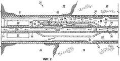
фиг.2 изображает в увеличенном масштабе нижнюю часть буровой скважины, показанной на фиг.1;figure 2 depicts on an enlarged scale the lower part of the borehole shown in figure 1;
фиг.3 изображает упрощенную электрическую схему электрической цепи, образованной буровой скважиной, показанной на фиг.1;figure 3 depicts a simplified circuit diagram of an electrical circuit formed by the borehole shown in figure 1;
фиг.4A-4F изображают различные схемы вариантов осуществления впрыскивателя химических реагентов и контейнера с химическим реагентом для скважинного устройства с электрическим управлением для нагнетания химических реагентов, согласно настоящему изобретению.4A-4F depict various diagrams of embodiments of a chemical injector and a chemical container for an electrically controlled downhole apparatus for pumping chemicals according to the present invention.
Ниже приводится описание предпочтительного варианта осуществления настоящего изобретения со ссылкой на чертежи, на которых одинаковые позиции обозначают одинаковые элементы на всех различных видах, и описание других возможных вариантов осуществления настоящего изобретения. Представленные фигуры не обязательно выполнены в масштабе, и в некоторых случаях чертежи увеличены и/или упрощены в определенных местах для удобства изображения. Специалисты могут оценить многие возможные применения и изменения настоящего изобретения на основании приведенных здесь примеров возможных вариантов осуществления настоящего изобретения, а также на основании тех вариантов осуществления, изображенных и обсужденных в родственных заявках, которые включены здесь в качестве ссылки в максимальной степени, разрешенной законом.The following is a description of a preferred embodiment of the present invention with reference to the drawings, in which like numbers denote like elements in all different views, and other possible embodiments of the present invention. The presented figures are not necessarily made to scale, and in some cases, the drawings are enlarged and / or simplified in certain places for the convenience of the image. Skilled artisans will appreciate many of the possible uses and variations of the present invention based on the examples of possible embodiments of the present invention given here, as well as on those embodiments depicted and discussed in related applications, which are incorporated herein by reference to the maximum extent permitted by law.
Термин "трубопроводная система", используемый в настоящей заявке, может представлять собой одну единственную трубу, насосно-компрессорную колонну, обсадную колонну буровой скважины, насосную штангу, ряд взаимосвязанных труб, буровые штанги, фермы, решетки сквозной фермы, опоры, отводные или боковые удлинители скважины, сеть соединенных между собой труб или других подобных систем, известных специалистам. В предпочтительном варианте осуществления изобретение используется трубопроводная система, размещенная в стволе скважины, содержит трубчатую, металлическую, электропроводную трубу или насосно-компрессорную колонну, но изобретение не ограничено этим. Для настоящего изобретения, по меньшей мере, часть трубопроводной системы должна быть электропроводной, при этом такая электропроводная часть может представлять собой в целом трубопроводную систему (например, стальные трубы, медные трубы) или проходящую в продольном направлении электропроводную часть, объединенную с проходящей в продольном направлении неэлектропроводной частью. Другими словами, электропроводная трубопроводная система представляет собой систему, которая обеспечивает путь электрического тока от первой части, при этом источник питания электрически подсоединен ко второй части, где устройство и/или цепь обратного тока электрически подсоединена. Трубопроводная система обычно представляет собой известную круглую металлическую насосно-компрессорную колонну, но геометрия поперечного сечения трубопроводной системы или любой ее части может изменяться по форме (например, круглая, прямоугольная, квадратная, овальная) и по размеру (например, длина, диаметр, толщина стенки) вдоль любой части трубопроводной системы. Следовательно, трубопроводная система должна иметь электропроводную часть, проходящую от первой части трубопроводной системы до второй части трубопроводной системы, в которой первая часть расположена отдельно от второй части вдоль трубопроводной системы.The term "pipe system" used in this application may be one single pipe, tubing, casing, borehole, a number of interconnected pipes, drill rods, trusses, through truss lattices, supports, outlets or side extensions wells, a network of interconnected pipes or other similar systems known to those skilled in the art. In a preferred embodiment, the invention uses a pipeline system located in the wellbore, comprising a tubular, metal, electrical conductive pipe or tubing, but the invention is not limited to this. For the present invention, at least a portion of the piping system must be electrically conductive, wherein such an electrically conductive part may be a whole piping system (e.g., steel pipes, copper pipes) or a longitudinally extending electrically conductive portion combined with a longitudinally extending non-conductive part. In other words, the electrically conductive piping system is a system that provides an electric current path from the first part, wherein the power source is electrically connected to the second part, where the device and / or the reverse current circuit is electrically connected. The pipe system is usually a well-known round metal tubing, but the cross-sectional geometry of the pipe system or any part thereof can vary in shape (e.g., round, rectangular, square, oval) and in size (e.g. length, diameter, wall thickness ) along any part of the pipeline system. Therefore, the pipeline system must have an electrically conductive part extending from the first part of the pipeline system to the second part of the pipeline system, in which the first part is located separately from the second part along the pipeline system.
Термины "первая часть" и "вторая часть", которые используются здесь, означают, в общем, часть, секцию или область трубопроводной системы, которая может проходить или не проходить вдоль трубопроводной системы, которая может быть расположена в любом выбранном месте вдоль трубопроводной системы, и которая может охватывать или не охватывать наиболее близкие концы трубопроводной системы.The terms "first part" and "second part" as used herein mean, in general, a part, section or region of a pipeline system that may or may not extend along the pipeline system, which may be located at any selected location along the pipeline system, and which may or may not include the closest ends of the pipeline system.
Термин "модем" используется здесь, в общем, для ссылки на любое устройство связи для передачи и/или приема электрических сигналов связи через электрический проводник (например, металл). Следовательно, термин "модем", который используется здесь, не ограничен акронимом для модулятора (устройства, которое преобразовывает голос или сигнал данных к виду, пригодному для передачи)/демодулятора (устройства, которое восстанавливает первоначальный сигнал, которым была промодулирована высокочастотная несущая). Кроме того, термин "модем", который используется здесь, не ограничен известными компьютерными модемами, которые преобразовывают цифровые сигналы в аналоговые сигналы и наоборот (например, для передачи цифровых информационных сигналов по аналоговой коммутируемой телефонной сети общего пользования). Например, если датчик выдает данные измерений в аналоговой форме, то такие измерения необходимо только модулировать (например, с использованием модуляции с расширением спектра) и передавать, и, следовательно, не нужно выполнять аналого-цифрового преобразования. В качестве другого примера, релейный/подчиненный модем или устройство связи могут только идентифицировать, фильтровать, усиливать и/или ретранслировать принимаемый сигнал.The term "modem" is used here, in General, to refer to any communication device for transmitting and / or receiving electrical communication signals through an electrical conductor (for example, metal). Therefore, the term “modem” as used here is not limited to the acronym for modulator (device that converts a voice or data signal to a form suitable for transmission) / demodulator (device that restores the original signal with which the high frequency carrier was modulated). In addition, the term “modem” as used herein is not limited to known computer modems that convert digital signals to analog signals and vice versa (for example, to transmit digital information signals over an analogue public switched telephone network). For example, if a sensor provides measurement data in analog form, then such measurements only need to be modulated (for example, using spread spectrum modulation) and transmitted, and therefore there is no need for analog-to-digital conversion. As another example, a relay / slave modem or communication device can only identify, filter, amplify and / or relay a received signal.
Термин "клапан", который используется здесь, относится к любому устройству, которое выполняет функции регулировки потока текучей среды. Примеры клапанов включают, но не ограничивают сильфонные газлифтные клапаны и управляемые газлифтные клапаны, каждый из которых можно использовать для регулировки потока транспортирующего газа в колонну насосно-компрессорных труб буровой скважины. Внутренняя работа клапанов может в значительной степени отличаться, и в настоящей заявке не ограничиваются клапанами, описанными с любой конкретной конфигурацией, до тех пор, пока клапан выполняет функции регулировки потока текучей среды. Некоторые из различных типов механизмов регулировки потока включают, но не ограничивают конфигурации шарового клапана, конфигурации игольчатого клапана, конфигурации запорного клапана и конфигурации клетевого клапана. Способы установки клапанов, обсужденных в настоящей заявке, могут изменяться в широких пределах.The term “valve,” as used herein, refers to any device that performs the functions of adjusting fluid flow. Examples of valves include, but are not limited to, bellows gas lift valves and controlled gas lift valves, each of which can be used to control the flow of carrier gas into the tubing string of the borehole. The internal operation of the valves may vary significantly, and in this application are not limited to the valves described with any particular configuration, as long as the valve has the function of adjusting the flow of fluid. Some of the various types of flow control mechanisms include, but are not limited to, ball valve configurations, needle valve configurations, shutoff valve configurations, and cage valve configurations. The valve installation methods discussed in this application can vary widely.
Термин "клапан с электрическим управлением", который используется здесь, обычно относится к "клапану" (как описано выше), который можно открывать, закрывать, регулировать, изменять или дросселировать непрерывно в ответ на электрический сигнал управления (например, сигнал из поверхностного компьютера или из скважинного модуля электронного контроллера). Механизм, который фактически изменяет состояние клапана, может содержать, но не ограничивать электродвигатель, электрический серводвигатель, электрический соленоид, электрический переключатель, гидравлический привод, управляемый, по меньшей мере, одним электрическим серводвигателем, электродвигателем, электрическим переключателем, электрическим соленоидом или их комбинациями, пневматический привод, управляемый, по меньшей мере, одним электрическим серводвигателем, электродвигателем, электрическим переключателем, электрическим соленоидом или их комбинациями, или устройство с отклоняемой пружиной в комбинации с, по меньшей мере, одним электрическим серводвигателем, электродвигателем, электрическим переключателем, электрическим соленоидом или их комбинациями. "Клапан с электрическим управлением" может включать или не включать датчик положения с обратной связью для подачи сигнала обратной связи, соответствующего фактическому положению клапана.The term “electrically controlled valve”, as used herein, generally refers to a “valve” (as described above) that can be opened, closed, controlled, changed or throttled continuously in response to an electrical control signal (eg, a signal from a surface computer or from the borehole module of the electronic controller). A mechanism that actually changes the state of the valve may include, but not be limited to, an electric motor, an electric servomotor, an electric solenoid, an electric switch, a hydraulic actuator controlled by at least one electric servomotor, an electric motor, an electric switch, an electric solenoid, or combinations thereof, pneumatic drive controlled by at least one electric servomotor, electric motor, electric switch, electric a Lenoid or combinations thereof, or a deflectable spring device in combination with at least one electric servomotor, an electric motor, an electric switch, an electric solenoid, or combinations thereof. An “electrically controlled valve” may or may not include a position feedback sensor to provide a feedback signal corresponding to the actual position of the valve.
Термин "датчик", который используется здесь, относится к любому устройству, который обнаруживает, определяет, контролирует, записывает или, другими словами, регистрирует абсолютное значение или изменение значения физической величины. Датчик, как описано здесь, можно использовать для измерения значений таких физических величин, но не ограничено этим, как температура, давление (абсолютное и дифференциальное), скорость потока, сейсмические данные, акустические данные, уровень рН, уровни солености, положения клапана или практически любые другие физические данные.The term “sensor,” as used herein, refers to any device that detects, detects, monitors, records, or, in other words, records an absolute value or a change in a value of a physical quantity. The sensor, as described here, can be used to measure values of such physical quantities, but not limited to, such as temperature, pressure (absolute and differential), flow rate, seismic data, acoustic data, pH, salinity levels, valve positions, or almost any other physical data.
Термин "беспроводный", который используется в настоящей заявке, означает отсутствие известного, изолированного электрического провода, например, проходящего из скважинного устройства на поверхность. Использование насосно-компрессорной колонны и/или обсадной колонны в качестве проводника рассматривается как "беспроводным".The term "wireless", as used in this application, means the absence of a known, insulated electrical wire, for example, passing from the downhole device to the surface. The use of a tubing and / or casing as a conductor is considered “wireless”.
Фраза "на поверхности", которая используется здесь, относится к местоположению, которое проходит от поверхности земли на глубину приблизительно пятидесяти и более футов. Другими словами, фраза "на поверхности" не обязательно означает расположение на уровне поверхности земли, а используется здесь в более широком смысле для обозначения местоположения, которое является обычно легкодоступным или удобным в устье скважины, где могут работать люди. Например, "на поверхности" может означать на столе в рабочей мастерской, которая расположена на поверхности земли на платформе буровой скважины, на дне океана или озера, на глубоководной платформе нефтяной вышки или на 100-м этаже здания. Кроме того, термин "поверхность" может использоваться здесь как прилагательное для определения местоположения элемента или области, которая расположена "на поверхности". Например, фраза "поверхностный" компьютер, которая используется здесь, означает компьютер, расположенный "на поверхности".The phrase “on the surface,” as used herein, refers to a location that extends from the surface of the earth to a depth of approximately fifty or more feet. In other words, the phrase "on the surface" does not necessarily mean a location at ground level, but is used here in a broader sense to indicate a location that is usually easily accessible or convenient at the wellhead where people can work. For example, “on the surface” may mean on a table in a workshop that is located on the surface of the earth on a borehole platform, on the bottom of an ocean or lake, on a deep-water platform of an oil rig or on the 100th floor of a building. In addition, the term “surface” can be used here as an adjective to determine the location of an element or region that is located “on the surface”. For example, the phrase “surface” computer that is used here means a computer located “on the surface”.
Термин "скважинный", который используется здесь, относится к местоположению или положению на глубине около пятидесяти футов или ниже от поверхности земли. Другими словами, термин "скважинный", широко используемый здесь, относится к местоположению, которое обычно трудно или неудобно достигнуть из устья скважины, где могут работать люди. Например, в нефтяной скважине, "скважинное" местоположение находится часто в или рядом с подземной нефтяной эксплуатационной зоной, независимо от того, является ли эксплуатационная зона доступной вертикально, горизонтально, сбоку или под любым другим углом между ними. Кроме того, термин "скважинный" используется здесь как прилагательное, описывающее местоположение элемента или области. Например, "скважинное" устройство в буровой скважине означает, что устройство расположено "в скважине", а не "на поверхности".The term “downhole” as used herein refers to a location or position at a depth of about fifty feet or lower from the surface of the earth. In other words, the term “downhole,” as used broadly herein, refers to a location that is usually difficult or inconvenient to reach from the wellhead where people can work. For example, in an oil well, the "well" location is often in or near the underground oil production zone, regardless of whether the production zone is accessible vertically, horizontally, sideways, or at any other angle between them. In addition, the term "downhole" is used here as an adjective describing the location of an element or area. For example, a “borehole” device in a borehole means that the device is located “in the borehole” and not “on the surface”.
Аналогично, в соответствии с известной терминологией, употребляемой в практике нефтяного промысла, определения "верхний", "нижний", "вверх по стволу скважины" и "скважинный" являются относительными и касаются расстояния, измеренного вдоль ствола скважины вглубь от поверхности земли, которое в наклонных или горизонтальных скважинах может или нет совпадать с вертикальной проекцией, измеренной по отношению к данным наблюдений.Similarly, in accordance with the well-known terminology used in the practice of the oil field, the definitions of “upper”, “lower”, “up the borehole” and “borehole” are relative and relate to the distance measured along the borehole deep from the surface of the earth, which deviated or horizontal wells may or may not coincide with the vertical projection, measured in relation to the observational data.
На фиг.1 изображена схема, показывающая нефтяную эксплуатационную скважину 20, согласно предпочтительному варианту осуществления настоящего изобретения. Буровая скважина 20 имеет вертикальную секцию 22 и боковую секцию 26. Буровая скважина имеет обсадную колонну 30 буровой скважины, проходящую в стволах скважины и через геологическую формацию 32, и эксплуатационная насосно-компрессорная колонна 40 проходит в обсадной колонне буровой скважины для транспортировки текучих сред во время добычи из скважины на поверхность. Следовательно, нефтяная эксплуатационная скважина 20, показанная на фиг.1, подобна известной буровой скважине по конструкции, но с учетом настоящего изобретения.1 is a diagram showing an oil production well 20 according to a preferred embodiment of the present invention. The
Вертикальная секция 22 в настоящем варианте осуществления включает газлифтный клапан 42 и верхний пакер 44 для обеспечения искусственного подъема текучих сред по насосно-компрессорной колонне 40. Однако альтернативные варианты осуществления могут включать и другие способы обеспечения искусственного подъема текучих сред для образования других возможных вариантов осуществления (например, эксплуатация скважин штанговым насосом). Кроме того, вертикальная часть 22 может в дальнейшем измениться для образования многих других возможных вариантов осуществления. Например, в общем виде вертикальная часть 22 может включать один или несколько газлифтных клапанов с электрическим управлением, один или несколько дополнительных индукционных дросселей и/или один или несколько управляемых пакеров, содержащих пакерные клапаны с электрическим управлением, как дополнительно описано в родственных заявках.The vertical section 22 in the present embodiment includes a gas lift valve 42 and an upper packer 44 for artificially lifting the fluids along the
Боковая секция 26 буровой скважины 20 проходит через нефтяную эксплуатационную зону 48 (например, нефтеносная зона) геологической формации 32. Обсадную колонну 30 в боковой секции 26 перфорируют для обеспечения протекания текучих сред из эксплуатационной зоны 48 в обсадную колонну. На фиг.1 показана только одна боковая секция 26, но в ней может быть много боковых ответвлений буровой скважины 20. Конфигурация буровой скважины обычно зависит, по меньшей мере, частично от расположения эксплуатационных зон для данной геологической формации.The
Часть насосно-компрессорной колонны 40 проходит в боковую секцию 26 и завершается закрытым концом 52 за эксплуатационной зоной 48. Положение конца 52 насосно-компрессорной колонны в обсадной колонне 30 поддерживается боковым пакером 54, который является известным пакером. Насосно-компрессорная колонна 40 имеет перфорированную секцию 56 для забора текучей среды из эксплуатационной зоны 48. В других вариантах осуществления (не показано), насосно-компрессорная колонна 40 может проходить за пределы эксплуатационной зоны 48 (например, в другие эксплуатационные зоны), или насосно-компрессорная колонна 40 может завершаться открытым концом для притока текучей среды.A portion of the
Скважинное устройство 60 с электрическим управлением для нагнетания химических реагентов соединено последовательно с насосно-компрессорной колонной 40 внутри боковой секции 26 (вверх по течению) эксплуатационной зоны 48 и образует часть сборки эксплуатационной насосно-компрессорной колонны. В альтернативном варианте, устройство 60 для нагнетания можно разместить дальше вверх по течению внутри боковой секции 26. Преимуществом размещения устройства 60 для нагнетания рядом с заборником 56 насосно-компрессорной колонны в эксплуатационной зоне 48 является то, что желательное местоположение для нагнетания индикатора (для контроля потока в насосно-компрессорной колонне в этой эксплуатационной зоне) или для нагнетания вспенивающего агента (для повышения производительности газлифта). В других возможных вариантах осуществления, устройство 60 для нагнетания можно адаптировать для управляемого нагнетания химического реагента или вещества в местоположение вне насосно-компрессорной колонны 40 (например, непосредственно в эксплуатационной зоне 48 или в кольцевом пространстве 62 внутри обсадной колонны 30). Кроме того, скважинное устройство 60 с электрическим управлением для нагнетания химических реагентов можно разместить, при необходимости, в любом скважинном местоположении внутри буровой скважины.An electrically controlled
Электрическая цепь образуется с использованием различных элементов буровой скважины 20. Питание для электрических элементов устройства 60 для нагнетания подается с поверхности с использованием насосно-компрессорной колонны 40 и обсадной колонны 30 в качестве электрических проводников. Следовательно, в предпочтительном варианте осуществления, насосно-компрессорная колонна 40 действует как трубопроводная система, и обсадная колонна 30 действует как цепь обратного тока для образования электрической цепи в буровой скважине 20. Кроме того, насосно-компрессорная колонна 40 и обсадная колонна 30 используются в качестве электрических проводников для сигналов связи между поверхностью (например, поверхностной компьютерной системой) и скважинными электрическими элементами внутри скважинного устройства 60 с электрическим управлением для нагнетания химических реагентов.An electrical circuit is formed using various elements of the
На фиг.1 поверхностная компьютерная система 64 содержит главный модем 66 и источник 68 тока, изменяющегося во времени. Однако, как будет ясно специалистам, поверхностное оборудование может изменяться. Первый вывод 71 компьютера поверхностной компьютерной системы 64 электрически подсоединен к насосно-компрессорной колонне 40 на поверхности, и обеспечивает передачу электрического тока, изменяющегося во времени, в насосно-компрессорную колонну 40, когда необходимо питание и/или связь со скважинными устройствами. Источник 68 электрического тока обеспечивает подачу электрического тока, который несет в себе питание и сигналы связи в скважине. Электрический ток, изменяющийся во времени, предпочтительно является переменным током, но он может быть также и изменяющимся во времени постоянным током. Сигналы связи можно вырабатывать с помощью главного модема 66 и передавать с помощью тока, произведенного источником 68. Сигнал связи, предпочтительно, является сигналом с расширенным спектром, но в альтернативе можно использовать и другие формы модуляции или предыскажения.1, a surface computer system 64 comprises a main modem 66 and a time-varying
Первый индукционный дроссель 74 расположен вокруг насосно-компрессорной колонны в вертикальной секции 22 ниже местоположения, где боковая секция 26 проходит от вертикальной секции. Второй индукционный дроссель 90 расположен вокруг насосно-компрессорной колонны 40 внутри боковой секции 26 рядом с устройством 60 для нагнетания. Индукционные дроссели 74, 90 содержат ферромагнитный материал и не подключены к питанию. Так как дроссели 74, 90 расположены вокруг насосно-компрессорной колонны 40, каждый из них действует как большая катушка индуктивности для переменного тока в цепи буровой скважины, образованной с помощью насосно-компрессорной колонны 40 и обсадной колонны 30. Как описано подробно в родственных заявках, работа дросселей 74, 90 зависит от их размера (массы), геометрической конфигурации и магнитных свойств.The
Изолирующая соединительная муфта 76 для насосно-компрессорных труб расположена в устье скважины, обеспечивая электрическую изоляцию насосно-компрессорной колонны 40 от обсадной колонны 30. Первый вывод 71 компьютера из источника 68 тока проходит через изолирующую прокладку 77 в подвеске 88 и электрически подсоединен к насосно-компрессорной колонне 40 ниже изолирующей соединительной муфты 76 для насосно-компрессорных труб. Второй вывод 72 компьютера поверхностной компьютерной системы 64 электрически подсоединен к обсадной колонне 30 на поверхности. Таким образом, изоляторы 79 соединительной муфты 76 для насосно-компрессорных труб предотвращают короткое замыкание между насосно-компрессорной колонной 40 и обсадной колонной 30 на поверхности. В альтернативе к или в дополнение к изолирующей соединительной муфте 76 для насосно-компрессорных труб, третий индукционный дроссель (не показан) можно разместить вокруг насосно-компрессорной колонны 40 выше местоположения электрического соединения для первого вывода 71 компьютера с насосно-компрессорной колонной, и/или подвеска 88 может представлять собой подвесной изолятор (не показан), имеющий изоляторы для электрической изоляции насосно-компрессорной колонны 40 от обсадной колонны 30.An isolating coupling 76 for tubing is located at the wellhead, providing electrical isolation of the
Боковой пакер 54 на конце 52 насосно-компрессорной колонны внутри боковой секции 26 обеспечивает электрическое соединение между насосно-компрессорной колонной 40 и обсадной колонной 30 в скважине за вторым дросселем 90. Нижний пакер 78 в вертикальной секции 22, который является также известным пакером, обеспечивает электрическое соединение между насосно-компрессорной колонной 40 и обсадной колонной 30 в скважине ниже первого индукционного дросселя 74. Верхний пакер 44 вертикальной секции 22 имеет электрический изолятор 79 для того, чтобы предотвратить короткое замыкание между насосно-компрессорной колонной 40 и обсадной колонной 30 в верхнем пакере. Кроме того, различные центраторы (не показаны), имеющие электрические изоляторы для предотвращения короткого замыкания между насосно-компрессорной колонной 40 и обсадной колонной 30 можно, при необходимости, ввести по всей буровой скважине 20. Такую электрическую изоляцию верхнего 44 пакера или центратора можно достигнуть различными способами, которые известны специалистам. Верхний и нижний пакеры 44, 78 обеспечивают гидравлическую изоляцию между главным стволом скважины вертикальной секции 22 и боковым стволом скважины боковой секции 26.The
На фиг.2 показана в увеличенном масштабе часть боковой секции 26 (фиг.1) с расположенным в ней скважинным устройством 60 с электрическим управлением для нагнетания химических реагентов. Устройство 60 для нагнетания содержит модуль связи и управления, контейнер 82 с химическим реагентом и впрыскиватель 84 химических реагентов. Все элементы скважинного устройства 60 с электрическим управлением для нагнетания химических реагентов, предпочтительно, содержатся вместе в одном герметичном коллекторе 86 насосно-компрессорной колонны в виде одного модуля для упрощения обработки и установки, а также для защиты элементов от воздействия окружающей среды. Однако в других вариантах осуществления настоящего изобретения, элементы скважинного устройства 60 с электрическим управлением для нагнетания химических реагентов можно разделить (то есть, отсутствует коллектор 86 насосно-компрессорной колонны) или объединены в другие комбинации. Первый вывод 91 устройства 60 для нагнетания электрически подсоединен между насосно-компрессорной колонной 40 на стороне 94 источника второго индукционного дросселя 90 и модулем 80 связи и управления. Второй вывод 92 устройства 60 для нагнетания электрически подсоединен между насосно-компрессорной колонной 40 на стороне 96 цепи обратного тока второго индукционного дросселя 90 и модулем 80 связи и управления. Хотя боковой пакер 54 обеспечивает электрическое соединение между насосно-компрессорной колонной 40 на стороне 96 цепи обратного тока второго индукционного дросселя 90 и обсадной колонной 30, при этом электрическое соединение между насосно-компрессорной колонной 40 и обсадной колонной 30 буровой скважины можно также выполнить многочисленными способами, некоторые из которых представлены в родственных заявках настоящего заявителя и включают в себя (но не ограничивают) другой пакер (известный или управляемый), проводящий центратор, проводящий флюид в кольце между насосно-компрессорной колонной и обсадной колонной буровой скважины, или любую их комбинацию.FIG. 2 shows, on an enlarged scale, a portion of the side section 26 (FIG. 1) with an electrically controlled
На фиг.3 изображена упрощенная электрическая схема, иллюстрирующая электрическую цепь, образованную в буровой скважине 20 (фиг.1). В процессе работы, питание и/или сигналы связи подают в насосно-компрессорную колонну 40 на поверхности через первый вывод 71 компьютера ниже изоляционной соединительной муфты 76 для насосно-компрессорных труб. Протеканию тока, изменяющегося во времени, из насосно-компрессорной колонны 40 в обсадную колонну 30 через подвеску 88 препятствуют изоляторы 79 изоляционной соединительной муфты 76 для насосно-компрессорных труб. Однако ток, изменяющийся во времени, свободно протекает вдоль насосно-компрессорной колонны 40 до достижения индукционных дросселей 74, 90. Первый индукционный дроссель 74 имеет большую индуктивность, которая препятствует протеканию большей части тока через насосно-компрессорную колонну 40 с первым индукционным дросселем. Аналогично, второй индукционный дроссель 90 имеет большую индуктивность, которая препятствует протеканию большей части тока через насосно-компрессорную колонну 40 со вторым индукционным дросселем. Разность потенциалов возникает между насосно-компрессорной колонной 40 и обсадной колонной 30 благодаря индукционным дросселям 74, 90. Разность потенциалов также возникает между насосно-компрессорной колонной 40 на стороне 94 источника второго индукционного дросселя 90 и насосно-компрессорной колонной 40 на стороне 96 цепи обратного тока второго индукционного дросселя 90. Так как модуль 80 связи и управления электрически подсоединен параллельно напряжению, большая часть электрического тока, переданного в насосно-компрессорную колонну 40, которая не потерялась по пути, направляется через модуль 80 связи и управления, который распределяет и/или декодирует питание и/или сигналы связи для устройства 60 для нагнетания. После прохождения через устройство 60 для нагнетания, ток возвращается в поверхностную компьютерную систему 64 через боковой пакер 54 и обсадную колонну 30. Когда ток является электрическим переменным током, направление протекания тока будет меняться на обратное, и он будет проходить через буровую скважину 20 вдоль того же самого пути.FIG. 3 is a simplified circuit diagram illustrating an electrical circuit formed in a borehole 20 (FIG. 1). In the process, power and / or communication signals are supplied to the
Другие альтернативные способы усовершенствования электрической цепи с использованием трубопроводной системы буровой скважины и, по меньшей мере, один индукционный дроссель описаны в родственных заявках настоящего заявителя, многие из которых можно применять совместно с настоящим изобретением для подачи питания и/или сигналов связи в скважинные устройства, подключенные к электропитанию, и формировать другие варианты осуществления настоящего изобретения.Other alternative methods for improving the electrical circuit using a borehole piping system and at least one induction choke are described in the related applications of the present applicant, many of which can be used in conjunction with the present invention to supply power and / or communication signals to downhole devices connected to power, and form other embodiments of the present invention.
Как показано на фиг.2, модуль 80 связи и управления содержит, по отдельности, адресуемый модем 100, схемы 102 регулирования питания, интерфейс 104 управления и интерфейс 106 датчиков. С помощью датчиков 108, расположенных внутри устройства 60 для нагнетания, производят измерения, например, скорости потока, температуры, давления или концентрации веществ индикаторов, и эти данные кодируют внутри модуля 80 связи и управления и передают с помощью модема 100 в поверхностную компьютерную систему 64. Так как модем 100 скважинного устройства 60 для нагнетания имеет индивидуальную адресацию, то можно установить более одного скважинного устройства и использовать их независимо от других.As shown in FIG. 2, the communication and control module 80 comprises, individually, an
На фиг.2 впрыскиватель 84 химических реагентов электрически подсоединен к модулю 80 связи и управления, и таким образом получает питание и/или сигналы связи из поверхностной компьютерной системы 64 через модуль 80 связи и управления. Контейнер 82 с химическим реагентом связан по каналу для прохождения флюида с впрыскивателем 84 химических реагентов. Контейнер 82 с химическим реагентом является автономным резервуаром для хранения химических реагентов, который обеспечивает хранение и подачу химических реагентов для впрыскивания в протекающий поток с помощью впрыскивателя химических реагентов. Контейнер 82 с химическим реагентом (фиг.2) не имеет трубопроводной системы, проходящей с поверхности, для подачи химических реагентов. Следовательно, размер резервуара для хранения химических реагентов может изменяться в зависимости от объема химических реагентов, необходимых для впрыскивания в буровую скважину. В действительности размер контейнера 82 с химическим реагентом может быть весьма большим, если он размещается в части буровой скважины меньшего диаметра ("крысиная дыра"). Впрыскиватель 84 химических реагентов предпочтительного варианта осуществления содержит электродвигатель 110, винтовой механизм 112 и сопло 114. Электродвигатель 110 электрически подсоединен к и принимает из модуля 80 связи и управления сигналы команд на выполнение движения. Сопло 114 простирается во внутреннюю часть 116 насосно-компрессорной колонны 40 и обеспечивает проход флюида из контейнера 82 с химическим реагентом во внутреннюю часть 116 насосно-компрессорной колонны. Винтовой механизм 112 механически связан с электродвигателем 110. Винтовой механизм 112 используется для вытеснения химических реагентов из контейнера 82 во внутреннюю часть 116 насосно-компрессорной колонны через сопло 114 в ответ на вращательное движение электродвигателя 110. Электродвигатель 110, предпочтительно, является шаговым электродвигателем, и таким образом обеспечивает впрыскивание химических реагентов с возрастающим количеством.2, the
В процессе работы поток текучей среды из эксплуатационной зоны 48 проходит через устройство 60 для нагнетания химических реагентов, так как он течет через насосно-компрессорную колонну 40 на поверхность. Команды из поверхностной компьютерной системы 64 передают в скважину и принимают с помощью модема 100 модуля связи и управления. Команды декодируются в устройстве 60 для нагнетания и проходят из модема 100 в интерфейс 104 управления. Интерфейс 104 управления затем подает команды в электродвигатель 110 для его запуска и нагнетания определенного количества химических реагентов из контейнера 82 в поток флюида, протекающий в насосно-компрессорной колонне 40. Следовательно, устройство 60 для нагнетания вводит химические реагенты в поток флюида, протекающий в насосно-компрессорной колонне 40 в ответ на команды, подаваемые из поверхностной компьютерной системы 64 через модуль 80 связи и управления. В случае вспенивающего агента, вспенивающий агент впрыскивается в насосно-компрессорную колонну 40 с помощью устройства 60 для нагнетания химических реагентов способом, необходимым для улучшения характеристик потока и/или подъема в буровой скважине 20.During operation, a fluid stream from operating
Как будет ясно специалистам, механическое и электрическое размещение и конфигурация элементов в устройстве 60 с электрическим управлением для нагнетания химических реагентов можно изменить при сохранении тех же самых выполняемых функций обеспечения электрически управляемого нагнетания химических реагентов в скважине. Например, устройство модуля 80 связи и управления может быть очень простым, как вывод соединительного провода для распределения электрических соединений из насосно-компрессорной колонны 40, или может быть очень сложным, содержащим (но не ограниченным) модем, аккумулятор, силовой трансформатор, микропроцессор, память, схему сбора данных и схему управления движением.As will be appreciated by those skilled in the art, the mechanical and electrical placement and configuration of the elements in the electrically controlled
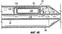
На фиг.4A-4G изображены некоторые возможные разновидности контейнера 82 с химическим реагентом и впрыскивателя 84 химических реагентов, который может быть включен в состав настоящего изобретения для образования других возможных вариантов осуществления. На фиг.4А впрыскиватель 84 химических реагентов содержит баллон 118 с газом под давлением, регулятор 120 давления, клапан 122 с электрическим управлением и сопло 114. Баллон 118 с газом под давлением сообщен с контейнером 82 с химическим реагентом через регулятор 120 давления, и таким образом обеспечивает подачу газа, в общем, с постоянным давлением в резервуар для хранения химических реагентов. Контейнер 82 с химическим реагентом имеет камеру 124, которая содержит химические реагенты. Регулятор 120 давления регулирует прохождение газа под давлением, подаваемого из баллона 118 в контейнер 82, но вне камеры 124. Однако регулятор 120 давления можно заменить на клапан с электрическим управлением. Газ под давлением оказывает давление на камеру 124 и, таким образом, на химические реагенты, находящиеся в ней. Клапан 122 с электрическим управлением регулирует и управляет прохождением химических реагентов через сопло 114 и во внутреннюю часть насосно-компрессорной колонны 116. Так как химические реагенты внутри камеры 124 находятся под давлением газа, подаваемого из баллона 118, химические реагенты вытесняются из сопла 114, когда клапан 122 с электрическим управлением открыт.4A-4G show some possible variations of a
На фиг.4В контейнер 82 с химическим реагентом разделен на два объема 126, 128 с помощью камеры 124, которая действует как сепаратор между этими двумя объемами 126, 128. Первый объем 126 внутри камеры 124 содержит химические реагенты, второй объем 128 внутри контейнера 82 с химическим реагентом, но вне камеры содержит газ под давлением. Следовательно, контейнер 82 предварительно заряжен, и газ под давлением оказывает давление на химические реагенты внутри камеры 124. Впрыскиватель 84 химических реагентов содержит клапан 122 с электрическим управлением и сопло 114. Клапан 122 с электрическим управлением электрически подсоединен к и управляется с помощью модуля 80 связи и управления. Клапан 122 с электрическим управлением регулирует и управляет прохождением химических реагентов через сопло 114 и во внутреннюю часть 116 насосно-компрессорной колонны. Химические реагенты вытесняются из сопла 114 за счет давления газа, когда клапан 122 с электрическим управлением открыт.4B, the
Вариант осуществления, показанный на фиг.4С, подобен варианту осуществления, показанному на фиг.4В, но на камеру 124 оказывает давление пружинный элемент 130. Кроме того, на фиг.4С камера может отсутствовать, если между пружинным элементом 130 и химическими реагентами внутри контейнера 82 с химическим реагентом находится передвижная прокладка (например, герметичный поршень). Специалистам будет ясно, что может существовать много разновидностей механической конструкции впрыскивателя 84 химических реагентов и вариантов использования пружинного элемента для оказания давления на химические реагенты.The embodiment shown in FIG. 4C is similar to the embodiment shown in FIG. 4B, but the
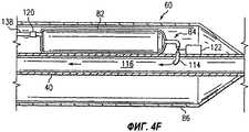
На фиг.4D контейнером 82 с химическим реагентом является баллон под давлением, содержащий химический реагент, который представляет собой текучую среду под давлением. Впрыскиватель 84 химических реагентов содержит клапан 122 с электрическим управлением и сопло 114. Клапан 122 с электрическим управлением регулирует и управляет прохождением химических реагентов через сопло 114 и во внутреннюю часть 116 насосно-компрессорной колонны. Так как химические реагенты в контейнере 82 находятся под давлением, химические реагенты вытесняются из сопла 114, когда клапан 122 с электрическим управлением открыт.4D, the
На фиг.4Е контейнер 82 с химическим реагентом имеет камеру 124, содержащую химический реагент. Впрыскиватель 84 химических реагентов содержит насос 134, односторонний клапан 136, сопло 114 и электродвигатель 110. Насос 134 приводится в действие с помощью электродвигателя 110, который электрически подсоединен к модулю 80 связи и управления, и управляется с помощью этого модуля 80. Односторонний клапан 136 предотвращает противоток в насос 134 и камеру 124. Насос 134 вытесняет химические реагенты из камеры 124 через односторонний клапан 136 из сопла 114 и во внутреннюю часть 116 насосно-компрессорной колонны. Следовательно, использование впрыскивателя 84 химических реагентов (фиг.4Е) может быть выгодно в случае, где резервуар для хранения химических реагентов или контейнер 82 произвольно сформированы для получения максимального объема химических реагентов, удерживаемых в нем для заданной конфигурации, потому что конфигурация резервуара для хранения химических реагентов не зависит от реализованной конфигурации впрыскивателя 84 химических реагентов.4E, the
На фиг.4F показан вариант осуществления настоящего изобретения, где трубопровод 138 для подачи химических реагентов проходит в скважинное местоположение в устройство 60 для нагнетания химических реагентов с поверхности. Такой вариант осуществления можно использовать в случае, где имеется потребность нагнетания большого количества химических реагентов во внутреннюю часть 116 насосно-компрессорной колонны. Контейнер 82 с химическим реагентом (фиг.4F) предусматривает как канал для прохождения текучей среды, соединяющий трубопровод 138 для подачи химических реагентов со впрыскивателем 84 химических реагентов, так и резервуар для хранения некоторых химических реагентов в скважине. Кроме того, скважинный контейнер 82 может представлять собой только канал для прохождения флюида или соединитель (отсутствует характерный объем контейнера) между трубопроводом 138 для подачи химических реагентов и впрыскивателем 84 химических реагентов для подачи сыпучего впрыскиваемого вещества с поверхности необходимым способом.FIG. 4F shows an embodiment of the present invention where a
Таким образом, варианты, представленные на фиг.4A-4F, показывают, что существует много возможных разновидностей контейнера 82 с химическим реагентом и впрыскивателя 84 химических реагентов. Специалистам будет ясно, что может быть гораздо больше разновидностей выполнения функции подачи, хранения и/или содержания химических реагентов в скважине в комбинации с управляемым впрыскиванием химического реагента во внутреннюю часть 116 насосно-компрессорной колонны в ответ на подачу электрического сигнала. Изменения (не показаны) впрыскивателя 84 химических реагентов могут дополнительно включать в себя (но не ограничивать): трубку Вентури в сопле, давление на камере, созданное с помощью турбоустройства, создающего энергию вращения из потока текучей среды внутри насосно-компрессорной колонны, создание давления из других областей геологической формации, которое направляется через насосно-компрессорную колонну, любую возможную комбинацию частей фиг.4A-4F или любую их комбинацию.Thus, the options shown in figa-4F show that there are many possible varieties of the
Кроме того, устройство 60 для нагнетания не может впрыскивать химические реагенты во внутреннюю часть 116 насосно-компрессорной колонны. Другими словами, устройство для нагнетания химических реагентов можно адаптировать к управляемому нагнетанию химических реагентов в геологическую формацию 32, в обсадную колонну 30, или непосредственно в эксплуатационную зону 48. Кроме того, продление насосно-компрессорной колонны (не показано) может проходить от сопла впрыскивателя химических реагентов до области, отдаленной от устройства для нагнетания химических реагентов (например, дальше в местоположение скважины или глубоко в эксплуатационную зону).In addition, the
Устройство 60 для нагнетания может дополнительно содержать и другие элементы для образования других возможных вариантов осуществления настоящего изобретения, включая (но не ограничивая): датчик, электродвигатель, модем, микропроцессор, логическую схему, электрически управляемый клапан насосно-компрессорной колонны, многочисленные резервуары для хранения химических реагентов (которые могут содержать различные химические реагенты) или любую их комбинацию. Резервуар может быть приспособлен для впрыскивания химических реагентов. Нагнетаемыми химическими реагентами могут быть твердые частицы, жидкость, газ или их смеси. Нагнетаемые химические реагенты могут быть однокомпонентными и многокомпонентными или иметь сложный состав. Кроме того, можно использовать многочисленные управляемые устройства для нагнетания химических реагентов для одной или более боковых секций, каждое из которых может иметь независимый доступ, групповой доступ или одинаковый доступ из поверхностной компьютерной системы 64. В альтернативе, для управления с помощью поверхностной компьютерной системы 64 скважинным устройством 60 с электрическим управлением для нагнетания химических реагентов можно управлять с помощью электронной схемы, размещенной в нем, или с помощью другого скважинного устройства. Аналогично, скважинным устройством 60 с электрическим управлением для нагнетания химических реагентов можно управлять и/или поддерживать связь с помощью других скважинных устройств. В публикации WO 01/65055 использовано скважинное устройство 60 с электрическим управлением для нагнетания химических реагентов, в заявке РСТ US 01/0695 использован один или несколько датчиков 108, каждый из которых адаптирован для измерения физической величины, такой как (но не ограничено) абсолютное давление, дифференциальное давление, плотность текучей среды, вязкость текучей среды, звукопроницаемость или отражательные свойства, температура или химический состав.The
После обзора родственных заявок настоящего заявителя специалисты могут заметить, что можно использовать и другие скважинные устройства с электрическим управлением, а также как многочисленные индукционные дроссели, дополнительно включенные в. буровую скважину для образования других возможных вариантов осуществления настоящего изобретения. Такие другие скважинные устройства с электрическим управлением включают (но не ограничиваются): один или несколько управляемых пакеров, имеющих электрически управляемые клапаны пакера, один или несколько электрически управляемых газлифтных клапанов, один или несколько модемов, один или несколько датчиков, микропроцессор, логическую схему, один или несколько электрически управляемых клапанов насосно-компрессорной колонны для управления потоком из различных боковых ответвлений и, при необходимости, другие электронные элементы.After reviewing the related applications of the present applicant, specialists may notice that other electrically controlled downhole devices can be used, as well as numerous induction chokes further included in. a borehole to form other possible embodiments of the present invention. Such other electrically controlled downhole devices include, but are not limited to: one or more controlled packers having electrically controlled packer valves, one or more electrically controlled gas lift valves, one or more modems, one or more sensors, a microprocessor, a logic circuit, one or several electrically controlled valves of the tubing string to control the flow from various side branches and, if necessary, other electronic elements.
Настоящее изобретение можно также применить и к другим типам буровых скважин (отличающихся от нефтяных скважин), таких как водозаборная скважина.The present invention can also be applied to other types of boreholes (other than oil wells), such as a water well.
Специалистам будет ясно, что настоящее изобретение предусматривает нефтяную эксплуатационную скважину, имеющую, по меньшей мере, одно устройство с электрическим управлением для нагнетания химических реагентов, а также способы использования таких устройств для контроля и/или улучшения эксплуатационных характеристик буровой скважины. Следует понимать, что чертежи и подробное описание приведены здесь в иллюстративных, а не в ограничительных целях, и не предназначены для ограничения изобретения конкретными формами и раскрытыми примерами. Напротив, изобретение включает в себя любые дополнительные модификации, изменения, перестановки, замены, альтернативные варианты, выбор конструкции и варианты осуществления, ясные специалистам, без отклонения от сущности и масштаба настоящего изобретения, определенного в следующей ниже формуле изобретения. Таким образом, подразумевается, что следующая ниже формула изобретения охватывает все такие дополнительные модификации, изменения, перестановки, замены, альтернативные варианты, выбор конструкции и варианты осуществления.It will be clear to those skilled in the art that the present invention provides an oil production well having at least one electrically controlled device for pumping chemicals, as well as methods for using such devices to monitor and / or improve the performance of a borehole. It should be understood that the drawings and detailed description are given here for illustrative and not restrictive purposes, and are not intended to limit the invention to the specific forms and disclosed examples. On the contrary, the invention includes any additional modifications, changes, permutations, replacements, alternative options, design choices and embodiments that are clear to those skilled in the art without departing from the spirit and scope of the present invention as defined in the following claims. Thus, it is intended that the following claims cover all such additional modifications, changes, permutations, replacements, alternatives, design choices, and embodiments.
Claims (41)
Translated fromRussianApplications Claiming Priority (2)
| Application Number | Priority Date | Filing Date | Title |
|---|---|---|---|
| US18638100P | 2000-03-02 | 2000-03-02 | |
| US60/186,381 | 2000-03-02 |
Publications (2)
| Publication Number | Publication Date |
|---|---|
| RU2002126218A RU2002126218A (en) | 2004-02-20 |
| RU2258805C2true RU2258805C2 (en) | 2005-08-20 |
Family
ID=22684724
Family Applications (1)
| Application Number | Title | Priority Date | Filing Date |
|---|---|---|---|
| RU2002126218/03ARU2258805C2 (en) | 2000-03-02 | 2001-03-02 | System for chemical injection into well, oil well for oil product extraction (variants) and oil well operation method |
Country Status (11)
| Country | Link |
|---|---|
| US (1) | US6981553B2 (en) |
| EP (1) | EP1259701B1 (en) |
| AU (2) | AU2001243413B2 (en) |
| BR (1) | BR0108881B1 (en) |
| CA (1) | CA2401681C (en) |
| DE (1) | DE60119898T2 (en) |
| MX (1) | MXPA02008577A (en) |
| NO (1) | NO325380B1 (en) |
| OA (1) | OA12225A (en) |
| RU (1) | RU2258805C2 (en) |
| WO (1) | WO2001065055A1 (en) |
Cited By (4)
| Publication number | Priority date | Publication date | Assignee | Title |
|---|---|---|---|---|
| RU2398098C1 (en)* | 2009-06-03 | 2010-08-27 | Закрытое Акционерное Общество "Новомет-Пермь" | Method for even supply of liquid reagent into well |
| RU2446272C1 (en)* | 2011-01-31 | 2012-03-27 | Закрытое Акционерное Общество "Новомет-Пермь" | Well dosed reagent supply device |
| RU2535546C1 (en)* | 2013-08-20 | 2014-12-20 | Открытое акционерное общество "Татнефть" имени В.Д. Шашина | Device for scale prevention in well |
| RU2559977C1 (en)* | 2014-07-29 | 2015-08-20 | Акционерное общество "Новомет-Пермь" (АО "Новомет-Пермь") | Device for supply of inhibitor into well |
Families Citing this family (80)
| Publication number | Priority date | Publication date | Assignee | Title |
|---|---|---|---|---|
| AU5836701A (en) | 2000-04-24 | 2001-11-07 | Shell Int Research | In situ recovery of hydrocarbons from a kerogen-containing formation |
| US6929067B2 (en) | 2001-04-24 | 2005-08-16 | Shell Oil Company | Heat sources with conductive material for in situ thermal processing of an oil shale formation |
| AU2002360301B2 (en)* | 2001-10-24 | 2007-11-29 | Shell Internationale Research Maatschappij B.V. | In situ thermal processing and upgrading of produced hydrocarbons |
| AU2003285008B2 (en)* | 2002-10-24 | 2007-12-13 | Shell Internationale Research Maatschappij B.V. | Inhibiting wellbore deformation during in situ thermal processing of a hydrocarbon containing formation |
| US20040084186A1 (en)* | 2002-10-31 | 2004-05-06 | Allison David B. | Well treatment apparatus and method |
| WO2004097159A2 (en) | 2003-04-24 | 2004-11-11 | Shell Internationale Research Maatschappij B.V. | Thermal processes for subsurface formations |
| US7410002B2 (en)* | 2003-08-05 | 2008-08-12 | Stream-Flo Industries, Ltd. | Method and apparatus to provide electrical connection in a wellhead for a downhole electrical device |
| US7552762B2 (en)* | 2003-08-05 | 2009-06-30 | Stream-Flo Industries Ltd. | Method and apparatus to provide electrical connection in a wellhead for a downhole electrical device |
| ATE392534T1 (en) | 2004-04-23 | 2008-05-15 | Shell Int Research | PREVENTION OF RETURN IN A HEATED COUNTER OF AN IN-SITU CONVERSION SYSTEM |
| US7311144B2 (en) | 2004-10-12 | 2007-12-25 | Greg Allen Conrad | Apparatus and method for increasing well production using surfactant injection |
| US7243726B2 (en)* | 2004-11-09 | 2007-07-17 | Schlumberger Technology Corporation | Enhancing a flow through a well pump |
| US20060185840A1 (en)* | 2005-02-23 | 2006-08-24 | Conrad Greg A | Apparatus for monitoring pressure using capillary tubing |
| US7500528B2 (en) | 2005-04-22 | 2009-03-10 | Shell Oil Company | Low temperature barrier wellbores formed using water flushing |
| DE602006013437D1 (en) | 2005-04-22 | 2010-05-20 | Shell Int Research | A TEMPERATURE-LIMITED HEATING DEVICE USING A NON-FERROMAGNETIC LADDER |
| KR101434259B1 (en) | 2005-10-24 | 2014-08-27 | 쉘 인터내셔날 리써취 마트샤피지 비.브이. | Cogeneration systems and processes for treating hydrocarbon containing formations |
| EA007551B1 (en)* | 2006-02-01 | 2006-10-27 | Рафаил Минигулович Минигулов | Method and system for injecting inhibitors of hydro-forming during production and preparing hydrocarbon feed to transporting and storing |
| EP2010755A4 (en) | 2006-04-21 | 2016-02-24 | Shell Int Research | HEATING SEQUENCE OF MULTIPLE LAYERS IN A FORMATION CONTAINING HYDROCARBONS |
| GB2461362A (en) | 2006-10-20 | 2010-01-06 | Shell Int Research | Systems and processes for use in treating subsurface formations |
| CN101688442B (en) | 2007-04-20 | 2014-07-09 | 国际壳牌研究有限公司 | Molten salt as a heat transfer fluid for heating a subsurface formation |
| RU2496067C2 (en) | 2007-10-19 | 2013-10-20 | Шелл Интернэшнл Рисерч Маатсхаппий Б.В. | Cryogenic treatment of gas |
| US7842738B2 (en)* | 2007-10-26 | 2010-11-30 | Conocophillips Company | High polymer content hybrid drag reducers |
| US7888407B2 (en) | 2007-10-26 | 2011-02-15 | Conocophillips Company | Disperse non-polyalphaolefin drag reducing polymers |
| US20090209679A1 (en)* | 2008-02-14 | 2009-08-20 | Conocophillips Company | Core-shell flow improver |
| US20090260823A1 (en)* | 2008-04-18 | 2009-10-22 | Robert George Prince-Wright | Mines and tunnels for use in treating subsurface hydrocarbon containing formations |
| GB2462480B (en) | 2008-06-07 | 2012-10-17 | Camcon Ltd | Gas injection control devices and methods of operation thereof |
| EP2361343A1 (en) | 2008-10-13 | 2011-08-31 | Shell Oil Company | Using self-regulating nuclear reactors in treating a subsurface formation |
| WO2010118315A1 (en) | 2009-04-10 | 2010-10-14 | Shell Oil Company | Treatment methodologies for subsurface hydrocarbon containing formations |
| US8430162B2 (en)* | 2009-05-29 | 2013-04-30 | Schlumberger Technology Corporation | Continuous downhole scale monitoring and inhibition system |
| US8607868B2 (en) | 2009-08-14 | 2013-12-17 | Schlumberger Technology Corporation | Composite micro-coil for downhole chemical delivery |
| US8136594B2 (en)* | 2009-08-24 | 2012-03-20 | Halliburton Energy Services Inc. | Methods and apparatuses for releasing a chemical into a well bore upon command |
| US9103199B2 (en)* | 2009-12-31 | 2015-08-11 | Baker Hughes Incorporated | Apparatus and method for pumping a fluid and an additive from a downhole location into a formation or to another location |
| US8602658B2 (en)* | 2010-02-05 | 2013-12-10 | Baker Hughes Incorporated | Spoolable signal conduction and connection line and method |
| US8397828B2 (en)* | 2010-03-25 | 2013-03-19 | Baker Hughes Incorporated | Spoolable downhole control system and method |
| US8820406B2 (en) | 2010-04-09 | 2014-09-02 | Shell Oil Company | Electrodes for electrical current flow heating of subsurface formations with conductive material in wellbore |
| US9033042B2 (en) | 2010-04-09 | 2015-05-19 | Shell Oil Company | Forming bitumen barriers in subsurface hydrocarbon formations |
| US8631866B2 (en) | 2010-04-09 | 2014-01-21 | Shell Oil Company | Leak detection in circulated fluid systems for heating subsurface formations |
| US8701768B2 (en) | 2010-04-09 | 2014-04-22 | Shell Oil Company | Methods for treating hydrocarbon formations |
| US8905128B2 (en)* | 2010-07-20 | 2014-12-09 | Schlumberger Technology Corporation | Valve assembly employable with a downhole tool |
| GB2484692B (en)* | 2010-10-20 | 2016-03-23 | Camcon Oil Ltd | Fluid injection device |
| US8910714B2 (en)* | 2010-12-23 | 2014-12-16 | Schlumberger Technology Corporation | Method for controlling the downhole temperature during fluid injection into oilfield wells |
| US20120292044A1 (en)* | 2011-02-03 | 2012-11-22 | Patel Dinesh R | Telemetric chemical injection assembly |
| US9016370B2 (en) | 2011-04-08 | 2015-04-28 | Shell Oil Company | Partial solution mining of hydrocarbon containing layers prior to in situ heat treatment |
| RU2472922C1 (en)* | 2011-07-12 | 2013-01-20 | Закрытое Акционерное Общество "Новомет-Пермь" | Well reagent supply device |
| WO2013034184A1 (en)* | 2011-09-08 | 2013-03-14 | Statoil Petroleum As | A method and an arrangement for controlling fluid flow into a production pipe |
| CA2850741A1 (en) | 2011-10-07 | 2013-04-11 | Manuel Alberto GONZALEZ | Thermal expansion accommodation for circulated fluid systems used to heat subsurface formations |
| US10047594B2 (en) | 2012-01-23 | 2018-08-14 | Genie Ip B.V. | Heater pattern for in situ thermal processing of a subsurface hydrocarbon containing formation |
| AU2012367826A1 (en) | 2012-01-23 | 2014-08-28 | Genie Ip B.V. | Heater pattern for in situ thermal processing of a subsurface hydrocarbon containing formation |
| RU2493359C1 (en)* | 2012-03-22 | 2013-09-20 | Открытое акционерное общество "Нефтяная компания "Роснефть" | Pump packer assembly for dual pumping of two beds |
| EA201400316A1 (en)* | 2012-04-11 | 2014-09-30 | Общество с ограниченной ответственностью "Виатех" | COMPLEX OF EQUIPMENT FOR EXTRACTION OF HIGH-LANGUAGE OIL |
| US20140000889A1 (en)* | 2012-06-28 | 2014-01-02 | Baker Hughes Incorporated | Wireline flow through remediation tool |
| BR122020007387B1 (en)* | 2012-09-26 | 2021-09-14 | Halliburton Energy Services, Inc | SENSING ARRANGEMENT FOR USE IN A WELL HOLE, SENSING SYSTEM AND METHOD FOR MEASURING AT LEAST ONE PARAMETER IN A WELL HOLE |
| WO2014107113A1 (en)* | 2013-01-02 | 2014-07-10 | Scale Protection As | Scale indication device and method |
| RU2524579C1 (en)* | 2013-04-05 | 2014-07-27 | Открытое акционерное общество "Татнефть" имени В.Д. Шашина | Device to force reagent into well |
| WO2015050993A1 (en) | 2013-10-01 | 2015-04-09 | FlowCore Systems, LLC | Fluid metering system |
| US10472255B2 (en) | 2013-10-01 | 2019-11-12 | FlowCore Systems, LLC | Fluid metering system |
| US9745975B2 (en) | 2014-04-07 | 2017-08-29 | Tundra Process Solutions Ltd. | Method for controlling an artificial lifting system and an artificial lifting system employing same |
| CN105822274A (en)* | 2015-01-09 | 2016-08-03 | 中国石油天然气股份有限公司 | Horizontal well process pipe column |
| CN105822257B (en)* | 2015-01-09 | 2018-12-28 | 中国石油天然气股份有限公司 | Intelligent sliding sleeve of horizontal well |
| GB201609286D0 (en)* | 2016-05-26 | 2016-07-13 | Metrol Tech Ltd | An apparatus and method for pumping fluid in a borehole |
| US10774615B2 (en)* | 2016-08-30 | 2020-09-15 | Baker Hughes Holdings Llc | Multi-port ball valve for while drilling applications |
| WO2018143814A1 (en) | 2017-02-03 | 2018-08-09 | Resman As | Targeted tracer injection with online sensor |
| NO343886B1 (en)* | 2017-04-28 | 2019-07-01 | Aadnoey Bernt Sigve | A chemical injection system and a method for injecting a chemical into a fluid in a well |
| RU2689103C1 (en)* | 2018-05-07 | 2019-05-23 | Федеральное государственное бюджетное образовательное учреждение высшего образования "Казанский государственный энергетический университет" (ФГБОУ ВО "КГЭУ") | Multifunctional automatic digital intelligent well |
| US11002111B2 (en) | 2018-12-19 | 2021-05-11 | Saudi Arabian Oil Company | Hydrocarbon flowline corrosion inhibitor overpressure protection |
| US11098811B2 (en) | 2019-02-27 | 2021-08-24 | Saudi Arabian Oil Company | Bonnet vent attachment |
| GB201907370D0 (en)* | 2019-05-24 | 2019-07-10 | Resman As | Tracer release system and method of detection |
| US11982132B2 (en) | 2019-06-25 | 2024-05-14 | Schlumberger Technology Corporation | Multi-stage wireless completions |
| US11326440B2 (en) | 2019-09-18 | 2022-05-10 | Exxonmobil Upstream Research Company | Instrumented couplings |
| US10895205B1 (en) | 2019-10-08 | 2021-01-19 | FlowCore Systems, LLC | Multi-port injection system |
| US10884437B1 (en) | 2019-10-22 | 2021-01-05 | FlowCore Systems, LLC | Continuous fluid metering system |
| US11466196B2 (en) | 2020-02-28 | 2022-10-11 | Saudi Arabian Oil Company | Iron sulfide inhibitor suitable for squeeze application |
| NO20221202A1 (en)* | 2020-05-07 | 2022-11-07 | Baker Hughes Oilfield Operations Llc | Chemical injection system for completed wellbores |
| US11293268B2 (en) | 2020-07-07 | 2022-04-05 | Saudi Arabian Oil Company | Downhole scale and corrosion mitigation |
| CN112855100B (en)* | 2021-02-03 | 2022-12-30 | 中海油能源发展股份有限公司 | Underground in-situ fixed online profile control and drive device, tubular column and method |
| US11788390B2 (en) | 2021-02-12 | 2023-10-17 | Saudi Arabian Oil Company | Self-powered downhole injection systems and methods for operating the same |
| CN114482925B (en)* | 2021-11-19 | 2023-12-01 | 中国石油化工股份有限公司 | Oil well casing pressure dosing device |
| US12234707B2 (en) | 2022-09-08 | 2025-02-25 | Saudi Arabian Oil Company | Method for downhole installation of batteries with recharging and energy harvesting systems in dedicated compartments |
| US20250020056A1 (en)* | 2022-11-18 | 2025-01-16 | Tri-Logic Limited Liability Company | Wireless system for monitoring downhole parameters |
| WO2025059532A1 (en)* | 2023-09-14 | 2025-03-20 | Cameron International Corporation | Systems and methods for downhole solid scale inhibitors |
| CN119221870B (en)* | 2024-12-03 | 2025-03-14 | 克拉玛依四维石油科技有限公司 | A flow-disturbing, long-term anti-corrosion and anti-scaling device for underground and surface pipelines |
Citations (10)
| Publication number | Priority date | Publication date | Assignee | Title |
|---|---|---|---|---|
| US3589442A (en)* | 1969-06-27 | 1971-06-29 | Dresser Ind | Well shock device |
| US4068717A (en)* | 1976-01-05 | 1978-01-17 | Phillips Petroleum Company | Producing heavy oil from tar sands |
| SU1222821A1 (en)* | 1984-07-13 | 1986-04-07 | Особое конструкторское бюро по проектированию нефтегазодобывающих машин и оборудования | Set of controlled cutoff valves |
| US4681164A (en)* | 1986-05-30 | 1987-07-21 | Stacks Ronald R | Method of treating wells with aqueous foam |
| SU1340805A1 (en)* | 1986-01-17 | 1987-09-30 | Специальное проектно-конструкторское бюро "Промавтоматика" | Installation for multipoint metering of liquid reagent in the line of natural gas |
| US4716967A (en)* | 1985-05-13 | 1988-01-05 | Mohaupt Henry H | Stimulating subterranean formations in the open hole |
| US5246860A (en)* | 1992-01-31 | 1993-09-21 | Union Oil Company Of California | Tracer chemicals for use in monitoring subterranean fluids |
| RU2066365C1 (en)* | 1995-10-19 | 1996-09-10 | Акционерное общество закрытого типа "Нафтам" | Method for restoring well and devise for implementing the same |
| RU2133336C1 (en)* | 1996-01-04 | 1999-07-20 | Нефтяная научно-производственная компания "Эхо" | Equipment for intensification for oil inflow from bed |
| RU2143545C1 (en)* | 1997-07-16 | 1999-12-27 | Альметьевский муниципальный университет | Device for proportioned delivery of reagent to bottom-hole of well |
Family Cites Families (118)
| Publication number | Priority date | Publication date | Assignee | Title |
|---|---|---|---|---|
| US525663A (en)* | 1894-09-04 | Sash-fastener | ||
| US2917004A (en)* | 1954-04-30 | 1959-12-15 | Guiberson Corp | Method and apparatus for gas lifting fluid from plural zones of production in a well |
| US3083771A (en)* | 1959-05-18 | 1963-04-02 | Jersey Prod Res Co | Single tubing string dual installation |
| US3247904A (en)* | 1963-04-01 | 1966-04-26 | Richfield Oil Corp | Dual completion tool |
| US3427989A (en)* | 1966-12-01 | 1969-02-18 | Otis Eng Corp | Well tools |
| US3602305A (en)* | 1969-12-31 | 1971-08-31 | Schlumberger Technology Corp | Retrievable well packer |
| US3566963A (en)* | 1970-02-25 | 1971-03-02 | Mid South Pump And Supply Co I | Well packer |
| US3732728A (en)* | 1971-01-04 | 1973-05-15 | Fitzpatrick D | Bottom hole pressure and temperature indicator |
| US3793632A (en) | 1971-03-31 | 1974-02-19 | W Still | Telemetry system for drill bore holes |
| US3814545A (en)* | 1973-01-19 | 1974-06-04 | W Waters | Hydrogas lift system |
| US3837618A (en)* | 1973-04-26 | 1974-09-24 | Co Des Freins Et Signaux Westi | Electro-pneumatic valve |
| US3980826A (en)* | 1973-09-12 | 1976-09-14 | International Business Machines Corporation | Means of predistorting digital signals |
| CA1062336A (en) | 1974-07-01 | 1979-09-11 | Robert K. Cross | Electromagnetic lithosphere telemetry system |
| US4295795A (en)* | 1978-03-23 | 1981-10-20 | Texaco Inc. | Method for forming remotely actuated gas lift systems and balanced valve systems made thereby |
| GB2055131B (en) | 1978-09-29 | 1982-12-15 | Energy Secretary Of State For | Electrical power transmission in fluid wells |
| DE2943979C2 (en) | 1979-10-31 | 1986-02-27 | Licentia Patent-Verwaltungs-Gmbh, 6000 Frankfurt | Arrangement for the transmission of measured values from several measuring points connected in series along an elongated underwater structure to a central station |
| US4393485A (en)* | 1980-05-02 | 1983-07-12 | Baker International Corporation | Apparatus for compiling and monitoring subterranean well-test data |
| GB2083321A (en) | 1980-09-03 | 1982-03-17 | Marconi Co Ltd | A method of signalling along drill shafts |
| US4468665A (en)* | 1981-01-30 | 1984-08-28 | Tele-Drill, Inc. | Downhole digital power amplifier for a measurements-while-drilling telemetry system |
| US4578675A (en)* | 1982-09-30 | 1986-03-25 | Macleod Laboratories, Inc. | Apparatus and method for logging wells while drilling |
| US4739325A (en)* | 1982-09-30 | 1988-04-19 | Macleod Laboratories, Inc. | Apparatus and method for down-hole EM telemetry while drilling |
| US4630243A (en) | 1983-03-21 | 1986-12-16 | Macleod Laboratories, Inc. | Apparatus and method for logging wells while drilling |
| CA1212312A (en)* | 1983-07-14 | 1986-10-07 | Econolift Systems Ltd. | Electronically controlled gas lift apparatus |
| US4648471A (en)* | 1983-11-02 | 1987-03-10 | Schlumberger Technology Corporation | Control system for borehole tools |
| US4545731A (en)* | 1984-02-03 | 1985-10-08 | Otis Engineering Corporation | Method and apparatus for producing a well |
| US4576231A (en)* | 1984-09-13 | 1986-03-18 | Texaco Inc. | Method and apparatus for combating encroachment by in situ treated formations |
| US4709234A (en)* | 1985-05-06 | 1987-11-24 | Halliburton Company | Power-conserving self-contained downhole gauge system |
| US4662437A (en)* | 1985-11-14 | 1987-05-05 | Atlantic Richfield Company | Electrically stimulated well production system with flexible tubing conductor |
| US4738313A (en)* | 1987-02-20 | 1988-04-19 | Delta-X Corporation | Gas lift optimization |
| US4839644A (en) | 1987-06-10 | 1989-06-13 | Schlumberger Technology Corp. | System and method for communicating signals in a cased borehole having tubing |
| US4901069A (en)* | 1987-07-16 | 1990-02-13 | Schlumberger Technology Corporation | Apparatus for electromagnetically coupling power and data signals between a first unit and a second unit and in particular between well bore apparatus and the surface |
| US4886114A (en)* | 1988-03-18 | 1989-12-12 | Otis Engineering Corporation | Electric surface controlled subsurface valve system |
| US4981173A (en)* | 1988-03-18 | 1991-01-01 | Otis Engineering Corporation | Electric surface controlled subsurface valve system |
| US4864293A (en) | 1988-04-29 | 1989-09-05 | Flowmole Corporation | Inground boring technique including real time transducer |
| US4972704A (en)* | 1989-03-14 | 1990-11-27 | Shell Oil Company | Method for troubleshooting gas-lift wells |
| US5001675A (en)* | 1989-09-13 | 1991-03-19 | Teleco Oilfield Services Inc. | Phase and amplitude calibration system for electromagnetic propagation based earth formation evaluation instruments |
| US5176164A (en)* | 1989-12-27 | 1993-01-05 | Otis Engineering Corporation | Flow control valve system |
| US5172717A (en)* | 1989-12-27 | 1992-12-22 | Otis Engineering Corporation | Well control system |
| US5008664A (en)* | 1990-01-23 | 1991-04-16 | Quantum Solutions, Inc. | Apparatus for inductively coupling signals between a downhole sensor and the surface |
| US5278758A (en)* | 1990-04-17 | 1994-01-11 | Baker Hughes Incorporated | Method and apparatus for nuclear logging using lithium detector assemblies and gamma ray stripping means |
| JPH04111127A (en)* | 1990-08-31 | 1992-04-13 | Toshiba Corp | Arithmetic processor |
| GB9025230D0 (en)* | 1990-11-20 | 1991-01-02 | Framo Dev Ltd | Well completion system |
| US5251328A (en) | 1990-12-20 | 1993-10-05 | At&T Bell Laboratories | Predistortion technique for communications systems |
| US5134285A (en)* | 1991-01-15 | 1992-07-28 | Teleco Oilfield Services Inc. | Formation density logging mwd apparatus |
| GB2253908B (en)* | 1991-03-21 | 1995-04-05 | Halliburton Logging Services | Apparatus for electrically investigating a medium |
| US5160925C1 (en)* | 1991-04-17 | 2001-03-06 | Halliburton Co | Short hop communication link for downhole mwd system |
| US5130706A (en)* | 1991-04-22 | 1992-07-14 | Scientific Drilling International | Direct switching modulation for electromagnetic borehole telemetry |
| US5574374A (en)* | 1991-04-29 | 1996-11-12 | Baker Hughes Incorporated | Method and apparatus for interrogating a borehole and surrounding formation utilizing digitally controlled oscillators |
| AT397833B (en) | 1991-06-03 | 1994-07-25 | Universale Grundbau | DATA TRANSFER METHOD FOR DIGGING AND EARTH DRILLING DEVICES AND FOR HOLE DRILLING DEVICES |
| US5283768A (en)* | 1991-06-14 | 1994-02-01 | Baker Hughes Incorporated | Borehole liquid acoustic wave transducer |
| US5493288A (en)* | 1991-06-28 | 1996-02-20 | Elf Aquitaine Production | System for multidirectional information transmission between at least two units of a drilling assembly |
| US5191326A (en) | 1991-09-05 | 1993-03-02 | Schlumberger Technology Corporation | Communications protocol for digital telemetry system |
| FR2681461B1 (en)* | 1991-09-12 | 1993-11-19 | Geoservices | METHOD AND ARRANGEMENT FOR THE TRANSMISSION OF INFORMATION, PARAMETERS AND DATA TO AN ELECTRO-MAGNETIC RECEIVING OR CONTROL MEMBER ASSOCIATED WITH A LONG LENGTH SUBTERRANEAN PIPING. |
| US5236047A (en)* | 1991-10-07 | 1993-08-17 | Camco International Inc. | Electrically operated well completion apparatus and method |
| US5267469A (en)* | 1992-03-30 | 1993-12-07 | Lagoven, S.A. | Method and apparatus for testing the physical integrity of production tubing and production casing in gas-lift wells systems |
| GB9212685D0 (en) | 1992-06-15 | 1992-07-29 | Flight Refueling Ltd | Data transfer |
| FR2695450B1 (en)* | 1992-09-07 | 1994-12-16 | Geo Res | Safety valve control and command cartridge. |
| FR2697119B1 (en)* | 1992-10-16 | 1995-01-20 | Schlumberger Services Petrol | Transmitter device with double insulating connection, intended for use in drilling. |
| EP0737322A4 (en)* | 1993-06-04 | 1997-03-19 | Gas Res Inst Inc | METHOD AND DEVICE FOR SIGNAL COMMUNICATION OF OIL-DRILLED HOLES |
| US5353627A (en)* | 1993-08-19 | 1994-10-11 | Texaco Inc. | Passive acoustic detection of flow regime in a multi-phase fluid flow |
| US5467083A (en)* | 1993-08-26 | 1995-11-14 | Electric Power Research Institute | Wireless downhole electromagnetic data transmission system and method |
| DE4329729A1 (en) | 1993-09-03 | 1995-03-09 | Ieg Ind Engineering Gmbh | Method and device for taking gas or liquid samples from different layers |
| US5473321A (en)* | 1994-03-15 | 1995-12-05 | Halliburton Company | Method and apparatus to train telemetry system for optimal communications with downhole equipment |
| US5425425A (en)* | 1994-04-29 | 1995-06-20 | Cardinal Services, Inc. | Method and apparatus for removing gas lift valves from side pocket mandrels |
| US5517464A (en) | 1994-05-04 | 1996-05-14 | Schlumberger Technology Corporation | Integrated modulator and turbine-generator for a measurement while drilling tool |
| NO941992D0 (en)* | 1994-05-30 | 1994-05-30 | Norsk Hydro As | Injector for injecting tracer into an oil and / or gas reservoir |
| US5458200A (en)* | 1994-06-22 | 1995-10-17 | Atlantic Richfield Company | System for monitoring gas lift wells |
| GB9413141D0 (en) | 1994-06-30 | 1994-08-24 | Exploration And Production Nor | Downhole data transmission |
| US5555945A (en) | 1994-08-15 | 1996-09-17 | Halliburton Company | Early evaluation by fall-off testing |
| EP0721053A1 (en)* | 1995-01-03 | 1996-07-10 | Shell Internationale Researchmaatschappij B.V. | Downhole electricity transmission system |
| US5730219A (en)* | 1995-02-09 | 1998-03-24 | Baker Hughes Incorporated | Production wells having permanent downhole formation evaluation sensors |
| US5896924A (en)* | 1997-03-06 | 1999-04-27 | Baker Hughes Incorporated | Computer controlled gas lift system |
| NO325157B1 (en)* | 1995-02-09 | 2008-02-11 | Baker Hughes Inc | Device for downhole control of well tools in a production well |
| US5732776A (en) | 1995-02-09 | 1998-03-31 | Baker Hughes Incorporated | Downhole production well control system and method |
| US5887657A (en)* | 1995-02-09 | 1999-03-30 | Baker Hughes Incorporated | Pressure test method for permanent downhole wells and apparatus therefore |
| US6012015A (en)* | 1995-02-09 | 2000-01-04 | Baker Hughes Incorporated | Control model for production wells |
| US5960883A (en)* | 1995-02-09 | 1999-10-05 | Baker Hughes Incorporated | Power management system for downhole control system in a well and method of using same |
| US5706896A (en)* | 1995-02-09 | 1998-01-13 | Baker Hughes Incorporated | Method and apparatus for the remote control and monitoring of production wells |
| EP0732053A1 (en) | 1995-03-17 | 1996-09-18 | Multipond Wägetechnik Gmbh | Distribution device for even distribution of a product on a surface |
| GB2327695B (en) | 1995-03-27 | 1999-10-13 | Baker Hughes Inc | Hydrocarbon production using multilateral wellbores |
| US5561245A (en)* | 1995-04-17 | 1996-10-01 | Western Atlas International, Inc. | Method for determining flow regime in multiphase fluid flow in a wellbore |
| US5531270A (en)* | 1995-05-04 | 1996-07-02 | Atlantic Richfield Company | Downhole flow control in multiple wells |
| US5782261A (en)* | 1995-09-25 | 1998-07-21 | Becker; Billy G. | Coiled tubing sidepocket gas lift mandrel system |
| US5797453A (en)* | 1995-10-12 | 1998-08-25 | Specialty Machine & Supply, Inc. | Apparatus for kicking over tool and method |
| US5995020A (en)* | 1995-10-17 | 1999-11-30 | Pes, Inc. | Downhole power and communication system |
| MY115236A (en) | 1996-03-28 | 2003-04-30 | Shell Int Research | Method for monitoring well cementing operations |
| GB2320731B (en)* | 1996-04-01 | 2000-10-25 | Baker Hughes Inc | Downhole flow control devices |
| US5883516A (en)* | 1996-07-31 | 1999-03-16 | Scientific Drilling International | Apparatus and method for electric field telemetry employing component upper and lower housings in a well pipestring |
| US5723781A (en)* | 1996-08-13 | 1998-03-03 | Pruett; Phillip E. | Borehole tracer injection and detection method |
| US6070608A (en)* | 1997-08-15 | 2000-06-06 | Camco International Inc. | Variable orifice gas lift valve for high flow rates with detachable power source and method of using |
| US6068053A (en) | 1996-11-07 | 2000-05-30 | Baker Hughes, Ltd. | Fluid separation and reinjection systems |
| JPH10145161A (en)* | 1996-11-13 | 1998-05-29 | Nec Corp | Pre-distortion automatic adjustment circuit |
| US5955666A (en)* | 1997-03-12 | 1999-09-21 | Mullins; Augustus Albert | Satellite or other remote site system for well control and operation |
| NO320593B1 (en) | 1997-05-06 | 2005-12-27 | Baker Hughes Inc | System and method for producing formation fluid in a subsurface formation |
| US6012016A (en)* | 1997-08-29 | 2000-01-04 | Bj Services Company | Method and apparatus for managing well production and treatment data |
| US5971072A (en)* | 1997-09-22 | 1999-10-26 | Schlumberger Technology Corporation | Inductive coupler activated completion system |
| US5959499A (en)* | 1997-09-30 | 1999-09-28 | Motorola, Inc. | Predistortion system and method using analog feedback loop for look-up table training |
| US5988276A (en)* | 1997-11-25 | 1999-11-23 | Halliburton Energy Services, Inc. | Compact retrievable well packer |
| US6144316A (en) | 1997-12-01 | 2000-11-07 | Halliburton Energy Services, Inc. | Electromagnetic and acoustic repeater and method for use of same |
| US6119780A (en) | 1997-12-11 | 2000-09-19 | Camco International, Inc. | Wellbore fluid recovery system and method |
| GB9801010D0 (en) | 1998-01-16 | 1998-03-18 | Flight Refueling Ltd | Data transmission systems |
| US6114972A (en) | 1998-01-20 | 2000-09-05 | Halliburton Energy Services, Inc. | Electromagnetic resistivity tool and method for use of same |
| US6148915A (en)* | 1998-04-16 | 2000-11-21 | Halliburton Energy Services, Inc. | Apparatus and methods for completing a subterranean well |
| US6192983B1 (en)* | 1998-04-21 | 2001-02-27 | Baker Hughes Incorporated | Coiled tubing strings and installation methods |
| AU760850B2 (en) | 1998-05-05 | 2003-05-22 | Baker Hughes Incorporated | Chemical actuation system for downhole tools and method for detecting failure of an inflatable element |
| AU3992699A (en) | 1998-05-15 | 1999-12-06 | Baker Hughes Incorporated | Automatic hydrocarbon production management system |
| GB2338253B (en) | 1998-06-12 | 2000-08-16 | Schlumberger Ltd | Power and signal transmission using insulated conduit for permanent downhole installations |
| US6131659A (en) | 1998-07-15 | 2000-10-17 | Saudi Arabian Oil Company | Downhole well corrosion monitoring apparatus and method |
| US6160492A (en) | 1998-07-17 | 2000-12-12 | Halliburton Energy Services, Inc. | Through formation electromagnetic telemetry system and method for use of the same |
| US6257338B1 (en) | 1998-11-02 | 2001-07-10 | Halliburton Energy Services, Inc. | Method and apparatus for controlling fluid flow within wellbore with selectively set and unset packer assembly |
| GB2361730B (en)* | 1998-12-21 | 2003-05-07 | Baker Hughes Inc | Closed loop chemical injection and monitoring system for oilfield operations |
| EP1212514B1 (en) | 1999-09-15 | 2004-09-01 | Shell Internationale Researchmaatschappij B.V. | System for enhancing fluid flow in a well |
| US6633236B2 (en)* | 2000-01-24 | 2003-10-14 | Shell Oil Company | Permanent downhole, wireless, two-way telemetry backbone using redundant repeaters |
| US6840316B2 (en)* | 2000-01-24 | 2005-01-11 | Shell Oil Company | Tracker injection in a production well |
| US6662875B2 (en)* | 2000-01-24 | 2003-12-16 | Shell Oil Company | Induction choke for power distribution in piping structure |
| OA12213A (en) | 2000-01-24 | 2006-05-09 | Shell Int Research | Choke inductor for wireless communication and control in a well. |
| US6633164B2 (en)* | 2000-01-24 | 2003-10-14 | Shell Oil Company | Measuring focused through-casing resistivity using induction chokes and also using well casing as the formation contact electrodes |
| US7073594B2 (en)* | 2000-03-02 | 2006-07-11 | Shell Oil Company | Wireless downhole well interval inflow and injection control |
- 2001
- 2001-03-02RURU2002126218/03Apatent/RU2258805C2/ennot_activeIP Right Cessation
- 2001-03-02AUAU2001243413Apatent/AU2001243413B2/ennot_activeCeased
- 2001-03-02USUS10/220,372patent/US6981553B2/ennot_activeExpired - Fee Related
- 2001-03-02AUAU4341301Apatent/AU4341301A/enactivePending
- 2001-03-02MXMXPA02008577Apatent/MXPA02008577A/enactiveIP Right Grant
- 2001-03-02WOPCT/US2001/006951patent/WO2001065055A1/enactiveIP Right Grant
- 2001-03-02CACA002401681Apatent/CA2401681C/ennot_activeExpired - Fee Related
- 2001-03-02DEDE60119898Tpatent/DE60119898T2/ennot_activeExpired - Lifetime
- 2001-03-02BRBRPI0108881-5Apatent/BR0108881B1/ennot_activeIP Right Cessation
- 2001-03-02EPEP01916383Apatent/EP1259701B1/ennot_activeExpired - Lifetime
- 2001-03-02OAOA1200200277Apatent/OA12225A/enunknown
- 2002
- 2002-08-30NONO20024136Apatent/NO325380B1/ennot_activeIP Right Cessation
Patent Citations (10)
| Publication number | Priority date | Publication date | Assignee | Title |
|---|---|---|---|---|
| US3589442A (en)* | 1969-06-27 | 1971-06-29 | Dresser Ind | Well shock device |
| US4068717A (en)* | 1976-01-05 | 1978-01-17 | Phillips Petroleum Company | Producing heavy oil from tar sands |
| SU1222821A1 (en)* | 1984-07-13 | 1986-04-07 | Особое конструкторское бюро по проектированию нефтегазодобывающих машин и оборудования | Set of controlled cutoff valves |
| US4716967A (en)* | 1985-05-13 | 1988-01-05 | Mohaupt Henry H | Stimulating subterranean formations in the open hole |
| SU1340805A1 (en)* | 1986-01-17 | 1987-09-30 | Специальное проектно-конструкторское бюро "Промавтоматика" | Installation for multipoint metering of liquid reagent in the line of natural gas |
| US4681164A (en)* | 1986-05-30 | 1987-07-21 | Stacks Ronald R | Method of treating wells with aqueous foam |
| US5246860A (en)* | 1992-01-31 | 1993-09-21 | Union Oil Company Of California | Tracer chemicals for use in monitoring subterranean fluids |
| RU2066365C1 (en)* | 1995-10-19 | 1996-09-10 | Акционерное общество закрытого типа "Нафтам" | Method for restoring well and devise for implementing the same |
| RU2133336C1 (en)* | 1996-01-04 | 1999-07-20 | Нефтяная научно-производственная компания "Эхо" | Equipment for intensification for oil inflow from bed |
| RU2143545C1 (en)* | 1997-07-16 | 1999-12-27 | Альметьевский муниципальный университет | Device for proportioned delivery of reagent to bottom-hole of well |
Cited By (4)
| Publication number | Priority date | Publication date | Assignee | Title |
|---|---|---|---|---|
| RU2398098C1 (en)* | 2009-06-03 | 2010-08-27 | Закрытое Акционерное Общество "Новомет-Пермь" | Method for even supply of liquid reagent into well |
| RU2446272C1 (en)* | 2011-01-31 | 2012-03-27 | Закрытое Акционерное Общество "Новомет-Пермь" | Well dosed reagent supply device |
| RU2535546C1 (en)* | 2013-08-20 | 2014-12-20 | Открытое акционерное общество "Татнефть" имени В.Д. Шашина | Device for scale prevention in well |
| RU2559977C1 (en)* | 2014-07-29 | 2015-08-20 | Акционерное общество "Новомет-Пермь" (АО "Новомет-Пермь") | Device for supply of inhibitor into well |
Also Published As
| Publication number | Publication date |
|---|---|
| EP1259701B1 (en) | 2006-05-24 |
| AU2001243413B2 (en) | 2004-10-07 |
| WO2001065055A1 (en) | 2001-09-07 |
| US6981553B2 (en) | 2006-01-03 |
| CA2401681A1 (en) | 2001-09-07 |
| NO325380B1 (en) | 2008-04-14 |
| DE60119898D1 (en) | 2006-06-29 |
| RU2002126218A (en) | 2004-02-20 |
| BR0108881A (en) | 2004-06-29 |
| DE60119898T2 (en) | 2007-05-10 |
| BR0108881B1 (en) | 2010-10-05 |
| EP1259701A1 (en) | 2002-11-27 |
| US20040060703A1 (en) | 2004-04-01 |
| NO20024136L (en) | 2002-11-01 |
| MXPA02008577A (en) | 2003-04-14 |
| CA2401681C (en) | 2009-10-20 |
| NO20024136D0 (en) | 2002-08-30 |
| AU4341301A (en) | 2001-09-12 |
| OA12225A (en) | 2006-05-10 |
Similar Documents
| Publication | Publication Date | Title |
|---|---|---|
| RU2258805C2 (en) | System for chemical injection into well, oil well for oil product extraction (variants) and oil well operation method | |
| AU2001243413A1 (en) | Controlled downhole chemical injection | |
| AU2001243391B2 (en) | Tracer injection in a production well | |
| US10844680B2 (en) | Apparatus and method to expel fluid | |
| RU2260676C2 (en) | Hydraulic drive system, oil well and control method for downhole device | |
| US6715550B2 (en) | Controllable gas-lift well and valve | |
| US6840316B2 (en) | Tracker injection in a production well | |
| US6633164B2 (en) | Measuring focused through-casing resistivity using induction chokes and also using well casing as the formation contact electrodes | |
| AU2001250795B2 (en) | Wireless downhole well interval inflow and injection control | |
| US20030042026A1 (en) | Controllable production well packer | |
| EA039514B1 (en) | Method to manipulate a well using an overbalanced pressure container | |
| AU2001243391A1 (en) | Tracer injection in a production well | |
| US20030066652A1 (en) | Wireless downhole well interval inflow and injection control | |
| EP3464790A1 (en) | An apparatus and method for pumping fluid in a borehole | |
| US20020121366A1 (en) | Induction choke for power distribution in piping structure | |
| RU2002126209A (en) | USE OF A HIGH PRESSURE BOREHOLE GAS IN A GAS LIFT DRILLING WELL | |
| AU2001243412A1 (en) | Electro-hydraulically pressurized downhole valve actuator | |
| AU2001250795A1 (en) | Wireless downhole well interval inflow and injection control | |
| AU2001245433B2 (en) | Controllable production well packer | |
| AU2001245433A1 (en) | Controllable production well packer | |
| AU772610B2 (en) | Downhole wireless two-way telemetry system |
Legal Events
| Date | Code | Title | Description |
|---|---|---|---|
| MM4A | The patent is invalid due to non-payment of fees | Effective date:20130303 |