RU2256074C2 - System for controlling connections and feeding of electric current, oil well for extracting oil products (variants) and method for extracting oil product from oil well - Google Patents
System for controlling connections and feeding of electric current, oil well for extracting oil products (variants) and method for extracting oil product from oil wellDownload PDFInfo
- Publication number
- RU2256074C2 RU2256074C2RU2002126212/03ARU2002126212ARU2256074C2RU 2256074 C2RU2256074 C2RU 2256074C2RU 2002126212/03 ARU2002126212/03 ARU 2002126212/03ARU 2002126212 ARU2002126212 ARU 2002126212ARU 2256074 C2RU2256074 C2RU 2256074C2
- Authority
- RU
- Russia
- Prior art keywords
- induction
- switch
- branch
- pipeline structure
- electrically connected
- Prior art date
Links
Images


Classifications
- E—FIXED CONSTRUCTIONS
- E21—EARTH OR ROCK DRILLING; MINING
- E21B—EARTH OR ROCK DRILLING; OBTAINING OIL, GAS, WATER, SOLUBLE OR MELTABLE MATERIALS OR A SLURRY OF MINERALS FROM WELLS
- E21B17/00—Drilling rods or pipes; Flexible drill strings; Kellies; Drill collars; Sucker rods; Cables; Casings; Tubings
- E21B17/003—Drilling rods or pipes; Flexible drill strings; Kellies; Drill collars; Sucker rods; Cables; Casings; Tubings with electrically conducting or insulating means
- E—FIXED CONSTRUCTIONS
- E21—EARTH OR ROCK DRILLING; MINING
- E21B—EARTH OR ROCK DRILLING; OBTAINING OIL, GAS, WATER, SOLUBLE OR MELTABLE MATERIALS OR A SLURRY OF MINERALS FROM WELLS
- E21B34/00—Valve arrangements for boreholes or wells
- E21B34/06—Valve arrangements for boreholes or wells in wells
- E21B34/066—Valve arrangements for boreholes or wells in wells electrically actuated
- E—FIXED CONSTRUCTIONS
- E21—EARTH OR ROCK DRILLING; MINING
- E21B—EARTH OR ROCK DRILLING; OBTAINING OIL, GAS, WATER, SOLUBLE OR MELTABLE MATERIALS OR A SLURRY OF MINERALS FROM WELLS
- E21B34/00—Valve arrangements for boreholes or wells
- E21B34/06—Valve arrangements for boreholes or wells in wells
- E21B34/08—Valve arrangements for boreholes or wells in wells responsive to flow or pressure of the fluid obtained
- E—FIXED CONSTRUCTIONS
- E21—EARTH OR ROCK DRILLING; MINING
- E21B—EARTH OR ROCK DRILLING; OBTAINING OIL, GAS, WATER, SOLUBLE OR MELTABLE MATERIALS OR A SLURRY OF MINERALS FROM WELLS
- E21B34/00—Valve arrangements for boreholes or wells
- E21B34/16—Control means therefor being outside the borehole
- E—FIXED CONSTRUCTIONS
- E21—EARTH OR ROCK DRILLING; MINING
- E21B—EARTH OR ROCK DRILLING; OBTAINING OIL, GAS, WATER, SOLUBLE OR MELTABLE MATERIALS OR A SLURRY OF MINERALS FROM WELLS
- E21B41/00—Equipment or details not covered by groups E21B15/00 - E21B40/00
- E21B41/0035—Apparatus or methods for multilateral well technology, e.g. for the completion of or workover on wells with one or more lateral branches
- E—FIXED CONSTRUCTIONS
- E21—EARTH OR ROCK DRILLING; MINING
- E21B—EARTH OR ROCK DRILLING; OBTAINING OIL, GAS, WATER, SOLUBLE OR MELTABLE MATERIALS OR A SLURRY OF MINERALS FROM WELLS
- E21B43/00—Methods or apparatus for obtaining oil, gas, water, soluble or meltable materials or a slurry of minerals from wells
- E21B43/12—Methods or apparatus for controlling the flow of the obtained fluid to or in wells
- E21B43/121—Lifting well fluids
- E21B43/122—Gas lift
- E21B43/123—Gas lift valves
- E—FIXED CONSTRUCTIONS
- E21—EARTH OR ROCK DRILLING; MINING
- E21B—EARTH OR ROCK DRILLING; OBTAINING OIL, GAS, WATER, SOLUBLE OR MELTABLE MATERIALS OR A SLURRY OF MINERALS FROM WELLS
- E21B43/00—Methods or apparatus for obtaining oil, gas, water, soluble or meltable materials or a slurry of minerals from wells
- E21B43/14—Obtaining from a multiple-zone well
- E—FIXED CONSTRUCTIONS
- E21—EARTH OR ROCK DRILLING; MINING
- E21B—EARTH OR ROCK DRILLING; OBTAINING OIL, GAS, WATER, SOLUBLE OR MELTABLE MATERIALS OR A SLURRY OF MINERALS FROM WELLS
- E21B47/00—Survey of boreholes or wells
- E21B47/12—Means for transmitting measuring-signals or control signals from the well to the surface, or from the surface to the well, e.g. for logging while drilling
- E21B47/13—Means for transmitting measuring-signals or control signals from the well to the surface, or from the surface to the well, e.g. for logging while drilling by electromagnetic energy, e.g. radio frequency
- G—PHYSICS
- G01—MEASURING; TESTING
- G01V—GEOPHYSICS; GRAVITATIONAL MEASUREMENTS; DETECTING MASSES OR OBJECTS; TAGS
- G01V11/00—Prospecting or detecting by methods combining techniques covered by two or more of main groups G01V1/00 - G01V9/00
- G01V11/002—Details, e.g. power supply systems for logging instruments, transmitting or recording data, specially adapted for well logging, also if the prospecting method is irrelevant
Landscapes
- Engineering & Computer Science (AREA)
- Life Sciences & Earth Sciences (AREA)
- Mining & Mineral Resources (AREA)
- Geology (AREA)
- Physics & Mathematics (AREA)
- General Life Sciences & Earth Sciences (AREA)
- Geochemistry & Mineralogy (AREA)
- Fluid Mechanics (AREA)
- Environmental & Geological Engineering (AREA)
- Geophysics (AREA)
- Remote Sensing (AREA)
- Mechanical Engineering (AREA)
- General Physics & Mathematics (AREA)
- Electromagnetism (AREA)
- Pipeline Systems (AREA)
- Production Of Liquid Hydrocarbon Mixture For Refining Petroleum (AREA)
- Bridges Or Land Bridges (AREA)
Abstract
Description
Translated fromRussianНастоящее изобретение относится к системе для управляемой подачи питания и/или связи через сеть взаимосвязанных элементов трубопроводной структуры или металлической структуры при использовании отдельных управляемых переключателей и индукционных дросселей, а более точно - к нефтяной эксплуатационной скважине и способу управления работой буровой скважины, обеспечивающей управляемую скважинную переключающую схему для подачи напряжения питания и/или связи в скважинные устройства.The present invention relates to a system for controlled power supply and / or communication through a network of interconnected elements of a pipeline structure or a metal structure using separate controlled switches and induction chokes, and more specifically, to an oil production well and a method for controlling the operation of a borehole providing a controlled borehole switching a circuit for supplying voltage and / or communication to downhole devices.
Предшествующий уровень техникиState of the art
Известно несколько способов размещения управляемых клапанов, датчиков и других устройств в скважине на колонне насосно-компрессорных труб в буровой скважине, но во всех известных устройствах обычно используется электрический кабель, проходящий вдоль колонны насосно-компрессорных труб для подачи питания и поддержания связи с устройствами и датчиками. На практике нежелательно и трудно использовать кабель вдоль колонны насосно-компрессорных труб, совмещенный с колонной насосно-компрессорных труб или расположенный в кольце между насосно-компрессорной колонной и обсадной колонной, так как в такой системе присутствует ряд механизмов разрушения. Другие способы связи внутри ствола буровой скважины описаны в патентах США №№5493288, 5576703, 5574374, 5467083 и 5130706.Several methods are known for placing controlled valves, sensors, and other devices in the well on a tubing string in a borehole, but all known devices typically use an electric cable running along the tubing string to supply power and communicate with devices and sensors . In practice, it is undesirable and difficult to use the cable along the tubing string, combined with the tubing string or located in the ring between the tubing and casing, since a number of fracture mechanisms are present in such a system. Other communication methods within the borehole of the borehole are described in US patent No. 54493288, 5576703, 5574374, 5467083 and 5130706.
В патенте США №6070608 описан газлифтный клапан, управляемый с поверхности и используемый в нефтяных скважинах. Указанный клапан возбуждается электрогидравлическим, гидравлическим и пневмогидравлическим способом. Датчики передают данные о состоянии диафрагмового расходомера и критическом давлении флюида на панель управления, расположенную на поверхности. Электроэнергия подводится к скважинным датчикам и клапанам при помощи средства подачи электрической энергии/сигнала к клапанам/датчикам, представленного в виде электрокабеля между клапаном/датчиком, расположенным в скважине, и пультом управления на поверхности. В патенте США №6070608 конкретно не описан или не показан путь тока от устройства, расположенного в скважине, к поверхности. Электрокабель изображен в виде стандартного кабеля, т.е. удлиненной защитной трубы с расположенными в ней отдельными проводами. Но такие стандартные электрические кабели могут вызвать затруднения при разводке на больших глубинах, вокруг поворотов при изгибах скважин, вдоль многочисленных отводов скважины, имеющей многочисленные боковые ответвления и/или при параллельном расположении со спиральной эксплуатационной насосно-компрессорной колонной. Следовательно, существует потребность в системе и способе подачи питания и сигналов связи в скважинные устройства без использования отдельного электрического кабеля в виде трубы, заполненной проводами и прикрепленной к стенке продуктивной колонны.US Pat. No. 6,070,608 describes a surface-controlled gas lift valve used in oil wells. The specified valve is excited by electro-hydraulic, hydraulic and pneumohydraulic methods. The sensors transmit data on the state of the orifice plate and the critical fluid pressure to the control panel located on the surface. Electricity is supplied to the downhole sensors and valves using a means of supplying electric energy / signal to the valves / sensors, presented in the form of an electric cable between the valve / sensor located in the well and the control panel on the surface. US Pat. No. 6,070,608 does not specifically describe or show the path of the current from a device located in the well to the surface. The power cable is shown as a standard cable, i.e. elongated protective pipe with individual wires located in it. But such standard electrical cables can cause difficulties when wiring at great depths, around bends in bends of wells, along multiple bends of a well having multiple lateral branches and / or in parallel with a spiral production tubing. Therefore, there is a need for a system and method for supplying power and communication signals to downhole devices without using a separate electric cable in the form of a pipe filled with wires and attached to the wall of the productive string.
В патенте США №4839644 описаны способ и система для беспроводной двухсторонней связи в обсадном стволе скважины. Эта система представляет собой скважинную тороидальную антенну для подачи электромагнитной энергии к волноводу с ТЕМ-модой с использованием кольца между обсадной колонной и трубопроводом. Тороидальная антенна использует электромагнитную связь, для чего требуется непроводящий флюид, например очищенная сырая нефть, в кольце между обсадной колонной и трубопроводом в качестве среды передачи, а также тороидальным резонатором и изоляторами в устье скважины. Поэтому способ и система, описанная в патенте США №4839644, являются дорогостоящими, существует проблема утечки солевого раствора в обсадную колонну и проблема скважинной двухсторонней связи. Таким образом, имеется потребность в усовершенствованной системе и способе подачи питания и сигналов связи в скважинные устройства без необходимости присутствия непроводящего флюида в кольце между обсадной колонной и насосно-компрессорной колонной.US Pat. No. 4,839,644 describes a method and system for wireless two-way communication in a well casing. This system is a borehole toroidal antenna for supplying electromagnetic energy to a TEM mode waveguide using a ring between the casing and the pipeline. The toroidal antenna uses electromagnetic coupling, which requires a non-conductive fluid, such as refined crude oil, in the annulus between the casing and the pipeline as a transmission medium, as well as a toroidal resonator and insulators at the wellhead. Therefore, the method and system described in US patent No. 4839644, are expensive, there is a problem of leakage of saline into the casing and the problem of borehole two-way communication. Thus, there is a need for an improved system and method for supplying power and communication signals to downhole devices without the need for the presence of a non-conductive fluid in the annulus between the casing and tubing.
Другие концепции скважинной связи, такие как импульсная телеметрия (патенты США №№4648471 и 5887657), показали успешную связь при низких скоростях передачи данных, но при этом имеют ограниченное применение в качестве схемы связи, где требуются высокие скорости передачи данных или нежелательно иметь сложное скважинное оборудование для импульсной телеметрии в буровой скважине. Тем не менее были предприняты попытки использовать другие способы скважинной связи, например, патенты США №№5467083, 4739325, 4578675, 5883516 и 4468665. Следовательно, имеется потребность в системе и способе подачи напряжения питания и сигналов связи в скважинные устройства с более высокими скоростями передачи данных и с доступным питанием для обеспечения работы скважинного устройства.Other downhole communication concepts, such as pulsed telemetry (US Pat. Nos. 4,648,471 and 5,887,657), have shown successful communication at low data rates, but are of limited use as a communication scheme where high data rates are required or it is undesirable to have a complex downhole equipment for pulsed telemetry in a borehole. Nevertheless, attempts have been made to use other downhole communication methods, for example, US Pat. Nos. 5,446,083, 4,739,325, 4,576,875, 5,883,516 and 4,468,665. Therefore, there is a need for a system and method for supplying voltage and communication signals to downhole devices with higher transmission rates data and with available power to ensure the operation of the downhole device.
Поэтому существенное улучшение в работе нефтяных скважин произойдет в случае, если насосно-компрессорная колонна, обсадная колонна, нижняя труба обсадной колонны и/или другие проводники, установленные в буровой скважине, можно будет использовать в качестве проводников, обеспечивающих связь и питание, для управления и функционирования скважинных устройств и датчиков в нефтяной скважине.Therefore, a significant improvement in the operation of oil wells will occur if the tubing, casing, bottom pipe of the casing and / or other conductors installed in the borehole can be used as conductors providing communication and power for controlling and the functioning of downhole devices and sensors in an oil well.
Индукционные дроссели использовались совместно с чувствительными приборами для защиты от скачков тока и напряжения. Например, в большинстве персональных компьютеров для такой защиты применяется дроссель определенного типа, установленный в сетевом проводе. Такие защитные дроссели хорошо работают по своему назначению, но не пригодны для схемы питания или связи.Induction chokes were used in conjunction with sensitive devices to protect against surges in current and voltage. For example, in most personal computers, a certain type of inductor installed in a network cable is used for such protection. Such protective chokes work well for their intended purpose, but are not suitable for power or communication circuits.
Краткое изложение существа изобретенияSummary of the invention
Задачей настоящего изобретения является устранение указанных недостатков.The objective of the present invention is to remedy these disadvantages.
В соответствии с одним аспектом настоящего изобретения, предложена система для управляемой связи подачи электрического питания, имеющего ток, изменяющийся во времени и протекающий через трубопроводную структуру. Система содержит первый индукционный дроссель, второй индукционный дроссель и управляемый переключатель. Первый индукционный дроссель расположен вокруг части первого ответвления трубопроводной структуры. Второй индукционный дроссель расположен вокруг части второго ответвления трубопроводной структуры. Управляемый переключатель содержит два вывода. Первый из выводов переключателя электрически связан с трубопроводной структурой на стороне соединения индукционных дросселей. Первое и второе ответвления трубопроводной структуры пересекаются на стороне соединения индукционных дросселей. Второй из выводов переключателя электрически связан с трубопроводной структурой на другой стороне по меньшей мере одного из индукционных дросселей.In accordance with one aspect of the present invention, there is provided a system for controlled communication of an electrical power supply having a current that varies over time and flows through a pipe structure. The system comprises a first induction inductor, a second induction inductor and a controllable switch. The first induction choke is located around a portion of the first branch of the pipe structure. A second induction choke is arranged around a portion of the second branch of the pipe structure. The controlled switch contains two outputs. The first of the switch leads is electrically connected to the pipeline structure on the connection side of the induction chokes. The first and second branches of the pipeline structure intersect on the connection side of the induction chokes. The second of the switch leads is electrically connected to the pipe structure on the other side of at least one of the induction chokes.
В соответствии с другим аспектом настоящего изобретения, нефтяная скважина для добычи нефтепродуктов содержит трубопроводную структуру и систему управления маршрутизации связи и/или электрического питания, имеющего ток, изменяющийся во времени и протекающий через трубопроводную структуру. Трубопроводная структура размещена внутри буровой скважины. Система содержит первый индукционный дроссель, второй индукционный дроссель и управляемый переключатель. Первый индукционный дроссель расположен около первого ответвления трубопроводной структуры. Второй индукционный дроссель расположен около второго ответвления трубопроводной структуры. Управляемый переключатель содержит два вывода. Первый из выводов переключателя электрически связан с трубопроводной структурой на стороне соединения индукционных дросселей, где первое и второе ответвления трубопроводной структуры пересекаются на стороне соединения индукционных дросселей. Второй из выводов переключателя электрически связан с трубопроводной структурой на другой стороне по меньшей мере одного из индукционных дросселей.In accordance with another aspect of the present invention, an oil well for producing petroleum products comprises a pipeline structure and a control system for routing communications and / or electrical power having a current that varies over time and flows through the pipeline structure. The pipeline structure is located inside the borehole. The system comprises a first induction inductor, a second induction inductor and a controllable switch. The first induction choke is located near the first branch of the pipeline structure. The second induction choke is located near the second branch of the pipeline structure. The controlled switch contains two outputs. The first of the switch leads is electrically connected to the pipe structure on the connection side of the induction chokes, where the first and second branches of the pipe structure intersect on the connection side of the induction chokes. The second of the switch leads is electrically connected to the pipe structure on the other side of at least one of the induction chokes.
В соответствии с еще одним аспектом настоящего изобретения, нефтяная скважина для добычи нефтепродуктов содержит обсадную колонну буровой скважины, эксплуатационную насосно-компрессорную колонну, источник питания, первый индукционный дроссель, второй индукционный дроссель, управляемый переключатель и два скважинных устройства. Обсадная колонна буровой скважины размещена в геологической формации, а эксплуатационная насосно-компрессорная колонна размещена внутри обсадной колонны. Источник питания расположен на поверхности. Источник питания электрически связан с выходом и адаптирован к цепи для подачи тока, изменяющегося во времени, в насосно-компрессорную колонну и/или обсадную колонну. Первый индукционный дроссель расположен в скважине около первого ответвления насосно-компрессорной колонны и/или обсадной колонны. Второй индукционный дроссель расположен в скважине около второго ответвления насосно-компрессорной колонны и/или обсадной колонны. Управляемый переключатель расположен в скважине и содержит два вывода. Первый из выводов переключателя электрически связан с насосно-компрессорной колонной и/или обсадной колонной на стороне соединения индукционных дросселей. Первое и второе ответвления пересекаются на стороне соединения индукционных дросселей. Второй из выводов переключателя электрически связан с насосно-компрессорной колонной и/или обсадной колонной на другой стороне первого индукционного дросселя и/или второго индукционного дросселя. Первое скважинное устройство электрически связано с первым ответвлением. Второе скважинное устройство электрически связано со вторым ответвлением.In accordance with another aspect of the present invention, an oil well for producing petroleum products comprises a casing of a borehole, a production tubing, a power source, a first induction inductor, a second induction inductor, a controllable switch, and two downhole devices. The casing of the borehole is located in the geological formation, and the production tubing is located inside the casing. The power source is located on the surface. The power source is electrically connected to the output and adapted to the circuit to supply a time-varying current to the tubing and / or casing. The first induction choke is located in the well near the first branch of the tubing string and / or casing string. A second induction choke is located in the well near the second branch of the tubing and / or casing. The controlled switch is located in the well and contains two conclusions. The first of the switch leads is electrically connected to the tubing and / or casing on the connection side of the induction chokes. The first and second branches intersect on the connection side of induction chokes. The second of the switch leads is electrically connected to the tubing and / or casing on the other side of the first induction inductor and / or second induction inductor. The first downhole device is electrically connected to the first branch. The second downhole device is electrically connected to the second branch.
В соответствии с еще одним аспектом настоящего изобретения, предложен способ добычи нефтепродуктов из нефтяной скважины. Способ содержит следующие этапы, порядок которых может изменяться: используют трубопроводную структуру, которая размещена внутри буровой скважины, используют источник электрического питания, расположенный на поверхности, электрически связанный с трубопроводной структурой и адаптированный для вывода тока, изменяющегося во времени, используют первый индукционный дроссель, расположенный около первого ответвления трубопроводной структуры, используют второй индукционный дроссель, расположенный около второго ответвления трубопроводной структуры, используют управляемый переключатель, содержащий два вывода переключателя, причем первый из выводов переключателя электрически связан с трубопроводной структурой на стороне соединения индукционных дросселей, первое и второе ответвления трубопроводной структуры пересекаются на стороне соединения индукционных дросселей, и второй из выводов переключателя электрически связан с трубопроводной структурой на другой стороне по меньшей мере одного из индукционных дросселей, используют скважинное устройство, которое электрически связано с трубопроводной структурой, подают ток, изменяющийся во времени, в трубопроводную структуру от источника питания, управляют положением управляемого электрического переключателя, направляют ток, изменяющийся во времени, вокруг по меньшей мере одного из индукционных дросселей в по меньшей мере одно из первого и второго ответвлений трубопроводной структуры с помощью управляемого электрического переключателя, направляют ток, изменяющийся во времени, через скважинное устройство, подают электрическое питание в скважинное устройство при добыче нефти от источника питания через трубопроводную структуру и добывают нефтепродукты из нефтяной скважины. Если второй вывод переключателя электрически подсоединен к первому ответвлению трубопроводной структуры на другой стороне первого индукционного дросселя и управляемый переключатель дополнительно содержит третий вывод переключателя, то третий вывод переключателя электрически соединяют со вторым ответвлением трубопроводной структуры на другой стороне второго индукционного дросселя. Если второй вывод переключателя электрически соединен с первым ответвлением трубопроводной структуры на другой стороне первого индукционного дросселя, то дополнительно используют второй управляемый переключатель, который размещен между трубопроводной структурой на стороне соединения второго индукционного дросселя и вторым ответвлением трубопроводной структуры на другой стороне второго индукционного дросселя так, чтобы каждый из электрически управляемых переключателей был электрически соединен параллельно и соответственно каждому из индукционных дросселей, управляют положением переключателя второго управляемого электрического переключателя.In accordance with another aspect of the present invention, a method for producing petroleum products from an oil well is provided. The method includes the following steps, the order of which can be changed: using a pipeline structure that is located inside the borehole, using an electric power source located on the surface, electrically connected to the pipeline structure and adapted to output a current that varies over time, using the first induction inductor located near the first branch of the pipeline structure, use a second induction choke located near the second branch of the pipeline th structure, use a controlled switch containing two switch leads, the first of the switch leads being electrically connected to the pipeline structure on the connection side of the induction chokes, the first and second branches of the pipe structure intersect on the connection side of the induction chokes, and the second of the switch terminals is electrically connected to the pipeline structure on the other side of at least one of the induction chokes, use a downhole device that is electrically The wires are connected to the pipeline structure, supply a time-varying current to the pipeline structure from a power source, control the position of a controlled electric switch, direct a time-varying current around at least one of the induction chokes to at least one of the first and second branches of the pipeline structure with the help of a controlled electric switch, direct the current, which varies in time, through the downhole device, serves electric power to the downhole device roystvo with oil from the power source through the pipe structure and extract oil from an oil well. If the second terminal of the switch is electrically connected to the first branch of the pipeline structure on the other side of the first induction inductor and the controlled switch further comprises a third terminal of the switch, then the third terminal of the switch is electrically connected to the second branch of the pipeline structure on the other side of the second induction inductor. If the second terminal of the switch is electrically connected to the first branch of the pipe structure on the other side of the first induction inductor, then a second controlled switch is used that is placed between the pipe structure on the connection side of the second induction inductor and the second branch of the pipe structure on the other side of the second induction inductor so that each of the electrically controlled switches was electrically connected in parallel and, accordingly, each CB of the induction chokes, control the position of the second switch controls the electrical switch.
Таким образом, настоящее изобретение предусматривает систему и способ для переключения и направления подачи питания и/или связи по сети трубопроводной структуры (например, по насосно-эксплутационной колонне и/или обсадной колонне буровой скважины). Настоящее изобретение предусматривает систему подачи питания и связи, которая позволяет обеспечить взаимные соединения каждой из N входных линий с любой одной или более М выходными линиями, где "линии" - это взаимно пересекающиеся части сети трубопроводной структуры. Съемные и переконфигурируемые индукционные дроссели обеспечивают такую подачу. Управляемые и независимо адресуемые переключатели обеспечивают переменные соединения трубопроводных структур в сети.Thus, the present invention provides a system and method for switching and directing power and / or communication through a pipeline network (for example, a production tubing and / or borehole casing). The present invention provides a power supply and communication system that allows for interconnection of each of the N input lines with any one or more M output lines, where the “lines” are the mutually intersecting parts of the network of the pipeline structure. Removable and reconfigurable induction chokes provide this flow. Managed and independently addressable switches provide variable connections for piping structures in the network.
Одним общим признаком настоящего изобретения является возможность соединения питания и/или связи от точки к точке, где число входных линий (N) равно числу выходных линий (М), то есть M=N. Дроссели устанавливают около каждой "линии", через которые не подают питание и/или сигналы связи. При установке дросселей общим количеством N2-N(=N(N-1)) между выбранными входными-выходными соединениями, все питание и связь эффективно блокируется. Оставшиеся N входных-выходных соединений, параллельно которым не установлены индукционные дроссели, не препятствуют передаче питания или информации. Соединение можно инициировать путем шунтирования или "замыкания накоротко" дросселя с использованием адресуемого переключателя (например, цифрового адресуемого переключателя). В случае, когда желательно иметь частичную передачу питания и связи поперек сетки размером N×N, можно установить дроссели с меньшей массой или другими магнитными свойствами, которые не полностью препятствуют передаче питания и сигналов связи.One common feature of the present invention is the ability to connect power and / or communication from point to point, where the number of input lines (N) is equal to the number of output lines (M), that is, M = N. Inductors are installed near each "line" through which power and / or communication signals are not supplied. When chokes are installed with a total number of N2 -N (= N (N-1)) between the selected input-output connections, all power and communication are effectively blocked. The remaining N input-output connections, in parallel to which induction chokes are not installed, do not interfere with the transmission of power or information. A connection can be initiated by shunting or short-circuiting the inductor using an addressable switch (for example, a digital addressable switch). In the case where it is desirable to have a partial power and communication transmission across an N × N grid, chokes with less mass or other magnetic properties can be installed that do not completely impede the transmission of power and communication signals.
Другим общим признаком настоящего изобретения является не блокирующая переключающая сеть, в которой любая входная линия (N) может быть подсоединена к множеству выходных линий (М), где число входных линий (N) не превышает числа выходных линий (М). Предельный случай возникает тогда, когда N=1 и М являются произвольными числами, таким образом определяя звездообразную, или ступица и спицы, топологию питания и связи. Многочисленные дроссели можно использовать для выборочного распределения и направления питания и информации в любом необходимом поднаборе из М выходных линий. Если требуется частичная подача питания и связи, можно использовать дроссели с меньшими размерами и индуктивностью. Независимо от применения, установка индукционных дросселей в выбранных положениях предусматривает гибкий, переконфигурируемый механизм подачи питания и передачи связи внутри трубопроводной структуры.Another common feature of the present invention is a non-blocking switching network in which any input line (N) can be connected to a plurality of output lines (M), where the number of input lines (N) does not exceed the number of output lines (M). The limiting case arises when N = 1 and M are arbitrary numbers, thus determining the star-shaped, or hub and spokes, topology of nutrition and communication. Numerous chokes can be used to selectively distribute and direct power and information in any desired subset of the M output lines. If partial power and communication are required, chokes with smaller dimensions and inductance can be used. Regardless of the application, the installation of induction chokes in the selected positions provides a flexible, reconfigurable mechanism for supplying power and transmitting communication inside the pipeline structure.
Краткое описание чертежейBrief Description of the Drawings
Другие задачи и преимущества изобретения приведены в следующем подробном описании со ссылками на сопровождающие чертежи, на которых:Other objectives and advantages of the invention are given in the following detailed description with reference to the accompanying drawings, in which:
фиг.1 изображает схему нефтяной эксплуатационной скважины согласно предпочтительному варианту осуществления настоящего изобретения;figure 1 depicts a diagram of an oil production well according to a preferred embodiment of the present invention;
фиг.2 изображает упрощенную электрическую схему электрической цепи, образованной с помощью буровой скважины согласно изобретению;figure 2 depicts a simplified electrical diagram of an electrical circuit formed using a borehole according to the invention;
фиг.3А изображает схему верхней части нефтяной эксплуатационной скважины согласно другому предпочтительному варианту осуществления настоящего изобретения;figa depicts a diagram of the upper part of an oil production well according to another preferred variant implementation of the present invention;
фиг.3В изображает схему верхней части нефтяной эксплуатационной скважины согласно еще одному предпочтительному варианту осуществления настоящего изобретения;3B is a diagram of an upper portion of an oil production well according to another preferred embodiment of the present invention;
фиг.4 изображает схему еще одного предпочтительного варианта осуществления настоящего изобретения;4 is a diagram of another preferred embodiment of the present invention;
фиг.5 изображает упрощенную электрическую схему электрической цепи, образованной с помощью буровой скважины, показанной на фиг.4, согласно изобретению;figure 5 depicts a simplified electrical diagram of an electrical circuit formed using the borehole shown in figure 4, according to the invention;
фиг.6 изображает схему другого предпочтительного варианта осуществления настоящего изобретения;6 is a diagram of another preferred embodiment of the present invention;
фиг.7 изображает упрощенную электрическую схему электрической цепи, образованной с помощью буровой скважины, показанной на фиг.6, согласно изобретению;Fig.7 depicts a simplified circuit diagram of an electrical circuit formed using the borehole shown in Fig.6, according to the invention;
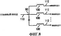
фиг.8 изображает обобщенную схему, имеющую главный вход, который можно разделить на любое число выходов, согласно изобретению;Fig.8 depicts a generalized diagram having a main entrance, which can be divided into any number of outputs according to the invention;
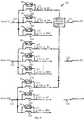
фиг.9 изображает переконфигурируемую систему маршрутизации передачи питания и связи согласно изобретению.Fig. 9 shows a reconfigurable power transmission and communication routing system according to the invention.
Подробное описание предпочтительных вариантов воплощения изобретенияDETAILED DESCRIPTION OF PREFERRED EMBODIMENTS
"Трубопроводная структура", которая используется в настоящей заявке, может представлять собой одну единственную трубу, насосно-компрессорную колонну, обсадную колонну буровой скважины, насосную штангу, ряд взаимосвязанных труб, буровые штанги, направляющие, фермы, решетки сквозной фермы, опоры, отводные или боковые удлинители буровой скважины, сеть взаимосвязанных труб или других подобных структур, известных специалистам. В предпочтительном варианте осуществления изобретения трубопроводная структура содержит трубчатую, металлическую, электропроводную трубу или насосно-компрессорную колонну, но изобретение не ограничено этим. Согласно настоящему изобретению по меньшей мере часть трубопроводной структуры должна быть электропроводной. Такая электропроводная часть может представлять собой трубопроводную структуру (например, стальные трубы, медные трубы) или размещенную в продольном направлении электропроводную часть, объединенную с неэлектропроводной частью. Другими словами, электропроводная трубопроводная структура представляет собой структуру, которая обеспечивает путь тока от первой части, где источник питания электрически связан со второй частью, где устройство и/или цепь обратного тока электрически связаны. Трубопроводная структура представляет собой известную круглую металлическую насосно-компрессорную колонну, но геометрия поперечного сечения трубопроводной структуры или любой ее части может меняться по форме (например, круглая, прямоугольная, квадратная, овальная) и размеру (например, длина, диаметр, толщина стенки) вдоль любой части трубопроводной структуры. Следовательно, трубопроводная структура должна иметь электропроводную часть от первой части трубопроводной структуры до второй части трубопроводной структуры, в которой первая часть расположена отдельно от второй части вдоль трубопроводной структуры.The "pipe structure" used in this application may be one single pipe, tubing, casing of a borehole, pump rod, a series of interconnected pipes, drill rods, guides, trusses, through truss lattices, supports, outlets, or borehole side extensions, a network of interconnected pipes or other similar structures known to those skilled in the art. In a preferred embodiment of the invention, the pipeline structure comprises a tubular, metal, conductive pipe or tubing, but the invention is not limited to this. According to the present invention, at least a portion of the pipe structure must be electrically conductive. Such an electrically conductive part may be a pipe structure (for example, steel pipes, copper pipes) or a longitudinally conductive part, combined with a non-conductive part. In other words, the electrically conductive pipe structure is a structure that provides a current path from a first part where a power source is electrically connected to a second part, where a device and / or a reverse current circuit are electrically connected. The pipeline structure is a known round metal tubing, but the cross-sectional geometry of the pipeline structure or any part thereof can vary in shape (e.g., round, rectangular, square, oval) and size (e.g., length, diameter, wall thickness) along any part of the pipeline structure. Therefore, the pipeline structure must have an electrically conductive part from the first part of the pipeline structure to the second part of the pipeline structure, in which the first part is located separately from the second part along the pipeline structure.
Термины "первая часть" и "вторая часть" обозначают в общем часть, секцию или область трубопроводной структуры, которая может быть расположена в любом выбранном месте вдоль трубопроводной структуры и которая может или не может охватывать наиболее близкие концы трубопроводной структуры.The terms "first part" and "second part" generally refer to a part, section or region of a pipe structure that may be located at any selected location along the pipe structure and which may or may not span the closest ends of the pipe structure.
Термин "модем" используется в описании для любого устройства связи для передачи и/или приема электрических сигналов связи через электрический проводник (например, металл). Следовательно, термин "модем" не ограничен акронимом для модулятора (устройства, которое преобразует голос или сигнал данных к виду, пригодному для передачи)/демодулятора (устройства, которое восстанавливает первоначальный сигнал, которым была промодулирована высокочастотная несущая). Кроме того, термин "модем" не ограничен известными компьютерными модемами, которые преобразовывают цифровые сигналы в аналоговые сигналы и наоборот (например, для передачи цифровых информационных сигналов по аналоговой коммутируемой телефонной сети общего пользования). Если датчик выдает данные измерений в аналоговом формате, то их можно только модулировать (например, с использованием модуляции с расширением спектра) и передавать, и, следовательно, не нужно выполнять аналого-цифрового преобразования. Другим примером является релейный/подчиненный модем или устройство связи, которые должны только идентифицировать, фильтровать, усиливать и/или ретранслировать принимаемый сигнал.The term “modem” is used in the description for any communication device to transmit and / or receive electrical communication signals through an electrical conductor (eg, metal). Therefore, the term “modem” is not limited to the acronym for modulator (a device that converts a voice or data signal to a form suitable for transmission) / demodulator (a device that restores the original signal that modulated a high-frequency carrier). In addition, the term “modem” is not limited to known computer modems that convert digital signals to analog signals and vice versa (for example, to transmit digital information signals over an analogue public switched telephone network). If the sensor provides measurement data in analog format, then they can only be modulated (for example, using spread spectrum modulation) and transmitted, and therefore, there is no need for analog-to-digital conversion. Another example is a relay / slave modem or communication device, which should only identify, filter, amplify and / or relay the received signal.
Термин "клапан" относится к любому устройству, которое выполняет функции регулировки потока флюида. Примеры клапанов включают, но не ограничиваются, сильфонные газлифтные клапаны и управляемые газлифтные клапаны, каждый из которых можно использовать для регулировки потока транспортирующего газа в колонну насосно-компрессорных труб буровой скважины. Внутренняя работа клапанов может в значительной степени отличаться, и в настоящей заявке не ограничиваются клапанами любой конкретной конфигурации, клапан выполняет функции регулировки потока. Некоторые из различных типов механизмов регулировки потока включают шаровой клапан, игольчатый клапан, запорный клапан и клетевой клапан. Способы установки клапанов, обсужденных в настоящей заявке, могут изменяться в широких пределах.The term “valve” refers to any device that performs the function of adjusting fluid flow. Examples of valves include, but are not limited to, bellows gas lift valves and controlled gas lift valves, each of which can be used to control the flow of carrier gas into the tubing string of the borehole. The internal operation of the valves may vary significantly, and in this application are not limited to valves of any particular configuration, the valve performs flow control functions. Some of the various types of flow control mechanisms include ball valve, needle valve, shutoff valve, and cage valve. The valve installation methods discussed in this application can vary widely.
Термин "клапан с электрическим управлением", обычно относится к "клапану" (как описано выше), который можно открывать, закрывать, регулировать, изменять или дросселировать непрерывно в ответ на электрический сигнал управления (например, сигнал из компьютера на поверхности или из скважинного модуля электронного контроллера). Механизм, который фактически изменяет состояние клапана, может содержать электродвигатель, электрический серводвигатель, электрический соленоид, электрический переключатель, гидравлический привод, управляемый по меньшей мере одним электрическим серводвигателем, электродвигателем, электрическим переключателем, электрическим соленоидом или их комбинациями, пневматический привод, управляемый по меньшей мере одним электрическим серводвигателем, электродвигателем, электрическим переключателем, электрическим соленоидом или их комбинациями, или устройство с отклоняемой пружиной в комбинации с по меньшей мере одним электрическим серводвигателем, электродвигателем, электрическим переключателем, электрическим соленоидом или их комбинациями. "Клапан с электрическим управлением" может включать датчик положения с обратной связью для подачи сигнала обратной связи, соответствующего фактическому положению клапана.The term “electrically controlled valve” generally refers to a “valve” (as described above) that can be opened, closed, controlled, changed or throttled continuously in response to an electrical control signal (for example, a signal from a computer on the surface or from a well module electronic controller). The mechanism that actually changes the state of the valve may include an electric motor, an electric servomotor, an electric solenoid, an electric switch, a hydraulic actuator controlled by at least one electric servomotor, an electric motor, an electric switch, an electric solenoid or combinations thereof, a pneumatic actuator controlled by at least one electric servomotor, electric motor, electric switch, electric solenoid, or a combination thereof atsiyami or deflectable spring device in combination with at least one electric servomotor, electric motor, electrical switch, electric solenoid, or combinations thereof. An “electrically controlled valve” may include a feedback position sensor to provide a feedback signal corresponding to the actual position of the valve.
Термин "датчик" относится к любому устройству, которое обнаруживает, определяет, контролирует, записывает или регистрирует абсолютное значение или изменение значения физической величины. Датчик можно использовать для измерения значений таких физических величин как температура, давление (абсолютное и дифференциальное), скорость потока, сейсмические данные, акустические данные, уровень рН, уровни солености, положения клапана или практически любые другие физические данные.The term "sensor" refers to any device that detects, detects, monitors, records or records the absolute value or change in the value of a physical quantity. The sensor can be used to measure values of such physical quantities as temperature, pressure (absolute and differential), flow rate, seismic data, acoustic data, pH level, salinity levels, valve positions or almost any other physical data.
Фраза "на поверхности" относится к местоположению от поверхности Земли на глубину приблизительно пятидесяти и более футов. Другими словами, фраза "на поверхности" не обязательно означает расположение на уровне поверхности земли, а используется в более широком смысле для обозначения местоположения, которое является обычно легкодоступным или удобным в устье скважины, где могут работать люди. Например, "на поверхности" может означать на столе в рабочей мастерской, которая расположена на поверхности земли на платформе буровой скважины, на дне океана или озера, на глубоководной платформе нефтяной вышки или на 100-м этаже здания. Кроме того, термин "поверхность" может использоваться как прилагательное для определения местоположения элемента или области, которая расположена "на поверхности". Например, фраза "поверхностный компьютер" означает компьютер, расположенный "на поверхности".The phrase “on the surface” refers to a location from the surface of the Earth to a depth of approximately fifty or more feet. In other words, the phrase "on the surface" does not necessarily mean a location at ground level, but is used in a broader sense to indicate a location that is usually easily accessible or convenient at the wellhead where people can work. For example, “on the surface” may mean on a table in a workshop that is located on the surface of the earth on a borehole platform, on the bottom of an ocean or lake, on a deep-water platform of an oil rig or on the 100th floor of a building. In addition, the term “surface” can be used as an adjective to determine the location of an element or region that is located “on the surface”. For example, the phrase "surface computer" means a computer located "on the surface."
Термин "скважинный" относится к местоположению на глубине около пятидесяти футов или ниже. Другими словами, термин "скважинный" относится к местоположению, которое обычно трудно или неудобно достигнуть из устья скважины, где могут работать люди. Например, в нефтяной скважине имеется ввиду участок в или рядом с подземной нефтяной эксплуатационной зоной, независимо от того, является ли эксплуатационная зона доступной вертикально, горизонтально, сбоку или под любым другим углом между ними. Кроме того, термин "скважинный" используется как прилагательное, описывающее местоположение элемента или области. Например, "скважинное" устройство в буровой скважине означает, что устройство расположено "в скважине", а не "на поверхности".The term “downhole” refers to a location at a depth of about fifty feet or lower. In other words, the term “downhole” refers to a location that is usually difficult or inconvenient to reach from the wellhead where people can work. For example, in an oil well, this refers to a section in or near an underground oil production zone, regardless of whether the production zone is accessible vertically, horizontally, sideways, or at any other angle between them. In addition, the term “downhole” is used as an adjective describing the location of an element or region. For example, a “borehole” device in a borehole means that the device is located “in the borehole” and not “on the surface”.
Термин "беспроводной" означает отсутствие электрического провода с поверхности к скважинному устройству. Использование трубопроводной структуры буровой скважины (например, насосно-компрессорной колонны и/или обсадной колонны) в качестве проводника рассматривается "беспроводным".The term "wireless" means the absence of an electrical wire from the surface to the downhole device. Using the pipeline structure of a borehole (eg, tubing and / or casing) as a conductor is considered “wireless”.
На фиг.1 изображена схема газлифтной буровой нефтяной эксплуатационной скважины 20, согласно предпочтительному варианту осуществления настоящего изобретения. Буровая скважина 20 имеет главную буровую скважину с боковым ответвлением 26. Буровая скважина 20 может содержать четыре секции - секция 26 бокового ответвления, секция 27 соединения, верхняя секция 28 и нижняя главная секция 29 ствола скважины. Боковое ответвление 26 соединяется с главным стволом скважины в секции 27 соединения. Верхняя секция 28 проходит выше секции 27 на поверхность. Буровая скважина 20 имеет обсадную колонну 30, размещенную внутри ствола скважины и проходящую через геологическую формацию 32 в эксплуатационные зоны (не показаны) дальше в местоположение. Эксплуатационная насосно-компрессорная колонна 40 проходит внутри обсадной колонны буровой скважины и служит для перенаправления флюидов (например, нефти, газа) из скважинного местоположения на поверхность при добыче. Пакеры 42 расположены у обсадной колонны 30 и насосно-компрессорной колонны 40. Пакеры 42 известны и гидравлически изолируют секции 26-29 буровой скважины над эксплуатационными зонами, позволяя вводить газ под давлением в кольцо 44 между обсадной колонной 30 и насосно-компрессорной колонной 40. Во время операции газлифта газ под давлением вводят на поверхности земли в кольцо 44 для дальнейшего ввода в насосно-компрессорную колонну 40, чтобы выполнить газлифт для флюидов, находящихся в ней. Нефтяная эксплуатационная скважина 20 подобна по конструкции известной буровой скважине.Figure 1 shows a diagram of a gas lift
Электрическая цепь образована элементами буровой скважины 20 и используется для подачи питания и/или сигналов связи в скважинные устройства 50. Компьютерная система 52 обеспечивает подачу питания и/или сигналов связи на поверхность. Компьютерная система 52 содержит источник 54 питания и главный модем 56, но элементы поверхностного оборудования и конфигурация могут изменяться. Источник 54 питания предназначен для подачи тока, изменяющегося во времени, который является предпочтительно переменным током, но он может быть также изменяющимся во времени постоянным током. Сигнал связи, подаваемый с помощью компьютерной системы 52, является сигналом с расширенным спектром, но в альтернативном варианте можно использовать и другие виды модуляции или предыскажения. Первый вывод 61 компьютера компьютерной системы 52 электрически связан с насосно-компрессорной колонной 40 на поверхности. Первый вывод 61 компьютера проходит через подвеску 64 в изолированном уплотнении 65 и электрически изолирован от подвески 64 при прохождении через уплотнитель 65. Второй вывод 62 компьютера компьютерной системы 52 электрически связан с обсадной колонной 30 буровой скважины на поверхности.The electrical circuit is formed by elements of the
Насосно-компрессорная колонна 40 и обсадная колонна 30 в схеме буровой скважины выполняют роль электрических проводников. В предпочтительном варианте осуществления (фиг.1) насосно-компрессорная колонна 40 действует как структура для передачи электрической энергии и/или сигналов связи между компьютерной системой 52 на поверхности и скважинным устройством 50. Пакеры 42 и обсадная колонна 30 используются в качестве цепи обратного тока. Изолированная соединительная муфта 68 для насосно-компрессорных труб размещена в устье скважины ниже подвески 64, чтобы обеспечить электрическую изоляцию насосно-компрессорной трубы 40 от подвески 64 и обсадной колонны 30 на поверхности. Первый вывод 61 компьютера электрически связан с насосно-компрессорной колонной 40 ниже изолированной соединительной муфты 68 для насосно-компрессорных труб.The
Индукционные дроссели 70 расположены в скважине около насосно-компрессорной колонны 40. Индукционный дроссель 70 выполнен в форме кольца и расположен концентрически вокруг насосно-компрессорной колонны 40. Каждый индукционный дроссель 70 содержит ферромагнитный материал и не запитан. Каждый индукционный дроссель 70 выполняет функции с учетом своего размера (массы), геометрии и магнитных свойств, а также пространственного расположения относительно насосно-компрессорной трубы 40. В некоторых вариантах осуществления (не показаны) каждый или оба из индукционных дросселей 70 расположены вокруг обсадной колонны 30.Induction chokes 70 are located in the well near the
Каждое скважинное устройство 50 имеет два электрических вывода 71, 72. Первый из выводов 71 электрически связан с насосно-компрессорной колонной 40 на стороне 81 источника соответствующего индукционного дросселя 70. Второй из выводов 72 устройства электрически связан с насосно-компрессорной колонной 40 на стороне 82 цепи обратного тока соответствующего индукционного дросселя 70. Каждый пакер 42 обеспечивает электрическое соединение между насосно-компрессорной трубой 40 и обсадной колонной 30 в скважине. Однако насосно-компрессорная труба 40 и обсадная колонна 30 могут быть также электрически связаны в скважине с помощью проводящего флюида (не показан) в кольце 44 выше пакера 42 или другим образом. Флюид в кольце 44 выше каждого пакера 42 предпочтительно иметь малую или нулевую проводимость, но на практике это нельзя предотвратить.Each
Другие альтернативные способы образования электрической цепи с использованием трубопроводной структуры буровой скважины и по меньшей мере одного индукционного дросселя описаны в родственных заявках. Родственные заявки описывают способы, основанные на использовании обсадной колонны, а не насосно-компрессорной колонны, для передачи питания с поверхности в скважинные устройства.Other alternative methods of forming an electrical circuit using the pipeline structure of the borehole and at least one induction inductor are described in related applications. Related applications describe methods based on the use of a casing string, rather than a tubing string, for transferring surface power to downhole devices.
Предпочтительно, чтобы все элементы скважинного устройства 50 находились в одном герметичном коллекторе насосно-компрессорной колонны в виде одного модуля для облегчения работы и установки, а также защиты элементов от воздействия окружающей среды. Однако в других вариантах осуществления изобретения элементы скважинного устройства 50 могут размещаться отдельно (то есть не в коллекторе насосно-компрессорной колонны) или объединены.Preferably, all the elements of the
Элементы скважинных устройств 50 могут варьироваться для получения других вариантов осуществления изобретения. Например, скважинное устройство 50 может содержать электрический сервопривод, другой электродвигатель, датчик или преобразователь, преобразователи, электрически управляемое устройство нагнетания индикатора, электрически управляемое устройство нагнетания химических реагентов, резервуар для хранения химических реагентов или индикатора, клапан с электрическим управлением, релейный модем, модуль связи и управления, логическую схему, компьютерную систему, память, микропроцессор, силовой трансформатор, модуль или устройство для хранения энергии, электрически управляемый гидравлический насос и/или привод, электрически управляемый пневматический насос и/или привод или любую их комбинацию. Каждое скважинное устройство 50 содержит электрически управляемый газлифтный клапан (не показан) и модуль для хранения энергии (не показан).Elements of
Управляемый индивидуально адресуемый электрический шунтирующий переключатель 90 последовательно электрически связан с цепью первого вывода 71 каждого из устройств 50. Каждым переключателем 90 можно управлять с помощью компьютерной системы 52 с поверхности, скважинного модуля управления переключателем (не показано), другого скважинного устройства 50, соответствующего скважинного устройства 50, схемы управления, расположенной внутри переключателя, или любой их комбинации. Например, каждый алгоритм управления переключением может быть основан на временной последовательности, измеренной с помощью схемы синхронизации и синхронизованной или согласованной с другими переключателями. Переключатели 90 могут быть аналоговыми или цифровыми. Перемещение рабочего органа каждого из переключателей 90 можно осуществлять различными способами, известными специалистам, электрическим, механическим, гидравлическим или пневматическим. Энергия для управления и переключения каждого переключателя 90 может поступать только из накопленной энергии, из аккумуляторного устройства, с поверхности (например, от источника 54 питания) через насосно-компрессорную колонну 40 и/или обсадную колонну 30, из другого скважинного устройства 50 через отдельный провод (не показан), насосно-компрессорную колонну 40 и/или обсадную колонну 30 или любой их комбинации. Каждый переключатель 90 можно независимо размыкать или замыкать желательно с помощью компьютерной системы 52, и каждый переключатель 90 питается от аккумулятора, который периодически подзаряжается с помощью поверхностного источника 54 питания через насосно-компрессорную колонну 40 и/или обсадную колонну 30.A controlled individually addressable
На фиг.2 изображена упрощенная электрическая схема, иллюстрирующая электрическую цепь в буровой скважине 20. В процессе работы питание и/или сигналы связи подают с помощью компьютерной системы 52 в насосно-компрессорную колонну 40, расположенную у поверхности ниже изоляционной соединительной муфты 68 для насосно-компрессорных труб, через первый вывод 61 компьютера. Протеканию тока, изменяющегося во времени, из насосно-компрессорной колонны 40 в обсадную колонну 30 (и на второй вывод 62 компьютера) через подвеску 64 препятствуют изоляторы 69 в изоляционной соединительной муфте 68 для насосно-компрессорных труб. Однако ток, изменяющийся во времени, протекает свободно в скважине вдоль насосно-компрессорной колонны 40 до встречи с индукционным дросселем 70. Каждый индукционный дроссель 70 имеет большую индуктивность, которая препятствует протеканию большей части тока через насосно-компрессорную колонну 40 в каждом индукционном дросселе 70. Следовательно, между насосно-компрессорной колонной 40 и обсадной колонной 30 возникает разность потенциалов благодаря индукционным дросселям 70. Так как скважинные устройства 50 электрически связаны перпендикулярно потенциалам напряжения, которые возникают благодаря дросселям 70, большая часть тока, подаваемого в насосно-компрессорную колонну 40 и не потерявшаяся по пути, направляется через скважинные устройства 50 и таким образом обеспечивает подачу питания и/или связь со скважинными устройствами 50. Шунтирующие переключатели 90 определяют, на какое из скважинных устройств 50 поступает питание и/или сигналы связи, поданные с поверхности. Если переключатель 90 нижней главной секции 29 буровой скважины замкнут и переключатель 90 боковой секции 26 разомкнут, то устройство 50 боковой секции 26 не включено в электрический контур, и большая часть тока будет направляться через устройство 50 нижней главной секции 29 буровой скважины. Если переключатель 90 нижней главной секции 29 буровой скважины разомкнут, а переключатель 90 боковой секции 26 замкнут, то устройство 50 нижней главной секции 29 буровой скважины не включено в электрический контур, и большая часть тока будет направляться через устройство 50 боковой секции 26. И если оба переключателя 90 замкнуты, то скважинные устройства 50 будут расположены параллельно, и ток будет проходить через них. После прохождения тока через один или оба скважинных устройства 50 ток возвращается обратно в компьютерную систему 52 через пакер(ы) 42, обсадную колонну 30 и второй вывод 62 компьютера. Когда ток является переменным током, направление протекания этого тока через буровую скважину 20 будет меняться на противоположное и проходить по тому же пути.FIG. 2 is a simplified circuit diagram illustrating an electrical circuit in a
Если другие пакеры или центраторы (не показаны) введены между изоляционной соединительной муфтой 68 для насосно-компрессорных труб и пакером 42, то их можно ввести в состав электрического изолятора, чтобы предотвратить короткое замыкание между насосно-компрессорной колонной 40 и обсадной колонной 30. Подходящие центраторы могут состоять из цельно формованной или механически обработанной пластмассы или представлять собой тип рессоры, снабженной, при необходимости, соответствующими изолирующими элементами. Электрическую изоляцию дополнительных пакеров или центраторов можно осуществить другими способами, очевидными для специалистов.If other packers or centralizers (not shown) are inserted between the tubing insulator 68 and the
Альтернативой (или дополнением) для изоляционной соединительной муфты 68 для насосно-компрессорных труб может служить другой индукционный дроссель 168 (фиг.3А), который можно разместить около насосно-компрессорной колонны 40 выше электрического соединения для первого вывода 61 компьютера в насосно-компрессорной трубе 40, и/или подвеска 64, в качестве которой может быть использована изолированная подвеска 268 (фиг.3В), имеющая изоляторы 269 для электрической изоляции насосно-компрессорной трубы 40 от обсадной колонны 30. Таким образом, верхнюю часть буровой скважины можно изменять для формирования других возможных вариантов воплощения.An alternative (or addition) to the insulating coupling 68 for tubing can be another induction choke 168 (FIG. 3A), which can be placed near the
Конфигурации переключателей и их расположение можно изменять. Например, в буровую скважину 20 (фиг.1) можно добавить секцию 27 соединения, нижнюю главную секцию 29 ствола буровой скважины и боковую секцию 26 ответвления (фиг.4). На фиг.4 переключатели 90 с соответствующими индукционными дросселями 100 расположены в секции 27 соединения, и скважинные устройства 50 с соответствующими индукционными дросселями 70 расположены дальше в скважине внутри нижней главной секции 29 ствола буровой скважины и боковой секции 26. На фиг.5 изображена упрощенная электрическая схема, иллюстрирующая электрическую цепь, образованную в случае, когда в буровую скважину 20 (фиг.1) добавлены секции 26, 27 и 29 (фиг.4).The configurations of the switches and their location can be changed. For example, in the borehole 20 (FIG. 1), a
В другом примере в буровую скважину 20 (фиг.1 и/или 4) добавляют секцию 27 соединения (фиг.6). На фиг.6 показан один переключатель 90 для направления питания и/или связи в нижнюю главную секцию 29 буровой скважины или в боковую секцию 26, но не в обе. В альтернативном варианте секция 27 соединения (фиг.6) может содержать два переключателя в одном корпусе (не показано) или переключатель на три направления (не показано), причем любой вариант адаптирован для подачи питания и/или осуществления связи в нижнюю главную секцию 29 буровой скважины и/или в боковую секцию 26. На фиг.7 изображена упрощенная электрическая схема электрической цепи для случая, когда секция 27 соединения (фиг.6) введена в буровую скважину 20 (фиг.1) с нижней главной секцией 29 буровой скважины и боковой секцией 26 (фиг.4).In another example, a connection section 27 (FIG. 6) is added to the borehole 20 (FIG. 1 and / or 4). 6 shows one
На фиг.8 изображена схема, иллюстрирующая обобщенную конфигурацию, где имеется главный входной сигнал 110 (например, из компьютерной системы 52), который можно разделить на любое число (Y) выходов 112. Конфигурация переключателя может учитывать только один выход в данный момент времени (фиг.6) или любую комбинацию выходов в данный момент времени (фиг.4). Таким образом, один главный вход 110 можно разделить на Y выходов 112. Но с другой стороны, можно также использовать любое число Х главных входов 110.8 is a diagram illustrating a generalized configuration where there is a main input signal 110 (for example, from a computer system 52), which can be divided into any number (Y) of
На фиг.9 изображена другая схема, показывающая как можно выполнить переконфигурируемую систему 120 маршрутизации передачи питания и связи для электрической цепи буровой скважины, образованной трубопроводной структурой буровой скважины. Система 120 содержит индивидуально управляемые переключатели 90 и позволяет обеспечить соединение каждой из N входных "линий" 122 с любой одной или более М выходными "линиями" 124, где "линии" - это части трубопроводной структуры буровой скважины (например, эксплуатационной насосно-компрессорной колонны 40 и/или обсадной колонны 30).Fig. 9 is another diagram illustrating how a reconfigurable power transmission and
В области телекоммуникации аналогичная система для телефонных линий часто называется "координатным коммутатором". Типичный электрический коммутатор представляет собой матрицу из пересекающихся проводников входных "строк" и выходных "столбцов" с механическими или транзисторными переключателями, размещенными в каждом узле ортогональных строк и столбцов. Переключатель в любом конкретном узле можно уникальным способом адресовать и возбудить для того, чтобы завершить соединение между пересекающимися входными линиями и выходными линиями. При возбуждении одного и только одного переключателя вдоль одной входной линии "строка" достигают уникального соединения с выходной "колонкой". Замкнутую цепь можно использовать для передачи электрической энергии или электрических сигналов из источника, подсоединенного к "входной" линии, в место назначения, подсоединенное к "выходной" линии. В телефонии матричные переключатели используются для маршрутизации вызовов между заданным местоположением источника и конкретным местоположением приемника.In the field of telecommunications, a similar system for telephone lines is often referred to as a "coordinate switch." A typical electrical switch is a matrix of intersecting conductors of input “rows” and output “columns” with mechanical or transistor switches located at each node of orthogonal rows and columns. A switch in any particular node can be uniquely addressed and energized in order to complete the connection between intersecting input lines and output lines. When one and only one switch is energized along one input line, the “line” achieves a unique connection to the output “column”. A closed circuit can be used to transfer electrical energy or electrical signals from a source connected to an “input” line to a destination connected to an “output” line. In telephony, matrix switches are used to route calls between a given source location and a specific receiver location.
Электрическая схема (фиг.9) изображает сеть пересекающихся колонн насосно-компрессорных труб и/или секций обсадной колонны буровой скважины (сеть, образованную трубопроводами буровой скважины), имеющая N входных линий 122 и М выходных линий 124. Предполагается, что каждая из N входных линий 122 подсоединена к каждой из М выходных линий 124 с помощью индукционного дросселя 100 и одного или более шунтирующих переключателей 90, размещенных в каждом узле 127. Например, в каждом узле 127 можно использовать независимо адресуемый электронный или механический коммутационный мост (не показан). Схема контроллера (не показана) может обеспечить полное соединение для подачи питания и/или осуществления связи путем активизации электронных или механических переключателей 90 и "замыкания накоротко" или шунтирования соответствующих индукционных дросселей 100. Переключатели 90 можно настроить таким образом, чтобы они были нормально разомкнуты или нормально замкнутыми в "неактивном" состоянии. То есть нормальным невозбужденным состоянием каждого переключателя 90 может быть состояние "выключено" (разомкнуто) или состояние "включено" (замкнуто). В предпочтительном варианте осуществления изобретения предполагается, что все переключатели разомкнуты. Со всеми узловыми переключателями 90 в естественном открытом положении дроссели 100, установленные около линий узлов 127, блокируют некоторую часть, большую часть или всю передачу питания и/или связи в выходные линии 124 до тех пор, пока переключатель 90 не будет активизирован для конкретного узла 127.The electrical circuit (Fig. 9) depicts a network of intersecting tubing strings and / or borehole casing sections (a network formed by borehole pipelines) having
Например, если переменный ток подается во входную линию А1 на фиг.9, то индукционный дроссель 100 препятствует прохождению электрического тока в выходные линии В1-ВМ. Однако, если электрический сигнал проходит в схему управления шунтированием, расположенную параллельно узлу "А1 в В2" дросселя, то соответствующий электронный переключатель 90 замыкается, и соответствующий дроссель 100 шунтируется. Следовательно, переменный ток и незапрещенные сигналы связи могут проходить из входной линии А1 в выходную линию В2. Дополнительный электрический сигнал управления может проходить в схему управления шунтированием, расположенную параллельно узлу "А2 в В7" дросселя (не показана), управляя соответствующим переключателем 90 для размыкания и завершения дополнительного электрического соединения между входной линией А2 и выходной линией В7. Таким образом, одним из возможных приложений настоящего изобретения является формирование связи от точки к точке и/или связи между рядом входных линий 122 и рядом выходных линий 124 в сети, образованной трубопроводами буровой скважины.For example, if alternating current is supplied to the input line A1 in FIG. 9, then the
В другом примере, если питание по переменному току подается на входные линии A1-AN (фиг.9), то на начальном этапе индукционные дроссели 100 препятствуют прохождению электрического тока в выходные линии В1-ВМ. Но если электрические сигналы управления поступают в схему управления шунтированием, расположенную в каждом узле дросселя для В1 (то есть А1 в B1, A2 в В1,...AN в В1), то соответствующие переключатели 90 будут замыкаться, и соответствующие дроссели 100 будут шунтироваться. Следовательно, все входы A1-AN будут объединяться в выход B1. Поэтому с помощью настоящего изобретения можно выполнить полностью переконфигурируемую систему 120 сети матричных переключателей путем установки дросселей 100 общим количеством M*N и переключателей 90 в узлах 127 между N входных линий 122 и М выходных линий 124.In another example, if AC power is supplied to the input lines A1-AN (Fig. 9), then at the initial stage, induction chokes 100 prevent the passage of electric current to the output lines B1-VM. But if the electrical control signals are supplied to the bypass control circuit located at each throttle assembly for B1 (i.e., A1 to B1, A2 to B1, ... AN to B1), then the corresponding switches 90 will close and the corresponding
В случае, когда желательно иметь частичную передачу питания и/или связи в сетке 120 "М на N" (фиг.9) для одного или более узлов 127 или для всех узлов 127, можно установить меньшие дроссели там, где желательно, чтобы питание и/или связь полностью не терялись в узлах 127, имеющих меньшие дроссели. Меньший дроссель может быть физически меньше (то есть иметь меньшую массу относительно других дросселей 100) и/или может иметь различные магнитные свойства (то есть содержать меньше ферромагнитного материала). Другими словами, меньший дроссель - это дроссель, который обеспечивает меньшее эффективное полное сопротивление для переменного тока, протекающего через трубопроводы буровой скважины. Следовательно, ограниченное (то есть, уменьшенное) количество энергии можно подать в оборудование, подсоединенное к конкретной выходной линии 124, для контроля, например, в случае регулирующего клапана интервала, когда соответствующий шунтирующий переключатель 90 дросселя находится в разомкнутом или "выключенном" положении. Если полное питание необходимо направить в оборудование, подсоединенное к данной выходной линии 124 для других целей, например, чтобы открыть регулирующий клапан интервала, то соответствующий шунтирующий переключатель 90 дросселя можно замкнуть или "включить". Поэтому в настоящем изобретении выполнен способ и устройство для переключения и направления напряжения питания и/или связи по сети колонн 40 насосно-компрессорных труб и/или секций обсадной колонны 30, т.е. трубопроводных структур буровой скважины.In the case where it is desirable to have a partial transmission of power and / or communication in the
Настоящее изобретение можно применять к любому типу скважин, например скважин для разведочных работ, нагнетательных скважин, эксплуатационных скважин, где питание в скважине необходимо для электронного или электрического оборудования. Настоящее изобретение можно также применять к другим типам скважин, например, водозаборным скважинам.The present invention can be applied to any type of well, such as exploratory wells, injection wells, production wells, where power in the well is necessary for electronic or electrical equipment. The present invention can also be applied to other types of wells, for example, water wells.
Систему можно использовать много раз в одной нефтяной скважине, имеющей одну или более продуктивных зон или в нефтяной скважине, имеющей многочисленные боковые или горизонтальные ответвления. Так как конфигурация буровой скважины зависит от расположения природной геологической формации и местоположения продуктивных зон, система согласно изобретению может изменяться в зависимости от геологической формации или требований, предъявляемых к подаче напряжения и/или установке связи в буровой скважине.The system can be used many times in a single oil well having one or more productive zones or in an oil well having multiple lateral or horizontal branches. Since the configuration of the borehole depends on the location of the natural geological formation and the location of the productive zones, the system according to the invention may vary depending on the geological formation or the requirements for voltage supply and / or communication in the borehole.
Настоящее изобретение можно также применять и в других областях, где трубопроводная структура используется для образования электрической цепи в качестве электрических проводников и индукционного дросселя. Кроме того, настоящее изобретение можно использовать там, где структурные элементы системы или элементы передачи флюида используются для образования электрической цепи внутри системы с помощью индукционных дросселей. Например, настоящее изобретение можно использовать для управляемой подачи питания и/или связи через существующую сеть труб спринклерной системы в здании, существующую сеть металлических структурных элементов в здании, существующую сеть металлических структурных элементов для нефтяной платформы, существующую трубопроводную сеть, например водопроводную сеть, существующую сеть структурных элементов фермы моста и существующую сеть металлических арматурных стержней железобетона, например в дороге или дамбе.The present invention can also be applied in other fields where a pipe structure is used to form an electric circuit as electrical conductors and an induction inductor. In addition, the present invention can be used where structural elements of the system or fluid transfer elements are used to form an electrical circuit within the system using induction chokes. For example, the present invention can be used for controlled power supply and / or communication through an existing pipe network of a sprinkler system in a building, an existing network of metal structural elements in a building, an existing network of metal structural elements for an oil platform, an existing pipeline network, for example, a water supply network, an existing network structural elements of the bridge truss and the existing network of reinforced concrete metal reinforcing bars, for example, on the road or dam.
Claims (38)
Translated fromRussianApplications Claiming Priority (2)
| Application Number | Priority Date | Filing Date | Title |
|---|---|---|---|
| US18637800P | 2000-03-02 | 2000-03-02 | |
| US60/186,378 | 2000-03-02 |
Publications (2)
| Publication Number | Publication Date |
|---|---|
| RU2002126212A RU2002126212A (en) | 2004-02-27 |
| RU2256074C2true RU2256074C2 (en) | 2005-07-10 |
Family
ID=22684710
Family Applications (1)
| Application Number | Title | Priority Date | Filing Date |
|---|---|---|---|
| RU2002126212/03ARU2256074C2 (en) | 2000-03-02 | 2001-03-02 | System for controlling connections and feeding of electric current, oil well for extracting oil products (variants) and method for extracting oil product from oil well |
Country Status (11)
| Country | Link |
|---|---|
| US (1) | US6868040B2 (en) |
| EP (1) | EP1259708B1 (en) |
| AU (2) | AU2001245389B2 (en) |
| BR (1) | BR0108886A (en) |
| CA (1) | CA2401791C (en) |
| DE (1) | DE60123759T2 (en) |
| MX (1) | MXPA02008576A (en) |
| NO (1) | NO323531B1 (en) |
| OA (1) | OA12223A (en) |
| RU (1) | RU2256074C2 (en) |
| WO (1) | WO2001065718A2 (en) |
Cited By (5)
| Publication number | Priority date | Publication date | Assignee | Title |
|---|---|---|---|---|
| RU2470144C1 (en)* | 2011-05-31 | 2012-12-20 | Иван Викторович Грехов | Plant for simultaneous-separate extraction of hydrocarbons |
| RU2494250C1 (en)* | 2012-01-19 | 2013-09-27 | Общество с ограниченной ответственностью Научно-производственная фирма "ГОРИЗОНТ" (ООО НПФ "ГОРИЗОНТ") | Method for information transmission via electromagnetic communication channel at operation of well, and device for its implementation |
| US8763725B2 (en) | 2007-06-26 | 2014-07-01 | Schlumberger Technology Corporation | Rotary steerable drilling system |
| RU2522825C1 (en)* | 2010-06-21 | 2014-07-20 | Халлибертон Энерджи Сервисез, Инк. | System and method of isolation of current supplied to electric load in well |
| RU2696954C1 (en)* | 2018-04-02 | 2019-08-07 | Государственное бюджетное образовательное учреждение высшего образования "Альметьевский государственный нефтяной институт" | Device for transmitting information over an electromagnetic communication channel during operation of wells |
Families Citing this family (34)
| Publication number | Priority date | Publication date | Assignee | Title |
|---|---|---|---|---|
| US7259688B2 (en) | 2000-01-24 | 2007-08-21 | Shell Oil Company | Wireless reservoir production control |
| US7322410B2 (en) | 2001-03-02 | 2008-01-29 | Shell Oil Company | Controllable production well packer |
| US7668700B2 (en)* | 2001-09-29 | 2010-02-23 | The Boeing Company | Adaptive distance field constraint for designing a route for a transport element |
| US7444269B2 (en)* | 2001-09-29 | 2008-10-28 | The Boeing Company | Constraint-based method of designing a route for a transport element |
| WO2003031686A2 (en)* | 2001-10-12 | 2003-04-17 | Envirosense, Llc | Cathodic protection remote monitoring method and apparatus |
| US8284075B2 (en)* | 2003-06-13 | 2012-10-09 | Baker Hughes Incorporated | Apparatus and methods for self-powered communication and sensor network |
| US20060028916A1 (en)* | 2004-08-06 | 2006-02-09 | Mcmechan David | Acoustic telemetry installation in subterranean wells |
| US7436184B2 (en) | 2005-03-15 | 2008-10-14 | Pathfinder Energy Services, Inc. | Well logging apparatus for obtaining azimuthally sensitive formation resistivity measurements |
| US7414405B2 (en) | 2005-08-02 | 2008-08-19 | Pathfinder Energy Services, Inc. | Measurement tool for obtaining tool face on a rotating drill collar |
| US7606592B2 (en)* | 2005-09-19 | 2009-10-20 | Becker Charles D | Waveguide-based wireless distribution system and method of operation |
| US7649474B1 (en) | 2005-11-16 | 2010-01-19 | The Charles Machine Works, Inc. | System for wireless communication along a drill string |
| US7558675B2 (en) | 2007-07-25 | 2009-07-07 | Smith International, Inc. | Probablistic imaging with azimuthally sensitive MWD/LWD sensors |
| GB0804306D0 (en) | 2008-03-07 | 2008-04-16 | Petrowell Ltd | Device |
| ATE534924T1 (en)* | 2008-06-18 | 2011-12-15 | Expro North Sea Ltd | GENERATION OF ELECTRICAL IMPEDANCE IN A CONVEYOR LINE |
| GB2461064A (en)* | 2008-06-18 | 2009-12-23 | Expro North Sea Ltd | Flow line electric impedance generation |
| EP2157278A1 (en)* | 2008-08-22 | 2010-02-24 | Schlumberger Holdings Limited | Wireless telemetry systems for downhole tools |
| US8330617B2 (en)* | 2009-01-16 | 2012-12-11 | Schlumberger Technology Corporation | Wireless power and telemetry transmission between connections of well completions |
| US8600115B2 (en) | 2010-06-10 | 2013-12-03 | Schlumberger Technology Corporation | Borehole image reconstruction using inversion and tool spatial sensitivity functions |
| US9658360B2 (en) | 2010-12-03 | 2017-05-23 | Schlumberger Technology Corporation | High resolution LWD imaging |
| GB2500849B (en)* | 2011-02-11 | 2019-02-13 | Statoil Petroleum As | Signal and power transmission in hydrocarbon wells |
| RU2469181C1 (en)* | 2011-05-16 | 2012-12-10 | Общество с ограниченной ответственностью "ЛУКОЙЛ-Западная Сибирь" | Pump unit for simultaneous separate operation of two formations in well |
| AU2012367826A1 (en) | 2012-01-23 | 2014-08-28 | Genie Ip B.V. | Heater pattern for in situ thermal processing of a subsurface hydrocarbon containing formation |
| US10047594B2 (en) | 2012-01-23 | 2018-08-14 | Genie Ip B.V. | Heater pattern for in situ thermal processing of a subsurface hydrocarbon containing formation |
| US9670739B2 (en) | 2012-11-29 | 2017-06-06 | Chevron U.S.A. Inc. | Transmitting power to gas lift valve assemblies in a wellbore |
| US20160003027A1 (en)* | 2013-03-12 | 2016-01-07 | Chevron U.S.A. Inc. | System and method for detecting structural integrity of a well casing |
| US9267334B2 (en)* | 2014-05-22 | 2016-02-23 | Chevron U.S.A. Inc. | Isolator sub |
| US10760413B2 (en)* | 2014-12-31 | 2020-09-01 | Halliburton Energy Services, Inc. | Electromagnetic telemetry for sensor systems deployed in a borehole environment |
| WO2016149811A1 (en)* | 2015-03-20 | 2016-09-29 | Cenovus Energy Inc. | Hydrocarbon production apparatus |
| WO2016175827A1 (en) | 2015-04-30 | 2016-11-03 | Halliburton Energy Services, Inc. | Casing-based intelligent completion assembly |
| US10487629B2 (en) | 2015-04-30 | 2019-11-26 | Halliburton Energy Services, Inc. | Remotely-powered casing-based intelligent completion assembly |
| US11982132B2 (en)* | 2019-06-25 | 2024-05-14 | Schlumberger Technology Corporation | Multi-stage wireless completions |
| EP3901407B1 (en)* | 2020-04-24 | 2023-06-07 | Metrol Technology Ltd | Well installations and subsurface safety valves |
| US20250020056A1 (en)* | 2022-11-18 | 2025-01-16 | Tri-Logic Limited Liability Company | Wireless system for monitoring downhole parameters |
| US12392221B2 (en)* | 2023-01-31 | 2025-08-19 | Saudi Arabian Oil Company | Controlling fluid flows in a multi-wellbore well system with a surface controlled formation isolation valve |
Citations (7)
| Publication number | Priority date | Publication date | Assignee | Title |
|---|---|---|---|---|
| SU1247521A1 (en)* | 1985-01-07 | 1986-07-30 | Всесоюзный научно-исследовательский и проектно-конструкторский институт геофизических исследований геологоразведочных скважин | Telemetry system for formation testing |
| US4839644A (en)* | 1987-06-10 | 1989-06-13 | Schlumberger Technology Corp. | System and method for communicating signals in a cased borehole having tubing |
| US5130706A (en)* | 1991-04-22 | 1992-07-14 | Scientific Drilling International | Direct switching modulation for electromagnetic borehole telemetry |
| US5531270A (en)* | 1995-05-04 | 1996-07-02 | Atlantic Richfield Company | Downhole flow control in multiple wells |
| US5745047A (en)* | 1995-01-03 | 1998-04-28 | Shell Oil Company | Downhole electricity transmission system |
| RU2130112C1 (en)* | 1994-02-18 | 1999-05-10 | Шелл Интернэшнл Рисерч Маатсххаппий Б.В. | System for introduction of delivered flowing medium into stream of hydrocarbon fluid |
| US5995020A (en)* | 1995-10-17 | 1999-11-30 | Pes, Inc. | Downhole power and communication system |
Family Cites Families (116)
| Publication number | Priority date | Publication date | Assignee | Title |
|---|---|---|---|---|
| US525663A (en) | 1894-09-04 | Sash-fastener | ||
| US2917004A (en) | 1954-04-30 | 1959-12-15 | Guiberson Corp | Method and apparatus for gas lifting fluid from plural zones of production in a well |
| US3083771A (en) | 1959-05-18 | 1963-04-02 | Jersey Prod Res Co | Single tubing string dual installation |
| US3247904A (en) | 1963-04-01 | 1966-04-26 | Richfield Oil Corp | Dual completion tool |
| US3427989A (en) | 1966-12-01 | 1969-02-18 | Otis Eng Corp | Well tools |
| US3602305A (en) | 1969-12-31 | 1971-08-31 | Schlumberger Technology Corp | Retrievable well packer |
| US3566963A (en) | 1970-02-25 | 1971-03-02 | Mid South Pump And Supply Co I | Well packer |
| US3732728A (en) | 1971-01-04 | 1973-05-15 | Fitzpatrick D | Bottom hole pressure and temperature indicator |
| US3793632A (en) | 1971-03-31 | 1974-02-19 | W Still | Telemetry system for drill bore holes |
| US3814545A (en) | 1973-01-19 | 1974-06-04 | W Waters | Hydrogas lift system |
| US3837618A (en) | 1973-04-26 | 1974-09-24 | Co Des Freins Et Signaux Westi | Electro-pneumatic valve |
| US3980826A (en) | 1973-09-12 | 1976-09-14 | International Business Machines Corporation | Means of predistorting digital signals |
| CA1062336A (en) | 1974-07-01 | 1979-09-11 | Robert K. Cross | Electromagnetic lithosphere telemetry system |
| US4068717A (en) | 1976-01-05 | 1978-01-17 | Phillips Petroleum Company | Producing heavy oil from tar sands |
| US4295795A (en) | 1978-03-23 | 1981-10-20 | Texaco Inc. | Method for forming remotely actuated gas lift systems and balanced valve systems made thereby |
| GB2055131B (en) | 1978-09-29 | 1982-12-15 | Energy Secretary Of State For | Electrical power transmission in fluid wells |
| DE2943979C2 (en) | 1979-10-31 | 1986-02-27 | Licentia Patent-Verwaltungs-Gmbh, 6000 Frankfurt | Arrangement for the transmission of measured values from several measuring points connected in series along an elongated underwater structure to a central station |
| US4393485A (en) | 1980-05-02 | 1983-07-12 | Baker International Corporation | Apparatus for compiling and monitoring subterranean well-test data |
| GB2083321A (en) | 1980-09-03 | 1982-03-17 | Marconi Co Ltd | A method of signalling along drill shafts |
| US4468665A (en) | 1981-01-30 | 1984-08-28 | Tele-Drill, Inc. | Downhole digital power amplifier for a measurements-while-drilling telemetry system |
| US4739325A (en) | 1982-09-30 | 1988-04-19 | Macleod Laboratories, Inc. | Apparatus and method for down-hole EM telemetry while drilling |
| US4578675A (en) | 1982-09-30 | 1986-03-25 | Macleod Laboratories, Inc. | Apparatus and method for logging wells while drilling |
| US4630243A (en) | 1983-03-21 | 1986-12-16 | Macleod Laboratories, Inc. | Apparatus and method for logging wells while drilling |
| CA1212312A (en) | 1983-07-14 | 1986-10-07 | Econolift Systems Ltd. | Electronically controlled gas lift apparatus |
| US4648471A (en) | 1983-11-02 | 1987-03-10 | Schlumberger Technology Corporation | Control system for borehole tools |
| US4545731A (en) | 1984-02-03 | 1985-10-08 | Otis Engineering Corporation | Method and apparatus for producing a well |
| US4576231A (en) | 1984-09-13 | 1986-03-18 | Texaco Inc. | Method and apparatus for combating encroachment by in situ treated formations |
| US4709234A (en) | 1985-05-06 | 1987-11-24 | Halliburton Company | Power-conserving self-contained downhole gauge system |
| US4662437A (en) | 1985-11-14 | 1987-05-05 | Atlantic Richfield Company | Electrically stimulated well production system with flexible tubing conductor |
| US4681164A (en) | 1986-05-30 | 1987-07-21 | Stacks Ronald R | Method of treating wells with aqueous foam |
| US4738313A (en) | 1987-02-20 | 1988-04-19 | Delta-X Corporation | Gas lift optimization |
| US4901069A (en) | 1987-07-16 | 1990-02-13 | Schlumberger Technology Corporation | Apparatus for electromagnetically coupling power and data signals between a first unit and a second unit and in particular between well bore apparatus and the surface |
| US4886114A (en) | 1988-03-18 | 1989-12-12 | Otis Engineering Corporation | Electric surface controlled subsurface valve system |
| US4981173A (en) | 1988-03-18 | 1991-01-01 | Otis Engineering Corporation | Electric surface controlled subsurface valve system |
| US4864293A (en) | 1988-04-29 | 1989-09-05 | Flowmole Corporation | Inground boring technique including real time transducer |
| US4972704A (en) | 1989-03-14 | 1990-11-27 | Shell Oil Company | Method for troubleshooting gas-lift wells |
| US5001675A (en) | 1989-09-13 | 1991-03-19 | Teleco Oilfield Services Inc. | Phase and amplitude calibration system for electromagnetic propagation based earth formation evaluation instruments |
| US5172717A (en) | 1989-12-27 | 1992-12-22 | Otis Engineering Corporation | Well control system |
| US5176164A (en) | 1989-12-27 | 1993-01-05 | Otis Engineering Corporation | Flow control valve system |
| US5008664A (en) | 1990-01-23 | 1991-04-16 | Quantum Solutions, Inc. | Apparatus for inductively coupling signals between a downhole sensor and the surface |
| US5278758A (en) | 1990-04-17 | 1994-01-11 | Baker Hughes Incorporated | Method and apparatus for nuclear logging using lithium detector assemblies and gamma ray stripping means |
| JPH04111127A (en)* | 1990-08-31 | 1992-04-13 | Toshiba Corp | Arithmetic processor |
| GB9025230D0 (en) | 1990-11-20 | 1991-01-02 | Framo Dev Ltd | Well completion system |
| US5251328A (en) | 1990-12-20 | 1993-10-05 | At&T Bell Laboratories | Predistortion technique for communications systems |
| US5134285A (en) | 1991-01-15 | 1992-07-28 | Teleco Oilfield Services Inc. | Formation density logging mwd apparatus |
| GB2253908B (en) | 1991-03-21 | 1995-04-05 | Halliburton Logging Services | Apparatus for electrically investigating a medium |
| US5160925C1 (en) | 1991-04-17 | 2001-03-06 | Halliburton Co | Short hop communication link for downhole mwd system |
| US5574374A (en) | 1991-04-29 | 1996-11-12 | Baker Hughes Incorporated | Method and apparatus for interrogating a borehole and surrounding formation utilizing digitally controlled oscillators |
| AT397833B (en) | 1991-06-03 | 1994-07-25 | Universale Grundbau | DATA TRANSFER METHOD FOR DIGGING AND EARTH DRILLING DEVICES AND FOR HOLE DRILLING DEVICES |
| US5283768A (en) | 1991-06-14 | 1994-02-01 | Baker Hughes Incorporated | Borehole liquid acoustic wave transducer |
| US5493288A (en) | 1991-06-28 | 1996-02-20 | Elf Aquitaine Production | System for multidirectional information transmission between at least two units of a drilling assembly |
| US5191326A (en) | 1991-09-05 | 1993-03-02 | Schlumberger Technology Corporation | Communications protocol for digital telemetry system |
| FR2681461B1 (en) | 1991-09-12 | 1993-11-19 | Geoservices | METHOD AND ARRANGEMENT FOR THE TRANSMISSION OF INFORMATION, PARAMETERS AND DATA TO AN ELECTRO-MAGNETIC RECEIVING OR CONTROL MEMBER ASSOCIATED WITH A LONG LENGTH SUBTERRANEAN PIPING. |
| US5236047A (en) | 1991-10-07 | 1993-08-17 | Camco International Inc. | Electrically operated well completion apparatus and method |
| US5246860A (en) | 1992-01-31 | 1993-09-21 | Union Oil Company Of California | Tracer chemicals for use in monitoring subterranean fluids |
| US5267469A (en) | 1992-03-30 | 1993-12-07 | Lagoven, S.A. | Method and apparatus for testing the physical integrity of production tubing and production casing in gas-lift wells systems |
| GB9212685D0 (en) | 1992-06-15 | 1992-07-29 | Flight Refueling Ltd | Data transfer |
| FR2695450B1 (en) | 1992-09-07 | 1994-12-16 | Geo Res | Safety valve control and command cartridge. |
| FR2697119B1 (en) | 1992-10-16 | 1995-01-20 | Schlumberger Services Petrol | Transmitter device with double insulating connection, intended for use in drilling. |
| EP0737322A4 (en) | 1993-06-04 | 1997-03-19 | Gas Res Inst Inc | METHOD AND DEVICE FOR SIGNAL COMMUNICATION OF OIL-DRILLED HOLES |
| US5353627A (en) | 1993-08-19 | 1994-10-11 | Texaco Inc. | Passive acoustic detection of flow regime in a multi-phase fluid flow |
| US5467083A (en) | 1993-08-26 | 1995-11-14 | Electric Power Research Institute | Wireless downhole electromagnetic data transmission system and method |
| DE4329729A1 (en) | 1993-09-03 | 1995-03-09 | Ieg Ind Engineering Gmbh | Method and device for taking gas or liquid samples from different layers |
| US5425424A (en) | 1994-02-28 | 1995-06-20 | Baker Hughes Incorporated | Casing valve |
| US5473321A (en) | 1994-03-15 | 1995-12-05 | Halliburton Company | Method and apparatus to train telemetry system for optimal communications with downhole equipment |
| US5517464A (en) | 1994-05-04 | 1996-05-14 | Schlumberger Technology Corporation | Integrated modulator and turbine-generator for a measurement while drilling tool |
| NO941992D0 (en) | 1994-05-30 | 1994-05-30 | Norsk Hydro As | Injector for injecting tracer into an oil and / or gas reservoir |
| US5458200A (en) | 1994-06-22 | 1995-10-17 | Atlantic Richfield Company | System for monitoring gas lift wells |
| US5555945A (en) | 1994-08-15 | 1996-09-17 | Halliburton Company | Early evaluation by fall-off testing |
| US5896924A (en) | 1997-03-06 | 1999-04-27 | Baker Hughes Incorporated | Computer controlled gas lift system |
| US6012015A (en) | 1995-02-09 | 2000-01-04 | Baker Hughes Incorporated | Control model for production wells |
| US5887657A (en) | 1995-02-09 | 1999-03-30 | Baker Hughes Incorporated | Pressure test method for permanent downhole wells and apparatus therefore |
| US5732776A (en) | 1995-02-09 | 1998-03-31 | Baker Hughes Incorporated | Downhole production well control system and method |
| US5730219A (en) | 1995-02-09 | 1998-03-24 | Baker Hughes Incorporated | Production wells having permanent downhole formation evaluation sensors |
| US5706896A (en) | 1995-02-09 | 1998-01-13 | Baker Hughes Incorporated | Method and apparatus for the remote control and monitoring of production wells |
| US5960883A (en) | 1995-02-09 | 1999-10-05 | Baker Hughes Incorporated | Power management system for downhole control system in a well and method of using same |
| NO325157B1 (en) | 1995-02-09 | 2008-02-11 | Baker Hughes Inc | Device for downhole control of well tools in a production well |
| EP0732053A1 (en) | 1995-03-17 | 1996-09-18 | Multipond Wägetechnik Gmbh | Distribution device for even distribution of a product on a surface |
| GB2327695B (en) | 1995-03-27 | 1999-10-13 | Baker Hughes Inc | Hydrocarbon production using multilateral wellbores |
| US5561245A (en) | 1995-04-17 | 1996-10-01 | Western Atlas International, Inc. | Method for determining flow regime in multiphase fluid flow in a wellbore |
| US5782261A (en) | 1995-09-25 | 1998-07-21 | Becker; Billy G. | Coiled tubing sidepocket gas lift mandrel system |
| US5797453A (en) | 1995-10-12 | 1998-08-25 | Specialty Machine & Supply, Inc. | Apparatus for kicking over tool and method |
| MY115236A (en) | 1996-03-28 | 2003-04-30 | Shell Int Research | Method for monitoring well cementing operations |
| GB2320731B (en) | 1996-04-01 | 2000-10-25 | Baker Hughes Inc | Downhole flow control devices |
| US5883516A (en) | 1996-07-31 | 1999-03-16 | Scientific Drilling International | Apparatus and method for electric field telemetry employing component upper and lower housings in a well pipestring |
| US5723781A (en) | 1996-08-13 | 1998-03-03 | Pruett; Phillip E. | Borehole tracer injection and detection method |
| US6070608A (en) | 1997-08-15 | 2000-06-06 | Camco International Inc. | Variable orifice gas lift valve for high flow rates with detachable power source and method of using |
| US6068053A (en) | 1996-11-07 | 2000-05-30 | Baker Hughes, Ltd. | Fluid separation and reinjection systems |
| JPH10145161A (en) | 1996-11-13 | 1998-05-29 | Nec Corp | Pre-distortion automatic adjustment circuit |
| US5955666A (en) | 1997-03-12 | 1999-09-21 | Mullins; Augustus Albert | Satellite or other remote site system for well control and operation |
| NO320593B1 (en) | 1997-05-06 | 2005-12-27 | Baker Hughes Inc | System and method for producing formation fluid in a subsurface formation |
| US6012016A (en) | 1997-08-29 | 2000-01-04 | Bj Services Company | Method and apparatus for managing well production and treatment data |
| US5971072A (en) | 1997-09-22 | 1999-10-26 | Schlumberger Technology Corporation | Inductive coupler activated completion system |
| US5959499A (en) | 1997-09-30 | 1999-09-28 | Motorola, Inc. | Predistortion system and method using analog feedback loop for look-up table training |
| US5942990A (en)* | 1997-10-24 | 1999-08-24 | Halliburton Energy Services, Inc. | Electromagnetic signal repeater and method for use of same |
| US5988276A (en) | 1997-11-25 | 1999-11-23 | Halliburton Energy Services, Inc. | Compact retrievable well packer |
| US6144316A (en) | 1997-12-01 | 2000-11-07 | Halliburton Energy Services, Inc. | Electromagnetic and acoustic repeater and method for use of same |
| GB2332220B (en)* | 1997-12-10 | 2000-03-15 | Abb Seatec Ltd | An underwater hydrocarbon production system |
| US6119780A (en) | 1997-12-11 | 2000-09-19 | Camco International, Inc. | Wellbore fluid recovery system and method |
| GB9801010D0 (en) | 1998-01-16 | 1998-03-18 | Flight Refueling Ltd | Data transmission systems |
| US6114972A (en) | 1998-01-20 | 2000-09-05 | Halliburton Energy Services, Inc. | Electromagnetic resistivity tool and method for use of same |
| US6148915A (en) | 1998-04-16 | 2000-11-21 | Halliburton Energy Services, Inc. | Apparatus and methods for completing a subterranean well |
| US6192983B1 (en) | 1998-04-21 | 2001-02-27 | Baker Hughes Incorporated | Coiled tubing strings and installation methods |
| AU760850B2 (en) | 1998-05-05 | 2003-05-22 | Baker Hughes Incorporated | Chemical actuation system for downhole tools and method for detecting failure of an inflatable element |
| AU3992699A (en) | 1998-05-15 | 1999-12-06 | Baker Hughes Incorporated | Automatic hydrocarbon production management system |
| GB2338253B (en)* | 1998-06-12 | 2000-08-16 | Schlumberger Ltd | Power and signal transmission using insulated conduit for permanent downhole installations |
| US6131659A (en) | 1998-07-15 | 2000-10-17 | Saudi Arabian Oil Company | Downhole well corrosion monitoring apparatus and method |
| US6160492A (en) | 1998-07-17 | 2000-12-12 | Halliburton Energy Services, Inc. | Through formation electromagnetic telemetry system and method for use of the same |
| GB2341754B (en)* | 1998-09-19 | 2002-07-03 | Cryoton | Drill string telemetry |
| US6257338B1 (en) | 1998-11-02 | 2001-07-10 | Halliburton Energy Services, Inc. | Method and apparatus for controlling fluid flow within wellbore with selectively set and unset packer assembly |
| GB2361730B (en) | 1998-12-21 | 2003-05-07 | Baker Hughes Inc | Closed loop chemical injection and monitoring system for oilfield operations |
| EP1212514B1 (en) | 1999-09-15 | 2004-09-01 | Shell Internationale Researchmaatschappij B.V. | System for enhancing fluid flow in a well |
| OA12213A (en) | 2000-01-24 | 2006-05-09 | Shell Int Research | Choke inductor for wireless communication and control in a well. |
| US6633236B2 (en)* | 2000-01-24 | 2003-10-14 | Shell Oil Company | Permanent downhole, wireless, two-way telemetry backbone using redundant repeaters |
| US6348876B1 (en)* | 2000-06-22 | 2002-02-19 | Halliburton Energy Services, Inc. | Burst QAM downhole telemetry system |
| US6898149B2 (en)* | 2001-02-02 | 2005-05-24 | Dbi Corporation | Reprogrammable downhole telemetry and control system |
- 2001
- 2001-03-02DEDE60123759Tpatent/DE60123759T2/ennot_activeExpired - Lifetime
- 2001-03-02CACA002401791Apatent/CA2401791C/ennot_activeExpired - Fee Related
- 2001-03-02OAOA1200200272Apatent/OA12223A/enunknown
- 2001-03-02USUS10/220,652patent/US6868040B2/ennot_activeExpired - Fee Related
- 2001-03-02BRBR0108886-6Apatent/BR0108886A/ennot_activeIP Right Cessation
- 2001-03-02MXMXPA02008576Apatent/MXPA02008576A/enactiveIP Right Grant
- 2001-03-02AUAU2001245389Apatent/AU2001245389B2/ennot_activeCeased
- 2001-03-02RURU2002126212/03Apatent/RU2256074C2/ennot_activeIP Right Cessation
- 2001-03-02EPEP01918296Apatent/EP1259708B1/ennot_activeExpired - Lifetime
- 2001-03-02WOPCT/US2001/006747patent/WO2001065718A2/enactiveIP Right Grant
- 2001-03-02AUAU4538901Apatent/AU4538901A/enactivePending
- 2002
- 2002-08-30NONO20024143Apatent/NO323531B1/ennot_activeIP Right Cessation
Patent Citations (7)
| Publication number | Priority date | Publication date | Assignee | Title |
|---|---|---|---|---|
| SU1247521A1 (en)* | 1985-01-07 | 1986-07-30 | Всесоюзный научно-исследовательский и проектно-конструкторский институт геофизических исследований геологоразведочных скважин | Telemetry system for formation testing |
| US4839644A (en)* | 1987-06-10 | 1989-06-13 | Schlumberger Technology Corp. | System and method for communicating signals in a cased borehole having tubing |
| US5130706A (en)* | 1991-04-22 | 1992-07-14 | Scientific Drilling International | Direct switching modulation for electromagnetic borehole telemetry |
| RU2130112C1 (en)* | 1994-02-18 | 1999-05-10 | Шелл Интернэшнл Рисерч Маатсххаппий Б.В. | System for introduction of delivered flowing medium into stream of hydrocarbon fluid |
| US5745047A (en)* | 1995-01-03 | 1998-04-28 | Shell Oil Company | Downhole electricity transmission system |
| US5531270A (en)* | 1995-05-04 | 1996-07-02 | Atlantic Richfield Company | Downhole flow control in multiple wells |
| US5995020A (en)* | 1995-10-17 | 1999-11-30 | Pes, Inc. | Downhole power and communication system |
Cited By (5)
| Publication number | Priority date | Publication date | Assignee | Title |
|---|---|---|---|---|
| US8763725B2 (en) | 2007-06-26 | 2014-07-01 | Schlumberger Technology Corporation | Rotary steerable drilling system |
| RU2522825C1 (en)* | 2010-06-21 | 2014-07-20 | Халлибертон Энерджи Сервисез, Инк. | System and method of isolation of current supplied to electric load in well |
| RU2470144C1 (en)* | 2011-05-31 | 2012-12-20 | Иван Викторович Грехов | Plant for simultaneous-separate extraction of hydrocarbons |
| RU2494250C1 (en)* | 2012-01-19 | 2013-09-27 | Общество с ограниченной ответственностью Научно-производственная фирма "ГОРИЗОНТ" (ООО НПФ "ГОРИЗОНТ") | Method for information transmission via electromagnetic communication channel at operation of well, and device for its implementation |
| RU2696954C1 (en)* | 2018-04-02 | 2019-08-07 | Государственное бюджетное образовательное учреждение высшего образования "Альметьевский государственный нефтяной институт" | Device for transmitting information over an electromagnetic communication channel during operation of wells |
Also Published As
| Publication number | Publication date |
|---|---|
| EP1259708B1 (en) | 2006-10-11 |
| NO20024143D0 (en) | 2002-08-30 |
| US6868040B2 (en) | 2005-03-15 |
| DE60123759D1 (en) | 2006-11-23 |
| AU4538901A (en) | 2001-09-12 |
| DE60123759T2 (en) | 2007-10-11 |
| NO20024143L (en) | 2002-10-25 |
| CA2401791A1 (en) | 2001-09-07 |
| AU2001245389B2 (en) | 2004-08-19 |
| BR0108886A (en) | 2004-06-29 |
| RU2002126212A (en) | 2004-02-27 |
| NO323531B1 (en) | 2007-06-04 |
| WO2001065718A2 (en) | 2001-09-07 |
| US20030227393A1 (en) | 2003-12-11 |
| CA2401791C (en) | 2009-04-28 |
| WO2001065718A3 (en) | 2002-03-28 |
| OA12223A (en) | 2006-05-09 |
| MXPA02008576A (en) | 2003-04-14 |
| EP1259708A2 (en) | 2002-11-27 |
Similar Documents
| Publication | Publication Date | Title |
|---|---|---|
| RU2256074C2 (en) | System for controlling connections and feeding of electric current, oil well for extracting oil products (variants) and method for extracting oil product from oil well | |
| AU2001245389A1 (en) | Wireless power and communications cross-bar switch | |
| CA2401668C (en) | Power generation using batteries with reconfigurable discharge | |
| US6633236B2 (en) | Permanent downhole, wireless, two-way telemetry backbone using redundant repeaters | |
| US6981553B2 (en) | Controlled downhole chemical injection | |
| US7055592B2 (en) | Toroidal choke inductor for wireless communication and control | |
| US6662875B2 (en) | Induction choke for power distribution in piping structure | |
| AU2001243412B2 (en) | Electro-hydraulically pressurized downhole valve actuator | |
| US7322410B2 (en) | Controllable production well packer | |
| AU765859B2 (en) | Choke inductor for wireless communication and control in a well | |
| AU2001247272A1 (en) | Power generation using batteries with reconfigurable discharge | |
| US20010033164A1 (en) | Focused through-casing resistivity measurement | |
| AU2001243412A1 (en) | Electro-hydraulically pressurized downhole valve actuator | |
| AU2001243413A1 (en) | Controlled downhole chemical injection | |
| AU2001245433A1 (en) | Controllable production well packer | |
| EP1259709A1 (en) | Controllable production well packer |
Legal Events
| Date | Code | Title | Description |
|---|---|---|---|
| MM4A | The patent is invalid due to non-payment of fees | Effective date:20130303 |