RU2250118C2 - Microwave applicator - Google Patents
Microwave applicatorDownload PDFInfo
- Publication number
- RU2250118C2 RU2250118C2RU2000130712/14ARU2000130712ARU2250118C2RU 2250118 C2RU2250118 C2RU 2250118C2RU 2000130712/14 ARU2000130712/14 ARU 2000130712/14ARU 2000130712 ARU2000130712 ARU 2000130712ARU 2250118 C2RU2250118 C2RU 2250118C2
- Authority
- RU
- Russia
- Prior art keywords
- waveguide
- dielectric
- conductor
- applicator
- microwave
- Prior art date
Links
Images
Classifications
- A—HUMAN NECESSITIES
- A61—MEDICAL OR VETERINARY SCIENCE; HYGIENE
- A61B—DIAGNOSIS; SURGERY; IDENTIFICATION
- A61B18/00—Surgical instruments, devices or methods for transferring non-mechanical forms of energy to or from the body
- A61B18/18—Surgical instruments, devices or methods for transferring non-mechanical forms of energy to or from the body by applying electromagnetic radiation, e.g. microwaves
- A61B18/1815—Surgical instruments, devices or methods for transferring non-mechanical forms of energy to or from the body by applying electromagnetic radiation, e.g. microwaves using microwaves
- H—ELECTRICITY
- H01—ELECTRIC ELEMENTS
- H01Q—ANTENNAS, i.e. RADIO AERIALS
- H01Q13/00—Waveguide horns or mouths; Slot antennas; Leaky-waveguide antennas; Equivalent structures causing radiation along the transmission path of a guided wave
- H01Q13/20—Non-resonant leaky-waveguide or transmission-line antennas; Equivalent structures causing radiation along the transmission path of a guided wave
- H01Q13/24—Non-resonant leaky-waveguide or transmission-line antennas; Equivalent structures causing radiation along the transmission path of a guided wave constituted by a dielectric or ferromagnetic rod or pipe
- H—ELECTRICITY
- H01—ELECTRIC ELEMENTS
- H01Q—ANTENNAS, i.e. RADIO AERIALS
- H01Q19/00—Combinations of primary active antenna elements and units with secondary devices, e.g. with quasi-optical devices, for giving the antenna a desired directional characteristic
- H01Q19/06—Combinations of primary active antenna elements and units with secondary devices, e.g. with quasi-optical devices, for giving the antenna a desired directional characteristic using refracting or diffracting devices, e.g. lens
- H01Q19/09—Combinations of primary active antenna elements and units with secondary devices, e.g. with quasi-optical devices, for giving the antenna a desired directional characteristic using refracting or diffracting devices, e.g. lens wherein the primary active element is coated with or embedded in a dielectric or magnetic material
- A—HUMAN NECESSITIES
- A61—MEDICAL OR VETERINARY SCIENCE; HYGIENE
- A61B—DIAGNOSIS; SURGERY; IDENTIFICATION
- A61B18/00—Surgical instruments, devices or methods for transferring non-mechanical forms of energy to or from the body
- A61B18/18—Surgical instruments, devices or methods for transferring non-mechanical forms of energy to or from the body by applying electromagnetic radiation, e.g. microwaves
- A61B18/1815—Surgical instruments, devices or methods for transferring non-mechanical forms of energy to or from the body by applying electromagnetic radiation, e.g. microwaves using microwaves
- A61B2018/1861—Surgical instruments, devices or methods for transferring non-mechanical forms of energy to or from the body by applying electromagnetic radiation, e.g. microwaves using microwaves with an instrument inserted into a body lumen or cavity, e.g. a catheter
Landscapes
- Health & Medical Sciences (AREA)
- Surgery (AREA)
- Life Sciences & Earth Sciences (AREA)
- Animal Behavior & Ethology (AREA)
- Public Health (AREA)
- Nuclear Medicine, Radiotherapy & Molecular Imaging (AREA)
- Electromagnetism (AREA)
- Engineering & Computer Science (AREA)
- Biomedical Technology (AREA)
- Heart & Thoracic Surgery (AREA)
- Medical Informatics (AREA)
- Molecular Biology (AREA)
- Physics & Mathematics (AREA)
- General Health & Medical Sciences (AREA)
- Otolaryngology (AREA)
- Veterinary Medicine (AREA)
- Radiation-Therapy Devices (AREA)
- Constitution Of High-Frequency Heating (AREA)
- Acyclic And Carbocyclic Compounds In Medicinal Compositions (AREA)
- Medicinal Preparation (AREA)
- Thermotherapy And Cooling Therapy Devices (AREA)
- Input Circuits Of Receivers And Coupling Of Receivers And Audio Equipment (AREA)
- Burglar Alarm Systems (AREA)
- Glass Compositions (AREA)
- Waveguide Aerials (AREA)
- Surgical Instruments (AREA)
Abstract
Description
Translated fromRussianОбласть техникиTechnical field
Настоящее изобретение относится к микроволновому аппликатору для лечения человеческого органа с помощью микроволновой электромагнитной энергии. Человеческий орган - предпочтительно биологическая ткань, причем наиболее предпочтительно использовать аппликатор для лечения меноррагии.The present invention relates to a microwave applicator for treating a human organ with microwave electromagnetic energy. The human organ is preferably biological tissue, with an applicator being most preferably used to treat menorrhagia.
Меноррагия - обычно имеет место у женщин в возрасте более сорока лет и проявляется как сильное менструальное кровотечение из эндометрита, который составляет внутреннюю оболочку матки.Menorrhagia - usually occurs in women over the age of forty years and manifests itself as severe menstrual bleeding from endometritis, which forms the inner lining of the uterus.
Обычным кардинальным способом лечения является экстирпация матки, когда удаляется вся матка.The usual cardinal treatment is hysterectomy, when the entire uterus is removed.
В более ранней заявке, опубликованной под номером W095/04385, и содержание которой приводится здесь в качестве ссылки, раскрыто устройство зонда для использования электромагнитной радиации микроволновой частоты, содержащего заполненный диэлектриком волновод с открытой частью в виде наконечника, который представляет собой антенну. В нескольких первых вариантах изобретения микроволны вводились в первый заполненный воздухом волновод и затем микроволны пропускались во второй волновод, который содержал диэлектрик. В качестве переходника между волноводами использовался еще один волновод конической формы. Волновод, заполненный диэлектриком, имел меньший диаметр, чем волновод, заполненный воздухом, поскольку на данной частоте длина волны в диэлектрике короче. Следовательно, диаметр аппликатора при всех длинах волн остается постоянным по всему переходнику.An earlier application, published under the number W095 / 04385, and the contents of which are incorporated herein by reference, discloses a probe device for using microwave electromagnetic radiation containing a dielectric-filled waveguide with an open part in the form of a tip, which is an antenna. In several first embodiments of the invention, microwaves were introduced into a first air-filled waveguide and then microwaves were passed into a second waveguide that contained a dielectric. As an adapter between the waveguides, another conical waveguide was used. A waveguide filled with a dielectric had a smaller diameter than a waveguide filled with air, because at this frequency the wavelength in the dielectric is shorter. Therefore, the diameter of the applicator at all wavelengths remains constant throughout the adapter.
Однако, хотя такой аппликатор работает вполне удовлетворительно, ширина полосы частот аппликатора ограничена резонансом, возникающим в длинном волноводе, заполненным диэлектриком. Это означает, что любое изменение частоты, генерируемой источником микроволн, может существенно ухудшить кпд аппликатора.However, although such an applicator works quite satisfactorily, the applicator bandwidth is limited by the resonance arising in a long waveguide filled with a dielectric. This means that any change in the frequency generated by the microwave source can significantly degrade the applicator's efficiency.
Раскрытие изобретенияDisclosure of invention
Настоящее изобретение обеспечивает микроволновый аппликатор для использования электромагнитной радиации при микроволновой частоте, который содержит коаксиальный ввод для приема и прохождения микроволнового сигнала предопределенной частоты, волновод для приема и прохождения входного микроволнового сигнала, диэлектрик, помещенный в волновод и выходящий из волновода в виде антенны для излучения в микроволновой энергии, отличающийся тем, что указанный коаксиальный ввод имеет средство для прямого линейного ввода входного микроволнового сигнала в заполненный диэлектриком волновод.The present invention provides a microwave applicator for using electromagnetic radiation at a microwave frequency, which comprises a coaxial input for receiving and passing a microwave signal of a predetermined frequency, a waveguide for receiving and passing an input microwave signal, an insulator placed in the waveguide and leaving the waveguide in the form of an antenna for radiation in microwave energy, characterized in that the specified coaxial input has a means for direct linear input of the input microwave of the signal in a waveguide filled with dielectric.
Предпочтительно, чтобы этот прямой линейный переход был бы обеспечен центральным проводником коаксиального ввода, проходящего по центральной оси волновода для возбуждения микроволн в волноводе. От центрального проводника радиально отходит боковой проводник по направлению к внешней стенке волновода. Боковой проводник содействует излучению микроволн в волновод при соответствующем способе передачи электромагнитной энергии к наконечнику.Preferably, this direct linear transition would be provided with a central conductor of coaxial input passing along the central axis of the waveguide to excite microwaves in the waveguide. A lateral conductor radially departs from the central conductor towards the outer wall of the waveguide. The side conductor contributes to the emission of microwaves into the waveguide with an appropriate method of transmitting electromagnetic energy to the tip.
Предпочтительно, чтобы аппликатор включал датчик температуры, который непосредственно соединен с коаксиальным вводом, чтобы свести к минимуму количество монтажных проводов.Preferably, the applicator includes a temperature sensor that is directly connected to the coaxial input to minimize the number of wiring wires.
Когда аппликатор используется для эндоскопического удаления ткани, важно обеспечить стерильность аппликатора при каждом таком использовании. Соответственно, предпочтительно, чтобы аппликатор был снабжен покрытием, прозрачным для прохождения микроволн, что позволяет производить чистку аппликатора обычным способом.When the applicator is used for endoscopic tissue removal, it is important to ensure the sterility of the applicator with each such use. Accordingly, it is preferable that the applicator be provided with a coating that is transparent to the passage of microwaves, which allows cleaning of the applicator in the usual way.
Хотя микроволновый аппликатор по настоящему изобретению может быть использован в любой желательной области применения, предпочтительно, чтобы он использовался для внутриматочных операций. Это в свою очередь требует использования микроволновой энергии на частоте, которая будет в основном полностью поглощаться эндометритной тканью. При этом необходимо контролировать температуру операции, чтобы гарантировать равномерную коагуляцию эндометритной ткани через полость матки, поддерживая, таким образом, уровень микроволновой энергии в течение времени, достаточного для разрушения клеток эндометрита.Although the microwave applicator of the present invention can be used in any desired application, it is preferred that it is used for intrauterine operations. This in turn requires the use of microwave energy at a frequency that will be mostly completely absorbed by the endometritis tissue. In this case, it is necessary to control the temperature of the operation in order to guarantee uniform coagulation of endometritis tissue through the uterine cavity, thus maintaining the level of microwave energy for a time sufficient to destroy endometritis cells.
Использование микроволновой энергии для нагрева слизистой оболочки матки имеет два главных преимущества. Во-первых, электромагнитная радиация на микроволновых частотах интенсивно поглощается тканью, и в пределах частоты 8-12 ГГц вся микроволновая энергия поглощается слоем ткани толщиной около 5 мм, причем невозможно обеспечить микроволновое нагревание за пределами этой области. Это является идеальным условием для лечения эндометрита, который имеет толщину приблизительно 5 мм. Во-вторых, в результате сильного поглощения, количество энергии, требуемой для достижения желательной температуры, является относительно небольшим.Using microwave energy to heat the uterine mucosa has two main advantages. First, electromagnetic radiation at microwave frequencies is intensively absorbed by the tissue, and within the frequency range of 8-12 GHz, all microwave energy is absorbed by a layer of tissue about 5 mm thick, and it is impossible to provide microwave heating outside this region. This is ideal for treating endometritis, which has a thickness of approximately 5 mm. Secondly, as a result of strong absorption, the amount of energy required to achieve the desired temperature is relatively small.
Кроме того, улучшенный аппликатор по настоящему изобретению имеет следующие основные преимущества по сравнению с аппликатором, ранее раскрытым в упомянутой выше заявке:In addition, the improved applicator of the present invention has the following main advantages compared to the applicator previously disclosed in the aforementioned application:
(i) волновод короче, поскольку при формировании гибрида между коаксиальным вводом и волноводом, заполненным диэлектриком, расстояние между переходником и излучающим наконечником значительно сокращается. Это в свою очередь уменьшает количество необходимого диэлектрика, который улучшает ширина полосы частот и повышает кпд аппликатора,(i) the waveguide is shorter, since when a hybrid is formed between the coaxial input and the dielectric-filled waveguide, the distance between the adapter and the radiating tip is significantly reduced. This in turn reduces the amount of dielectric needed, which improves the bandwidth and increases the efficiency of the applicator,
(ii) можно сделать аплликатор гибким.(ii) the applicator can be made flexible.
Описание чертежейDescription of drawings
Изобретение далее описывается на примере его выполнения со ссылкой на приложенные чертежи.The invention will now be described by way of example with reference to the attached drawings.
Фигура 1 представляет собой вид сбоку в разрезе предпочтительного микроволнового аппликатора.Figure 1 is a sectional side view of a preferred microwave applicator.
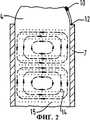
Фигура - 2 вид в плане на волновод, показанный на фигуре 1, с отображением микроволновых полей.Figure - 2 view in plan of the waveguide shown in figure 1, with the display of microwave fields.
На Фигуре 1 показан микроволновый аппликатор (1) имеющий круглый волновод (2), заполненный диэлектриком (3). Волновод (2) заканчивается на конце аппликатора (1), а часть (4), выполненная из диэлектрика, выходит из волновода и образует наконечник антенны для излучения микроволновой энергии. Тот конец волновода, который удален от наконечника (4), соединен с коаксиальным кабелем (5), который питает волновод. Внутренний проводник (6) кабеля (5) входит в диэлектрик (3) и затем проходит по оси волновода (2), чтобы обеспечить непосредственное возбуждение микроволн в волноводе (2). Внешний проводник (17) кабеля (5) соединен с внешней стенкой проводника (7) волновода. Проводник (6) заканчивается в объеме волновода, а боковой проводник (8) ответвляется радиально от проводника (6), проходит через внешнюю стенку (7) и служит для подачи микроволн в диэлектрик (3), причем магнитные поля (14) и электрические поля (15) ориентированы, как показано на фигуре 2.The Figure 1 shows a microwave applicator (1) having a circular waveguide (2) filled with a dielectric (3). The waveguide (2) ends at the end of the applicator (1), and part (4), made of a dielectric, leaves the waveguide and forms the tip of the antenna for emitting microwave energy. The end of the waveguide, which is remote from the tip (4), is connected to the coaxial cable (5) that feeds the waveguide. The inner conductor (6) of the cable (5) enters the dielectric (3) and then passes along the axis of the waveguide (2) to provide direct excitation of microwaves in the waveguide (2). The outer conductor (17) of the cable (5) is connected to the outer wall of the conductor (7) of the waveguide. The conductor (6) ends in the volume of the waveguide, and the side conductor (8) branches radially from the conductor (6), passes through the outer wall (7) and serves to supply microwaves to the dielectric (3), and the magnetic fields (14) and electric fields (15) oriented, as shown in figure 2.
Коаксиальный кабель (5) может быть заполнен воздухом, но, как иллюстрировано на фигуре 1, он заполнен диэлектриком (16), но заканчивается до конца диэлектрика (3) в волноводе (2), чтобы образовать воздушный зазор (18), который обеспечивает осевое расширение диэлектрика (16), при нагреве аппликатора в процессе лечения или стерилизации.The coaxial cable (5) can be filled with air, but, as illustrated in figure 1, it is filled with a dielectric (16), but ends to the end of the dielectric (3) in the waveguide (2) to form an air gap (18), which provides axial dielectric expansion (16), when the applicator is heated during treatment or sterilization.
Осевой размер L1 воздушного промежутка (18), и осевые размеры L2 и L3 проводника (6) в волноводе (2) с любой стороны проводника (8) выбраны с возможностью регулирования реактивного сопротивления контура, образованного проводником (8), чтобы таким образом уменьшить обратные отражения и увеличить прямое прохождение микроволн в волноводе.The axial dimension L1 of the air gap (18), and the axial dimensions L2 and L3 of the conductor (6) in the waveguide (2) on either side of the conductor (8) are selected with the possibility of regulating the reactance of the circuit formed by the conductor (8) so that way to reduce back reflections and increase the direct passage of microwaves in the waveguide.
Проводник (8) изолирован изоляцией (9) от внешней стенки волновода (7).The conductor (8) is insulated (9) from the outer wall of the waveguide (7).
Как показано на фигуре 1, на внешней стороне излучающего наконечника (4) размещена термопара (10), которая служит для измерения рабочей температуры. Кроме того, чтобы избежать дополнительного монтажа термопара (10) непосредственно соединена проводом (19) с внешним проводником (17) коаксиального кабеля (5) в точке (11) и проводом (20) снаружи стенки (7) с центральным проводником (6) кабеля (5) с помощью бокового проводника (8) и соединения (12) на его внешнем конце. Соответственно, сигнал термопары проходит по тому же самому коаксиальному кабелю (5), который подает микроволновую энергию к выходящему наконечнику (4). Для извлечения сигнала постоянного тока датчика температуры из коаксиального кабеля используется обычная схема (не показана).As shown in figure 1, on the outside of the radiating tip (4) is a thermocouple (10), which serves to measure the operating temperature. In addition, in order to avoid additional installation, the thermocouple (10) is directly connected by a wire (19) to the external conductor (17) of the coaxial cable (5) at the point (11) and a wire (20) outside the wall (7) with the central conductor (6) of the cable (5) using the side conductor (8) and the connection (12) at its outer end. Accordingly, the thermocouple signal passes through the same coaxial cable (5), which supplies microwave energy to the output tip (4). A conventional circuit (not shown) is used to extract the temperature sensor's DC signal from the coaxial cable.
Хотя это не показано на схеме, аппликатор (1) снабжен защитным покрытием, прозрачным для микроволн, выполненным из политетрафторэтилена или другого подходящего материала. Датчик температуры в виде термопары (10) вводится между покрытием и материалом диэлектрика и изолирован от материала диэлектрика.Although not shown in the diagram, the applicator (1) is provided with a protective coating, transparent to microwaves, made of polytetrafluoroethylene or other suitable material. A temperature sensor in the form of a thermocouple (10) is inserted between the coating and the dielectric material and is isolated from the dielectric material.
Предпочтительно использовать аппликатор по настоящему изобретению так же, как это описано в опубликованной заявке No. W095/04385, где аппликатор снабжен устройством ввода микроволн в полосе частот предпочтительно порядка 8-12 ГГц от микроволнового генератора и усилителя.It is preferable to use the applicator of the present invention in the same way as described in published application No. W095 / 04385, where the applicator is equipped with a microwave input device in a frequency band, preferably of the order of 8-12 GHz from a microwave generator and amplifier.
Claims (4)
Translated fromRussianApplications Claiming Priority (2)
| Application Number | Priority Date | Filing Date | Title |
|---|---|---|---|
| GB9809539.1 | 1998-05-06 | ||
| GBGB9809539.1AGB9809539D0 (en) | 1998-05-06 | 1998-05-06 | Microwave applicator |
Publications (2)
| Publication Number | Publication Date |
|---|---|
| RU2000130712A RU2000130712A (en) | 2002-10-10 |
| RU2250118C2true RU2250118C2 (en) | 2005-04-20 |
Family
ID=10831457
Family Applications (1)
| Application Number | Title | Priority Date | Filing Date |
|---|---|---|---|
| RU2000130712/14ARU2250118C2 (en) | 1998-05-06 | 1999-05-05 | Microwave applicator |
Country Status (21)
| Country | Link |
|---|---|
| US (1) | US6635055B1 (en) |
| EP (1) | EP1076522B1 (en) |
| JP (1) | JP2003505112A (en) |
| KR (1) | KR100622760B1 (en) |
| CN (1) | CN1173671C (en) |
| AT (1) | ATE270075T1 (en) |
| AU (1) | AU766177B2 (en) |
| BR (1) | BR9911016A (en) |
| CA (1) | CA2339277C (en) |
| DE (1) | DE69918430T2 (en) |
| DK (1) | DK1076522T3 (en) |
| ES (1) | ES2224656T3 (en) |
| GB (1) | GB9809539D0 (en) |
| IL (1) | IL139476A0 (en) |
| MX (1) | MXPA00010939A (en) |
| MY (1) | MY124406A (en) |
| PT (1) | PT1076522E (en) |
| RU (1) | RU2250118C2 (en) |
| TW (1) | TW464522B (en) |
| WO (1) | WO1999056642A1 (en) |
| ZA (1) | ZA200006390B (en) |
Cited By (5)
| Publication number | Priority date | Publication date | Assignee | Title |
|---|---|---|---|---|
| RU2318465C1 (en)* | 2006-04-21 | 2008-03-10 | Валерий Иванович Чиссов | Method for microwave biotissue diathermocoagulation and device for its implementation |
| RU2411019C1 (en)* | 2009-10-30 | 2011-02-10 | Александр Ильич Тома | Microwave apparatus for destruction of new growths and pathologically changed tissues |
| RU2716092C1 (en)* | 2019-07-05 | 2020-03-05 | Акционерное общество "Научно-исследовательский институт технической физики и автоматизации" (АО "НИИТФА") | Gynecological annular applicator |
| RU199430U1 (en)* | 2020-02-06 | 2020-09-01 | Общество с ограниченной ответственностью фирма "ТЕХНОСВЕТ" | Universal installation for complex destruction of biological tissue |
| RU2793811C2 (en)* | 2018-04-16 | 2023-04-06 | Эмблейшн Лимитед | Microwave applicator for cervix |
Families Citing this family (127)
| Publication number | Priority date | Publication date | Assignee | Title |
|---|---|---|---|---|
| US6306132B1 (en) | 1999-06-17 | 2001-10-23 | Vivant Medical | Modular biopsy and microwave ablation needle delivery apparatus adapted to in situ assembly and method of use |
| US7128739B2 (en) | 2001-11-02 | 2006-10-31 | Vivant Medical, Inc. | High-strength microwave antenna assemblies and methods of use |
| US6878147B2 (en) | 2001-11-02 | 2005-04-12 | Vivant Medical, Inc. | High-strength microwave antenna assemblies |
| US6752767B2 (en) | 2002-04-16 | 2004-06-22 | Vivant Medical, Inc. | Localization element with energized tip |
| US7197363B2 (en) | 2002-04-16 | 2007-03-27 | Vivant Medical, Inc. | Microwave antenna having a curved configuration |
| GB2387544B (en)* | 2002-10-10 | 2004-03-17 | Microsulis Plc | Microwave applicator |
| EP1569570B1 (en)* | 2002-11-27 | 2006-11-15 | Medical Device Innovations Limited | Tissue ablation apparatus |
| AU2003901390A0 (en)* | 2003-03-26 | 2003-04-10 | University Of Technology, Sydney | Microwave antenna for cardiac ablation |
| EP1624837A4 (en)* | 2003-05-16 | 2008-11-12 | Waverx Inc | Apparatus and method for the treatment of infectious disease in keratinized tissue |
| US7744592B2 (en)* | 2003-05-16 | 2010-06-29 | Waverx, Inc. | Apparatus and method for the treatment of infectious disease in keratinized tissue |
| GB2403148C2 (en) | 2003-06-23 | 2013-02-13 | Microsulis Ltd | Radiation applicator |
| US7311703B2 (en) | 2003-07-18 | 2007-12-25 | Vivant Medical, Inc. | Devices and methods for cooling microwave antennas |
| GB2406521B (en)* | 2003-10-03 | 2007-05-09 | Microsulis Ltd | Treatment of hollow anatomical structures |
| AU2004279676B2 (en) | 2003-10-03 | 2011-10-13 | Uk Investment Associates Llc | Device and method for the treatment of hollow anatomical structures |
| US8048101B2 (en) | 2004-02-25 | 2011-11-01 | Femasys Inc. | Methods and devices for conduit occlusion |
| US8052669B2 (en) | 2004-02-25 | 2011-11-08 | Femasys Inc. | Methods and devices for delivery of compositions to conduits |
| US9238127B2 (en) | 2004-02-25 | 2016-01-19 | Femasys Inc. | Methods and devices for delivering to conduit |
| US8048086B2 (en) | 2004-02-25 | 2011-11-01 | Femasys Inc. | Methods and devices for conduit occlusion |
| US20050209661A1 (en)* | 2004-03-22 | 2005-09-22 | Solatronix, Inc. | System and method for generating electromagnetic fields of varying shape based on a desired target |
| US20050205566A1 (en)* | 2004-03-22 | 2005-09-22 | Solatronix, Inc. Incorporation | System and method of interferentially varying electromagnetic near field patterns |
| US20070055224A1 (en)* | 2004-04-29 | 2007-03-08 | Lee Fred T Jr | Intralumenal microwave device |
| US20070016181A1 (en)* | 2004-04-29 | 2007-01-18 | Van Der Weide Daniel W | Microwave tissue resection tool |
| US8805480B2 (en)* | 2004-05-26 | 2014-08-12 | Medical Device Innovations Limited | Tissue detection and ablation apparatus and apparatus and method for actuating a tuner |
| GB2415630C2 (en) | 2004-07-02 | 2007-03-22 | Microsulis Ltd | Radiation applicator and method of radiating tissue |
| US7918795B2 (en) | 2005-02-02 | 2011-04-05 | Gynesonics, Inc. | Method and device for uterine fibroid treatment |
| US7799019B2 (en) | 2005-05-10 | 2010-09-21 | Vivant Medical, Inc. | Reinforced high strength microwave antenna |
| GB2434314B (en) | 2006-01-03 | 2011-06-15 | Microsulis Ltd | Microwave applicator with dipole antenna |
| US7815571B2 (en) | 2006-04-20 | 2010-10-19 | Gynesonics, Inc. | Rigid delivery systems having inclined ultrasound and needle |
| US9357977B2 (en) | 2006-01-12 | 2016-06-07 | Gynesonics, Inc. | Interventional deployment and imaging system |
| US10058342B2 (en) | 2006-01-12 | 2018-08-28 | Gynesonics, Inc. | Devices and methods for treatment of tissue |
| US7874986B2 (en) | 2006-04-20 | 2011-01-25 | Gynesonics, Inc. | Methods and devices for visualization and ablation of tissue |
| US11259825B2 (en) | 2006-01-12 | 2022-03-01 | Gynesonics, Inc. | Devices and methods for treatment of tissue |
| US10363092B2 (en) | 2006-03-24 | 2019-07-30 | Neuwave Medical, Inc. | Transmission line with heat transfer ability |
| US8672932B2 (en) | 2006-03-24 | 2014-03-18 | Neuwave Medical, Inc. | Center fed dipole for use with tissue ablation systems, devices and methods |
| US10595819B2 (en) | 2006-04-20 | 2020-03-24 | Gynesonics, Inc. | Ablation device with articulated imaging transducer |
| US8206300B2 (en) | 2008-08-26 | 2012-06-26 | Gynesonics, Inc. | Ablation device with articulated imaging transducer |
| US10376314B2 (en) | 2006-07-14 | 2019-08-13 | Neuwave Medical, Inc. | Energy delivery systems and uses thereof |
| US11389235B2 (en) | 2006-07-14 | 2022-07-19 | Neuwave Medical, Inc. | Energy delivery systems and uses thereof |
| CN101511295B (en) | 2006-07-14 | 2012-09-05 | 纽华沃医药公司 | Energy transfer systems and their uses |
| US20080026069A1 (en)* | 2006-07-27 | 2008-01-31 | Boston Scientific Scimed, Inc. | Particles |
| US10675298B2 (en) | 2006-07-27 | 2020-06-09 | Boston Scientific Scimed Inc. | Particles |
| US20080065059A1 (en)* | 2006-09-08 | 2008-03-13 | Marc Lukowiak | Microwave devices for transcutaneous treatments |
| US8068921B2 (en) | 2006-09-29 | 2011-11-29 | Vivant Medical, Inc. | Microwave antenna assembly and method of using the same |
| US8353901B2 (en) | 2007-05-22 | 2013-01-15 | Vivant Medical, Inc. | Energy delivery conduits for use with electrosurgical devices |
| US9023024B2 (en) | 2007-06-20 | 2015-05-05 | Covidien Lp | Reflective power monitoring for microwave applications |
| US20090012515A1 (en)* | 2007-07-06 | 2009-01-08 | Hoenig Peter A | Devices, systems and methods for treating tissues |
| US8088072B2 (en) | 2007-10-12 | 2012-01-03 | Gynesonics, Inc. | Methods and systems for controlled deployment of needles in tissue |
| US8292880B2 (en) | 2007-11-27 | 2012-10-23 | Vivant Medical, Inc. | Targeted cooling of deployable microwave antenna |
| WO2009140511A1 (en) | 2008-05-14 | 2009-11-19 | J&J Solutions, Inc. | Systems and methods for safe medicament transport |
| US10070888B2 (en) | 2008-10-03 | 2018-09-11 | Femasys, Inc. | Methods and devices for sonographic imaging |
| US9554826B2 (en) | 2008-10-03 | 2017-01-31 | Femasys, Inc. | Contrast agent injection system for sonographic imaging |
| US12171463B2 (en) | 2008-10-03 | 2024-12-24 | Femasys Inc. | Contrast agent generation and injection system for sonographic imaging |
| US11291503B2 (en) | 2008-10-21 | 2022-04-05 | Microcube, Llc | Microwave treatment devices and methods |
| US9662163B2 (en) | 2008-10-21 | 2017-05-30 | Hermes Innovations Llc | Endometrial ablation devices and systems |
| US8808281B2 (en) | 2008-10-21 | 2014-08-19 | Microcube, Llc | Microwave treatment devices and methods |
| US8500732B2 (en) | 2008-10-21 | 2013-08-06 | Hermes Innovations Llc | Endometrial ablation devices and systems |
| US8821486B2 (en) | 2009-11-13 | 2014-09-02 | Hermes Innovations, LLC | Tissue ablation systems and methods |
| US11219484B2 (en) | 2008-10-21 | 2022-01-11 | Microcube, Llc | Methods and devices for delivering microwave energy |
| US8197476B2 (en) | 2008-10-21 | 2012-06-12 | Hermes Innovations Llc | Tissue ablation systems |
| US8197477B2 (en) | 2008-10-21 | 2012-06-12 | Hermes Innovations Llc | Tissue ablation methods |
| US8382753B2 (en) | 2008-10-21 | 2013-02-26 | Hermes Innovations, LLC | Tissue ablation methods |
| US9980774B2 (en) | 2008-10-21 | 2018-05-29 | Microcube, Llc | Methods and devices for delivering microwave energy |
| EP2349045B1 (en)* | 2008-10-21 | 2014-07-16 | Microcube, LLC | Devices for applying energy to bodily tissues |
| US8540708B2 (en) | 2008-10-21 | 2013-09-24 | Hermes Innovations Llc | Endometrial ablation method |
| EP2355738B1 (en) | 2008-11-10 | 2015-08-19 | Microcube, LLC | Devices for applying energy to bodily tissues |
| US8262574B2 (en) | 2009-02-27 | 2012-09-11 | Gynesonics, Inc. | Needle and tine deployment mechanism |
| EP3549544B1 (en) | 2009-07-28 | 2021-01-06 | Neuwave Medical, Inc. | DEVICE FOR ABLATION |
| GB2474233A (en) | 2009-10-06 | 2011-04-13 | Uk Investments Associates Llc | Cooling pump comprising a detachable head portion |
| US8715278B2 (en) | 2009-11-11 | 2014-05-06 | Minerva Surgical, Inc. | System for endometrial ablation utilizing radio frequency |
| US8529562B2 (en) | 2009-11-13 | 2013-09-10 | Minerva Surgical, Inc | Systems and methods for endometrial ablation |
| US11896282B2 (en) | 2009-11-13 | 2024-02-13 | Hermes Innovations Llc | Tissue ablation systems and method |
| US9289257B2 (en) | 2009-11-13 | 2016-03-22 | Minerva Surgical, Inc. | Methods and systems for endometrial ablation utilizing radio frequency |
| US8469953B2 (en) | 2009-11-16 | 2013-06-25 | Covidien Lp | Twin sealing chamber hub |
| US8882759B2 (en) | 2009-12-18 | 2014-11-11 | Covidien Lp | Microwave ablation system with dielectric temperature probe |
| US8568404B2 (en) | 2010-02-19 | 2013-10-29 | Covidien Lp | Bipolar electrode probe for ablation monitoring |
| ES2856026T3 (en) | 2010-05-03 | 2021-09-27 | Neuwave Medical Inc | Power supply systems |
| MX348044B (en) | 2010-05-27 | 2017-05-25 | J&J Solutions Inc | Closed fluid transfer system. |
| US8672933B2 (en) | 2010-06-30 | 2014-03-18 | Covidien Lp | Microwave antenna having a reactively-loaded loop configuration |
| US8956348B2 (en) | 2010-07-21 | 2015-02-17 | Minerva Surgical, Inc. | Methods and systems for endometrial ablation |
| US9510897B2 (en) | 2010-11-05 | 2016-12-06 | Hermes Innovations Llc | RF-electrode surface and method of fabrication |
| US9192438B2 (en) | 2011-12-21 | 2015-11-24 | Neuwave Medical, Inc. | Energy delivery systems and uses thereof |
| CN104507408B (en) | 2012-06-22 | 2017-06-20 | 柯惠有限合伙公司 | For the microwave thermometric of microwave ablation system |
| US9993295B2 (en) | 2012-08-07 | 2018-06-12 | Covidien Lp | Microwave ablation catheter and method of utilizing the same |
| US9987087B2 (en) | 2013-03-29 | 2018-06-05 | Covidien Lp | Step-down coaxial microwave ablation applicators and methods for manufacturing same |
| US9901394B2 (en) | 2013-04-04 | 2018-02-27 | Hermes Innovations Llc | Medical ablation system and method of making |
| WO2015017858A1 (en) | 2013-08-02 | 2015-02-05 | J&J SOLUTIONS, INC. d.b.a CORVIDA MEDICAL | Compounding systems and methods for safe medicament transport |
| US9649125B2 (en) | 2013-10-15 | 2017-05-16 | Hermes Innovations Llc | Laparoscopic device |
| JP5947274B2 (en)* | 2013-11-13 | 2016-07-06 | 茂美 平岡 | Heating probe |
| DE102014213849A1 (en)* | 2014-07-16 | 2016-01-21 | Siemens Aktiengesellschaft | Method for transmitting a signal, signal transmission device and measuring device |
| US10624697B2 (en) | 2014-08-26 | 2020-04-21 | Covidien Lp | Microwave ablation system |
| US10813691B2 (en) | 2014-10-01 | 2020-10-27 | Covidien Lp | Miniaturized microwave ablation assembly |
| US10492856B2 (en) | 2015-01-26 | 2019-12-03 | Hermes Innovations Llc | Surgical fluid management system and method of use |
| CN107708591B (en) | 2015-04-29 | 2020-09-29 | 席勒斯科技有限公司 | Medical ablation device and method of use |
| AU2016323793B2 (en) | 2015-09-17 | 2021-03-11 | J&J SOLUTIONS, INC. d/b/a Corvida Medical | Medicament vial assembly |
| CA3001858C (en) | 2015-10-13 | 2021-03-23 | J&J SOLUTIONS, INC. d/b/a Corvida Medical | Automated compounding equipment for closed fluid transfer system |
| BR112018008233B1 (en) | 2015-10-26 | 2022-10-04 | Neuwave Medical, Inc | APPARATUS FOR FASTENING A MEDICAL DEVICE, METHOD FOR FASTENING A MEDICAL DEVICE IN A DESIRED POSITION, AND KIT |
| CN113367788B (en) | 2015-10-26 | 2024-09-06 | 纽韦弗医疗设备公司 | Energy delivery systems and uses thereof |
| US10052149B2 (en) | 2016-01-20 | 2018-08-21 | RELIGN Corporation | Arthroscopic devices and methods |
| US10813692B2 (en) | 2016-02-29 | 2020-10-27 | Covidien Lp | 90-degree interlocking geometry for introducer for facilitating deployment of microwave radiating catheter |
| GB2552921A (en)* | 2016-04-04 | 2018-02-21 | Creo Medical Ltd | Electrosurgical probe for delivering RF and microwave energy |
| US10531917B2 (en) | 2016-04-15 | 2020-01-14 | Neuwave Medical, Inc. | Systems and methods for energy delivery |
| CN109561899A (en) | 2016-04-22 | 2019-04-02 | 锐凌公司 | Arthroscope device and method |
| CN109661209A (en) | 2016-07-01 | 2019-04-19 | 锐凌公司 | Arthroscope device and method |
| US11065053B2 (en) | 2016-08-02 | 2021-07-20 | Covidien Lp | Ablation cable assemblies and a method of manufacturing the same |
| US10376309B2 (en) | 2016-08-02 | 2019-08-13 | Covidien Lp | Ablation cable assemblies and a method of manufacturing the same |
| US11197715B2 (en) | 2016-08-02 | 2021-12-14 | Covidien Lp | Ablation cable assemblies and a method of manufacturing the same |
| CN115715689B (en) | 2016-11-11 | 2025-01-17 | 杰尼索尼克斯公司 | Tissue controlled treatment and dynamic interaction and comparison with tissue and/or treatment data |
| GB2559595B (en)* | 2017-02-10 | 2021-09-01 | Creo Medical Ltd | Electrosurgical apparatus and electrosurgical instrument |
| US20190247117A1 (en) | 2018-02-15 | 2019-08-15 | Neuwave Medical, Inc. | Energy delivery devices and related systems and methods thereof |
| US20190246876A1 (en) | 2018-02-15 | 2019-08-15 | Neuwave Medical, Inc. | Compositions and methods for directing endoscopic devices |
| US11672596B2 (en) | 2018-02-26 | 2023-06-13 | Neuwave Medical, Inc. | Energy delivery devices with flexible and adjustable tips |
| GB201806193D0 (en)* | 2018-04-16 | 2018-05-30 | Emblation Ltd | Microwave application for the uterine cervix |
| ES2916523T3 (en)* | 2018-05-31 | 2022-07-01 | Bh Scient Llc | System for microwave ablation and temperature measurement during ablation |
| JP7376519B2 (en)* | 2018-08-13 | 2023-11-08 | ザ・ユニバーシティ・オブ・シドニー | Catheter ablation device with temperature monitoring |
| US20200168360A1 (en) | 2018-11-27 | 2020-05-28 | Neuwave Medical, Inc. | Systems and methods for energy delivery |
| US11832880B2 (en) | 2018-12-13 | 2023-12-05 | Neuwave Medical, Inc. | Energy delivery devices and related systems and methods thereof |
| US11832879B2 (en) | 2019-03-08 | 2023-12-05 | Neuwave Medical, Inc. | Systems and methods for energy delivery |
| CN113924057B (en)* | 2019-05-24 | 2025-01-14 | 堪萨斯州立大学研究基金会 | Minimally invasive microwave ablation device |
| US12239367B2 (en) | 2019-06-25 | 2025-03-04 | Microcube, Llc | Methods and devices for generating and delivering shaped microwave fields |
| US11554214B2 (en) | 2019-06-26 | 2023-01-17 | Meditrina, Inc. | Fluid management system |
| CN110430631B (en)* | 2019-08-09 | 2024-09-06 | 昆山九华电子设备厂 | Coaxial CTS antenna for microwave heating |
| KR20230173656A (en) | 2021-02-22 | 2023-12-27 | 오프 월드 인코포레이티드 | microwave energy applicator |
| US20230088132A1 (en) | 2021-09-22 | 2023-03-23 | NewWave Medical, Inc. | Systems and methods for real-time image-based device localization |
| US20250152264A1 (en) | 2022-02-18 | 2025-05-15 | Neuwave Medical, Inc. | Coupling devices and related systems |
| US20240285332A1 (en) | 2023-02-24 | 2024-08-29 | Neuwave Medical, Inc. | Temperature regulating devices and related systems and methods |
| US12390278B2 (en) | 2023-10-31 | 2025-08-19 | Hepta Medical SAS | Systems and methods for adaptive ablation volume prediction based on tissue temperature measurements and anatomical segmentation |
| USD1084316S1 (en) | 2023-11-20 | 2025-07-15 | Angiodynamics, Inc. | Ferrule |
Citations (2)
| Publication number | Priority date | Publication date | Assignee | Title |
|---|---|---|---|---|
| EP0459535A2 (en)* | 1988-11-21 | 1991-12-04 | Technomed Medical Systems | Apparatus for the surgical treatment of tissues by hyperthermia, preferably the prostate, with cooling means |
| WO1995004385A1 (en)* | 1993-07-27 | 1995-02-09 | Microsulis Limited | Treatment apparatus |
Family Cites Families (2)
| Publication number | Priority date | Publication date | Assignee | Title |
|---|---|---|---|---|
| FR2421628A1 (en) | 1977-04-08 | 1979-11-02 | Cgr Mev | LOCALIZED HEATING DEVICE USING VERY HIGH FREQUENCY ELECTROMAGNETIC WAVES, FOR MEDICAL APPLICATIONS |
| US4817635A (en)* | 1987-03-23 | 1989-04-04 | Duke University | Interstitial applicator with cancellation/enhancement gap |
- 1998
- 1998-05-05USUS09/674,783patent/US6635055B1/ennot_activeExpired - Fee Related
- 1998-05-06GBGBGB9809539.1Apatent/GB9809539D0/ennot_activeCeased
- 1999
- 1999-05-05AUAU38352/99Apatent/AU766177B2/ennot_activeCeased
- 1999-05-05CNCNB998010324Apatent/CN1173671C/ennot_activeExpired - Fee Related
- 1999-05-05MXMXPA00010939Apatent/MXPA00010939A/ennot_activeIP Right Cessation
- 1999-05-05KRKR1020007012395Apatent/KR100622760B1/ennot_activeExpired - Fee Related
- 1999-05-05BRBR9911016-4Apatent/BR9911016A/ennot_activeIP Right Cessation
- 1999-05-05CACA002339277Apatent/CA2339277C/ennot_activeExpired - Fee Related
- 1999-05-05MYMYPI99001764Apatent/MY124406A/enunknown
- 1999-05-05DEDE69918430Tpatent/DE69918430T2/ennot_activeExpired - Lifetime
- 1999-05-05RURU2000130712/14Apatent/RU2250118C2/ennot_activeIP Right Cessation
- 1999-05-05JPJP2000546679Apatent/JP2003505112A/ennot_activeCeased
- 1999-05-05DKDK99920972Tpatent/DK1076522T3/enactive
- 1999-05-05ILIL13947699Apatent/IL139476A0/enunknown
- 1999-05-05EPEP99920972Apatent/EP1076522B1/ennot_activeExpired - Lifetime
- 1999-05-05ATAT99920972Tpatent/ATE270075T1/ennot_activeIP Right Cessation
- 1999-05-05PTPT99920972Tpatent/PT1076522E/enunknown
- 1999-05-05ESES99920972Tpatent/ES2224656T3/ennot_activeExpired - Lifetime
- 1999-05-05WOPCT/GB1999/001398patent/WO1999056642A1/enactiveIP Right Grant
- 1999-06-08TWTW088109455Apatent/TW464522B/ennot_activeIP Right Cessation
- 2000
- 2000-11-07ZAZA200006390Apatent/ZA200006390B/enunknown
Patent Citations (2)
| Publication number | Priority date | Publication date | Assignee | Title |
|---|---|---|---|---|
| EP0459535A2 (en)* | 1988-11-21 | 1991-12-04 | Technomed Medical Systems | Apparatus for the surgical treatment of tissues by hyperthermia, preferably the prostate, with cooling means |
| WO1995004385A1 (en)* | 1993-07-27 | 1995-02-09 | Microsulis Limited | Treatment apparatus |
Cited By (5)
| Publication number | Priority date | Publication date | Assignee | Title |
|---|---|---|---|---|
| RU2318465C1 (en)* | 2006-04-21 | 2008-03-10 | Валерий Иванович Чиссов | Method for microwave biotissue diathermocoagulation and device for its implementation |
| RU2411019C1 (en)* | 2009-10-30 | 2011-02-10 | Александр Ильич Тома | Microwave apparatus for destruction of new growths and pathologically changed tissues |
| RU2793811C2 (en)* | 2018-04-16 | 2023-04-06 | Эмблейшн Лимитед | Microwave applicator for cervix |
| RU2716092C1 (en)* | 2019-07-05 | 2020-03-05 | Акционерное общество "Научно-исследовательский институт технической физики и автоматизации" (АО "НИИТФА") | Gynecological annular applicator |
| RU199430U1 (en)* | 2020-02-06 | 2020-09-01 | Общество с ограниченной ответственностью фирма "ТЕХНОСВЕТ" | Universal installation for complex destruction of biological tissue |
Also Published As
| Publication number | Publication date |
|---|---|
| WO1999056642A1 (en) | 1999-11-11 |
| EP1076522B1 (en) | 2004-06-30 |
| PT1076522E (en) | 2004-10-29 |
| CA2339277A1 (en) | 1999-11-11 |
| ATE270075T1 (en) | 2004-07-15 |
| ES2224656T3 (en) | 2005-03-01 |
| DE69918430T2 (en) | 2005-08-18 |
| KR100622760B1 (en) | 2006-09-13 |
| ZA200006390B (en) | 2001-11-07 |
| MY124406A (en) | 2006-06-30 |
| CA2339277C (en) | 2007-07-17 |
| DK1076522T3 (en) | 2004-11-01 |
| HK1032727A1 (en) | 2001-08-03 |
| IL139476A0 (en) | 2001-11-25 |
| AU3835299A (en) | 1999-11-23 |
| DE69918430D1 (en) | 2004-08-05 |
| TW464522B (en) | 2001-11-21 |
| GB9809539D0 (en) | 1998-07-01 |
| US6635055B1 (en) | 2003-10-21 |
| EP1076522A1 (en) | 2001-02-21 |
| MXPA00010939A (en) | 2002-05-07 |
| AU766177B2 (en) | 2003-10-09 |
| JP2003505112A (en) | 2003-02-12 |
| BR9911016A (en) | 2001-02-06 |
| CN1173671C (en) | 2004-11-03 |
| CN1275063A (en) | 2000-11-29 |
| KR20010034844A (en) | 2001-04-25 |
Similar Documents
| Publication | Publication Date | Title |
|---|---|---|
| RU2250118C2 (en) | Microwave applicator | |
| JP3905313B2 (en) | Radiation application equipment | |
| JP4532277B2 (en) | Microwave applicator | |
| US5301687A (en) | Microwave applicator for transurethral hyperthermia | |
| JP2742410B2 (en) | Probes, especially urethral probes for heating tissue by microwaves and measuring temperature by radiometry | |
| US6706040B2 (en) | Invasive therapeutic probe | |
| US6051018A (en) | Hyperthermia apparatus | |
| JP2003505112A5 (en) | ||
| US20040049254A1 (en) | Interstitial microwave antenna with miniaturized choke hyperthermia in medicine and surgery | |
| US20070219548A1 (en) | Microwave apparatus for controlled tissue ablation | |
| JP2010194317A (en) | Leaky-wave antenna for medical application | |
| EP0054064A1 (en) | Microwave antenna system for intracavitary insertion | |
| US7180307B2 (en) | Coaxial probe | |
| US4817635A (en) | Interstitial applicator with cancellation/enhancement gap | |
| JPS6133961Y2 (en) | ||
| HK1032727B (en) | Microwave applicator | |
| RU2089022C1 (en) | Radiator | |
| JPH0311012Y2 (en) | ||
| HK1032184A (en) | Microwave applicator | |
| JPH0363048A (en) | Microwave probe for warm heat therapeutics |
Legal Events
| Date | Code | Title | Description |
|---|---|---|---|
| MM4A | The patent is invalid due to non-payment of fees | Effective date:20060506 |