RU2248096C2 - Method and device for increasing communication channel capacity - Google Patents
Method and device for increasing communication channel capacityDownload PDFInfo
- Publication number
- RU2248096C2 RU2248096C2RU2000132322/09ARU2000132322ARU2248096C2RU 2248096 C2RU2248096 C2RU 2248096C2RU 2000132322/09 ARU2000132322/09 ARU 2000132322/09ARU 2000132322 ARU2000132322 ARU 2000132322ARU 2248096 C2RU2248096 C2RU 2248096C2
- Authority
- RU
- Russia
- Prior art keywords
- pulse
- output
- input
- pulses
- sequence
- Prior art date
Links
- 238000000034methodMethods0.000titleclaimsabstractdescription100
- 238000004891communicationMethods0.000titleclaimsdescription74
- 230000003595spectral effectEffects0.000claimsabstractdescription54
- 230000005540biological transmissionEffects0.000claimsabstractdescription12
- 238000001228spectrumMethods0.000claimsdescription38
- 230000015572biosynthetic processEffects0.000claimsdescription19
- 238000005070samplingMethods0.000claimsdescription18
- 238000006243chemical reactionMethods0.000claimsdescription11
- 238000005457optimizationMethods0.000claimsdescription11
- 238000007493shaping processMethods0.000claimsdescription4
- 238000010009beatingMethods0.000claims1
- 230000001681protective effectEffects0.000claims1
- 238000001208nuclear magnetic resonance pulse sequenceMethods0.000abstractdescription4
- 230000000694effectsEffects0.000abstract1
- 239000000126substanceSubstances0.000abstract1
- 239000002131composite materialSubstances0.000description81
- 230000014509gene expressionEffects0.000description19
- 238000004364calculation methodMethods0.000description6
- 239000000203mixtureSubstances0.000description6
- 238000013459approachMethods0.000description5
- 230000007423decreaseEffects0.000description5
- 230000005428wave functionEffects0.000description5
- 238000010586diagramMethods0.000description4
- 230000001360synchronised effectEffects0.000description4
- 230000002123temporal effectEffects0.000description4
- 238000012545processingMethods0.000description3
- 230000004044responseEffects0.000description3
- 238000012546transferMethods0.000description3
- 230000008859changeEffects0.000description2
- 230000001934delayEffects0.000description2
- 238000005516engineering processMethods0.000description2
- 238000009472formulationMethods0.000description2
- 230000036039immunityEffects0.000description2
- 239000000463materialSubstances0.000description2
- 238000004321preservationMethods0.000description2
- 230000007480spreadingEffects0.000description2
- 230000009466transformationEffects0.000description2
- 238000000844transformationMethods0.000description2
- 238000007906compressionMethods0.000description1
- 230000006835compressionEffects0.000description1
- 238000010276constructionMethods0.000description1
- 238000000354decomposition reactionMethods0.000description1
- 230000003111delayed effectEffects0.000description1
- 238000006073displacement reactionMethods0.000description1
- 238000002474experimental methodMethods0.000description1
- 230000003993interactionEffects0.000description1
- 238000013178mathematical modelMethods0.000description1
- 230000000737periodic effectEffects0.000description1
- 230000009467reductionEffects0.000description1
- 238000010561standard procedureMethods0.000description1
- 238000003786synthesis reactionMethods0.000description1
- 230000002194synthesizing effectEffects0.000description1
Images


Landscapes
- Dc Digital Transmission (AREA)
Abstract
Description
Translated fromRussianИзобретение относится к области электросвязи, преимущественно к передаче информации методами импульсной и цифровой модуляции, и может быть использовано для формирования сигналов с заданными спектральными характеристиками, обеспечивающими минимальный уровень межсимвольных искажений в канале связи.The invention relates to the field of telecommunications, mainly to the transmission of information by pulsed and digital modulation methods, and can be used to generate signals with specified spectral characteristics, providing a minimum level of intersymbol distortion in the communication channel.
Известные способы повышения пропускной способности канала связи, как правило, сводятся к формированию континуальных сигналов, для которых соотношение неопределенности удовлетворяет тем или иным критериям, обеспечивающим минимизацию межсимвольных искажений и/или повышению пропускной способности каналов связи [1, 2]. Математическое описание этих сигналов представляется нормированными функциями Эрмита или сфероидальными волновыми функциями. Аппаратная реализация таких функций затруднительна и не обеспечивает вариабельности изменения в соответствии с характеристиками самого канала связи.Known methods for increasing the bandwidth of the communication channel, as a rule, are reduced to the formation of continuum signals for which the uncertainty relation satisfies certain criteria that minimize the intersymbol distortion and / or increase the bandwidth of the communication channels [1, 2]. The mathematical description of these signals is represented by normalized Hermite functions or spheroidal wave functions. The hardware implementation of such functions is difficult and does not provide variability of changes in accordance with the characteristics of the communication channel itself.
Известен способ передачи цифровых данных с минимальным расширением спектра [3], наиболее близкий к предлагаемому изобретению. Он обеспечивает уменьшение межсимвольных искажений и сводится к формированию передаваемого в канал связи оптимизированного импульса, имеющего такие предискажения, которые обеспечивают согласованную инверсную характеристику постдетекторного фильтра нижних частот. Вносимые предискажения в передаваемый сигнал уменьшают межсимвольные искажения за счет некоторой компенсации не идеальности устройств обработки на приемной стороне. Однако формируемый таким образом сигнал только отчасти решает проблему сужения спектра, так что в канале связи межсимвольные искажения уменьшаются несущественно. В этом смысле устройства, реализующие сигналы в классе функций Эрмита или сфероидальных волновых функций, решают общую задачу, а именно: минимизируют межсимвольные искажения, возникающие при передаче информации по каналу связи. Однако в любом из этих вариантов формируемые сигналы имеют сложную форму, и потому шумы и помехи канала связи их могут существенно исказить. Сигналы же, имеющие форму, близкую к прямоугольной, наиболее устойчивы к помехам и шумам канала связи. Наличие достаточно протяженной плоской вершины в импульсе требует при тех же самых уровнях искажений большей энергии помех и шумов.A known method of transmitting digital data with minimal spreading [3], the closest to the invention. It provides a reduction in intersymbol distortion and is reduced to the formation of an optimized pulse transmitted to the communication channel having such distortions that provide a consistent inverse characteristic of the post-detector low-pass filter. The introduced bias in the transmitted signal reduces intersymbol distortion due to some compensation for not ideal processing devices on the receiving side. However, the signal generated in this way only partially solves the problem of narrowing the spectrum, so that the intersymbol distortions in the communication channel are not significantly reduced. In this sense, devices that implement signals in the class of Hermite functions or spheroidal wave functions solve the general problem, namely: minimize intersymbol distortions that occur when transmitting information over a communication channel. However, in any of these options, the generated signals have a complex shape, and therefore the noise and interference of the communication channel can significantly distort them. Signals having a shape close to rectangular are most resistant to interference and noise of the communication channel. The presence of a sufficiently extended flat peak in the pulse requires, at the same levels of distortion, more interference energy and noise.
Основным недостатком способа, описанного в [3], является то, что вносимые предискажения в передаваемый сигнал уменьшают межсимвольные искажения за счет компенсации не идеальности устройств обработки на приемной стороне. В то же время параметры передаваемого сигнала (в данной постановке) напрямую не учитывают характеристики канала связи, и поэтому на возникающие межсимвольные искажения используемая процедура предискажений напрямую ни как не влияет. Следствием этого является несущественный выигрыш в увеличении пропускной способности канала связи. Кроме того, вносимые предискажения напрямую связаны только с характеристиками постдетекторного фильтра нижних частот, а не канала связи. Это приводит к тому, что уровень межсимвольных искажений будет зависеть от типа и параметров канала связи.The main disadvantage of the method described in [3] is that the introduced distortion in the transmitted signal reduces intersymbol distortion by compensating for the not ideal processing devices on the receiving side. At the same time, the parameters of the transmitted signal (in this formulation) do not directly take into account the characteristics of the communication channel, and therefore the pre-emphasis procedure used does not directly affect the intersymbol distortions. The consequence of this is a negligible gain in increasing the bandwidth of the communication channel. In addition, the introduced pre-emphasis is directly related only to the characteristics of the post-detector low-pass filter, and not the communication channel. This leads to the fact that the level of intersymbol distortion will depend on the type and parameters of the communication channel.
Известны устройства для передачи сигналов по каналам связи с использованием различных методов импульсной модуляции. Эти устройства достаточно полно описаны, например, в [4, 5, 6, 7, 8] и являются в известной мере стандартом при применении импульсных методов модуляции. Каждое из описанных там устройств может быть использовано в качестве прототипа для того или иного метода импульсной модуляции. Общим недостатком любого из этих устройств, взятого в качестве прототипа для того или иного типа модуляции, является применение в качестве основного носителя информации прямоугольного импульса, параметры которого (амплитуда, длительность, фаза и частота следования) определяются типом модуляции. Однако, независимо от применяемого метода модуляции, спектральная плотность каждого импульса описывается функцией вида sin(ω )/ω , которая в асимптотике убывает, как 0(1/ω ), и имеет осциллирующий характер. Такое поведение спектральной характеристики приводит к тому, что прямоугольные импульсы при прохождении через канал связи размываются, и в межимпульсном пространстве появляется сигнал, так называемые межсимвольные искажения или помеха. С учетом известной связи между эффективной длительностью прямоугольного импульса носителя и его верхней частотой спектра (имеется в виду соотношение неопределенности) нельзя увеличить скорость передачи информации по каналу связи с определенной полосой пропускания без потери качества передачи информации. Очевидный на первый взгляд подход к повышению пропускной способности канала связи, связанный с уменьшением длительности импульсов носителей, неприемлем. Это связано с возрастанием уровня межсимвольных искажений, и, как следствие, на приемной стороне переданная информация будет содержать значительные ошибки.Known devices for transmitting signals over communication channels using various methods of pulse modulation. These devices are quite fully described, for example, in [4, 5, 6, 7, 8] and are to a certain extent the standard when applying pulsed modulation methods. Each of the devices described there can be used as a prototype for a particular pulse modulation method. A common drawback of any of these devices, taken as a prototype for a particular type of modulation, is the use of a rectangular pulse as the main information carrier, the parameters of which (amplitude, duration, phase and repetition rate) are determined by the type of modulation. However, irrespective of the modulation method used, the spectral density of each pulse is described by a function of the form sin (ω) / ω, which in asymptotics decreases as 0 (1 / ω) and has an oscillating character. This behavior of the spectral characteristic leads to the fact that the rectangular pulses when passing through the communication channel are eroded, and a signal appears in the interpulse space, the so-called intersymbol distortions or interference. Taking into account the known connection between the effective duration of a rectangular pulse of a carrier and its upper frequency of the spectrum (meaning the uncertainty relation), it is impossible to increase the transmission rate of information over a communication channel with a certain bandwidth without losing the quality of information transmission. At first glance, an obvious approach to increasing the throughput of a communication channel associated with a decrease in the duration of carrier pulses is unacceptable. This is due to an increase in the level of intersymbol distortions, and, as a result, on the receiving side the transmitted information will contain significant errors.
Технический результат, достигаемый предлагаемым способом повышения пропускной способности каналов связи и устройством для его реализации (варианты), заключается в формировании таких композиционных импульсных сигналов прямоугольной формы (определение композиционного сигнала приведем чуть позже), которые уменьшают межсимвольные искажения по сравнению с традиционными, общеизвестными устройствами, оперирующими с одиночными импульсами прямоугольной формы, и тем самым позволяют повысить скорость передачи информации по каналу связи (или, что то же самое, повысить пропускную способность). Кроме того, по сравнению с другими способами формирования сигналов носителей, построенных, например, на основе функций Эрмита или сфероидальных волновых функций, сохраняется высокая помехоустойчивость, присущая импульсам прямоугольной формы.The technical result achieved by the proposed method of increasing the throughput of communication channels and a device for its implementation (options) is to form such composite pulse signals of a rectangular shape (we will give the definition of a composite signal a bit later), which reduce intersymbol distortions compared to traditional, well-known devices, operating with single pulses of a rectangular shape, and thereby allow you to increase the speed of information transfer through the communication channel (silt That is the same, to increase capacity). In addition, in comparison with other methods of generating carrier signals constructed, for example, based on Hermite functions or spheroidal wave functions, the high noise immunity inherent to rectangular pulses is preserved.
Таким образом, технического результата достигают формированием сигналов с заданными спектральными характеристиками, минимизирующими межсимвольные искажения, что обеспечивает повышение пропускной способности канала связи. Кроме того, формируемые сигналы имеют высокую помехоустойчивость, т.к. относятся к классу импульсных сигналов, имеющих прямоугольную форму.Thus, the technical result is achieved by the formation of signals with predetermined spectral characteristics that minimize intersymbol distortions, which increases the throughput of the communication channel. In addition, the generated signals have high noise immunity, because belong to the class of pulse signals having a rectangular shape.
В дальнейшем в материалах заявки будет употребляться термин - композиционный сигнал. При этом под композиционным сигналом понимается последовательность прямоугольных импульсов, представляющая собой или цифровой, или импульсно-модулированный сигнал, у которого амплитуды, длительности импульсов и временные соотношения между которыми выбраны таким образом, чтобы получить заданные спектральные характеристики и/или минимизировать межсимвольные искажения.In the future, the application materials will use the term composite signal. In this case, a composite signal is understood to be a sequence of rectangular pulses, which is either a digital or pulse-modulated signal, in which the amplitudes, pulse durations, and temporal relations between them are chosen in such a way as to obtain specified spectral characteristics and / or minimize intersymbol distortions.
Указанный технический результат достигается тем, что в известном способе повышения пропускной способности каналов связи, заключающемся в построении цифровых и импульсно-модулированных сигналов с заданными спектральными характеристиками, в соответствии с предлагаемым изобретением, по заданной спектральной характеристике формируют композиционный сигнал в виде ограниченной последовательности цифровых или импульсных сигналов, число которых, их длительность, амплитудные и временные соотношения между ними выбирают по допустимой погрешности приближения к заданной спектральной характеристике, при которой уровень межсимвольных искажений и/или расширение спектра композиционного сигнала минимально с сохранением в формируемой последовательности при использовании методов импульсной модуляции передаваемой информации.The specified technical result is achieved by the fact that in the known method of increasing the throughput of communication channels, which consists in constructing digital and pulse-modulated signals with predetermined spectral characteristics, in accordance with the invention, a composite signal is generated from a given spectral characteristic in the form of a limited sequence of digital or pulse signals, the number of which, their duration, amplitude and time relationships between them are selected according to the permissible heat approximation to a given spectral characteristic, in which the level of intersymbol distortion and / or the expansion of the spectrum of the composite signal is minimal with preservation in the generated sequence when using the methods of pulsed modulation of transmitted information.
Кроме этого, технический результат достигается тем, что число импульсов в композиционном сигнале выбирают в диапазоне от 2 до n, где n - число импульсов в последовательности, определяемое из условия минимальной достаточности, обеспечивающей формирование композиционного сигнала с допустимой погрешностью приближения к заданной спектральной характеристики и сохранением защитного интервала между композиционными сигналами.In addition, the technical result is achieved by the fact that the number of pulses in the composite signal is selected in the range from 2 to n, where n is the number of pulses in the sequence, determined from the condition of minimum sufficiency, ensuring the formation of a composite signal with an allowable error of approximation to a given spectral characteristic and preservation guard interval between composite signals.
Помимо этого, технический результат достигается и тем, что амплитудные соотношения между импульсами, образующими композиционный сигнал, выбирают из условия формирования спектра композиционного сигнала, минимизирующего его расширение и/или уровень межсимвольных искажений.In addition, the technical result is achieved by the fact that the amplitude relationships between the pulses forming the composite signal are selected from the conditions for the formation of the spectrum of the composite signal, minimizing its expansion and / or the level of intersymbol distortions.
А также технический результат достигается и тем, что длительности импульсов в последовательности, образующей композиционный сигнал, выбирают из условия формирования спектра композиционного сигнала, минимизирующего его расширение и/или уровень межсимвольных искажений.And the technical result is also achieved by the fact that the duration of the pulses in the sequence forming the composite signal is selected from the conditions of formation of the spectrum of the composite signal, minimizing its expansion and / or the level of intersymbol distortion.
В дополнение к перечисленному, технический результат достигается и тем, что временные соотношения между импульсами, образующими композиционный сигнал, выбирают из условия формирования спектра композиционного сигнала, минимизирующего его расширение и/или уровень межсимвольных искажений.In addition to the above, the technical result is also achieved by the fact that the time relations between the pulses forming the composite signal are selected from the conditions for the formation of the spectrum of the composite signal, minimizing its expansion and / or the level of intersymbol distortions.
Технический результат достигается также и тем, что амплитуды импульсов в последовательности, образующей композиционной сигнал, пропорциональны текущему уровню отсчета модулирующего информационного сигнала при использовании метода амплитудно-импульсной модуляции.The technical result is also achieved by the fact that the pulse amplitudes in the sequence forming the composite signal are proportional to the current reference level of the modulating information signal when using the amplitude-pulse modulation method.
Помимо этого, технический результат достигается и тем, что длительности импульсов в последовательности, образующей композиционный сигнал, пропорциональны текущему уровню отсчета модулирующего информационного сигнала при использовании широтно-импульсной модуляции.In addition, the technical result is achieved by the fact that the pulse durations in the sequence forming the composite signal are proportional to the current reference level of the modulating information signal when using pulse-width modulation.
Кроме того, технический результат достигается и тем, что временное положение композиционного сигнала пропорционально текущему уровню отсчета модулирующего информационного сигнала при использовании метода фазоимпульсной модуляции.In addition, the technical result is achieved by the fact that the temporary position of the composite signal is proportional to the current reference level of the modulating information signal when using the phase-pulse modulation method.
Технический результат достигается также и тем, что временные соотношения между импульсами в последовательности, образующей композиционный сигнал, пропорциональны текущему уровню отсчета модулирующего информационного сигнала при использовании метода частотно-импульсной модуляции.The technical result is also achieved by the fact that the time relationships between the pulses in the sequence forming the composite signal are proportional to the current reference level of the modulating information signal when using the frequency-pulse modulation method.
А также технический результат достигается и тем, что длительности импульсов в последовательности, образующей композиционный сигнал, пропорциональны текущему числу непрерывно следующих друг за другом единиц в информационной кодовой последовательности.The technical result is also achieved by the fact that the pulse durations in the sequence forming the composite signal are proportional to the current number of units continuously following each other in the information code sequence.
Помимо этого, технический результат достигается и тем, что общая длительность последовательности импульсов, образующих композиционный сигнал при использовании кодово-импульсной модуляции, пропорциональна текущему числу непрерывно следующих друг за другом единиц в информационной кодовой группе.In addition, the technical result is achieved by the fact that the total duration of the sequence of pulses forming the composite signal using pulse-code modulation is proportional to the current number of units continuously following each other in the information code group.
И, наконец, технический результат достигается и тем, что композиционный сигнал имеет общую величину длительности, которую определяют как сумму длительностей отдельных импульсов последовательности, образующих композиционный сигнал, и временных интервалов между ними и выбирают из условия обеспечения максимальной пропускной способности канала связи, при заданном допустимом уровне межсимвольных искажений и величине защитного интервала между соседними композиционными сигналами.And, finally, the technical result is achieved by the fact that the composite signal has a total duration, which is defined as the sum of the durations of the individual pulses of the sequence forming the composite signal and the time intervals between them and is selected from the condition of ensuring the maximum bandwidth of the communication channel, for a given allowable the level of intersymbol distortion and the value of the guard interval between adjacent composite signals.
Указанный технический результат достигается реализующим заявленный способ устройством, повышающим пропускную способность каналов связи, и его вариантами.The specified technical result is achieved by implementing the claimed method of a device that increases the throughput of communication channels, and its variants.
Устройство по первому варианту, отличающемуся от выбранного прототипа тем, что выход устройства дискретизации входного информационного сигнала подключен ко входам устройства выборки-хранения и формирователя импульса запуска, выход которого подключен к входам n параллельно включенных формирователей импульсов заданной длительности, причем выход первого из них через первое масштабирующее устройство подключено к первому входу сумматора, а выходы n-1 остальных формирователей импульсов заданной длительности через соответствующие n-1 устройств задержки и n-1 масштабирующих устройств подключены к остальным n-1 входам сумматора, выход которого подключен к входу управляемого усилителя, управляющий вход которого подключен к выходу устройства выборки-хранения, причем управляющий вход устройства выборки-хранения подключен к выходу формирователя импульса сброса, вход которого подключен к входу n-го масштабирующего устройства.The device according to the first embodiment, which differs from the selected prototype in that the output of the input information signal sampling device is connected to the inputs of the fetch-storage device and the trigger pulse shaper, the output of which is connected to the inputs of n pulse shapers of a given duration, the output of the first of them through the first the scaling device is connected to the first input of the adder, and the outputs n-1 of the remaining pulse shapers of a given duration through the corresponding n-1 devices delays and n-1 scaling devices are connected to the remaining n-1 inputs of the adder, the output of which is connected to the input of a controlled amplifier, the control input of which is connected to the output of the sample-storage device, and the control input of the sample-storage device is connected to the output of the reset pulse generator, whose input is connected to the input of the nth scaling device.
Устройство по второму варианту, отличающемуся от выбранного прототипа тем, что выход устройства дискретизации входного информационного сигнала подключен к входам устройства выборки-хранения и формирователя импульса заданной длительности, выход которого подключен к входу первого масштабирующего устройства, а входы остальных n-1 масштабирующих устройств подключены к выходу формирователя импульса заданной длительности через соответствующие n-1 устройств задержки, выходы каждого из n масштабирующих устройств подключены к n входам сумматора, выход которого соединен с входом управляемого усилителя, управляющий вход которого подключен к выходу устройства выборки-хранения, управляющий вход которого через устройство формирования импульса сброса подключен к входу n-го масштабирующего устройства, выход управляемого усилителя подключен к входу устройства преобразования напряжения во временной интервал.The device according to the second embodiment, which differs from the selected prototype in that the output of the input information signal discretization device is connected to the inputs of the sample-storage device and a pulse shaper of a given duration, the output of which is connected to the input of the first scaling device, and the inputs of the remaining n-1 scaling devices are connected to the output of the pulse shaper of a given duration through the corresponding n-1 delay devices, the outputs of each of the n scaling devices are connected to n inputs of the sum an ora whose output is connected to the input of the controlled amplifier, the control input of which is connected to the output of the sampling-storage device, the control input of which is connected to the input of the nth scaling device through the device for generating a reset pulse, the output of the controlled amplifier is connected to the input of the voltage conversion device in the time interval .
Устройство по третьему варианту, отличающемуся от выбранного прототипа тем, что в него дополнительно введены устройство формирования импульса запуска, на вход которого поступает фазо-частотно-импульсно модулированная информационная последовательность, выход которого подключен к входам n параллельно включенных формирователей импульсов заданной длительности, причем выход первого из них через первое масштабирующее устройство подключен к первому входу сумматора, а выходы n-1 остальных формирователей импульсов заданной длительности через соответствующие n-1 устройств задержки и n-1 масштабирующих устройств подключены к остальным n-1 входам сумматора, выход которого является выходом устройства.The device according to the third embodiment, which differs from the selected prototype in that it additionally includes a trigger pulse generating device, the input of which is supplied with a phase-frequency-pulse-modulated information sequence, the output of which is connected to the inputs of n parallel pulse shapers of a given duration, the output of the first of them through the first scaling device is connected to the first input of the adder, and the outputs n-1 of the remaining pulse shapers of a given duration Without the corresponding n-1 delay devices and n-1 scaling devices, they are connected to the remaining n-1 inputs of the adder, the output of which is the output of the device.
Устройство по четвертому варианту, отличающемуся от выбранного прототипа тем, что в него дополнительно введены устройство формирования импульса запуска и устройство преобразования временного интервала в напряжение, на входы которых поступает кодово-импульсная информационная последовательность, выход устройства преобразования временного интервала в напряжение подключен к входу устройства выборки-хранения, выход которого подключен к управляющему входу управляемого усилителя, выход формирователя импульса запуска подключен через первое масштабирующее устройство к первому входу сумматора, остальные n-1 входов которого подключены к выходам n-1 параллельно включенных масштабирующих устройств, входы которых через соответствующие устройства задержки подключены к выходу устройства формирования импульса запуска, выход сумматора через управляемый усилитель подключен к устройству преобразования напряжения во временной интервал, вход n-го масштабирующего устройства через дополнительное устройство задержки подключен к входу формирователя импульса сброса, выход которого подключен к управляющему входу устройства выборки-хранения.The device according to the fourth embodiment, which differs from the selected prototype in that it additionally includes a device for generating a start pulse and a device for converting a time interval into voltage, the inputs of which receive a code-pulse information sequence, the output of the device for converting a time interval into voltage is connected to the input of the sampling device -storage, the output of which is connected to the control input of a controlled amplifier, the output of the trigger pulse shaper is connected through the first scaling device to the first input of the adder, the remaining n-1 inputs of which are connected to the outputs of n-1 parallel-connected scaling devices, the inputs of which are connected through the corresponding delay devices to the output of the trigger pulse generating device, the adder output is connected to the voltage conversion device through a controlled amplifier the time interval, the input of the nth scaling device through an additional delay device is connected to the input of the reset pulse shaper, the output of which connected to the control input of the sample-and-hold device.
Технический результат достигается, таким образом, за счет формирования композиционного сигнала в виде конечной последовательности цифровых или импульсных сигналов, число которых, их длительность, амплитудные и временные соотношения между ними выбирают по допустимой погрешности приближения к заданной спектральной характеристике, при которой уровень межсимвольных искажений и/или расширение спектра композиционного сигнала минимально. В этом случае суммарный спектр последовательности импульсных или цифровых сигналов может быть наиболее близким к спектрам сигналов, формируемых с использованием функций Эрмита, или сфероидальных волновых функций, или инверсной характеристики канала связи. При этом в формируемой последовательности, при использовании методов импульсной модуляции, сохраняется передаваемая информация.The technical result is achieved, thus, due to the formation of a composite signal in the form of a finite sequence of digital or pulse signals, the number of which, their duration, amplitude and time relationships between them are selected by the permissible error of approximation to a given spectral characteristic, at which the level of intersymbol distortion and / or the spreading of the spectrum of the composite signal is minimal. In this case, the total spectrum of the sequence of pulsed or digital signals may be closest to the spectra of the signals generated using the Hermite functions, or spheroidal wave functions, or the inverse characteristic of the communication channel. Moreover, in the generated sequence, using the methods of pulse modulation, the transmitted information is stored.
Рассмотрим более детально реализацию предлагаемого способа на примере амплитудно-импульсной модуляции (АИМ). Ниже, при описании конкретных устройств, реализующих известные методы импульсной и цифровой модуляции, будут приведены необходимые пояснения для каждого из этих способов.Let us consider in more detail the implementation of the proposed method as an example of amplitude-pulse modulation (AIM). Below, when describing specific devices that implement the known methods of pulse and digital modulation, the necessary explanations will be given for each of these methods.
При передаче информации по каналу связи методом АИМ информационная составляющая сигнала присутствует в амплитудах импульсов, которые обозначим через аq. Запишем общее выражение для сигнала в видеWhen transmitting information over the communication channel by the AIM method, the information component of the signal is present in the pulse amplitudes, which we denote by aq . We write the general expression for the signal in the form

где текущие отсчеты импульсов взяты в моменты времени τq.where the current samples of the pulses are taken at time instants τq .
Обычно импульсная последовательность (1) синхронна в том смысле, чтоUsually the pulse sequence (1) is synchronous in the sense that
τq=qT, q=0,± 1,± 2,...τq = qT, q = 0, ± 1, ± 2, ...
При этом на приемное устройство поступает последовательностьIn this case, the sequence

гдеWhere

Сумма в выражении (3) характеризует погрешность за счет межсимвольных искажений. Она обусловлена влиянием соседних импульсов на текущий импульс.The sum in expression (3) characterizes the error due to intersymbol distortions. It is due to the influence of neighboring pulses on the current pulse.
Заметим, что прямоугольные импульсы наиболее распространены в методах передачи информации по каналам связи. Из рассмотрения выражения (1) вроде бы следует, что уменьшением длительности несущего импульса можно повысить скорость передачи информации. Однако этот путь неприемлем из-за ограниченности полосы пропускания самого канала связи. Ограничение такого вида учитывается в виде соотношения неопределенности, которое для импульса прямоугольной формы имеет видNote that rectangular pulses are most common in methods of transmitting information through communication channels. From the consideration of expression (1), it seems to follow that by reducing the duration of the carrier pulse, the information transfer rate can be increased. However, this path is unacceptable due to the limited bandwidth of the communication channel itself. A restriction of this kind is taken into account in the form of an uncertainty relation, which for a rectangular pulse has the form

где Δ T - эффективная длительность импульсного сигнала x(t), Fmax - верхняя частота в спектре прямоугольного импульса, определенные энергетическим методом на заданном уровне. Как правило, это обычно 90-95% от полной энергии сигнала.where Δ T is the effective duration of the pulse signal x (t), Fmax is the upper frequency in the spectrum of a rectangular pulse, determined by the energy method at a given level. As a rule, this is usually 90-95% of the total signal energy.
Неравенство (4) является, по сути, ограничением, накладываемым на скорость передачи информации по каналу связи с полосой пропускания W.Inequality (4) is, in fact, a restriction imposed on the speed of information transmission over a communication channel with a bandwidth W.
Уровень межсимвольных искажений, при использовании в качестве носителя информации прямоугольных импульсов, будет значительным. Это связано с тем, что скорость убывания "хвоста" спектральной плотности каждого импульса в асимптотике убывает как O(1/ω ) и имеет осциллирующий характер. Упомянутые свойства поведения спектральной характеристики приводят к тому, что значительная часть энергии импульса оказывается за пределами полосы пропускания канала связи. Математически это интерпретируется следующим образом. Спектральная характеристика умножается на конечное частотное окно (которое есть по сути частотная характеристика канала связи). Если это произведение подвергнуть преобразованию Фурье, то окажется, что прямоугольный импульс на выходе канала связи трансформировался в импульс с затянутыми передним и задним фронтами. Здесь не приводятся соответствующие математические выкладки ввиду известности этого явления.The level of intersymbol distortion, when using rectangular pulses as the information carrier, will be significant. This is due to the fact that the rate of decrease of the "tail" of the spectral density of each pulse in the asymptotics decreases as O (1 / ω) and has an oscillating character. The mentioned properties of the behavior of the spectral characteristics lead to the fact that a significant part of the pulse energy is outside the bandwidth of the communication channel. Mathematically, this is interpreted as follows. The spectral response is multiplied by the final frequency window (which is essentially the frequency response of the communication channel). If this product is subjected to the Fourier transform, it turns out that the rectangular pulse at the output of the communication channel was transformed into a pulse with extended leading and trailing edges. The corresponding mathematical calculations are not given here due to the fame of this phenomenon.
Таким образом, для повышения пропускной способности канала связи необходимо уменьшать уровень межсимвольных искажений посредством формирования таких сигналов, у которых энергия за пределами Fmax минимальна. Этого можно достичь, например, синтезом импульсов на основе функций Эрмита или сфероидальных волновых функций.Thus, in order to increase the throughput of the communication channel, it is necessary to reduce the level of intersymbol distortion by generating such signals for which the energy outside Fmax is minimal. This can be achieved, for example, by synthesis of pulses based on Hermite functions or spheroidal wave functions.
В настоящем способе описывается другой подход, основанный на построении композиционного сигнала, состоящего из некоторой конечной последовательности импульсов прямоугольной формы.The present method describes another approach based on the construction of a composite signal consisting of a finite sequence of rectangular pulses.
Будем придерживаться следующей формы изложения. Все необходимые выкладки проведем на основе сравнения свойств одиночного прямоугольного импульса и предлагаемого композиционного сигнала.We will adhere to the following form of presentation. We will carry out all the necessary calculations based on a comparison of the properties of a single rectangular pulse and the proposed composite signal.
На фиг.1 показан типовой и композиционный сигналы. Последний из них представляет собой последовательность (в качестве примера) из трех отдельных импульсов.Figure 1 shows a typical and composite signals. The last one is a sequence (as an example) of three separate pulses.
Для стандартного импульса (фиг.1а) единственным варьируемым параметром, обеспечивающим оптимизацию по отношению к характеристикам канала связи и, следовательно, скорости передачи, является его длительность Tc. Спектральная характеристика у такого импульса асимптотически убывает как O(1/ω ) и представляет собой осциллирующую функцию типа sin(ω )/ω .For a standard pulse (figa), the only variable parameter that provides optimization with respect to the characteristics of the communication channel and, therefore, the transmission speed, is its duration Tc . The spectral characteristic of such a pulse asymptotically decreases as O (1 / ω) and is an oscillating function of the type sin (ω) / ω.
Для композиционного сигнала, показанного на фиг.1б, варьируемыми параметрами являются:For the composite signal shown in figb, variable parameters are:
τi- сдвиг между соседними импульсами длительностью Δ ti (также изменяемый параметр),τi is the shift between adjacent pulses of duration Δ ti (also a variable parameter),
mi - коэффициент масштабирования дополнительных импульсов, находящихся слева и справа от базового (центрального), и, наконец,mi - the scaling factor of additional pulses located to the left and right of the base (central), and, finally,
n - число импульсов в композиции.n is the number of pulses in the composition.
Общая длительность сложного композиционного сигнала равна Tc, и она необязательно должна быть равна длительности исходного одиночного прямоугольного импульса.The total duration of the composite composite signal is Tc , and it does not have to be equal to the duration of the original single rectangular pulse.
Следует отметить, что простой одиночный импульс прямоугольной формы в технике связи часто связывают во временной области с прямоугольным окном данных, которому в частотной области отвечает ядро сходимости Дирихле ряда Фурье. Для композиционного сигнала масштабирующие коэффициенты m, число импульсов n и сдвиговые соотношения τ , представляющие композиционный сигнал, позволяют при той же самой интерпретации считать, что формируемое таким образом дискретно-решетчатое окно данных с устанавливаемыми характеристиками во временной области позволяет строить ядра сходимости ряда Фурье с заданными свойствами.It should be noted that a simple single pulse of a rectangular shape in communication technology is often associated in the time domain with a rectangular data window, which in the frequency domain corresponds to the Dirichlet convergence kernel of the Fourier series. For a composite signal, the scaling coefficients m, the number of pulses n, and the shear relations τ representing the composite signal allow us to assume, with the same interpretation, that the discrete-lattice data window thus formed with set characteristics in the time domain allows us to construct convergence kernels of the Fourier series with given properties.
Опишем математическую модель композиционного импульсного сигнала во временной области. Для описания будем пользоваться определением rect-функции и примем следующие свойства модели:We describe the mathematical model of a composite pulsed signal in the time domain. For description, we will use the definition of a rect function and accept the following model properties:
- сигнал симметричен относительно нулевого отсчета времени;- the signal is symmetrical with respect to the zero time reference;
- композиционный сигнал продолжен также в область отрицательных значений времени.- the composite signal is also continued to the region of negative time values.
Без потери общности рассуждений, значение аq(0) можно принять равным 1.Without loss of generality of reasoning, the value of aq (0) can be taken equal to 1.
Отметим, что длительность композиционного сигнала, содержащего n=2k+1 импульсов, равна (см. фиг.1б)Note that the duration of the composite signal containing n = 2k + 1 pulses is equal to (see figb)

Рассмотрим частный случай: n=1. ТогдаConsider the special case: n = 1. Then

Спектр композиционного сигнала вырождается в спектр одиночного импульсаThe spectrum of the composite signal degenerates into the spectrum of a single pulse

Общий случай: n=2k+1. Композиционный сигнал во временной области описывается такGeneral case: n = 2k + 1. The composite signal in the time domain is described as follows

Как легко заметить, простым введением общего множителя, равного аk, описание (6) обобщается на отсчет произвольной амплитуды.As it is easy to notice, by simple introduction of a common factor equal to ak , description (6) is generalized to a reference of arbitrary amplitude.
На основании теоремы о спектре смещенного во времени импульса и производя группировку однотипных членов, запишемBased on the theorem on the spectrum of a time-shifted pulse and grouping the same type of terms, we write

Для частного случая, когда τi=0, mi=1 (i=1, k-1), модуль спектральной плотности в 2k+1 раз больше модуля спектральной плотности одиночного импульса. Скорость спадания спектральных составляющих та же, что и для одиночного импульса.For the special case when τi = 0, mi = 1 (i = 1, k-1), the spectral density modulus is 2k + 1 times greater than the single-pulse spectral density modulus. The decay rate of the spectral components is the same as for a single pulse.
С другой стороны (альтернативный предельный случай), при Δ ti=Δ t и τi=τ и выборе величины τ =2π ω /(2k+1) суммарная спектральная плотность равна нулю. При промежуточных значениях временного сдвига, масштабирующих коэффициентах и длительностей импульсов, составляющих композиционный сигнал, спектральная плотность определяется как геометрическая сумма спектральных составляющих отдельных импульсов.On the other hand (alternative limiting case), for Δ ti = Δ t and τi = τ and choosing the value τ = 2π ω / (2k + 1), the total spectral density is zero. With intermediate values of the time shift, scaling coefficients, and pulse durations that make up the composite signal, the spectral density is defined as the geometric sum of the spectral components of individual pulses.
Введем безразмерный масштабирующий коэффициентWe introduce the dimensionless scaling factor

В случае, если μi>1, то имеет место сжатие импульса длительностью Δ ti по отношению к сигналу с длительностью Δ t1. Если же μi<1 - растяжение импульса, т.е. изменение его временного масштаба.If μi > 1, then there is a compression of the pulse with a duration Δ ti with respect to a signal with a duration Δ t1 . If μi <1 is the pulse extension, i.e. change in its time scale.
С учетом сделанных замечаний запишем выражение для спектра композиционного сигналаBased on the comments made, we write the expression for the spectrum of the composite signal

или с учетом формулы Эйлераor taking into account the Euler formula

Преобразуем произведение тригонометрических функций в сумму и учтем также, что из определения μi следует μ0=1 (т.к. μ0=Δ t1/Δ t1) и что m0=1, τ0=0 для центрального импульса композиционного сигнала. Тогда последнее выражение представим в видеWe transform the product of trigonometric functions into a sum and also take into account that μ0 = 1 follows from the definition of μi (since μ0 = Δ t1 / Δ t1 ) and that m0 = 1, τ0 = 0 for the central momentum compositional signal. Then the last expression can be represented as

В полученном выражении и далее в тексте описания, где будут использоваться отрицательные индексы, примем по определению следующее а-i≡ аi.In the resulting expression and further in the description text, where negative indices will be used, we assume by definition the following a-i- ai .
Затем поступим следующим образом. Умножим и разделим каждый член суммы наThen we proceed as follows. Multiply and divide each member of the sum by

В итоге получимAs a result, we get

Выражение (8) есть отрезок тригонометрического ряда. Более того, после приведения его к виду (9), где в качестве базисных функций выступают функции видаExpression (8) is a segment of the trigonometric series. Moreover, after reducing it to the form (9), where the functions of the form

получен отрезок обобщенного ряда Фурье.a segment of the generalized Fourier series is obtained.
Система базисных функций (10) ортогональна на частотном интервале (-∞ , ∞ ) и может быть приведена к ортонормированной системе при соответствующем выборе коэффициентов βi. В силу конечности сигнала s(t) и конечности его энергии можно представить его в виде обобщенного ряда Фурье в системе базисных функций вида (10). Если при этом спектр сигнала ограничен (в нашем случае полосой пропускания канала связи), то используя только конечное число членов разложения, можно аппроксимировать совокупный спектр композиционного сигнала, заданного, например, в виде некоторой функции или ограничений. Вид функции и требования к ней или те или иные ограничения могут быть заданы исходя из общей технической задачи синтеза сигнала с заданными свойствами. Безусловно, замена ряда конечной суммой позволяет построить лишь приближенное описание аппроксимируемого условия или функции, т.е. с некоторой погрешностью.The system of basis functions (10) is orthogonal on the frequency interval (-∞, ∞) and can be reduced to an orthonormal system with an appropriate choice of the coefficients βi . Due to the finiteness of the signal s (t) and the finiteness of its energy, it can be represented as a generalized Fourier series in a system of basis functions of the form (10). If the signal spectrum is limited (in our case, the bandwidth of the communication channel), then using only a finite number of decomposition terms, we can approximate the total spectrum of the composite signal specified, for example, in the form of some function or restrictions. The type of function and the requirements for it, or certain restrictions can be set based on the general technical task of synthesizing a signal with specified properties. Of course, replacing the series with a finite sum allows us to construct only an approximate description of the approximated condition or function, i.e. with some error.
Важно отметить, что каждый член суммы (9) в системе базисных функций вида (10) ассоциирован с конкретным импульсом, представленным в композиционном сигнале. Поэтому соответствующим выбором варьируемых параметров суммы, таких как mi, τi, Δ ti и n, можно построить оптимальный отрезок ряда, обеспечивающий заданную точность приближения к формируемой спектральной характеристике композиционного сигнала, и ассоциировать его с некоторым набором rect-функций во временной области.It is important to note that each member of the sum (9) in the system of basis functions of the form (10) is associated with a specific impulse represented in the composite signal. Therefore, by appropriate choice of variable sum parameters, such as mi , τi , Δ ti and n, it is possible to construct an optimal segment of the series that provides a given accuracy of approaching the generated spectral characteristic of the composite signal and associate it with a certain set of rect functions in the time domain .
Если в качестве нормы системных базисных функций (10) выбратьIf, as the norm of the system basis functions (10), we choose

то S(ω ) представляется конечным числом членов ряда в базисе вида (10) какthen S (ω) is represented by a finite number of members of the series in a basis of the form (10) as
S(ω )=Soc(ω ,T)+Sош(ω ),S (ω) = Soc (ω, T) + SОш (ω),
где Soc(ω ,T) - спектральная характеристика сигнала s(t) длительностью Т. Здесь под Sош(ω ) понимаем составляющую, определяемую как ошибка аппроксимации спектральной характеристики.where Soc (ω, T) is the spectral characteristic of the signal s (t) of duration T. Here, by SОш (ω) we mean the component defined as the approximation error of the spectral characteristic.
В силу ортогональности базисных функций спектры Soc(ω ,T) и Sош(ω ) не перекрываются, и их энергии, т.е. квадраты норм, складываютсяDue to the orthogonality of the basis functions, the spectra Soc (ω, T) and SОш (ω) do not overlap, and their energies, i.e. squares of norms add up

За абсолютную меру ошибки аппроксимации можно принять, например, расстояние, равное норме сигнала ошибки, т.е. если WS(ω ) - энергетический спектр сигнала s(t), то по теореме РелеяFor the absolute measure of the approximation error, one can take, for example, the distance equal to the norm of the error signal, i.e. if WS (ω) is the energy spectrum of the signal s (t), then by the Rayleigh theorem

Формирование произвольной спектральной характеристики композиционного сигнала описанным выше способом может быть реализовано на основе двух подходов. Первый из них фактически описан выше и сводится, по сути, к решению задачи аппроксимации заданной спектральной характеристики с нормой ошибки, определяемой точностью приближения. Далее осуществляется пересчет полученных расчетных параметров базисных функций отрезка ряда в амплитудно-временные соотношения композиционного сигнала.The formation of an arbitrary spectral characteristic of a composite signal in the manner described above can be implemented on the basis of two approaches. The first of them is actually described above and essentially reduces to solving the problem of approximating a given spectral characteristic with an error rate determined by the accuracy of approximation. Next, the calculated parameters of the basis functions of the segment of the series are recalculated into the amplitude-time relations of the composite signal.
Второй подход состоит в построении классической вариационной задачи с ограничениями. Необходимо найти оптимальные соотношения между mi, τi, Δ ti для ∀ i∈ 1,n, такие, чтобы обеспечивалось формирование заданной спектральной характеристики в частотной области.The second approach is to construct a classical variational problem with constraints. It is necessary to find the optimal relations between mi , τi , Δ ti for ∀ i∈ 1, n, such that the formation of a given spectral characteristic in the frequency domain is ensured.
Критериями оптимизации могут быть, опять же, допустимая ошибка приближения к заданной спектральной характеристике или же, скажем, минимум энергии спектральных составляющих, лежащих за пределами некоторой верхней частоты спектра (например, это может быть верхняя частота полосы пропускания канала связи).The optimization criteria can be, again, the permissible error of approaching a given spectral characteristic or, say, the minimum energy of the spectral components lying outside a certain upper frequency of the spectrum (for example, this may be the upper frequency of the transmission channel bandwidth).
В любом случае, оба подхода решают одну и ту же задачу минимизации уровня межсимвольных искажений и, следовательно, повышения пропускной способности канала связи при заданных на него характеристиках.In any case, both approaches solve the same problem of minimizing the level of intersymbol distortions and, consequently, increasing the throughput of the communication channel with the given characteristics.
Рассмотрим в качестве примера 1 формирование композиционного сигнала, состоящего из трех импульсов (n=3 и фиксировано). Считаем также, что композиционный сигнал симметричен относительно нулевого отсчета времени. ЗапишемLet us consider as an example 1 the formation of a composite signal consisting of three pulses (n = 3 and fixed). We also consider that the composite signal is symmetrical with respect to the zero time reference. We write

Примем также условие m0=1, что не снижает общности результата. ТогдаWe also accept the condition m0 = 1, which does not reduce the generality of the result. Then

Варьируемые параметры Δ t1, Δ t2, τ1, m1.Variable parameters Δ t1 , Δ t2 , τ1 , m1 .
Определим критерий оптимальности искомых параметров Δ t1, Δ t2, τ1, m1 на основе минимальности энергии спектра, например за частотой первого нуля главного лепестка спектральной характеристики, равной ω0=2π .We define an optimality criterion for the desired parameters Δ t1 , Δ t2 , τ1 , m1 based on the minimum energy of the spectrum, for example, behind the frequency of the first zero of the main lobe of the spectral characteristic equal to ω0 = 2π.
Эксперимент показал, что значения варьируемых параметров при данной постановке и условиях задачи следующие: Δ t1=0.511, Δ t2=0.415, τ1=0.671, m1=0.237.The experiment showed that the values of the varied parameters for this formulation and the conditions of the problem are as follows: Δ t1 = 0.511, Δ t2 = 0.415, τ1 = 0.671, m1 = 0.237.
Спектральная характеристика композиционного сигнала для данных параметров показана на фиг.2. Результаты математического моделирования показывают, что даже для этой простейшей модели удалось существенно снизить уровень спектральных составляющих за пределами выбранной верхней частоты спектра. Отметим, что приведенная мощность спектральных составляющих композиционного сигнала равна 0.047. В то же время для одиночного импульса она составляет величину 0.088.The spectral characteristic of the composite signal for these parameters is shown in figure 2. The results of mathematical modeling show that even for this simplest model, it was possible to significantly reduce the level of spectral components beyond the selected upper frequency of the spectrum. Note that the reduced power of the spectral components of the composite signal is 0.047. At the same time, for a single pulse, it amounts to 0.088.
Для сопоставимости, полная мощность спектральных составляющих, найденная в диапазоне от [0, 20 ω0] (что для численных расчетов эквивалентно ∞ ), была принята за 1.For comparability, the total power of the spectral components, found in the range from [0, 20 ω0 ] (which is equivalent to ∞ for numerical calculations), was taken as 1.
Некоторые замечания к выбору системы ограничений для вариации Δ t1, Δ t2, τ1, m1. Вариационная задача строится на том факте, что нам известна полоса пропускания канала связи. Таким образом, критерий минимизации, например уровня спектральных составляющих за некоторой частотой, связывается обязательно (или привязывается) к верхней частоте среза частотной характеристики канала связи.Some remarks on the choice of a system of constraints for the variation of Δ t1 , Δ t2 , τ1 , m1 . The variational problem is based on the fact that we know the bandwidth of the communication channel. Thus, the minimization criterion, for example, the level of spectral components at a certain frequency, is bound (or tied) to the upper cutoff frequency of the frequency response of the communication channel.
Кроме того, решение однопараметрической оптимизационной задачи не является наилучшим. Может быть сформулирована и многопараметрическая оптимизационная задача. Однако, учитывая иллюстративность приведенного примера и то, что приводимые рассуждения являются частью описания заявки на предлагаемый способ, на этом и остановимся.In addition, the solution of a one-parameter optimization problem is not the best. A multi-parameter optimization problem can also be formulated. However, given the illustrative nature of the above example and the fact that the reasoning given is part of the description of the application for the proposed method, we will dwell on this.
Пример 2. Описание устройства реализующего данный способ повышения пропускной способности канала связи при использовании метода амплитудно-импульсной модуляции.Example 2. Description of the device that implements this method of increasing the bandwidth of the communication channel when using the method of amplitude-pulse modulation.
Технический результат достигается тем, что в устройство для реализации способа повышения пропускной способности канала связи при использовании метода амплитудно-импульсной модуляции, содержащее устройство дискретизации входного информационного сигнала, выход которого подключен к входам устройства выборки-хранения и формирователю импульса запуска, выход которого подключен к входам n параллельно включенных формирователей импульсов заданной длительности, причем выход первого из них через первое масштабирующее устройство подключен к первому входу сумматора, а выходы n-1 остальных формирователей импульсов заданной длительности через соответствующие n-1 устройств задержки и n-1 масштабирующих устройств подключены к остальным n-1 входам сумматора, выход которого подключен ко входу управляемого усилителя, управляющий вход которого подключен к выходу устройства выборки-хранения, причем управляющий вход устройства выборки-хранения подключен к выходу формирователя импульса сброса, вход которого подключен ко входу n-го масштабирующего устройства.The technical result is achieved by the fact that in a device for implementing a method for increasing the throughput of a communication channel using the method of amplitude-pulse modulation, comprising a device for sampling the input information signal, the output of which is connected to the inputs of the sampling-storage device and a driver pulse trigger, the output of which is connected to the inputs n parallel pulse shapers of a given duration, and the output of the first of them through the first scaling device is connected the first adder input, and the outputs n-1 of the remaining pulse shapers of a given duration through the corresponding n-1 delay devices and n-1 scaling devices are connected to the remaining n-1 inputs of the adder, the output of which is connected to the input of the controlled amplifier, the control input of which is connected to the output sampling-storage device, and the control input of the sampling-storage device is connected to the output of the reset pulse shaper, the input of which is connected to the input of the nth scaling device.
На чертеже фиг.3 представлена блок-схема устройства для реализации способа повышения пропускной способности канала связи при использовании метода амплитудно-импульсной модуляции.The drawing of figure 3 presents a block diagram of a device for implementing a method of increasing the throughput of a communication channel using the method of amplitude-pulse modulation.
Устройство для реализации способа повышения пропускной способности канала связи при использовании метода амплитудно-импульсной модуляции содержит устройство дискретизации входного информационного сигнала 1, формирователь импульса запуска 2, n формирователей импульсов заданной длительности 3, 4,... , n+2, n-1 устройств задержки n+3, n+4,... , 2n+1, n масштабирующих устройств 2n+2, 2n+3,... , 3n+1, формирователь импульса сброса 3n+2, устройство выборки-хранения 3n+3, сумматор 3n+4 и управляемый усилитель 3n+5.A device for implementing a method for increasing the throughput of a communication channel using the amplitude-pulse modulation method comprises a sampling device for the
Выход управляемого усилителя является выходом устройства.The output of the controlled amplifier is the output of the device.
Рассмотрим более детально реализацию предлагаемого способа повышения пропускной способности канала связи при использовании метода амплитудно-импульсной модуляции.Let us consider in more detail the implementation of the proposed method for increasing the throughput of the communication channel when using the method of amplitude-pulse modulation.
Входной аналоговый информационный сигнал s(t) после выполнения операции дискретизации с помощью устройства дискретизации 1 преобразуется к видуThe input analog information signal s (t) after performing the sampling operation using the

где sq - отсчеты сигнала s(t), взятые в моменты времени tq=qTдиск. Здесь Тдиск - период синхронной последовательности дискретизированных импульсов, определяемый в соответствии с теоремой отсчетов (теоремой Котельникова). В силу ограничения на длительность отсчетных импульсов, связанного с конечностью полосы пропускания канала связи (см. неравенство (4)), его временная протяженность составляет Δ t. Строго говоря, здесь должно выполняться неравенство, т.е. не должно быть превышено это значение.where sq are the samples of the signal s (t) taken at time instants tq = qTdisk . Here Tdisk is the period of the synchronized sequence of discretized pulses, determined in accordance with the sampling theorem (Kotelnikov theorem). Due to the restriction on the duration of the counting pulses associated with the finiteness of the passband of the communication channel (see inequality (4)), its temporal length is Δ t. Strictly speaking, the inequality must hold here, i.e. this value should not be exceeded.
Амплитуды отсчетов сигнала sq сохраняются с помощью устройства выборки-хранения 3n+3. Дискретизированный сигнал поступает на устройство формирования импульса запуска 2. Последнее формирует импульс запуска по переднему фронту отсчета сигнала sq.The amplitudes of the samplesq q are stored using the 3n + 3 sample-storage device. The discretized signal is supplied to the trigger
В целях упрощения выкладок и сокращения объема записей формул, дальнейшие рассуждения и описание проведем применительно только к текущему отсчету сигнала sq.In order to simplify the calculations and reduce the volume of formula entries, further discussion and description will be carried out as applied only to the current sample signalq q .
Примем также условие, что середина текущего импульса отсчета находится в нуле временной оси, т.е. τq=0.We also accept the condition that the middle of the current reference pulse is at the zero of the time axis, i.e. τq = 0.
Учитывая, что параметры канала связи известны, а также сформулирована и решена для конкретных условий оптимизационная задача, то нам известны следующие параметры формируемого композиционного сигнала, а именно: n - число импульсов в композиции, временные соотношения τi между каждым импульсом и соответственно масштабные коэффициенты mi для каждого из них.Considering that the parameters of the communication channel are known, and the optimization problem is formulated and solved for specific conditions, we know the following parameters of the generated composite signal, namely: n is the number of pulses in the composition, the temporal relations τi between each pulse, and accordingly the scale factors mi for each of them.
Импульс запуска, полученный на выходе формирователя импульса запуска 2, синхронно запускает n формирователей импульсов заданной длительности 3, 4,... , n+2. На выходе каждого из них формируются импульсы одинаковой (например, единичной) амплитуды. Причем импульс длительностью Δ t1 появляется на выходе описываемого устройства (конечно, в трансформированном виде после ряда преобразований над ним) сразу после отсчета sk. Позиционные соотношения импульсов различной длительности и их число строго фиксировано на основе результатов решения оптимизационной задачи для композиционного сигнала. Далее, импульс длительностью Δ t1 с выхода формирователя импульсов 3 поступает на масштабирующее устройство 2n+2, которое устанавливает необходимое значение амплитуды данной компоненты композиционного сигнала. Таким образом, на первый вход сумматора 3n+4 поступает сигналThe trigger pulse received at the output of the

Следует отметить, что этот импульс, полученный на выходе формирователя импульсов 2, как бы проходит через устройство с нулевой временной задержкой, т.е. τ0=0.It should be noted that this pulse received at the output of
Аналогичным образом рассматриваются и другие каналы формирования импульсных составляющих композиционного сигнала, так что на выходе сумматора 3n+4 имеем сигнал видаOther channels for generating the pulsed components of the composite signal are considered in a similar way, so that at the output of the adder 3n + 4 we have a signal of the form

Сигнал отвечающий выражению (15) поступает на управляемый усилитель 3n+5, коэффициент передачи которого определяется подаваемым на его управляющий вход уровнем напряжения, формируемым устройством выборки-хранения 3n+3. Итак, на выходе управляемого усилителя 3n+5, получаем сигналThe signal corresponding to expression (15) is fed to a controlled amplifier 3n + 5, the transmission coefficient of which is determined by the voltage level supplied to its control input by a 3n + 3 sample-storage device. So, at the output of the controlled amplifier 3n + 5, we get a signal

Необходимость в хранении уровня напряжения на выходе устройства выборки-хранения 3n+3 отпадает сразу же после окончания сигнала, прошедшего через устройство задержки 2n+1, имеющего наибольшее из всех других устройств задержки время задержки (это канал формирования последнего импульса в композиционном сигнале). Поэтому по заднему фронту этого сигнала генерируется формирователем импульса сброса 3n+2 импульс сброса для устройства выборки-хранения 3n+3.The need to store the voltage level at the output of the 3n + 3 sampling and storage device disappears immediately after the end of the signal that has passed through the 2n + 1 delay device, which has the longest delay time of all other delay devices (this is the channel for generating the last pulse in the composite signal). Therefore, on the trailing edge of this signal, a
Отметим, что формируемый таким образом композиционный сигнал имеет существенно более качественные спектральные характеристики, ориентированные на уменьшение уровня межсимвольных искажений. Поэтому его длительность может быть выбрана меньшей, чем длительность одиночного импульса прямоугольного типа, при сопоставимом уровне межсимвольных искажений в канале связи. Учитывая же то обстоятельство, что сам период следования импульсов не является главным определяющим фактором, влияющим на величину верхней частоты спектра, а только на уровень межсимвольных искажений, можно таким образом период следования композиционного сигнала также уменьшить. Итак, период следования композиционного сигнала по сравнению с периодом следования одиночного меньше. Это позволяет, при тех же характеристиках канала связи, повысить верхнюю частоту спектра передаваемого сигнала и тем самым дополнительно повысить пропускную способность канала связи и с этой стороны. Как отмечалось выше, основным ограничителем пропускной способность канала связи являются межсимвольные помехи. С учетом того обстоятельства, что спектральные характеристики композиционного сигнала согласованы с параметрами канала связи, то их уровень ниже, и это позволяет повысить пропускную способность канала связи.Note that the composite signal generated in this way has significantly better spectral characteristics aimed at reducing the level of intersymbol distortion. Therefore, its duration can be chosen shorter than the duration of a single pulse of a rectangular type, with a comparable level of intersymbol distortion in the communication channel. Considering the fact that the pulse repetition period itself is not the main determining factor affecting the value of the upper frequency of the spectrum, but only the level of intersymbol distortions, it is thus possible to reduce the repetition period of the composite signal. So, the repetition period of the composite signal in comparison with the repetition period of a single signal is less. This allows, with the same characteristics of the communication channel, to increase the upper frequency of the spectrum of the transmitted signal and thereby further increase the throughput of the communication channel from this side. As noted above, intersymbol interference is the main limiter on the throughput of a communication channel. Given the fact that the spectral characteristics of the composite signal are consistent with the parameters of the communication channel, their level is lower, and this allows to increase the throughput of the communication channel.
Пример 3. Описание устройства, реализующего данный способ повышения пропускной способности канала связи при использовании метода широтно-импульсной модуляции.Example 3. Description of the device that implements this method of increasing the bandwidth of the communication channel when using the method of pulse-width modulation.
Технический результат достигается тем, что в устройство для реализации способа повышения пропускной способности канала связи при использовании метода широтно-импульсной модуляции, содержащее устройство дискретизации входного информационного сигнала, выход которого подключен к входам устройства выборки-хранения и формирователя импульса заданной длительности, выход которого подключен к входу первого масштабирующего устройства, а входы остальных n-1 масштабирующих устройств подключены к выходу формирователя импульса заданной длительности через соответствующие устройства задержки, выходы каждого из n масштабирующих устройств подключены к n входам сумматора И, выход которого соединен с входом управляемого усилителя, управляющий вход которого подключен к выходу устройства выборки-хранения, управляющий вход которого через устройство формирования импульса сброса подключено к входу n-го масштабирующего устройства, выход управляемого усилителя подключен ко входу устройства преобразования напряжения во временной интервал.The technical result is achieved by the fact that in a device for implementing a method for increasing the bandwidth of a communication channel using the pulse width modulation method, the device contains a sampling device for the input information signal, the output of which is connected to the inputs of the sample-storage device and a pulse shaper of a given duration, the output of which is connected to the input of the first scaling device, and the inputs of the remaining n-1 scaling devices are connected to the output of the pulse shaper for a given duration through the corresponding delay devices, the outputs of each of the n scaling devices are connected to the n inputs of the adder AND, the output of which is connected to the input of the controlled amplifier, the control input of which is connected to the output of the sample-storage device, the control input of which is connected to the input n through the device for generating a reset pulse of the scaling device, the output of the controlled amplifier is connected to the input of the voltage conversion device in the time interval.
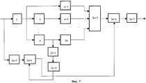
На чертеже фиг.4 представлена блок-схема устройства для реализации способа повышения пропускной способности канала связи при использовании метода широтно-импульсной модуляции.The drawing of figure 4 presents a block diagram of a device for implementing a method of increasing the throughput of a communication channel using the pulse width modulation method.
Устройство для реализации способа повышения пропускной способности канала связи при использовании метода широтно-импульсной модуляции содержит устройство дискретизации входного информационного сигнала 1, формирователь импульса заданной длительности 2, n-1 устройств задержки 3, 4,... , n+1, n масштабирующих устройств n+2, n+3,... 2n+1, формирователь импульса сброса 2n+2, устройство выборки-хранения 2n+3, сумматор 2n+4, управляемый усилитель 2n+5, устройство преобразования напряжения во временной интервал 2n+6.A device for implementing a method for increasing the bandwidth of a communication channel using the pulse width modulation method comprises a sampling device for the
Выход устройства преобразования напряжения во временной интервал является выходом устройства.The output of the voltage conversion device in the time interval is the output of the device.
Опишем реализацию предлагаемого способа повышения пропускной способности канала связи при использовании широтно-импульсной модуляции.We describe the implementation of the proposed method for increasing the bandwidth of the communication channel when using pulse-width modulation.
Предварительно приведем некоторые материалы технического характера, которые нами будут использованы в дальнейшем. Их целью является подтверждение того факта, что реализуемое устройство в итоге формирует последовательность импульсов, составляющую композиционный сигнал, и имеющий свойства, аналогичные последовательности, формируемой устройством при использовании амплитудно-импульсной модуляции.First, we present some technical materials that we will use in the future. Their goal is to confirm the fact that the device being implemented ultimately generates a pulse sequence that makes up the composite signal and has properties similar to the sequence generated by the device using pulse-amplitude modulation.
В общем случае, при использовании стандартного способа формирования широтно-импульсной последовательности на базе импульсов прямоугольного типа последняя описывается выражениемIn general, when using the standard method for generating a pulse-width sequence based on rectangular pulses, the latter is described by the expression

где аq - амплитуда текущего отсчета модулирующего информационного сигнала; Т - период следования отсчетов и Δ t - длительность модулируемого импульса при значении информационного сигнала аq=1. Носителем информации при таком способе модуляции является длительность текущего импульса. Так же, как и для амплитудно-импульсной модуляции, спектральная характеристика каждого импульса последовательности типа (17) описывается функцией вида sin(ω )/ω . Кроме того, ширина спектра зависит от уровня модулирующего сигнала, в то время как для амплитудно-импульсной модуляции этой зависимости нет.where aq is the amplitude of the current reading of the modulating information signal; T is the period of the samples and Δ t is the duration of the modulated pulse at the value of the information signal aq = 1. The storage medium with this modulation method is the duration of the current pulse. As for amplitude-pulse modulation, the spectral characteristic of each pulse of a sequence of type (17) is described by a function of the form sin (ω) / ω. In addition, the width of the spectrum depends on the level of the modulating signal, while for amplitude-pulse modulation this dependence is not.
Так же, как и в предыдущем случае, при использовании амплитудно-импульсной модуляции сигнала межсимвольные искажения в канале связи возникают из-за взаимодействия "хвостов" спектральных характеристик, что также ограничивает скорость передачи информации.As in the previous case, when using amplitude-pulse modulation of the signal, intersymbol distortions in the communication channel arise due to the interaction of the “tails” of the spectral characteristics, which also limits the transmission rate of information.
Вполне очевидно, что в рассматриваемом методе модуляции оптимизация спектральных характеристик модулированного информационного импульса также необходима. Представим q отсчет широтно-модулированного импульса в виде композиционного сигнала, показанного на фиг.5. Для наглядности и простоты выкладок использована модель: аq=1 и симметричность относительно нулевого отсчета времени. Итак, композиционный сигнал для q отсчета имеет видIt is quite obvious that in the modulation method under consideration, optimization of the spectral characteristics of a modulated information pulse is also necessary. Imagine q reading the pulse-width modulated pulse in the form of a composite signal shown in Fig.5. For clarity and simplicity of calculations, the model was used:q = 1 and symmetry with respect to the zero time reference. So, the composite signal for q readout has the form

Выражение для спектра композиционного сигнала, с учетом теоремы о спектре смещенного во времени импульса, таковоThe expression for the spectrum of the composite signal, taking into account the theorem on the spectrum of a time-shifted pulse, is

или переходя от произведения тригонометрических функций к сумме и учитывая, что m0=1, запишемor passing from the product of trigonometric functions to the sum and taking into account that m0 = 1, we write

Полученное выражение является в некотором смысле аналогом полученного нами ранее выражения для случая амплитудно-импульсной модуляции. Умножив и разделив каждый член суммы на коэффициентThe obtained expression is, in a sense, an analogue of the expression we obtained earlier for the case of amplitude-pulse modulation. Multiplying and dividing each member of the sum by a coefficient

получимwe get

Полученный отрезок тригонометрического ряда вида (20) по сути аналогичен отрезку ряда, описываемого выражением (9).The obtained segment of the trigonometric series of the form (20) is essentially similar to the segment of the series described by expression (9).
Таким образом, это также является отрезком обобщенного ряда Фурье, со всеми вытекающими отсюда свойствами, о которых говорилось ранее. Вариационная или аппроксимационная задачи строятся на основе тех же принципов, которые были сформулированы ранее.Thus, this is also a segment of the generalized Fourier series, with all the ensuing properties, which were mentioned earlier. Variational or approximation problems are built on the basis of the same principles that were formulated earlier.
Приведем описание реализации предлагаемого способа повышения пропускной способности канала связи при использовании широтно-импульсной модуляции.Here is a description of the implementation of the proposed method to increase the bandwidth of the communication channel when using pulse-width modulation.
Входной аналоговый информационный сигнал s(t) после выполнения операции дискретизации с помощью устройства дискретизации 1, преобразуется к виду (14).The input analog information signal s (t) after performing the sampling operation using the
Амплитуды отсчетов сигнала sq сохраняются с помощью устройства выборки-хранения 2n+3. Дискретизированный сигнал поступает на формирователь импульса 2 длительностью Δ t1, которое формирует импульс запуска по переднему фронту отсчета сигнала sq.The amplitudes of the samplesq q are stored using the sampling-
В целях упрощения выкладок и сокращения объема записей формул дальнейшие рассуждения и описание так же, как и для примера 2, проведем применительно только к текущему отсчету сигнала sq. Примем также условие, что середина текущего импульса отсчета находится в нуле временной оси, т.е. τq=0.In order to simplify the calculations and reduce the volume of formula entries, further considerations and description, as well as for example 2, will be carried out as applied only to the current sample signalq . We also accept the condition that the middle of the current reference pulse is at the zero of the time axis, i.e. τq = 0.
Учитывая, что параметры канала связи известны, а также сформулирована и решена для конкретных условий оптимизационная задача, то нам известны следующие параметры формируемого композиционного сигнала, а именно: n - число импульсов в композиции, временные соотношения τi между каждым импульсом и соответственно масштабные коэффициенты mi для каждого из импульсов.Considering that the parameters of the communication channel are known, and the optimization problem is formulated and solved for specific conditions, we know the following parameters of the generated composite signal, namely: n is the number of pulses in the composition, the temporal relations τi between each pulse, and accordingly the scale factors mi for each of the pulses.
Амплитуда выходного сигнала формирователя импульсов 2 длительностью Δ t1произвольна и фиксирована (условно ее можно принять равной единице) и подается через n-1 устройств задержки 3, 4,... , n+1 на соответствующие им n-1 масштабирующих устройств n+3, n+4,... , 2n+1. Причем масштабирующее устройство n+2 подключено своим входом непосредственно к выходу формирователя импульса 2 длительностью Δ t1.The amplitude of the output signal of the
Так же, как и в предыдущем примере, нам известны позиционные соотношения, т.е. времена задержек каждого импульса в композиции τi и масштабные коэффициенты mi, а также и их число n. Заметим, что формулируемая вариационная задача в данном случае несколько отличается по числу варьируемых параметров. Так, временная длительность импульсов, составляющих композиционный сигнал, одна и та же и равна Δ t1.As in the previous example, we know the positional relations, i.e. the delay times of each pulse in the composition τi and scale factors mi , as well as their number n. Note that the variational problem formulated in this case is somewhat different in the number of varied parameters. So, the time duration of the pulses making up the composite signal is the same and equal to Δ t1 .
Выходы n масштабирующих устройств n+2, n+3,... ,2n+1 подключены к n входам сумматора 2n+4. На его выходе формируется сигнал видаThe outputs of n scaling devices n + 2, n + 3, ..., 2n + 1 are connected to the n inputs of the adder 2n + 4. At its output, a signal of the form

который подается на управляемый усилитель 2n+5, коэффициент передачи которого определяется уровнем сигнала, присутствующем на его управляющем входе. Этот сигнал формируется на выходе устройства выборки-хранения 2n+3. Устройство выборки-хранения 2n+3 управляется формирователем импульса сброса 2n+2, вход которого подключен к выходу устройства задержки n+1. Таким образом, на выходе управляемого усилителя 2n+5 формируется последовательностьwhich is fed to a controlled amplifier 2n + 5, the transmission coefficient of which is determined by the level of the signal present at its control input. This signal is generated at the output of the sampling-

подаваемая на устройство преобразования напряжения во временной интервал 2n+6, на выходе которого имеемsupplied to the voltage conversion device in the

Таким образом, получена последовательность, представляющая собой композиционный сигнал с требуемыми свойствами.Thus, a sequence is obtained that is a composite signal with the desired properties.
По окончании импульса длительностью Δ t1 на устройстве задержки n+1 формируется импульс сброса по заднему фронту формирователем импульса сброса 2n+2. Сигнал сброса обнуляет устройство выборки-хранения 2n+3, и тем самым оно подготавливается к формированию следующего композиционного сигнала.At the end of a pulse of duration Δ t1 , a reset pulse is generated on the trailing edge of the delay device n + 1 by a
Выводы для рассмотренного метода импульсной модуляции аналогичны выводам, сделанным для примера 2.The conclusions for the considered pulse modulation method are similar to the conclusions made for example 2.
Пример 4. Описание устройства, реализующего данный способ повышения пропускной способности канала связи при использовании методов фазо-частотно-импульсной модуляции.Example 4. Description of the device that implements this method of increasing the bandwidth of the communication channel when using methods of phase-frequency-pulse modulation.
Технический результат достигается тем, что в устройство для реализации способа повышения пропускной способности канала связи при использовании методов фазо-частотно-импульсной модуляции, отличающееся тем, что в него дополнительно введены устройство формирования импульса запуска, на вход которого поступает фазо- частотно-импульсно модулированная информационная последовательность, выход которого подключен к входам n параллельно включенных формирователей импульсов заданной длительности, причем выход первого из них подключен к первому входу сумматора, а выходы n-1 остальных формирователей импульсов заданной длительности через соответствующие n-1 устройств задержки подключены к остальным n-1 входам сумматора, выход которого является выходом устройства.The technical result is achieved by the fact that in the device for implementing the method of increasing the throughput of the communication channel using phase-frequency-pulse-modulation methods, characterized in that it additionally introduces a trigger pulse generating device, to the input of which the phase-frequency-pulse modulated information a sequence whose output is connected to the inputs of n parallel pulse shapers of a given duration, and the output of the first of them is connected to the first at the input of the adder, and the outputs n-1 of the remaining pulse shapers of a given duration through the corresponding n-1 delay devices are connected to the remaining n-1 inputs of the adder, the output of which is the output of the device.
На чертеже фиг.6 представлена блок-схема устройства для реализации способа повышения пропускной способности канала связи при использовании методов фазо-частотно-импульсной модуляции.The drawing of Fig.6 shows a block diagram of a device for implementing a method of increasing the bandwidth of a communication channel when using methods of phase-frequency-pulse modulation.
Устройство для реализации способа повышения пропускной способности канала связи при использовании методов фазо-частотно-импульсной модуляции содержит устройство формирования импульса запуска 1, n формирователей импульсов заданной длительности 2, 3, ... ,n+1, n-1 устройств задержки n+2, n+3,... ,2n, сумматор 2n+1.A device for implementing a method for increasing a communication channel throughput using phase-frequency-pulse modulation methods comprises a trigger
Выход сумматора является выходом устройства.The output of the adder is the output of the device.
Известные способы формирования фазо-импульсных или частотно-импульсных сигналов сводятся к формированию последовательности видаKnown methods for generating phase-pulse or frequency-pulse signals are reduced to the formation of a sequence of the form

где аq - амплитуда текущего отсчета модулирующего информационного сигнала; Т - период следования импульсов в синхронной последовательности при значении информационного сигнала аq=1. Для импульсных методов модуляции переносчиком информации является периодическая синхронная последовательность прямоугольных импульсов с отличительными признаками, свойственными тем или иным видам модуляции. Например, в том случае, когда аq=1 (q=1, 2,... ), присутствует последовательность с периодом Т, или, иначе говоря, каждый последующий импульс задерживается на одно и то же время, так что его фаза относительно тактовых моментов времени фиксирована и равна нулю. В том же случае, если используется фазо-импульсная модуляция, то фаза прямоугольных импульсов в последовательности изменяется в соответствии с модулирующим информационным сигналом.where aq is the amplitude of the current reading of the modulating information signal; T is the pulse repetition period in a synchronous sequence with the value of the information signal aq = 1. For pulsed modulation methods, the information carrier is a periodic synchronous sequence of rectangular pulses with distinctive features characteristic of one or another type of modulation. For example, in the case when aq = 1 (q = 1, 2, ...), there is a sequence with a period T, or, in other words, each subsequent pulse is delayed at the same time, so that its phase is relatively clock times are fixed and equal to zero. In the same case, if phase-pulse modulation is used, then the phase of the rectangular pulses in the sequence changes in accordance with the modulating information signal.
Для частотно-импульсной модуляции позиционное положение импульсов в последовательности также зависит от уровня модулирующего сигнала. Причем частота следования импульсов в последовательности определяется уровнем информационного сигнала.For pulse frequency modulation, the positional position of the pulses in the sequence also depends on the level of the modulating signal. Moreover, the pulse repetition rate in the sequence is determined by the level of the information signal.
Объединение обеих методов модуляции в одном устройстве основывается на полной идентичности обработки их сигналов при формировании композиционной последовательности импульсов.The combination of both modulation methods in one device is based on the complete identity of the processing of their signals during the formation of a composite sequence of pulses.
Каждый отдельный импульс последовательности (24) имеет спектральную характеристику, описываемую функцией вида sin(ω )/ω . Отличия в используемых методах модуляции по отношению к рассмотренным выше приводит к тому, что все фазо- и частотно-модулированные импульсы в передаваемой последовательности совершенно идентичны по своему описанию, как во временной области, так и частотной. Т.е. спектральные характеристики каждого отдельного импульса одинаковы. Однако сами методы модуляции, приводящие к позиционному смещению импульсов в последовательности, пропорциональному их модулирующему параметру, все-таки, как и для рассмотренных выше методов, приводят к возникновению межсимвольных искажений. Их уровень, собственно, и ограничивает пропускную способность канала связи при заданном качестве передачи информации. Таким образом, и здесь есть необходимость в оптимизации спектральных характеристик передаваемого сигнала.Each individual pulse of sequence (24) has a spectral characteristic described by a function of the form sin (ω) / ω. Differences in the modulation methods used with respect to those considered above lead to the fact that all phase and frequency modulated pulses in the transmitted sequence are completely identical in their description, both in the time domain and in the frequency domain. Those. the spectral characteristics of each individual pulse are the same. However, the modulation methods themselves, leading to a positional shift of the pulses in the sequence proportional to their modulating parameter, nevertheless, as for the methods considered above, lead to the appearance of intersymbol distortions. Their level, in fact, limits the bandwidth of the communication channel for a given quality of information transfer. Thus, there is also a need to optimize the spectral characteristics of the transmitted signal.
Ниже мы не будем приводить подробного математического описания спектральных характеристик последовательности фазо-частотно-модулированных сигналов. Во многом оно совпадает с рассмотренными выше, а спектральные характеристики каждого отдельного импульса по своему описанию отвечают описанию спектральной характеристики обычного прямоугольного импульса с соответствующими характеристиками.Below we will not provide a detailed mathematical description of the spectral characteristics of a sequence of phase-frequency-modulated signals. In many respects, it coincides with the ones considered above, and the spectral characteristics of each individual pulse in their description correspond to the description of the spectral characteristics of an ordinary rectangular pulse with the corresponding characteristics.
Заменим текущий отсчет фазо-частотно-импульсного сигнала композиционной последовательностью.We replace the current reference of the phase-frequency-pulse signal with a compositional sequence.
Примем следующие свойства модели композиционного сигнала для q отсчета. Во-первых, позиционное смещение центрального импульса по оси времени равно аq, а сама композиционная последовательность импульсов симметрична относительно точки t=аq. Таким образом, композиционный сигнал описывается выражениемLet us take the following properties of the composite signal model for q reference. First, the positional displacement of the central impulse along the time axis is equal to aq , and the compositional sequence of pulses is symmetric with respect to the point t = aq . Thus, the composite signal is described by the expression

При нахождении спектра композиционного сигнала следует учесть, что смещение последовательности по временной оси на величину t=аq приводит только к изменению фазового спектра, в то время как амплитудный спектр остается тем же самым, что и для импульса, середина которого находится в нуле временной оси. Поэтому для упрощения вида математических выражений сместим композиционную последовательность на величину t=аq. Итак, запишемWhen finding the spectrum of the composite signal, it should be taken into account that shifting the sequence along the time axis by t = aq leads only to a change in the phase spectrum, while the amplitude spectrum remains the same as for the pulse, the middle of which is at the zero of the time axis . Therefore, to simplify the form of mathematical expressions, we shift the compositional sequence by t = aq . So we write

Спектр композиционного сигнала с учетом теоремы о спектре смещенного во времени импульса и свойств симметрии после некоторых преобразований имеет видThe spectrum of the composite signal, taking into account the theorem on the spectrum of the time-shifted pulse and the symmetry properties after some transformations, has the form

где μi=Δ t1/Δ ti+1 (I=0, 1, 2,... ) - безразмерный масштабирующий коэффициент. Выражение (26) во многом схоже с (8), за исключением того, что все масштабирующие коэффициенты mi=1 (i=1, k-1). После преобразования произведения тригонометрических функций в сумму и учитывая, что μ0=1, τ0=0, соотношение (26) перепишем так:where μi = Δ t1 / Δ ti + 1 (I = 0, 1, 2, ...) is the dimensionless scaling factor. Expression (26) is in many respects similar to (8), except that all scaling factors are mi = 1 (i = 1, k-1). After converting the product of trigonometric functions into a sum and taking into account that μ0 = 1, τ0 = 0, we rewrite relation (26) as follows:

Умножим и разделим каждый член суммы наMultiply and divide each member of the sum by

получимwe get

Очевидно, что и в этом случае получен отрезок тригонометрического ряда в системе базисных функций (10).Obviously, in this case as well, a segment of the trigonometric series in the system of basis functions (10) was obtained.
Выбор параметров n=2k+1, Δ ti, τi осуществляется аналогичным образом, как и для рассмотренных выше примеров.The choice of parameters n = 2k + 1, Δ ti , τi is carried out in the same way as for the above examples.
Опишем реализацию предлагаемого способа повышения пропускной способности канала связи при использовании фазо-, частотно-импульсной модуляции.We describe the implementation of the proposed method for increasing the throughput of a communication channel when using phase, frequency and pulse modulation.
На вход устройства формирования импульса запуска 1 поступает фазо-частотно-модулированная последовательность. Устройство формирования импульса запуска 1 генерирует импульс по переднему фронту поступившего сигнала и запускает n формирователей импульсов заданной длительности 2, 3,... n+1. На выходе устройства формирования импульса 2 генерируется импульс длительностью Δ t1 с фиксированной (например, единичной) амплитудой и который подается на первый вход сумматора 2n+1. Остальные n-1 устройств формирования импульсов 3, 4,... , n+1 генерируют импульсы длительностью Δ t2, Δ t3 и т.д. Также с фиксированной амплитудой, равной амплитуде на выходе устройства формирования импульса 2.At the input of the device for generating a
Упомянутые n-1 импульсов, через соответствующие n-1 устройств задержки n+2, n+3,... ,2n, поступают на остальные n-1 входов сумматора 2n+1. На его выходе формируется сигналThe mentioned n-1 pulses, through the corresponding n-1 delay devices n + 2, n + 3, ..., 2n, go to the remaining n-1 inputs of the adder 2n + 1. A signal is generated at its output.

В общем случае, когда смещение центрального импульса в композиционной последовательности произвольно, в выражении (28) числитель модифицируется так: t-(aq+τi-1).In the general case, when the shift of the central pulse in the compositional sequence is arbitrary, in the expression (28) the numerator is modified as follows: t- (aq + τi-1 ).
Выводы относительно полученного таким образом композиционного сигнала остаются теми же, что делались ранее в примерах реализации тех или иных устройств формирования композиционного сигнала для соответствующих им методов модуляции.The conclusions regarding the composite signal thus obtained remain the same as were done earlier in the examples of the implementation of various devices for generating the composite signal for the corresponding modulation methods.
Пример 5. Описание устройства, реализующего данный способ повышения пропускной способности канала связи при использовании метода кодово-импульсной модуляции.Example 5. Description of a device that implements this method of increasing the throughput of a communication channel using the code-pulse modulation method.
Технический результат достигается тем, что в устройство для реализации способа повышения пропускной способности канала связи при использовании метода кодово-импульсной модуляции, отличающееся тем, что в него дополнительно введены устройство формирования импульса запуска и устройство преобразования временного интервала в напряжение, на входы которых поступает кодово-импульсная информационная последовательность, выход устройства преобразования временного интервала в напряжение подключен к входу устройства выборки-хранения, выход которого подключен к управляющему входу управляемого усилителя, выход формирователя импульса запуска подключен через первое масштабирующее устройство к первому входу сумматора, остальные n-1 входов которого подключены к выходам n-1 параллельно включенных масштабирующих устройств, входы которых через соответствующие устройства задержки подключены к выходу устройства формирования импульса запуска, выход сумматора через управляемый усилитель подключен к устройству преобразования напряжения во временной интервал, вход n-го масштабирующего устройства через дополнительное устройство задержки подключен к входу формирователя импульса сброса, выход которого подключен к управляющему входу устройства выборки-хранения.The technical result is achieved by the fact that in the device for implementing the method of increasing the throughput of the communication channel using the code-pulse modulation method, characterized in that it additionally includes a device for generating a start pulse and a device for converting a time interval into voltage, the inputs of which are coded pulse information sequence, the output of the device for converting a time interval into a voltage is connected to the input of the sample-storage device, the output is connected to the control input of the controlled amplifier, the output of the trigger pulse shaper is connected through the first scaling device to the first input of the adder, the remaining n-1 inputs of which are connected to the outputs of n-1 parallel-connected scaling devices, the inputs of which are connected through the corresponding delay devices to the output of the shaping device start pulse, the output of the adder through a controlled amplifier is connected to a device for converting voltage into a time interval, the input of the nth scaled its device through an additional delay device is connected to the input of the reset pulse shaper, the output of which is connected to the control input of the sample-storage device.
На чертеже фиг. 7 представлена блок-схема устройства для реализации способа повышения пропускной способности канала связи при использовании метода кодово-импульсной модуляции.In the drawing of FIG. 7 is a block diagram of a device for implementing a method for increasing a communication channel throughput using a pulse-code modulation method.
Устройство для реализации способа повышения пропускной способности канала связи при использовании метода кодово-импульсной модуляции содержит устройство формирования импульса запуска 1, n-1 устройств задержки 2, 3,... , n, n масштабирующих устройств n+1, n+2,... , 2n, дополнительное устройство задержки 2n+1, формирователь импульса сброса 2n+2, устройство преобразования временного интервала в напряжение 2n+3, устройство выборки-хранения 2n+4, сумматор 2n+5, управляемый усилитель 2n+6, устройство преобразования напряжения во временной интервал 2n+7.A device for implementing a method for increasing the throughput of a communication channel using the pulse-code modulation method comprises a device for generating a
Выход устройства преобразования напряжения во временной интервал является выходом устройства.The output of the voltage conversion device in the time interval is the output of the device.
Входной аналоговый сигнал с помощью кодирующего устройства преобразуется в последовательность двоичных чисел, передаваемых со скоростью один двоичный разряд каждые Т секунд. Совокупность 1 и 0 образуют кодовую группу, поступающую на вход устройства для реализации способа повышения пропускной способности канала связи при использовании метода кодово-импульсной модуляции. Таким образом,Using an encoder, the input analog signal is converted into a sequence of binary numbers transmitted at a rate of one binary bit every T seconds. The combination of 1 and 0 form a code group supplied to the input of the device to implement a method for increasing the throughput of a communication channel using the code-pulse modulation method. Thus,

В соотношении (29) приняты следующие обозначения: Δ t - длительность импульса соответствующего 1 одного разряда кода; Т - период следования двоичных разрядов (независимо от значения этого разряда, будь то 0 или 1); K(t) - функция-индикаторIn relation (29), the following notation is used: Δ t is the pulse duration of the corresponding 1 single bit of the code; T - the period of binary bits (regardless of the value of this bit, whether it is 0 or 1); K (t) - indicator function

Так как амплитуда цифрового сигнала не играет существенного значения, то условно примем ее равной 1. Носителем передаваемой информации является наличие или отсутствие цифрового импульса. Учтем, что каждая единица в разряде кода соответствует прямоугольному импульсу, спектр которого описывается функцией вида sin(ω )/ω ). Эффективная ширина спектра, определяемая, например полосой частот от нуля до первого пересечения спектральной функции с осью частот, зависит от числа непрерывно следующих единичных разрядов кода. Наибольшей ширине спектра отвечает только одна единица кода с предыдущими и последующими нулевыми значениями разрядов кода. Очевидно, что и здесь возникают межсимвольные искажения (иногда их называют межимпульсными), уровень которых является ограничителем скорости передачи информации по каналу связи.Since the amplitude of the digital signal does not play a significant value, we will conditionally assume it is equal to 1. The carrier of the transmitted information is the presence or absence of a digital pulse. We take into account that each unit in the discharge of the code corresponds to a rectangular pulse whose spectrum is described by a function of the form sin (ω) / ω). The effective width of the spectrum, determined, for example, by a frequency band from zero to the first intersection of the spectral function with the frequency axis, depends on the number of continuously following single bits of the code. The largest spectrum width corresponds to only one code unit with previous and subsequent zero values of code bits. Obviously, intersymbol distortions arise here (sometimes they are called interpulse distortions), the level of which is a limiter on the rate of information transmission over the communication channel.
Формируемый композиционный сигнал заменяет непрерывный прямоугольный импульс, соответствующий 1 в разряде кодовой группы, совокупностью импульсов различной длительности и сдвинутых относительно друг друга на заданный временной интервал. Учитывая то обстоятельство, что двоичный разряд кода, равный 1, может появиться в произвольное время, то будем строить модель композиционного сигнала исходя из принятой нами традиционной схемы. Итак, композиционный сигнал симметричен относительно нуля временной оси, а середина центрального импульса находится в точке t=0. Запишем следующее:The generated composite signal replaces a continuous rectangular pulse, corresponding to 1 in the discharge of the code group, by a set of pulses of different durations and shifted relative to each other by a given time interval. Given the fact that a binary digit of the code, equal to 1, can appear at any time, we will build a composite signal model based on the traditional scheme adopted by us. So, the composite signal is symmetrical with respect to the zero of the time axis, and the middle of the central pulse is at the point t = 0. We write the following:

Легко заметить, что эта последовательность идентична последовательности импульсов композиционного сигнала для широтно-импульсной модуляции (см. выражение (18)). Это позволяет записать сразу окончательное выражение для спектра композиционного сигналаIt is easy to see that this sequence is identical to the pulse sequence of the composite signal for pulse-width modulation (see expression (18)). This allows you to record immediately the final expression for the spectrum of the composite signal

Итак, вновь получен отрезок тригонометрического ряда в системе базисных функций (10). Таким образом, основные свойства, возможности его применения и методы определения оптимальных параметров описаны выше.So, we again obtained a segment of the trigonometric series in the system of basis functions (10). Thus, the main properties, the possibilities of its application and methods for determining the optimal parameters are described above.
Приведем описание реализации устройства по способу повышения пропускной способности канала связи при использовании кодово-импульсной модуляции.Here is a description of the implementation of the device according to the method of increasing the bandwidth of the communication channel when using pulse-code modulation.
Входная последовательность двоичных чисел поступает на устройство формирования импульса запуска 1 и устройство преобразования временного интервала в напряжение 2n+3.The input sequence of binary numbers goes to the device for generating a
Устройство формирования импульса запуска 1 формирует импульс длительностью Δ t по заднему фронту импульса, соответствующего 1 двоичного разряда или непрерывной последовательности таких единиц. Сформированный импульс длительностью Δ t через n+1 масштабирующих устройств подается на первый вход сумматора 2n+5. На остальные n-1 входов сумматора 2n+5 поступают сигналы с n-1 масштабирующих устройств n+2, n+3,... , 2n, входы которых подключены к соответствующим выходам n-1 устройств задержки 2, 3,... , n. Входы последних подключены к выходу устройства формирования импульса запуска 1. На выходе сумматора 2n+5 формируется сигнал видаThe trigger

которая поступает на вход управляемого усилителя 2n+6. На его управляющий вход подается напряжение с устройства выборки-хранения 2n+4. Напряжение на выходе устройства выборки-хранения 2n+4 пропорционально длительности непрерывной последовательности единиц в разрядах кодовой группы. Это напряжение формируется на выходе устройства преобразования временного интервала в напряжение 2n+3, Таким образом, на выходе управляемого усилителя 2n+6 получен сигналwhich goes to the input of a controlled amplifier 2n + 6. The voltage from the sampling-

где γ - размерный масштабный коэффициент преобразования преобразователя временного интервала в напряжение для единичных разрядов двоичного кода, поступающего в течение времени, когда K(t)=1.where γ is the dimensional scale factor of the conversion of the converter of the time interval into voltage for single bits of the binary code arriving during the time when K (t) = 1.
Сигнал с выхода управляемого усилителя 2n+6 вида (32) поступает на устройство преобразования напряжения во временной интервал 2n+7, и на его выходе формируется последовательность видаThe signal from the output of the controlled amplifier 2n + 6 of the form (32) is supplied to the voltage conversion device in the

что, собственно, и требовалось получить.which, in fact, was required to be received.
Цикл формирования композиционной последовательности закончен, и формирователь импульса сброса 2n+2 обнуляет устройство выборки-хранения 2n+4. Запуск формирователя импульса сброса 2n+3 осуществляется по заднему фронту формируемого последнего импульса в последовательности композиционного сигнала, появляющегося на выходе устройства задержки n. Сформированный на выходе устройства задержки n сигнал поступает на дополнительное устройство задержки 2n+1. Время задержки которого должно быть не менее времени преобразования напряжения во временной интервал устройством преобразования напряжения во временной интервал 2n+7.The compositional sequence formation cycle is completed, and the
Основные выводы, критерии и методы формирования совокупности оптимальных параметров композиционного сигнала для метода кодово-импульсной модуляции не отличаются от приведенных выше.The main conclusions, criteria, and methods for forming the aggregate of the optimal parameters of the composite signal for the pulse-code modulation method do not differ from the above.
ЛитератураLiterature
1. Я.И.Хургин, В.П.Яковлев. Финитные функции в физике и технике. М., Наука, 1971.1. Ya.I. Khurgin, V.P. Yakovlev. Limited functions in physics and technology. M., Science, 1971.
2. Л.Френкс. Теория сигналов. М., Сов. Радио, 1974.2. L. Franks. Theory of signals. M., Sov. Radio, 1974.
3. Спектрально эффективная система цифровой частотной модуляции. МПК: Н 03 С 1/06, H 03 D 1/06, Н 03 K 3/013, PCT(WO). Изобретения стран мира. Вып. 108, №2, 1992.3. Spectrally efficient digital frequency modulation system. IPC: H 03
4. В.М.Кунцевич, Ю.М.Чеховой. Нелинейные системы управления с частотно- и широтно-импульсной модуляцией. Киев, 1970.4. V.M. Kuntsevich, Yu.M. Chekhova. Nonlinear control systems with frequency and pulse width modulation. Kiev, 1970.
5. О.Н.Новоселов, А.Ф.Фомин. Основы теории и расчета информационно-измерительных систем. М., Машиностроение, 1980.5. On.N. Novoselov, A.F. Fomin. Fundamentals of the theory and calculation of information-measuring systems. M., Engineering, 1980.
6. У.М.Сиберт. Цепи, сигналы, системы. М., Мир, 1988.6. W.M.Sibert. Circuits, signals, systems. M., World, 1988.
7. И.В.Кузьмин, В.А.Кедрус. Основы теории информации и кодирования. Киев, Вища школа, 1986.7. I.V. Kuzmin, V.A. Kedrus. Fundamentals of information theory and coding. Kiev, Vishka school, 1986.
8. С.И.Баскаков. Радиотехнические цепи и сигналы. М., Высшая школа, 1983.8.S.I. Baskakov. Radio circuits and signals. M., High School, 1983.
Claims (16)
Translated fromRussianPriority Applications (1)
| Application Number | Priority Date | Filing Date | Title |
|---|---|---|---|
| RU2000132322/09ARU2248096C2 (en) | 2000-12-14 | 2000-12-14 | Method and device for increasing communication channel capacity |
Applications Claiming Priority (1)
| Application Number | Priority Date | Filing Date | Title |
|---|---|---|---|
| RU2000132322/09ARU2248096C2 (en) | 2000-12-14 | 2000-12-14 | Method and device for increasing communication channel capacity |
Publications (2)
| Publication Number | Publication Date |
|---|---|
| RU2000132322A RU2000132322A (en) | 2003-01-10 |
| RU2248096C2true RU2248096C2 (en) | 2005-03-10 |
Family
ID=35365047
Family Applications (1)
| Application Number | Title | Priority Date | Filing Date |
|---|---|---|---|
| RU2000132322/09ARU2248096C2 (en) | 2000-12-14 | 2000-12-14 | Method and device for increasing communication channel capacity |
Country Status (1)
| Country | Link |
|---|---|
| RU (1) | RU2248096C2 (en) |
Citations (5)
| Publication number | Priority date | Publication date | Assignee | Title |
|---|---|---|---|---|
| US4457014A (en)* | 1980-10-03 | 1984-06-26 | Metme Communications | Signal transfer and system utilizing transmission lines |
| US4741039A (en)* | 1982-01-26 | 1988-04-26 | Metme Corporation | System for maximum efficient transfer of modulated energy |
| RU2116001C1 (en)* | 1996-12-15 | 1998-07-20 | Вячеслав Васильевич Пусь | Communication system |
| RU2116700C1 (en)* | 1997-08-06 | 1998-07-27 | Научно-производственный кооператив "СИГМА" при Томской государственной академии систем управления и радиоэлектроники | Device for communication |
| US5825830A (en)* | 1995-08-17 | 1998-10-20 | Kopf; David A. | Method and apparatus for the compression of audio, video or other data |
- 2000
- 2000-12-14RURU2000132322/09Apatent/RU2248096C2/ennot_activeIP Right Cessation
Patent Citations (5)
| Publication number | Priority date | Publication date | Assignee | Title |
|---|---|---|---|---|
| US4457014A (en)* | 1980-10-03 | 1984-06-26 | Metme Communications | Signal transfer and system utilizing transmission lines |
| US4741039A (en)* | 1982-01-26 | 1988-04-26 | Metme Corporation | System for maximum efficient transfer of modulated energy |
| US5825830A (en)* | 1995-08-17 | 1998-10-20 | Kopf; David A. | Method and apparatus for the compression of audio, video or other data |
| RU2116001C1 (en)* | 1996-12-15 | 1998-07-20 | Вячеслав Васильевич Пусь | Communication system |
| RU2116700C1 (en)* | 1997-08-06 | 1998-07-27 | Научно-производственный кооператив "СИГМА" при Томской государственной академии систем управления и радиоэлектроники | Device for communication |
Non-Patent Citations (1)
| Title |
|---|
| БЫЛЯНСКИ П.и др. Цифровые системы передачи, М, Связь, 1980, с.140-141. ДАНИЛОВ Б.С. и др. Устройства преобразования сигналов передачи данных, Москва, Связь, 1979, с.30-31. Помехоустойчивость и эффективность систем передачи информации Под ред. ЗЮКО А.Г., Москва, Радио и связь, 1985, с.158. ЗЕРНОВ И.В. и др. Теория радиотехнических цепей, М. - Л., (Энергия, 1965. С.597.* |
Similar Documents
| Publication | Publication Date | Title |
|---|---|---|
| US7145954B1 (en) | Method and apparatus for mapping pulses to a non-fixed layout | |
| US4509037A (en) | Enhanced delta modulation encoder | |
| US6985532B2 (en) | Ultra wideband (UWB) transmitter architecture | |
| US3906400A (en) | Transfer function realization with one-bit coefficients | |
| GB1506009A (en) | Nonrecursive interpolating digital filter | |
| EP2797226A1 (en) | Signal playback device and signal playback method | |
| US4633426A (en) | Method and apparatus for detecting a binary convoluted coded signal | |
| RU2248096C2 (en) | Method and device for increasing communication channel capacity | |
| JP4862436B2 (en) | Impulse waveform generator and high-frequency pulse waveform generator | |
| GB1601811A (en) | Signal processing | |
| US6563393B2 (en) | Method and device for pulse density modulation | |
| US3736587A (en) | Coherent frequency hopped, phase modulated acoustic surface wave generator | |
| EP2728746B1 (en) | Signal modulation for radiofrequency communications | |
| Samarah | A 320 mhz digital linear frequency modulated signal generator for radar applications using fpga technology | |
| Samarah | A novel approach for generating digital chirp signals using FPGA technology for synthetic aperture radar applications | |
| US20020184274A1 (en) | Sinusoid synthesis | |
| RU2544738C2 (en) | Method of increasing speed of digital to analogue conversion | |
| EP2528230A1 (en) | Signal processing | |
| RU227329U1 (en) | Device for generating spectral-efficient signals | |
| RU2722000C1 (en) | Method of compressing lhm signal and device for implementation thereof | |
| Thakur et al. | Design and implementation of FPGA based Digital Pulse Compression via fast convolution using FFT-OS method | |
| US6768434B1 (en) | High speed x/sine(x) correction circuit | |
| US11175394B2 (en) | Binary to quad phase generator | |
| Raghavendra et al. | Improvement in PMEPR reduction for OFDM radar signal using PTS algorithm | |
| Yusuf et al. | FPGA Based Analysis and Multiplication of Digital Signals |
Legal Events
| Date | Code | Title | Description |
|---|---|---|---|
| MM4A | The patent is invalid due to non-payment of fees | Effective date:20071215 |