RU2246606C2 - Device for dewaxing oil-extractive wells - Google Patents
Device for dewaxing oil-extractive wellsDownload PDFInfo
- Publication number
- RU2246606C2 RU2246606C2RU2002118239/03ARU2002118239ARU2246606C2RU 2246606 C2RU2246606 C2RU 2246606C2RU 2002118239/03 ARU2002118239/03 ARU 2002118239/03ARU 2002118239 ARU2002118239 ARU 2002118239ARU 2246606 C2RU2246606 C2RU 2246606C2
- Authority
- RU
- Russia
- Prior art keywords
- cable
- heating cable
- rollers
- heating
- drive
- Prior art date
Links
- 238000010438heat treatmentMethods0.000claimsabstractdescription32
- 238000009434installationMethods0.000claimsdescription6
- 239000003129oil wellSubstances0.000claimsdescription5
- 239000012188paraffin waxSubstances0.000claimsdescription5
- 230000015572biosynthetic processEffects0.000claimsdescription4
- 230000005540biological transmissionEffects0.000claimsdescription2
- 210000004907glandAnatomy0.000abstractdescription4
- 238000012856packingMethods0.000abstract1
- 239000000126substanceSubstances0.000abstract1
- 230000007246mechanismEffects0.000description5
- 238000001816coolingMethods0.000description1
- 125000004122cyclic groupChemical group0.000description1
- 230000003993interactionEffects0.000description1
- 238000002844meltingMethods0.000description1
- 230000008018meltingEffects0.000description1
Images

Landscapes
- Laying Of Electric Cables Or Lines Outside (AREA)
- Electric Cable Installation (AREA)
Abstract
Description
Translated fromRussianНастоящее изобретение относится к нефтяной промышленности и может быть использовано для оборудования нефтедобывающих скважин.The present invention relates to the oil industry and can be used for equipment for oil wells.
Известна установка для депарафинизации нефтегазовых скважин (патент РФ №2166615, МКИ Е 21 В 37/00, опубл. 10.05.2001 г. Б.И. №13), содержащая нагревательный кабель, спускаемый в зону возможного парафинообразования, и соединенную с кабелем систему управления его нагрева. Перед спуском в скважину свободный конец кабеля сначала пропускают под натяжной ролик, через направляющий ролик и сальниковое уплотнение, затем кабель вручную проталкивают в скважину на глубину 15-50 метров, после чего кабель начинает опускаться в скважину под собственным весом, а потом метров через 100 спуск кабеля осуществляют с притормаживанием лебедки каротажной установки, на которой намотан кабель.A known installation for dewaxing oil and gas wells (RF patent No. 2166615, MKI E 21 B 37/00, published May 10, 2001, B.I. No. 13), comprising a heating cable lowered into the zone of possible paraffin formation and a system connected to the cable control its heating. Before lowering into the well, the free end of the cable is first passed under the tension roller, through the guide roller and stuffing box seal, then the cable is manually pushed into the well to a depth of 15-50 meters, after which the cable begins to sink into the well under its own weight, and then after 100 meters the cable is carried out with the braking of the winch of the logging unit on which the cable is wound.
При большом давлении в устье скважины (более 10 атм) на начальном этапе спуска кабеля возникает сила, выталкивающая кабель из скважины. Для устранения этого требуется приостановить работу скважины на это время путем ее глушения, что вызывает определенные трудности запуска скважины после опускания кабеля на заданную глубину. Аналогичные проблемы возникают и при подъеме кабеля из скважины. Задачей настоящего изобретения является обеспечение нормальных условий для спуска нагревательного кабеля на начальном этапе от устья скважины до 100 метров.At high pressure at the wellhead (more than 10 atm), at the initial stage of the descent of the cable, a force arises that pushes the cable out of the well. To eliminate this, it is necessary to suspend the operation of the well at this time by killing it, which causes certain difficulties in starting the well after lowering the cable to a predetermined depth. Similar problems arise when lifting the cable from the well. The objective of the present invention is to provide normal conditions for the descent of the heating cable at the initial stage from the wellhead to 100 meters.
Поставленная задача решается тем, что установка для депарафинизации нефтедобывающих скважин, содержащая нагревательный кабель, размещенный в зоне возможного парафинообразования и соединенную с ним систему управления его нагревом, согласно изобретению она снабжена двухприводным транспортером нагревательного кабеля, выполненным с возможностью обеспечения спуска и подъема в скважине нагревательного кабеля с учетом компенсации выталкивающей силы устьевого давления на нагревательный кабель и содержащим разъемный корпус, состоящий из двух частей и снабженный регулировочным стягивающим элементом, связанным с его частями для создания усилия прижатия к нагревательному кабелю двух групп роликов с осями, установленных в разъемном корпусе, при этом на осях роликов установлены шестерни, одна группа роликов подсоединена к одному приводу, а другая - к другому для обеспечения возможности передачи вращения через шестерни парам роликовThe problem is solved in that the installation for dewaxing oil wells containing a heating cable located in the zone of possible paraffin formation and a heating control system connected to it, according to the invention, it is equipped with a two-drive conveyor of the heating cable, made with the possibility of lowering and lifting the heating cable in the well taking into account the compensation of the buoyancy force of the wellhead pressure on the heating cable and containing a detachable housing consisting of two parts and equipped with an adjusting pulling element connected with its parts to create a pressing force against the heating cable of two groups of rollers with axes mounted in a detachable housing, while the axles of the rollers are mounted with gears, one group of rollers is connected to one drive, and the other to another to allow transmission of rotation through gears to pairs of rollers
Согласно изобретению на нагревательном кабеле установлен с возможностью охвата, по меньшей мере, один хомут, который размещен на устьевом сальнике и оборудован противовыбросовым тросом.According to the invention, at least one collar is installed on the heating cable with the possibility of covering it, which is placed on the wellhead seal and equipped with a blowout cable.
В дальнейшем предлагаемое изобретение поясняется конкретным примером его выполнения и прилагаемыми чертежами, на которых изображены:In the future, the invention is illustrated by a specific example of its implementation and the accompanying drawings, which depict:
Фиг.1 - общий вид установки для депарафинизации нефтедобывающих скважин согласно изобретению;Figure 1 is a General view of the installation for dewaxing oil wells according to the invention;
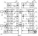
Фиг.2 - транспортер опускания и извлечения нагревательного кабеля из скважины;Figure 2 - conveyor lowering and removing the heating cable from the well;
Фиг.3 - пара роликов с пропущенным между ними нагревательным кабелем;Figure 3 - a pair of rollers with a heating cable passed between them;
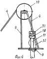
Фиг.4 - противовыбросовое крепление нагревательного кабеля на устье скважины.Figure 4 - blowout fastening of the heating cable at the wellhead.
На опоре 1 (фиг.1), которая вмонтирована в бетонном фундаменте, размещено крепежное устройство 2 с натяжным роликом 3, через который пропущен нагревательный кабель (далее кабель) 4. Один конец кабеля 4 подключен к соединительной коробке 5, к которой, с другой стороны, подведен и подключен силовой кабель 6. Другой конец силового кабеля 6 введен в систему управления нагревом кабеля 4, выполненную, например, в виде автоматизированного регулируемого источника электропитания (АРИЭ) 7, к которому подведена силовая линия (на фиг.1 не показана) напряжением 380 В.On the support 1 (Fig. 1), which is mounted in a concrete foundation, a mounting device 2 with a tension roller 3 is placed, through which a heating cable (hereinafter cable) is passed 4. One end of the
На бетонной площадке располагается устьевое оборудование: на верхнем, горизонтально расположенном фланце 8 которого установлен роликовый блок 9 с направляющим роликом 10. Через ролик 10 и устьевой сальник 11 типа СУСГ кабель 4 опускается в насосно-компрессорную трубу 12. При этом на фланце 13 крепежного устройства 14 закреплен транспортер 15 (фиг.2) с приводными механизмами 16 и 17 и регулировочным винтом 18. На верхней части насосно-компрессорной трубы 12 установлен сальник 11 с затяжной муфтой 19. На насосно-компрессорной трубе 12, на устье скважины размещен главный превентор 20 и имеется отвод 21 нефти к трубопроводу (на фиг. не показан).Wellhead equipment is located on the concrete site: on the upper horizontally located
Транспортер 15 (фиг.2) кабеля 4 содержит разъемный корпус, в котором размещены попарно взаимодействующие ролики 22i... 22n одной группы и ролики 23i... 23n другой группы для пропускания между ними кабеля 4, и шестерни 24i... 24n и 25i... 25n, установленные на осях соответствующих роликов 22i... 22n и 23i... 23n. Одна группа роликов 22i... 22n подсоединена к приводному механизму 16, а другая группа роликов 23i... 23n - к приводному механизму 17, причем ролики разбиты на группы поочередно.The conveyor 15 (figure 2) of
Корпус транспортера 15 выполнен разъемным и состоит из двух частей 26 и 27, которые соединяются, например, с помощью шарниров 28, при этом часть корпуса 26 является приводной. Причем, например, в части 26 размещены поочередно установленные ролики 22i, 223... 22n-1 с рабочими шестернями 24i, 24з... 24n-1 одной группы и ролики 23i, 23з... 23n-1 с рабочими шестернями 25i, 25з... 25n-1, другой группы, причем шестерни 24i, 24з... 24n-1 и шестерни 25i, 25з... 25n-1 установлены с возможностью взаимодействия с паразитными шестернями 29. В другой части корпуса 27 размещены ролики 222, 224... 22n одной группы и ролики 232, 234... 23n другой группы, каждый из которых составляет пару с соответствующим роликом 22i, 223... 22n-1 или 231, 233... 23n-1 данной группы.The housing of the
Кроме того, корпус снабжен стягивающим элементом 30, который, стягивая части 26 и 27 корпуса, регулирует мощность работы транспортера 15.In addition, the housing is equipped with a tightening
После завершения спуска кабеля 4 в скважину на всю его длину, и демонтажа транспортера 15, на кабель 4 над устьевым сальником 11 устанавливают страховочные хомуты 31 и противовыбросовый трос 32, который закрепляется к фонтанной арматуре.After completing the descent of the
Предлагаемая установка для депарафинизации нефтедобывающих скважин работает следующим образом.The proposed installation for dewaxing oil wells works as follows.
На верхний фланец 8 устьевого оборудования устанавливается блок 9 направляющего ролика 10, а на верхнюю часть насосно-компрессорной трубы 12 навинчивается устьевой сальник 11, над затяжной муфтой 19 которого устанавливается крепежное устройство 14 транспортера 15 нагревательного кабеля 4 с фланцем 13.A
При проведении всех этих операций во избежание попадания нефти под давлением в верхнюю устьевую часть скважины, перекрывают главный превентор 20. Следует отметить, что транспортер 15 устанавливают на устье скважины при наличии давления долее 10 атм. Перекрыв главный превентор 20, пропускают конец кабеля 4 с лебедки каротажной установки под натяжным роликом 3, через направляющий ролик 10 и устьевой сальник 11 внутрь насосно-компрессорной трубы 12 и опускают кабель до перекрытого превентора 20. Затем зажимают уплотнение устьевого сальника 11 затяжной муфтой 19 и устанавливают транспортер, надев его на кабель 4. После этого закрывают корпус транспортера 15, пропустив кабель 4 между парами роликов 22i... 22n и 23i... 23n, стягивают части 26 и 27 корпуса транспортера 15 регулировочным стягивающим элементом 30, создавая при этом такое усилие прижатия роликов к кабелю 4, которое обеспечивало бы достаточное трение между роликами и кабелем для передачи необходимого усилия (мощности), противодействующего выталкивающей силе, действующей на кабель 4 из скважины устьевым давлением, при опускании кабеля 4 в скважину, предварительно открыв превентор 20. После этого включают электрические или пневматические приводные механизмы 16 и 17 транспортера 15.During all these operations, in order to prevent oil under pressure from entering the upper wellhead, the main preventer 20 is shut off. It should be noted that the
Опускание кабеля 4 с помощью транспортера 15 осуществляют на глубину, при которой вес спущенного в скважину кабеля 4 станет равным выталкивающей силе давления из скважины. Далее кабель 4 будет опускаться в скважину под собственным весом.Lowering the
После спуска кабеля 4 на заданную глубину зоны возможного парафинообразования, второй конец кабеля 4, освободив его от лебедки каротажной станции, подключают электрически к силовому кабелю 6 через соединительную коробку 5. Затем в АРИЭ 7 в ручном режиме устанавливают расчетную величину температуры нагрева кабеля 4, гистерезис (выбранную температуру остывания кабеля 4), и временной режим цикличной работы (интервал времени работы). Регулирует режим работы нагрева кабеля 4 таким образом, чтобы температура по всей его длине в скважине по меньшей мере 3-4 часа в сутки была на 5-50° С выше температуры плавления парафина.After lowering the
Причем при подъеме кабеля 4 приводные механизмы 16 и 17 подсоединены к транспортеру 15 так, что обеспечивается заданная скорость и необходимое усилие для равномерного движения нагревательного кабеля 4, оставшегося в скважине, компенсируя выталкивающую силу устьевого давления, работой транспортера.Moreover, when lifting the
Claims (2)
Translated fromRussianPriority Applications (1)
| Application Number | Priority Date | Filing Date | Title |
|---|---|---|---|
| RU2002118239/03ARU2246606C2 (en) | 2002-07-09 | 2002-07-09 | Device for dewaxing oil-extractive wells |
Applications Claiming Priority (1)
| Application Number | Priority Date | Filing Date | Title |
|---|---|---|---|
| RU2002118239/03ARU2246606C2 (en) | 2002-07-09 | 2002-07-09 | Device for dewaxing oil-extractive wells |
Publications (2)
| Publication Number | Publication Date |
|---|---|
| RU2002118239A RU2002118239A (en) | 2004-01-20 |
| RU2246606C2true RU2246606C2 (en) | 2005-02-20 |
Family
ID=35218964
Family Applications (1)
| Application Number | Title | Priority Date | Filing Date |
|---|---|---|---|
| RU2002118239/03ARU2246606C2 (en) | 2002-07-09 | 2002-07-09 | Device for dewaxing oil-extractive wells |
Country Status (1)
| Country | Link |
|---|---|
| RU (1) | RU2246606C2 (en) |
Citations (8)
| Publication number | Priority date | Publication date | Assignee | Title |
|---|---|---|---|---|
| US4673035A (en)* | 1986-01-06 | 1987-06-16 | Gipson Thomas C | Method and apparatus for injection of tubing into wells |
| EP0242256A1 (en)* | 1986-04-04 | 1987-10-21 | Institut Français du Pétrole | Process and device for measuring characteristics of geological formations in a horizontal borehole coming from an underground tunnel |
| EP0256601A1 (en)* | 1986-08-13 | 1988-02-24 | Nik Smet | Method and device for making a hole in the ground |
| US4921217A (en)* | 1982-10-31 | 1990-05-01 | Erico International Corporation | Ground rods and apparatus for forming and placing such rods |
| US5556764A (en)* | 1993-02-17 | 1996-09-17 | Biometric Imaging, Inc. | Method and apparatus for cell counting and cell classification |
| US5803168A (en)* | 1995-07-07 | 1998-09-08 | Halliburton Company | Tubing injector apparatus with tubing guide strips |
| EP1036915A1 (en)* | 1999-03-15 | 2000-09-20 | Institut Francais Du Petrole | Method and device for controlling the deformation of an unrolled metal pipe |
| RU2166615C1 (en)* | 1999-10-11 | 2001-05-10 | Самгин Юрий Сергеевич | Process of dewaxing of oil and gas wells and plant for its realization |
- 2002
- 2002-07-09RURU2002118239/03Apatent/RU2246606C2/ennot_activeIP Right Cessation
Patent Citations (9)
| Publication number | Priority date | Publication date | Assignee | Title |
|---|---|---|---|---|
| US4921217A (en)* | 1982-10-31 | 1990-05-01 | Erico International Corporation | Ground rods and apparatus for forming and placing such rods |
| US4673035A (en)* | 1986-01-06 | 1987-06-16 | Gipson Thomas C | Method and apparatus for injection of tubing into wells |
| US4673035B1 (en)* | 1986-01-06 | 1999-08-10 | Plains Energy Services Ltd | Method and apparatus for injection of tubing into wells |
| EP0242256A1 (en)* | 1986-04-04 | 1987-10-21 | Institut Français du Pétrole | Process and device for measuring characteristics of geological formations in a horizontal borehole coming from an underground tunnel |
| EP0256601A1 (en)* | 1986-08-13 | 1988-02-24 | Nik Smet | Method and device for making a hole in the ground |
| US5556764A (en)* | 1993-02-17 | 1996-09-17 | Biometric Imaging, Inc. | Method and apparatus for cell counting and cell classification |
| US5803168A (en)* | 1995-07-07 | 1998-09-08 | Halliburton Company | Tubing injector apparatus with tubing guide strips |
| EP1036915A1 (en)* | 1999-03-15 | 2000-09-20 | Institut Francais Du Petrole | Method and device for controlling the deformation of an unrolled metal pipe |
| RU2166615C1 (en)* | 1999-10-11 | 2001-05-10 | Самгин Юрий Сергеевич | Process of dewaxing of oil and gas wells and plant for its realization |
Also Published As
| Publication number | Publication date |
|---|---|
| RU2002118239A (en) | 2004-01-20 |
Similar Documents
| Publication | Publication Date | Title |
|---|---|---|
| USRE45331E1 (en) | Top feed of control lines to table-elevated spider | |
| US20130098632A1 (en) | Gradational insertion of an artificial lift system into a live wellbore | |
| EP0257744B1 (en) | Drilling system | |
| CA1225021A (en) | Wireline apparatus | |
| US7198118B2 (en) | Communication adapter for use with a drilling component | |
| US6530433B2 (en) | Wellhead with ESP cable pack-off for low pressure applications | |
| RU2509203C2 (en) | Draw work for manoeuvring of drilling devices | |
| US20030155127A1 (en) | Intervention device for a subsea well, and method and cable for use with the device | |
| US10837252B2 (en) | Containment systems for sealing a pass-through in a well, and methods therefore | |
| US11952855B2 (en) | Containment systems for sealing a pass-through in a well, and methods therefore | |
| US4515211A (en) | Tool cable feeding system | |
| EA007085B1 (en) | Method for de-waxing gas and oil wells and corresponding installation | |
| MY158806A (en) | System and method for installing a subsea pipeline | |
| WO2010151176A2 (en) | Method and device for eliminating paraffin deposits and hydrate plugs in oil and gas wells | |
| RU2246606C2 (en) | Device for dewaxing oil-extractive wells | |
| RU97119587A (en) | METHOD FOR PREVENTING EDUCATION AND ELIMINATION OF PARAFFIN TUBES IN OIL AND GAS WELLS AND A DEVICE FOR ITS IMPLEMENTATION | |
| RU2317401C1 (en) | Downhole heater | |
| CN113006717A (en) | Marine underwater coiled tubing device and method | |
| WO2021011291A1 (en) | Self-contained well intervention system and method | |
| RU2167008C1 (en) | Method of cleaning oil-and-gas pipe lines from wax accumulation and livers and device its embodiment | |
| RU2738875C1 (en) | Method of electric centrifugal pump installation on load carrying cable (versions) | |
| SU1499049A1 (en) | Device for shutting-off a pipline | |
| RU2029853C1 (en) | Method to descend geophysical instrumentation into a well with excessive pressure | |
| US4649778A (en) | Pipe spinner assembly | |
| SU1709067A1 (en) | Wellhead blowout elimination outfit |
Legal Events
| Date | Code | Title | Description |
|---|---|---|---|
| PD4A | Correction of name of patent owner | ||
| MM4A | The patent is invalid due to non-payment of fees | Effective date:20070710 | |
| MM4A | The patent is invalid due to non-payment of fees | Effective date:20090710 |