RU2240203C2 - Casting core for investment pattern casting (variants), casting core - shell mold assembly, casting mold and casting produced with use of such core - Google Patents
Casting core for investment pattern casting (variants), casting core - shell mold assembly, casting mold and casting produced with use of such coreDownload PDFInfo
- Publication number
- RU2240203C2 RU2240203C2RU2002128179/02ARU2002128179ARU2240203C2RU 2240203 C2RU2240203 C2RU 2240203C2RU 2002128179/02 ARU2002128179/02 ARU 2002128179/02ARU 2002128179 ARU2002128179 ARU 2002128179ARU 2240203 C2RU2240203 C2RU 2240203C2
- Authority
- RU
- Russia
- Prior art keywords
- casting
- component
- refractory metal
- core
- ceramic
- Prior art date
Links
- 238000005266castingMethods0.000titleclaimsabstractdescription98
- 239000011258core-shell materialSubstances0.000title1
- 239000000919ceramicSubstances0.000claimsabstractdescription56
- 239000003870refractory metalSubstances0.000claimsabstractdescription43
- 239000002131composite materialSubstances0.000claimsabstractdescription18
- 229910000601superalloyInorganic materials0.000claimsabstractdescription18
- 239000000126substanceSubstances0.000claimsabstractdescription6
- 238000005495investment castingMethods0.000claimsdescription12
- 238000000034methodMethods0.000claimsdescription11
- 230000003647oxidationEffects0.000claimsdescription5
- 238000007254oxidation reactionMethods0.000claimsdescription5
- 239000011241protective layerSubstances0.000claimsdescription2
- 239000000155meltSubstances0.000claims1
- 238000004519manufacturing processMethods0.000abstractdescription9
- 230000000694effectsEffects0.000abstractdescription3
- 238000010420art techniqueMethods0.000abstract1
- 230000002708enhancing effectEffects0.000abstract1
- 239000000306componentSubstances0.000description47
- 238000001816coolingMethods0.000description20
- 229910052751metalInorganic materials0.000description14
- 239000002184metalSubstances0.000description14
- VYPSYNLAJGMNEJ-UHFFFAOYSA-NSilicium dioxideChemical compoundO=[Si]=OVYPSYNLAJGMNEJ-UHFFFAOYSA-N0.000description9
- 239000000463materialSubstances0.000description6
- 229910045601alloyInorganic materials0.000description5
- 239000000956alloySubstances0.000description5
- PNEYBMLMFCGWSK-UHFFFAOYSA-Naluminium oxideInorganic materials[O-2].[O-2].[O-2].[Al+3].[Al+3]PNEYBMLMFCGWSK-UHFFFAOYSA-N0.000description5
- 229910052750molybdenumInorganic materials0.000description5
- PXHVJJICTQNCMI-UHFFFAOYSA-NNickelChemical compound[Ni]PXHVJJICTQNCMI-UHFFFAOYSA-N0.000description4
- 239000010410layerSubstances0.000description4
- 150000002739metalsChemical class0.000description4
- 239000000377silicon dioxideSubstances0.000description4
- 239000003518causticsSubstances0.000description3
- 238000000576coating methodMethods0.000description3
- 238000002485combustion reactionMethods0.000description3
- 238000005516engineering processMethods0.000description3
- 210000003746featherAnatomy0.000description3
- 229910000765intermetallicInorganic materials0.000description3
- 229910052758niobiumInorganic materials0.000description3
- 239000010955niobiumSubstances0.000description3
- 239000002245particleSubstances0.000description3
- 239000000243solutionSubstances0.000description3
- 229910052715tantalumInorganic materials0.000description3
- 229910052721tungstenInorganic materials0.000description3
- 229910001182Mo alloyInorganic materials0.000description2
- ZOKXTWBITQBERF-UHFFFAOYSA-NMolybdenumChemical compound[Mo]ZOKXTWBITQBERF-UHFFFAOYSA-N0.000description2
- 238000005452bendingMethods0.000description2
- 238000005524ceramic coatingMethods0.000description2
- 229910010293ceramic materialInorganic materials0.000description2
- 239000011651chromiumSubstances0.000description2
- 239000011247coating layerSubstances0.000description2
- 239000008358core componentSubstances0.000description2
- KZHJGOXRZJKJNY-UHFFFAOYSA-Ndioxosilane;oxo(oxoalumanyloxy)alumaneChemical compoundO=[Si]=O.O=[Si]=O.O=[Al]O[Al]=O.O=[Al]O[Al]=O.O=[Al]O[Al]=OKZHJGOXRZJKJNY-UHFFFAOYSA-N0.000description2
- 230000003628erosive effectEffects0.000description2
- 238000001746injection mouldingMethods0.000description2
- 238000012986modificationMethods0.000description2
- 230000004048modificationEffects0.000description2
- 239000011733molybdenumSubstances0.000description2
- 229910052863mulliteInorganic materials0.000description2
- 229910052759nickelInorganic materials0.000description2
- 239000000725suspensionSubstances0.000description2
- 238000003466weldingMethods0.000description2
- 238000004804windingMethods0.000description2
- 229910052726zirconiumInorganic materials0.000description2
- VYZAMTAEIAYCRO-UHFFFAOYSA-NChromiumChemical compound[Cr]VYZAMTAEIAYCRO-UHFFFAOYSA-N0.000description1
- 229910016006MoSiInorganic materials0.000description1
- 229910004298SiO 2Inorganic materials0.000description1
- XSQUKJJJFZCRTK-UHFFFAOYSA-NUreaChemical compoundNC(N)=OXSQUKJJJFZCRTK-UHFFFAOYSA-N0.000description1
- 229910001080W alloyInorganic materials0.000description1
- QCWXUUIWCKQGHC-UHFFFAOYSA-NZirconiumChemical compound[Zr]QCWXUUIWCKQGHC-UHFFFAOYSA-N0.000description1
- 238000010306acid treatmentMethods0.000description1
- 230000001464adherent effectEffects0.000description1
- 239000011230binding agentSubstances0.000description1
- 230000015572biosynthetic processEffects0.000description1
- 239000004202carbamideSubstances0.000description1
- 230000001413cellular effectEffects0.000description1
- 238000006243chemical reactionMethods0.000description1
- 238000005229chemical vapour depositionMethods0.000description1
- 229910052804chromiumInorganic materials0.000description1
- 239000011248coating agentSubstances0.000description1
- 239000008119colloidal silicaSubstances0.000description1
- 238000005336crackingMethods0.000description1
- 238000005520cutting processMethods0.000description1
- 125000004122cyclic groupChemical group0.000description1
- 230000006378damageEffects0.000description1
- 230000007547defectEffects0.000description1
- 238000009792diffusion processMethods0.000description1
- 239000006185dispersionSubstances0.000description1
- 238000001962electrophoresisMethods0.000description1
- 239000012634fragmentSubstances0.000description1
- 239000000446fuelSubstances0.000description1
- WIHZLLGSGQNAGK-UHFFFAOYSA-Nhafnium(4+);oxygen(2-)Chemical class[O-2].[O-2].[Hf+4]WIHZLLGSGQNAGK-UHFFFAOYSA-N0.000description1
- 238000007654immersionMethods0.000description1
- 238000002347injectionMethods0.000description1
- 239000007924injectionSubstances0.000description1
- 238000003698laser cuttingMethods0.000description1
- 238000002844meltingMethods0.000description1
- 230000008018meltingEffects0.000description1
- 229910001092metal group alloyInorganic materials0.000description1
- 239000000203mixtureSubstances0.000description1
- 239000012768molten materialSubstances0.000description1
- MGRWKWACZDFZJT-UHFFFAOYSA-Nmolybdenum tungstenChemical compound[Mo].[W]MGRWKWACZDFZJT-UHFFFAOYSA-N0.000description1
- 238000000465mouldingMethods0.000description1
- GUCVJGMIXFAOAE-UHFFFAOYSA-Nniobium atomChemical compound[Nb]GUCVJGMIXFAOAE-UHFFFAOYSA-N0.000description1
- 229910000510noble metalInorganic materials0.000description1
- 150000002894organic compoundsChemical class0.000description1
- RVTZCBVAJQQJTK-UHFFFAOYSA-Noxygen(2-);zirconium(4+)Chemical compound[O-2].[O-2].[Zr+4]RVTZCBVAJQQJTK-UHFFFAOYSA-N0.000description1
- 238000001259photo etchingMethods0.000description1
- 238000005240physical vapour depositionMethods0.000description1
- 239000004033plasticSubstances0.000description1
- 229920003023plasticPolymers0.000description1
- 239000011253protective coatingSubstances0.000description1
- 230000001681protective effectEffects0.000description1
- 229910000753refractory alloyInorganic materials0.000description1
- 239000011214refractory ceramicSubstances0.000description1
- 239000011819refractory materialSubstances0.000description1
- 229910052702rheniumInorganic materials0.000description1
- 238000007789sealingMethods0.000description1
- 230000035939shockEffects0.000description1
- 150000004760silicatesChemical class0.000description1
- 239000002002slurrySubstances0.000description1
- 238000005476solderingMethods0.000description1
- 239000007787solidSubstances0.000description1
- 239000006104solid solutionSubstances0.000description1
- GUVRBAGPIYLISA-UHFFFAOYSA-Ntantalum atomChemical compound[Ta]GUVRBAGPIYLISA-UHFFFAOYSA-N0.000description1
- WFKWXMTUELFFGS-UHFFFAOYSA-NtungstenChemical compound[W]WFKWXMTUELFFGS-UHFFFAOYSA-N0.000description1
- 239000010937tungstenSubstances0.000description1
- 229910001928zirconium oxideInorganic materials0.000description1
Images


Classifications
- B—PERFORMING OPERATIONS; TRANSPORTING
- B22—CASTING; POWDER METALLURGY
- B22D—CASTING OF METALS; CASTING OF OTHER SUBSTANCES BY THE SAME PROCESSES OR DEVICES
- B22D29/00—Removing castings from moulds, not restricted to casting processes covered by a single main group; Removing cores; Handling ingots
- B22D29/001—Removing cores
- B22D29/002—Removing cores by leaching, washing or dissolving
- B—PERFORMING OPERATIONS; TRANSPORTING
- B22—CASTING; POWDER METALLURGY
- B22C—FOUNDRY MOULDING
- B22C9/00—Moulds or cores; Moulding processes
- B22C9/10—Cores; Manufacture or installation of cores
- B—PERFORMING OPERATIONS; TRANSPORTING
- B22—CASTING; POWDER METALLURGY
- B22C—FOUNDRY MOULDING
- B22C21/00—Flasks; Accessories therefor
- B22C21/12—Accessories
- B22C21/14—Accessories for reinforcing or securing moulding materials or cores, e.g. gaggers, chaplets, pins, bars
- B—PERFORMING OPERATIONS; TRANSPORTING
- B22—CASTING; POWDER METALLURGY
- B22C—FOUNDRY MOULDING
- B22C9/00—Moulds or cores; Moulding processes
- B22C9/02—Sand moulds or like moulds for shaped castings
- B22C9/04—Use of lost patterns
- B—PERFORMING OPERATIONS; TRANSPORTING
- B22—CASTING; POWDER METALLURGY
- B22C—FOUNDRY MOULDING
- B22C9/00—Moulds or cores; Moulding processes
- B22C9/10—Cores; Manufacture or installation of cores
- B22C9/103—Multipart cores
- F—MECHANICAL ENGINEERING; LIGHTING; HEATING; WEAPONS; BLASTING
- F01—MACHINES OR ENGINES IN GENERAL; ENGINE PLANTS IN GENERAL; STEAM ENGINES
- F01D—NON-POSITIVE DISPLACEMENT MACHINES OR ENGINES, e.g. STEAM TURBINES
- F01D5/00—Blades; Blade-carrying members; Heating, heat-insulating, cooling or antivibration means on the blades or the members
- F01D5/12—Blades
- F01D5/14—Form or construction
- F01D5/18—Hollow blades, i.e. blades with cooling or heating channels or cavities; Heating, heat-insulating or cooling means on blades
- F01D5/187—Convection cooling
- F—MECHANICAL ENGINEERING; LIGHTING; HEATING; WEAPONS; BLASTING
- F05—INDEXING SCHEMES RELATING TO ENGINES OR PUMPS IN VARIOUS SUBCLASSES OF CLASSES F01-F04
- F05D—INDEXING SCHEME FOR ASPECTS RELATING TO NON-POSITIVE-DISPLACEMENT MACHINES OR ENGINES, GAS-TURBINES OR JET-PROPULSION PLANTS
- F05D2230/00—Manufacture
- F05D2230/20—Manufacture essentially without removing material
- F05D2230/21—Manufacture essentially without removing material by casting
- F05D2230/211—Manufacture essentially without removing material by casting by precision casting, e.g. microfusing or investment casting
- Y—GENERAL TAGGING OF NEW TECHNOLOGICAL DEVELOPMENTS; GENERAL TAGGING OF CROSS-SECTIONAL TECHNOLOGIES SPANNING OVER SEVERAL SECTIONS OF THE IPC; TECHNICAL SUBJECTS COVERED BY FORMER USPC CROSS-REFERENCE ART COLLECTIONS [XRACs] AND DIGESTS
- Y02—TECHNOLOGIES OR APPLICATIONS FOR MITIGATION OR ADAPTATION AGAINST CLIMATE CHANGE
- Y02T—CLIMATE CHANGE MITIGATION TECHNOLOGIES RELATED TO TRANSPORTATION
- Y02T50/00—Aeronautics or air transport
- Y02T50/60—Efficient propulsion technologies, e.g. for aircraft
Landscapes
- Engineering & Computer Science (AREA)
- Mechanical Engineering (AREA)
- General Engineering & Computer Science (AREA)
- Molds, Cores, And Manufacturing Methods Thereof (AREA)
- Turbine Rotor Nozzle Sealing (AREA)
Abstract
Description
Translated fromRussianОбласть техники, к которой относится изобретениеFIELD OF THE INVENTION
Настоящее изобретение относится к литейным стержням, используемым для литья по выплавляемым моделям, и, в частности, к стержням такого рода, по меньшей мере, частично сформированным из тугоплавких металлов.The present invention relates to casting cores used for investment casting, and, in particular, to cores of this kind, at least partially formed from refractory metals.
Уровень техникиState of the art
Литье по выплавляемым моделям представляет собой технологию, применяемую обычно для формирования металлических компонентов сложной конфигурации и, в особенности, компонентов, имеющих полости. Такое литье используют при получении изготовленных из суперсплавов компонентов газотурбинных двигателей. Хотя изобретение будет описано применительно к производству отливок из суперсплавов, следует иметь в виду, что оно не ограничено этими рамками.Lost wax casting is a technology commonly used to form metal components of complex configuration and, in particular, components having cavities. Such casting is used in the production of components of gas turbine engines made from superalloys. Although the invention will be described in relation to the production of castings from superalloys, it should be borne in mind that it is not limited to these frameworks.
Газотурбинные двигатели широко применяют в силовых установках самолетов и судов, а также для выработки электрической энергии. Во всех приложениях этих двигателей первостепенной решаемой задачей является коэффициент полезного действия.Gas turbine engines are widely used in power plants of aircraft and ships, as well as for the generation of electrical energy. In all applications of these engines, the primary task to be solved is the efficiency.
Улучшить этот параметр можно посредством работы при повышенных температурах, однако применяемые в настоящее время рабочие температуры находятся на уровне, ограничивающем механические свойства материалов из суперсплавов, использующихся в турбинной секции. Поэтому в наиболее горячих узлах газотурбинных двигателей, обычно в турбинной секции, широко практикуют обеспечение компонентов воздушным охлаждением. Охлаждение обеспечивают за счет протекания относительно холодного воздуха из компрессорной секции двигателя через каналы, полости и отверстия (далее называемые в совокупности внутренними полыми элементами) в компонентах турбины, подлежащих охлаждению. Следует иметь в виду, что охлаждение вместе со связанными с ним затратами учитывается в коэффициенте полезного действия двигателя. Поэтому важной задачей является обеспечение качественного специфического охлаждения с максимальной его эффективностью для данного количества охлаждающего воздуха.This parameter can be improved by working at elevated temperatures, however, the currently used operating temperatures are at a level that limits the mechanical properties of materials from superalloys used in the turbine section. Therefore, in the hottest components of gas turbine engines, usually in the turbine section, it is widely practiced to provide components with air cooling. Cooling is ensured by the flow of relatively cold air from the compressor section of the engine through the channels, cavities and openings (hereinafter referred to collectively as internal hollow elements) in the turbine components to be cooled. It should be borne in mind that cooling, together with the associated costs, is taken into account in the efficiency of the engine. Therefore, an important task is to ensure high-quality specific cooling with its maximum efficiency for a given amount of cooling air.
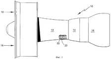
Как видно из фиг.1, газотурбинный двигатель 10 включает в себя компрессор 12, камеру 14 сгорания и турбину 16. Через секции 12, 14 и 16 двигателя 10, вдоль их оси протекает воздух 18. Как хорошо известно специалистам в этой области, воздух 18, сжатый в компрессоре 12, смешивается с топливом, сжигаемым в камере 14 сгорания, после чего газовый поток поступает в турбину 16, тем самым вращая ее и приводя в действие компрессор 12.As can be seen from figure 1, the
Как компрессор 12, так и турбина 16 содержат вращающиеся и стационарные лопатки (соответственно 20, 22). Эти лопатки, особенно те из них, которые расположены в турбине 16, подвергаются повторяющемуся циклическому воздействию в широком интервале температур и давлений. Чтобы избежать термического разрушения лопаток 20, каждая из них включает в себя внутреннее охлаждение.Both
Как видно из фиг.2, лопатка 20 включает в себя перо, имеющее входную кромку 26 и выходную кромку 28, которые занимают пространство от верхнего края корневой части 30 лопатки до наружного края 32 пера, и полку 34. Контур 40 охлаждения входной кромки сформирован радиально проходящими внутри входной кромки 26 пера лопатки 20 соединенными каналами 42-44 и впускным отверстием 46, выполненным в полке 34 со стороны входной кромки и сопряженным с каналом 42. Множество поперечных отверстий 48, сформированных в зоне входной кромки, т.е. в стенке 50, которая отделяет канал 44 от выпускной полости (полого элемента) 52 входной кромки, позволяет охлаждающему воздуху перетекать из канала 44 в указанную выпускную полость 52. Контур 56 охлаждения выходной кромки сформирован радиально проходящими внутри выходной кромки 28 пера лопатки 20 соединенными каналами 58-60 и впускным отверстием 62, выполненным в полке 34 со стороны выходной кромки пера лопатки и сопряженным с каналом 58. Чтобы обеспечить перетекание охлаждающего воздуха из канала 58 через промежуточную полость (полый элемент) 78 к множеству выпускных отверстий 80 выходной кромки, в ее первой и второй стенках (соответственно 68 и 74) сформированы первое и второе множество поперечных отверстий (соответственно 66 и 72).As can be seen from figure 2, the
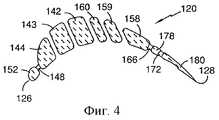
В процессе изготовления лопаток традиционно используют керамический литейный стержень (см., например, документ US 4384607, B 29 D 29/00, 24.05.1983). Как показано на фиг.3 и 4, такой керамический литейный стержень 120 формирует в лопатке 20 требуемые полости. Входная и выходная кромки (соответственно 126 и 128) такого стержня соотносятся с аналогичными кромками (соответственно 26 и 28) пера лопатки 20. Корневая часть 130 и наружный край 132 стержня соотносятся с аналогичными компонентами (соответственно 30 и 32) лопатки. Его контурам 140, 156 с каналами 142-144, 158-160 и соответственно впускными отверстиями 146, 162 отвечают у лопатки соответственно контуры 40, 56 охлаждения с каналами 42-44, 58-60 и впускными отверстиями 46, 62. Полости 52 и 78 в пере лопатки соотносятся с каналами 152 и 178 в керамическом литейном стержне. Множество выступов 148, 166, 172 в литейном стержне 120 отвечает множеству поперечных отверстий, соответственно 48, 66, 72 в лопатке 20. Чтобы стабилизировать указанный стержень у наружного края 132, оконечность 190 стержня присоединена к его контурам 140, 156 посредством перемычек 182-185. Для целей манипулирования (перемещения) к выходной кромке 128 литейного стержня присоединена наружная керамическая рукоятка 194. Расширяющийся участок 196 стержня обеспечивает формирование канала контура охлаждения в хвостовике (корневой части) до пера лопатки 20. Средние линии 197-199 проходят в радиальном направлении через каждый ряд выступов 148, 166, 172 соответственно.In the manufacturing process of the blades, a ceramic foundry core is traditionally used (see, for example, document US 4384607, B 29 D 29/00, 05.24.1983). As shown in FIGS. 3 and 4, such a
Хотя с точки зрения охлаждения вращающиеся и неподвижные турбинные лопатки относятся к числу наиболее важных компонентов, охлаждения требуют также и другие компоненты, такие как камеры сгорания и наружные герметизирующие уплотнения лопаток. Изобретение применимо ко всем охлаждаемым металлическим узлам турбины и фактически ко всем сложным литым изделиям.Although in terms of cooling, rotating and stationary turbine blades are among the most important components, other components, such as combustion chambers and external sealing blades seals, also require cooling. The invention is applicable to all cooled metallic components of a turbine and to virtually all complex molded products.
В настоящее время литейные стержни показанного на фиг.3, 4 типа изготавливают из керамических материалов. Однако известные керамические стержни имеют хрупкую природу. В особенности это касается современных стержней, применяющихся для формирования мелких охлаждающих каналов в металлическом узле. Для этих керамических литейных стержней наблюдается тенденция к искривлению и перелому во время изготовления и процесса получения отливки. Для некоторых конструкций современных экспериментальных лопаток значения выхода при литье составляют менее 10%, причем главным образом из-за дефектов литейного стержня.Currently, casting cores shown in figure 3, 4 types are made of ceramic materials. However, the known ceramic rods are brittle in nature. This is especially true of modern rods used to form small cooling channels in a metal assembly. For these ceramic foundry cores, there is a tendency to curvature and fracture during manufacturing and the casting process. For some designs of modern experimental blades, the casting yield is less than 10%, and mainly due to defects in the casting core.
Обычные керамические литейные стержни производят методом литья, используя керамическую суспензию и профильную пресс-форму. Можно использовать технические приемы как литья под давлением, так и литьевого прессования. Наиболее распространенным материалом моделей является воск (см., например, патент США №5387280), хотя находили применение также пластики, металлы с низкой точкой плавления и органические соединения, такие как мочевина. Оболочковую форму формируют, используя коллоидное кремнеземное связующее, предназначенное для связывания керамических частиц друг с другом. Такими частицами могут быть глинозем, кремнезем, оксид циркония и глиноземные силикаты.Conventional ceramic foundry cores are produced by casting using a ceramic slurry and a mold. You can use the techniques of both injection molding and injection molding. The most common model material is wax (see, for example, US Pat. No. 5,372,280), although plastics, low melting point metals, and organic compounds such as urea have also been used. The shell form is formed using a colloidal silica binder designed to bind ceramic particles to each other. Such particles may be alumina, silica, zirconium oxide and alumina silicates.
Далее будет приведено краткое описание процесса литья по выплавляемым моделям, использующего керамический литейный стержень и предназначенного для получения турбинной лопатки (см., например, документ ЕР 715913 А, В 22 С 9/10, 12.06.1996, где описаны литейный стержень, используемый при литье по выплавляемым моделям, литейная форма, отливка и отлитое изделие, которые являются ближайшими аналогами соответствующих изобретений, образующих предложенную группу изобретений). Литейный стержень, конфигурация которого соответствует внутренним каналам и другим полым элементам контура охлаждения отливки, помещают в металлическую пресс-форму, стенки которой окружают стержень, но обычно пространственно отделены от него. Пресс-форму заполняют легко удаляемым материалом модели, таким как воск. Удаляют пресс-форму, оставляя керамический стержень внедренным в восковую модель. После этого вокруг восковой модели формируют наружную оболочковую форму посредством погружения модели в керамическую суспензию, добавляя затем к суспензии более крупные сухие керамические частицы. Этот процесс известен под термином "обмазывание". Далее восковую модель с обмазкой, содержащую литейный стержень, высушивают и повторяют процесс обмазывания, чтобы обеспечить желаемую толщину стенки оболочковой формы. В этой точке технологической цепочки форму тщательно высушивают и нагревают до высокой температуры (прокаливают) с целью удаления воскового материала и упрочнения керамического материала.Next, a brief description will be given of the investment casting process using a ceramic casting core and designed to produce a turbine blade (see, for example, document EP 715913 A, B 22 C 9/10, 06/12/1996, which describes the casting rod used in Lost wax casting, casting mold, casting and molded product, which are the closest analogues of the respective inventions forming the proposed group of inventions). The foundry core, the configuration of which corresponds to the internal channels and other hollow elements of the cooling circuit of the casting, is placed in a metal mold, the walls of which surround the core, but are usually spatially separated from it. The mold is filled with easily removable model material such as wax. The mold is removed, leaving the ceramic core embedded in the wax model. After that, the outer shell form is formed around the wax model by immersing the model in a ceramic suspension, then adding larger, dry ceramic particles to the suspension. This process is known as coating. Next, the coated wax model containing the casting core is dried and the coating process is repeated to provide the desired wall thickness of the shell mold. At this point in the process chain, the mold is thoroughly dried and heated to a high temperature (calcined) in order to remove wax material and harden the ceramic material.
В результате получают керамическую форму-оболочку, содержащую керамический литейный стержень, который в указанной комбинации (сборке) определяет полость формы. Должно быть понятно, что наружная часть стержня и внутренняя часть оболочковой формы определяют, соответственно, полость, которая должна быть сформирована в процессе литья, а также наружные размеры отливки из суперсплавов, подлежащей изготовлению. Литейный стержень и оболочка могут определять также такие компоненты, как литниковые системы и выпоры, необходимые для процесса литья, но не являющиеся частью окончательного литого изделия.The result is a ceramic mold-shell containing a ceramic casting core, which in the indicated combination (assembly) defines the mold cavity. It should be understood that the outer part of the core and the inner part of the shell mold define, respectively, the cavity that must be formed during the casting process, as well as the external dimensions of the superalloy casting to be manufactured. Components such as gating systems and supports needed for the casting process, but not part of the final casting, can also determine the core and casing.
После удаления воска в полость, определенную сборкой оболочковой формы и литейного стержня, заливают расплавленный материал, состоящий из суперсплава, и дают ему возможность отвердиться (сборка литейного стержня и оболочковой формы, являющаяся ближайшим аналогом соответствующего изобретения, входящего в предложенную группу изобретений, описана в уже упоминавшемся документе US 4384607). Затем, комбинируя механические и химические средства, от отливки, состоящей из суперсплава, отделяют форму и стержень.After removing the wax, a molten material consisting of a superalloy is poured into the cavity defined by the assembly of the shell mold and the casting rod and it is allowed to solidify (the assembly of the casting rod and shell mold, which is the closest analogue of the corresponding invention included in the proposed group of inventions, is described in US Pat. No. 4,384,607 referred to). Then, combining mechanical and chemical means, the mold and the rod are separated from the casting consisting of superalloy.
Как было отмечено выше, применяемые обычно керамические литейные стержни вносят ограничения в конструкции отливок вследствие своей хрупкости и из-за того, что стержни такого рода, включающие в себя детали с размерами менее примерно 0,3-0,4 мм, как правило, невозможно производить с приемлемым выходом отлитых изделий.As noted above, commonly used ceramic foundry rods impose restrictions on the design of castings due to their fragility and due to the fact that rods of this kind, including parts with dimensions less than about 0.3-0.4 mm, are usually impossible produce with an acceptable yield of cast products.
Сущность изобретенияSUMMARY OF THE INVENTION
Таким образом, задачей, на решение которой направлено настоящее изобретение, является получение литейных стержней, предназначенных для литья по выплавляемым моделям и имеющих улучшенные механические свойства.Thus, the problem to which the present invention is directed, is to obtain casting cores intended for investment casting and having improved mechanical properties.
Другая задача, решаемая изобретением, сводится к получению литейных стержней, которые по сравнению с существующими керамическими стержнями такого рода можно изготовить с уменьшенной толщиной.Another problem solved by the invention is to obtain casting cores, which compared to existing ceramic cores of this kind can be made with a reduced thickness.
Следующая задача заключается в получении литейных стержней, устойчивых к термической ударной нагрузке во время литья.The next task is to obtain casting cores that are resistant to thermal shock during casting.
Еще одной задачей, решаемой изобретением, является получение литейных стержней, имеющих конфигурацию и характерные особенности, которые нельзя обеспечить в керамических литейных стержнях.Another objective solved by the invention is the production of foundry cores having a configuration and characteristic features that cannot be provided in ceramic foundry cores.
Еще одна задача изобретения сводится к получению литейных стержней, позволяющих быстро осуществлять сложные изменения конструкции, не прибегая к использованию дорогостоящих инструментов и процессов.Another objective of the invention is to obtain casting cores that allow you to quickly implement complex structural changes without resorting to the use of expensive tools and processes.
Для решения указанных выше задач и достижения других преимуществ в соответствии с настоящим изобретением предлагаются составные литейные стержни, содержащие, в дополнение к керамическому компоненту, также компонент или компоненты из тугоплавкого металла.To solve the above problems and to achieve other advantages, the present invention provides composite casting cores containing, in addition to the ceramic component, also a component or components of refractory metal.
Перечень таких металлов включает в себя молибден, тантал, ниобий, вольфрам и их сплавы. В рамках настоящего изобретения термин "тугоплавкие металлы" будет охватывать также интерметаллические соединения на основе перечисленных выше тугоплавких металлов. Согласно одному из вариантов осуществления изобретения для обеспечения улучшенных механических свойств в керамические литейные стержни вводят куски проволоки из тугоплавкого металла.The list of such metals includes molybdenum, tantalum, niobium, tungsten and their alloys. In the framework of the present invention, the term "refractory metals" will also cover intermetallic compounds based on the above refractory metals. According to one embodiment of the invention, pieces of wire made of refractory metal are introduced into ceramic casting cores to provide improved mechanical properties.
В соответствии с другим вариантом осуществления изобретения керамический литейный стержень можно сформировать вокруг полосы тугоплавкого материала, предварительно вырезав эту полосу и придав ей форму, согласованную, по меньшей мере, с участком требуемой конфигурации стержня.In accordance with another embodiment of the invention, a ceramic casting core can be formed around a strip of refractory material, having previously cut this strip and giving it a shape consistent with at least a portion of the desired configuration of the core.
Согласно следующему варианту осуществления изобретения тугоплавкая проволока или компонент из металлической полосы может сформировать часть литейного стержня и выдерживать воздействие расплавленного металла во время процесса литья.According to a further embodiment of the invention, a refractory wire or component from a metal strip can form part of the casting rod and withstand the effects of molten metal during the casting process.
В соответствии с вариантами осуществления изобретения компоненты литейного стержня, изготовленные из тугоплавкого металла, можно покрыть одним или несколькими слоями защитного материала, чтобы защитить тугоплавкие составляющие от взаимодействия с расплавленным металлом во время литья.In accordance with embodiments of the invention, casting core components made of refractory metal can be coated with one or more layers of protective material to protect the refractory components from interacting with molten metal during casting.
Согласно еще одному варианту осуществления изобретения литейные стержни для литья по выплавляемым моделям можно формировать из составных компонентов, изготовленных из керамики и тугоплавких металлов.According to another embodiment of the invention, casting casting cores can be formed from composite components made of ceramics and refractory metals.
Изобретение относится также: к литейной форме, снабженной описанным составным литейным стержнем; к сборке, состоящей из составного литейного стержня и оболочковой формы для изготовления отливки из суперсплава; к отливкам из суперсплава, изготовленным с использованием составного литейного стержня по изобретению.The invention also relates to: a casting mold provided with the described composite casting core; to an assembly consisting of a composite casting core and a shell mold for manufacturing a superalloy casting; superalloy castings made using the composite casting core of the invention.
Настоящее изобретение будет лучше понято из совместного рассмотрения прилагаемых чертежей и подробного описания.The present invention will be better understood from a joint consideration of the accompanying drawings and detailed description.
Перечень фигур чертежейList of drawings
Фиг.1 представляет собой упрощенное изображение (вид сбоку с вырывом) газотурбинного двигателя.Figure 1 is a simplified image (side view with a pullout) of a gas turbine engine.
Фиг.2 представляет собой в сечении увеличенное изображение (на виде сбоку) лопатки газотурбинного двигателя, показанного на фиг.1.Figure 2 is a sectional view of an enlarged image (side view) of the blades of the gas turbine engine shown in figure 1.
Фиг.3 представляет собой изображение (вид сбоку) керамического литейного стержня согласно настоящему изобретению, формирующего охлаждающие полости и каналы при изготовлении лопатки, показанной на фиг.2.FIG. 3 is a side view of a ceramic foundry core according to the present invention forming cooling cavities and channels in the manufacture of the blade shown in FIG. 2.
Фиг.4 представляет собой изображение керамического литейного стержня в сечении по стрелкам 4-4 на фиг.3.FIG. 4 is a sectional view of a ceramic foundry core in the direction of arrows 4–4 in FIG. 3.
Фиг.5 представляет изображение керамического литейного стержня в сечении по стрелкам 4-4, иллюстрирующее варианты осуществления изобретения.Figure 5 is a sectional view of a ceramic foundry core along arrows 4-4, illustrating embodiments of the invention.
Фиг.6 демонстрирует вариант механического соединения компонентов литейного стержня.6 shows a variant of the mechanical connection of the components of the casting core.
Фиг.7 демонстрирует деталь литейного стержня, изготовленную из тугоплавкого металла и предназначенную для формирования извилистого охлаждающего канала.7 shows a detail of a casting core made of refractory metal and intended to form a winding cooling channel.
Сведения, подтверждающие возможность осуществления изобретенияInformation confirming the possibility of carrying out the invention
Как было отмечено выше, применяемые обычно керамические литейные стержни, как правило, вносят ограничения в конструкцию современных сложных изделий из суперсплавов, налагая на схему литьевого устройства размерные ограничения. Фиг.5 иллюстрирует различные варианты осуществления настоящего изобретения. На этой фигуре, в сечении, показано изображение представленного на фиг.4 литейного стержня с различными компонентами из тугоплавких металлов, приведенными в качестве примеров.As noted above, commonly used ceramic foundry cores, as a rule, introduce restrictions on the design of modern complex products from superalloys, imposing dimensional restrictions on the scheme of the injection device. 5 illustrates various embodiments of the present invention. In this figure, in cross section, the image shown in figure 4 of the casting rod with various components of refractory metals, shown as examples.
В соответствии с фиг.5, демонстрирующей варианты осуществления изобретения, один или несколько кусков проволоки 200 из тугоплавких металлов можно ввести в керамический литейный стержень, чтобы обеспечить для него прочность и устойчивость по отношению к растрескиванию и искривлению. Хотя на фиг.5 показано круглое поперечное сечение проволоки, можно использовать и другие его формы.In accordance with FIG. 5, showing embodiments of the invention, one or more pieces of
Проволоку 202 можно локализовать также у поверхности керамики стержня 120 и сформировать контур его поверхности.The
Возможно применение также и компонентов в виде полос из тугоплавких металлов. Такие компоненты 204 можно расположить у поверхности компонента стержня. В другом варианте профильному компоненту 206 в виде тугоплавкой полосы можно придать конфигурацию, определяющую радиус и угол стержня. Подобным же образом компонент 208 из тугоплавкого металла может сформировать три стороны и два угла компонента керамического литейного стержня. Основную часть компонента 210, имеющего вид полосы из тугоплавкого металла, можно локализовать внутри компонента литейного стержня, расположив компонент 210 от одной поверхности до другой, а тугоплавкий компонент 212 такого же стержня можно локализовать полностью внутри компонента стержня.It is also possible to use components in the form of strips of refractory metals.
Выходную кромку 128, а также любой элемент литейного стержня 120 или несколько таких элементов можно полностью сформировать из полосы тугоплавкого металла, получив таким образом компонент стержня с приемлемыми свойствами, более тонкий по сравнению с компонентами, которые можно было бы изготовить из керамики.The
Компоненты литейного стержня или весь такой стержень можно также сконструировать из составных профильных полос 216 тугоплавких металлов, соединив эти полосы с помощью различных способов, включая контактную электросварку, дуговую сварку вольфрамовым электродом в среде инертного газа, пайку и соединение за счет диффузии.The components of the casting core or the entire such core can also be constructed from composite profile strips 216 of refractory metals by connecting these strips using various methods, including contact welding, TIG welding, soldering and diffusion bonding.
Описанные выше варианты осуществления изобретения имеют только иллюстративный характер. При конструировании литейного стержня можно применять любой из этих вариантов его выполнения или несколько таких вариантов, используя их в соответствии со спецификой конструкции стержня.The embodiments described above are for illustrative purposes only. When designing a foundry core, you can use any of these options for its implementation or several such options, using them in accordance with the specific design of the core.
На фиг.6 показано, как тонкий компонент выходной кромки литейного стержня, изготовленный из полосы тугоплавкого металла, можно применить при формировании участка цельного стержня, предназначенного для литья по выплавляемым моделям. Тонкий компонент 220 из тугоплавкого металла можно присоединить к керамическому фрагменту 222, снабдив указанный компонент выступающими наружу участками 224 или выемками 226. Соединение осуществляют инжектированием керамики в зону вокруг такого выступающего компонента и/или в выполненные в нем выемки, чтобы обеспечить механическое замыкание между керамическим компонентом и компонентом из тугоплавкого металла.Figure 6 shows how a thin component of the outlet edge of a casting rod made of a strip of refractory metal can be used to form a portion of a solid rod designed for investment casting. A
Фиг.7 иллюстрирует, каким образом компоненты 230 литейного стержня, изготовленные из тугоплавкого металла, можно применить для формирования в стенке пера лопатки отверстий маленького диаметра, входящих в контур охлаждения. На указанной фигуре тугоплавкий компонент 230 занимает пространство между стержнем 232 и оболочкой 234. Он будет формировать извилистый охлаждающий проход в стенке узла турбины, причем такой проход невозможно сформировать посредством литья с применением обычных технологических приемов с использованием стержней.Fig. 7 illustrates how casting
Компоненты для формирования литейных стержней, имеющие стандартную форму, такую как проволока и полоса, можно вырезать нужным образом, используя при этом такие способы, как лазерная резка, разрезание ножницами и фототравление. В этом случае, с коммерческой точки зрения, приемлемы тугоплавкие сплавы Мо, Nb, Та и W. Вырезанные компоненты можно деформировать посредством сгибания и скручивания. Для образования каналов, индуцирующих турбулентный воздушный поток, стандартным компонентам можно придать гофрированный или ячеистый характер. Чтобы сформировать по ходу канала опоры или компоненты, поворачивающие поток (дефлекторы), в полосе можно пробить соответствующие отверстия.Components for forming casting cores, having a standard shape, such as wire and strip, can be cut as needed, using methods such as laser cutting, cutting with scissors and photo-etching. In this case, from a commercial point of view, refractory alloys of Mo, Nb, Ta, and W are acceptable. Cut components can be deformed by bending and twisting. To form channels that induce turbulent air flow, corrugated or cellular character can be given to standard components. To form supports or components that rotate the flow (deflectors) along the channel, the corresponding holes can be punched in the strip.
При повышенных температурах тугоплавкие металлы обычно имеют тенденцию к окислению. К тому же они в какой-то степени растворимы в расплавленных суперсплавах. Поэтому для литейных стержней с применением тугоплавких металлов требуется защитное покрытие, предотвращающее окисление и эрозию под воздействием расплавленного металла. Для обеспечения такой защиты компоненты стержня, состоящие из тугоплавких металлов, можно покрыть одним или несколькими тонкими, непрерывными, прилипающими керамическими слоями. Перечень пригодных модификаций керамики включает в себя кремнезем, глинозем, оксиды циркония, хрома и гафния, а также муллит. Предпочтительно, чтобы тугоплавкий металл и керамика имели близкие значения коэффициента теплового расширения. Керамические покрывающие слои можно нанести посредством химического и физического осаждения из газовой фазы, электрофореза, а также технологии преобразования золь-гель.At elevated temperatures, refractory metals tend to oxidize. In addition, they are somewhat soluble in molten superalloys. Therefore, casting cores using refractory metals require a protective coating that prevents oxidation and erosion under the influence of molten metal. To provide such protection, rod components consisting of refractory metals can be coated with one or more thin, continuous, adherent ceramic layers. Suitable ceramics include silica, alumina, zirconium, chromium and hafnium oxides, as well as mullite. It is preferable that the refractory metal and ceramic have similar values of the coefficient of thermal expansion. Ceramic coating layers can be applied by chemical and physical vapor deposition, electrophoresis, and sol-gel conversion technology.
Можно применять составные покрывающие слои из различающихся модификаций керамики. При этом в типичном случае индивидуальные слои будут иметь толщину 2,5-25 мкм.Composite coating layers of different ceramic modifications can be used. Moreover, in a typical case, the individual layers will have a thickness of 2.5-25 microns.
Для защиты от окисления компоненты из тугоплавких металлов можно покрыть металлическими покрывающими слоями Pt, других благородных металлов, Сr и А1 в комбинации с керамическим покрытием, наносимым с целью защиты от эрозии под воздействием расплавленного металла.To protect against oxidation, components from refractory metals can be coated with metal coatings of Pt, other noble metals, Cr and A1 in combination with a ceramic coating applied to protect against erosion under the influence of molten metal.
Предпочтительными могут быть также сплавы тугоплавких металлов и интерметаллические соединения, такие как, соответственно, молибденовые сплавы и MoSi2. В последнем случае формируются защитные слои SiO2. Ожидается, что такие материалы обеспечат хорошее прилипание неактивного оксида, такого как глинозем. Известно, что в присутствии сплавов на основе никеля кремнезем, несмотря на свою оксидную природу, очень реактивен и должен быть покрыт тонким слоем другого неактивного оксида. Следует отметить, что по той же причине кремнезем диффузионным образом легко связывается с другими оксидами, такими как муллит, сформированный глиноземом.Refractory metal alloys and intermetallic compounds, such as molybdenum alloys and MoSi2 , respectively, may also be preferred. In the latter case, protective layers of SiO2 are formed . Such materials are expected to provide good adhesion to an inactive oxide such as alumina. It is known that, in the presence of nickel-based alloys, silica, despite its oxide nature, is very reactive and must be coated with a thin layer of another inactive oxide. It should be noted that for the same reason, silica diffuses readily into other oxides, such as mullite formed by alumina.
В контексте изобретения компоненты, упрочняющие такие системы, как металлосодержащие твердые растворы, осажденные фазы и дисперсии, рассматриваются как сплавы.In the context of the invention, components that strengthen systems such as metal-containing solid solutions, precipitated phases and dispersions are considered alloys.
К сплавам Мо относятся TZM (0,5% Ti, 0,08% Zr, 0,04% С, остальное Мо) и легированные лантаноидами молибденовые сплавы вольфрама, в том числе W-38% Re.Mo alloys include TZM (0.5% Ti, 0.08% Zr, 0.04% C, the rest Mo) and lanthanide-doped molybdenum tungsten alloys, including W-38% Re.
Отмеченные выше сплавы приводятся только в качестве примера, и их перечень не является ограничивающим.The alloys noted above are given only as an example, and their list is not limiting.
После завершения процесса литья оболочку и литейный стержень удаляют. Поскольку оболочка находится снаружи, ее можно удалить механическими средствами, отломав керамику от отливки, при необходимости с последующей обработкой химическими средствами, в том числе погружением в каустический раствор.After completion of the casting process, the casing and the core are removed. Since the shell is outside, it can be removed by mechanical means, breaking off the ceramics from the casting, if necessary, followed by chemical treatment, including immersion in a caustic solution.
Согласно существующим технологиям керамические литейные стержни обычно удаляют, применяя каустические растворы, причем часто в автоклаве в условиях повышенных температур и давлений.According to existing technologies, ceramic foundry cores are usually removed using caustic solutions, often in an autoclave at elevated temperatures and pressures.
Для литейных стержней по изобретению, частично состоящих из керамики, можно использовать те же технические приемы удаления стержней с помощью каустического раствора.For casting cores according to the invention, partially consisting of ceramics, the same techniques for removing cores using caustic solution can be used.
Изготовленные из тугоплавких металлов детали литейных стержней по изобретению можно удалить из отливок, состоящих из суперсплавов, посредством различных модификаций обработки кислотой. Например, чтобы удалить из никелевого суперсплава молибденовые литейные стержни, в рамках изобретения применяли смесь, состоящую из 40 частей НNO3, 30 частей H2SO4, остальное H2O при температуре 60-100°С.The casting rod parts of the invention made from refractory metals can be removed from castings consisting of superalloys through various modifications of the acid treatment. For example, in order to remove molybdenum casting rods from a nickel superalloy, in the framework of the invention, a mixture consisting of 40 parts of HNO3 , 30 parts of H2 SO4 , the rest of H2 O at a temperature of 60-100 ° C was used.
В случае литейных стержней из тугоплавкого металла, имеющих относительно большие размеры поперечного сечения, для удаления Мо можно применять термическое окисление, при котором Мо формирует летучий оксид. Для стержней из Мо, имеющих маленькие поперечные сечения, термическое окисление оказалось неэффективным.In the case of cast refractory metal cores having relatively large cross-sectional sizes, thermal oxidation can be used to remove Mo, in which Mo forms a volatile oxide. For Mo rods with small cross sections, thermal oxidation was ineffective.
Как уже отмечалось, предпочтительны литейные стержни на основе металлов Мо, Nb, W, Та и их сплавов, а также интерметаллических соединений этих металлов.As already noted, casting cores based on the metals Mo, Nb, W, Ta and their alloys, as well as intermetallic compounds of these metals, are preferred.
Claims (15)
Translated fromRussianApplications Claiming Priority (2)
| Application Number | Priority Date | Filing Date | Title |
|---|---|---|---|
| US10/001,780US6637500B2 (en) | 2001-10-24 | 2001-10-24 | Cores for use in precision investment casting |
| US10/001,780 | 2001-10-24 |
Publications (2)
| Publication Number | Publication Date |
|---|---|
| RU2002128179A RU2002128179A (en) | 2004-04-27 |
| RU2240203C2true RU2240203C2 (en) | 2004-11-20 |
Family
ID=21697804
Family Applications (1)
| Application Number | Title | Priority Date | Filing Date |
|---|---|---|---|
| RU2002128179/02ARU2240203C2 (en) | 2001-10-24 | 2002-10-23 | Casting core for investment pattern casting (variants), casting core - shell mold assembly, casting mold and casting produced with use of such core |
Country Status (11)
| Country | Link |
|---|---|
| US (2) | US6637500B2 (en) |
| EP (2) | EP1306147B1 (en) |
| JP (2) | JP4137593B2 (en) |
| KR (1) | KR100558799B1 (en) |
| CN (1) | CN1200785C (en) |
| AT (1) | ATE383918T1 (en) |
| CA (1) | CA2408815C (en) |
| DE (2) | DE60224631T2 (en) |
| MX (1) | MXPA02010501A (en) |
| RU (1) | RU2240203C2 (en) |
| SG (1) | SG111971A1 (en) |
Cited By (2)
| Publication number | Priority date | Publication date | Assignee | Title |
|---|---|---|---|---|
| RU2432224C2 (en)* | 2006-05-10 | 2011-10-27 | Снекма | Method of producing gas turbine engine hollow vane ceramic cores |
| RU2745073C2 (en)* | 2016-02-12 | 2021-03-18 | Сафран | Method for the formation of dust removing holes for the turbine blade and the coupled ceramic core |
Families Citing this family (149)
| Publication number | Priority date | Publication date | Assignee | Title |
|---|---|---|---|---|
| US20040115059A1 (en)* | 2002-12-12 | 2004-06-17 | Kehl Richard Eugene | Cored steam turbine bucket |
| US7014424B2 (en)* | 2003-04-08 | 2006-03-21 | United Technologies Corporation | Turbine element |
| US6893210B2 (en)* | 2003-10-15 | 2005-05-17 | General Electric Company | Internal core profile for the airfoil of a turbine bucket |
| US6913064B2 (en)* | 2003-10-15 | 2005-07-05 | United Technologies Corporation | Refractory metal core |
| US7575039B2 (en)* | 2003-10-15 | 2009-08-18 | United Technologies Corporation | Refractory metal core coatings |
| US20050087319A1 (en)* | 2003-10-16 | 2005-04-28 | Beals James T. | Refractory metal core wall thickness control |
| US6929054B2 (en) | 2003-12-19 | 2005-08-16 | United Technologies Corporation | Investment casting cores |
| US6966756B2 (en)* | 2004-01-09 | 2005-11-22 | General Electric Company | Turbine bucket cooling passages and internal core for producing the passages |
| US7216694B2 (en) | 2004-01-23 | 2007-05-15 | United Technologies Corporation | Apparatus and method for reducing operating stress in a turbine blade and the like |
| US6951239B1 (en) | 2004-04-15 | 2005-10-04 | United Technologies Corporation | Methods for manufacturing investment casting shells |
| US7302990B2 (en)* | 2004-05-06 | 2007-12-04 | General Electric Company | Method of forming concavities in the surface of a metal component, and related processes and articles |
| US7216689B2 (en)* | 2004-06-14 | 2007-05-15 | United Technologies Corporation | Investment casting |
| US7172012B1 (en)* | 2004-07-14 | 2007-02-06 | United Technologies Corporation | Investment casting |
| US7144220B2 (en)* | 2004-07-30 | 2006-12-05 | United Technologies Corporation | Investment casting |
| US7278826B2 (en)* | 2004-08-18 | 2007-10-09 | Pratt & Whitney Canada Corp. | Airfoil cooling passage trailing edge flow restriction |
| US7108045B2 (en) | 2004-09-09 | 2006-09-19 | United Technologies Corporation | Composite core for use in precision investment casting |
| US7207374B2 (en)* | 2004-10-26 | 2007-04-24 | United Technologies Corporation | Non-oxidizable coating |
| US7207373B2 (en)* | 2004-10-26 | 2007-04-24 | United Technologies Corporation | Non-oxidizable coating |
| US7134475B2 (en)* | 2004-10-29 | 2006-11-14 | United Technologies Corporation | Investment casting cores and methods |
| EP1920858B1 (en)* | 2004-12-27 | 2009-07-08 | Siemens Aktiengesellschaft | Method for manufacturing a casting mould |
| US8137611B2 (en)* | 2005-03-17 | 2012-03-20 | Siemens Energy, Inc. | Processing method for solid core ceramic matrix composite airfoil |
| US7438527B2 (en) | 2005-04-22 | 2008-10-21 | United Technologies Corporation | Airfoil trailing edge cooling |
| US7393183B2 (en)* | 2005-06-17 | 2008-07-01 | Siemens Power Generation, Inc. | Trailing edge attachment for composite airfoil |
| FR2889088B1 (en) | 2005-07-29 | 2008-08-22 | Snecma | CORE FOR BLADE OF TURBOMACHINE |
| US7185695B1 (en)* | 2005-09-01 | 2007-03-06 | United Technologies Corporation | Investment casting pattern manufacture |
| US7306026B2 (en) | 2005-09-01 | 2007-12-11 | United Technologies Corporation | Cooled turbine airfoils and methods of manufacture |
| US7240718B2 (en)* | 2005-09-13 | 2007-07-10 | United Technologies Corporation | Method for casting core removal |
| US7334625B2 (en)* | 2005-09-19 | 2008-02-26 | United Technologies Corporation | Manufacture of casting cores |
| US20070068649A1 (en)* | 2005-09-28 | 2007-03-29 | Verner Carl R | Methods and materials for attaching ceramic and refractory metal casting cores |
| US7243700B2 (en)* | 2005-10-27 | 2007-07-17 | United Technologies Corporation | Method for casting core removal |
| US7744347B2 (en)* | 2005-11-08 | 2010-06-29 | United Technologies Corporation | Peripheral microcircuit serpentine cooling for turbine airfoils |
| US20070116972A1 (en)* | 2005-11-21 | 2007-05-24 | United Technologies Corporation | Barrier coating system for refractory metal core |
| US7413403B2 (en)* | 2005-12-22 | 2008-08-19 | United Technologies Corporation | Turbine blade tip cooling |
| US8177506B2 (en)* | 2006-01-25 | 2012-05-15 | United Technologies Corporation | Microcircuit cooling with an aspect ratio of unity |
| US7802613B2 (en)* | 2006-01-30 | 2010-09-28 | United Technologies Corporation | Metallic coated cores to facilitate thin wall casting |
| US7413406B2 (en) | 2006-02-15 | 2008-08-19 | United Technologies Corporation | Turbine blade with radial cooling channels |
| US20070221359A1 (en)* | 2006-03-21 | 2007-09-27 | United Technologies Corporation | Methods and materials for attaching casting cores |
| US7861766B2 (en) | 2006-04-10 | 2011-01-04 | United Technologies Corporation | Method for firing a ceramic and refractory metal casting core |
| US7757745B2 (en) | 2006-05-12 | 2010-07-20 | United Technologies Corporation | Contoured metallic casting core |
| US7686065B2 (en)* | 2006-05-15 | 2010-03-30 | United Technologies Corporation | Investment casting core assembly |
| US20080031739A1 (en)* | 2006-08-01 | 2008-02-07 | United Technologies Corporation | Airfoil with customized convective cooling |
| US7690894B1 (en) | 2006-09-25 | 2010-04-06 | Florida Turbine Technologies, Inc. | Ceramic core assembly for serpentine flow circuit in a turbine blade |
| US7753104B2 (en) | 2006-10-18 | 2010-07-13 | United Technologies Corporation | Investment casting cores and methods |
| US20080110024A1 (en)* | 2006-11-14 | 2008-05-15 | Reilly P Brennan | Airfoil casting methods |
| US7938168B2 (en)* | 2006-12-06 | 2011-05-10 | General Electric Company | Ceramic cores, methods of manufacture thereof and articles manufactured from the same |
| US7610946B2 (en)* | 2007-01-05 | 2009-11-03 | Honeywell International Inc. | Cooled turbine blade cast tip recess |
| US7780414B1 (en) | 2007-01-17 | 2010-08-24 | Florida Turbine Technologies, Inc. | Turbine blade with multiple metering trailing edge cooling holes |
| US7866370B2 (en)* | 2007-01-30 | 2011-01-11 | United Technologies Corporation | Blades, casting cores, and methods |
| US7980819B2 (en)* | 2007-03-14 | 2011-07-19 | United Technologies Corporation | Cast features for a turbine engine airfoil |
| US7779892B2 (en)* | 2007-05-09 | 2010-08-24 | United Technologies Corporation | Investment casting cores and methods |
| US8066052B2 (en)* | 2007-06-07 | 2011-11-29 | United Technologies Corporation | Cooled wall thickness control |
| US20090000754A1 (en)* | 2007-06-27 | 2009-01-01 | United Technologies Corporation | Investment casting cores and methods |
| US7845907B2 (en)* | 2007-07-23 | 2010-12-07 | United Technologies Corporation | Blade cooling passage for a turbine engine |
| US7905273B2 (en)* | 2007-09-05 | 2011-03-15 | Pcc Airfoils, Inc. | Method of forming a cast metal article |
| US8083511B2 (en)* | 2007-12-05 | 2011-12-27 | United Technologies Corp. | Systems and methods involving pattern molds |
| US20090197075A1 (en)* | 2008-02-01 | 2009-08-06 | United Technologies Corporation | Coatings and coating processes for molybdenum substrates |
| US7882885B2 (en)* | 2008-02-18 | 2011-02-08 | United Technologies Corporation | Systems and methods for reducing the potential for riser backfilling during investment casting |
| US7942188B2 (en)* | 2008-03-12 | 2011-05-17 | Vent-Tek Designs, Llc | Refractory metal core |
| JP5254675B2 (en)* | 2008-06-16 | 2013-08-07 | 三菱重工業株式会社 | Turbine blade manufacturing core and turbine blade manufacturing method |
| US9174271B2 (en)* | 2008-07-02 | 2015-11-03 | United Technologies Corporation | Casting system for investment casting process |
| US8317461B2 (en)* | 2008-08-27 | 2012-11-27 | United Technologies Corporation | Gas turbine engine component having dual flow passage cooling chamber formed by single core |
| US8100165B2 (en)* | 2008-11-17 | 2012-01-24 | United Technologies Corporation | Investment casting cores and methods |
| US8171978B2 (en) | 2008-11-21 | 2012-05-08 | United Technologies Corporation | Castings, casting cores, and methods |
| US8137068B2 (en) | 2008-11-21 | 2012-03-20 | United Technologies Corporation | Castings, casting cores, and methods |
| US8113780B2 (en) | 2008-11-21 | 2012-02-14 | United Technologies Corporation | Castings, casting cores, and methods |
| US8313301B2 (en)* | 2009-01-30 | 2012-11-20 | United Technologies Corporation | Cooled turbine blade shroud |
| EP2216112A1 (en)* | 2009-02-10 | 2010-08-11 | Siemens Aktiengesellschaft | Nickel based moulded component with a compensation body and method for producing same |
| US8240999B2 (en)* | 2009-03-31 | 2012-08-14 | United Technologies Corporation | Internally supported airfoil and method for internally supporting a hollow airfoil during manufacturing |
| US20110135446A1 (en) | 2009-12-04 | 2011-06-09 | United Technologies Corporation | Castings, Casting Cores, and Methods |
| US20110132562A1 (en)* | 2009-12-08 | 2011-06-09 | Merrill Gary B | Waxless precision casting process |
| GB0921818D0 (en)* | 2009-12-15 | 2010-01-27 | Rolls Royce Plc | Casting of internal features within a product ( |
| US20110182726A1 (en)* | 2010-01-25 | 2011-07-28 | United Technologies Corporation | As-cast shroud slots with pre-swirled leakage |
| US20110204205A1 (en)* | 2010-02-25 | 2011-08-25 | Ahmed Kamel | Casting core for turbine engine components and method of making the same |
| US20110315336A1 (en) | 2010-06-25 | 2011-12-29 | United Technologies Corporation | Contoured Metallic Casting Core |
| US8807198B2 (en) | 2010-11-05 | 2014-08-19 | United Technologies Corporation | Die casting system and method utilizing sacrificial core |
| EP2463044A1 (en)* | 2010-12-09 | 2012-06-13 | Siemens Aktiengesellschaft | Modular ceramic casting core and casting method |
| KR101251475B1 (en) | 2010-12-16 | 2013-04-05 | 한국생산기술연구원 | Shell Core For Casting Using Insert Made From Ceramics And Manufacturing Method Thereof |
| US8251123B2 (en) | 2010-12-30 | 2012-08-28 | United Technologies Corporation | Casting core assembly methods |
| US8302668B1 (en) | 2011-06-08 | 2012-11-06 | United Technologies Corporation | Hybrid core assembly for a casting process |
| CN102489668A (en)* | 2011-12-06 | 2012-06-13 | 辽宁速航特铸材料有限公司 | Method for solving cracking of ceramic core by pre-burying fire-resistant rope |
| FR2984880B1 (en)* | 2011-12-23 | 2014-11-21 | Snecma | METHOD FOR MANUFACTURING A CERAMIC CORE FOR MOBILE DREAM, CERAMIC CORE, MOBILE AUB |
| US9079803B2 (en) | 2012-04-05 | 2015-07-14 | United Technologies Corporation | Additive manufacturing hybrid core |
| FR2990367B1 (en)* | 2012-05-11 | 2014-05-16 | Snecma | TOOLING FOR MANUFACTURING A FOUNDRY CORE FOR A TURBOMACHINE BLADE |
| US20130340966A1 (en) | 2012-06-21 | 2013-12-26 | United Technologies Corporation | Blade outer air seal hybrid casting core |
| US9957817B2 (en) | 2012-07-03 | 2018-05-01 | United Technologies Corporation | Tip leakage flow directionality control |
| US9777582B2 (en) | 2012-07-03 | 2017-10-03 | United Technologies Corporation | Tip leakage flow directionality control |
| US9314838B2 (en)* | 2012-09-28 | 2016-04-19 | Solar Turbines Incorporated | Method of manufacturing a cooled turbine blade with dense cooling fin array |
| US20140102656A1 (en) | 2012-10-12 | 2014-04-17 | United Technologies Corporation | Casting Cores and Manufacture Methods |
| US20140166229A1 (en)* | 2012-12-19 | 2014-06-19 | United Technologies Corporation | Minimization of Re-Crystallization in Single Crystal Castings |
| US20140182809A1 (en)* | 2012-12-28 | 2014-07-03 | United Technologies Corporation | Mullite-containing investment casting core |
| CN103056313A (en)* | 2013-01-05 | 2013-04-24 | 沈阳黎明航空发动机(集团)有限责任公司 | Method for enhancing strength of single crystal blade core by metal core support |
| US9551228B2 (en) | 2013-01-09 | 2017-01-24 | United Technologies Corporation | Airfoil and method of making |
| US9835035B2 (en)* | 2013-03-12 | 2017-12-05 | Howmet Corporation | Cast-in cooling features especially for turbine airfoils |
| CN103240391B (en)* | 2013-04-25 | 2015-05-27 | 西安西工大超晶科技发展有限责任公司 | Method for preparing metal core for investment casting and precision investment casting method for aluminum alloy casting based on metal core |
| WO2015026535A1 (en)* | 2013-08-23 | 2015-02-26 | Siemens Energy, Inc. | Turbine component casting core with high resolution region |
| US9987679B2 (en) | 2013-10-07 | 2018-06-05 | United Technologies Corporation | Rapid tooling insert manufacture |
| US10166599B2 (en) | 2013-11-18 | 2019-01-01 | United Technologies Corporation | Coated casting cores and manufacture methods |
| CN104647586B (en)* | 2013-11-19 | 2017-09-22 | 中国科学院金属研究所 | A kind of preparation method of labyrinth single crystal hollow blade composite ceramic core |
| US10465530B2 (en)* | 2013-12-20 | 2019-11-05 | United Technologies Corporation | Gas turbine engine component cooling cavity with vortex promoting features |
| US10329916B2 (en) | 2014-05-01 | 2019-06-25 | United Technologies Corporation | Splayed tip features for gas turbine engine airfoil |
| CN104014737B (en)* | 2014-05-19 | 2016-11-02 | 沈阳工业大学 | Preparation process of a complex embedded cavity structure ceramic core |
| GB201411332D0 (en) | 2014-06-26 | 2014-08-13 | Rolls Royce Plc | Core positioning |
| FR3030333B1 (en)* | 2014-12-17 | 2017-01-20 | Snecma | PROCESS FOR MANUFACTURING A TURBOMACHINE BLADE COMPRISING A TOP COMPRISING A COMPLEX TYPE BATHTUB |
| CN104475684A (en)* | 2015-01-08 | 2015-04-01 | 广西玉柴机器股份有限公司 | Casting technology of complex shell part |
| FR3034128B1 (en)* | 2015-03-23 | 2017-04-14 | Snecma | CERAMIC CORE FOR MULTI-CAVITY TURBINE BLADE |
| CN105127373B (en)* | 2015-09-10 | 2017-06-23 | 上海大学 | A kind of double wall hollow blade preparation method of hollow ceramic core |
| US9845728B2 (en) | 2015-10-15 | 2017-12-19 | Rohr, Inc. | Forming a nacelle inlet for a turbine engine propulsion system |
| US9968991B2 (en) | 2015-12-17 | 2018-05-15 | General Electric Company | Method and assembly for forming components having internal passages using a lattice structure |
| US10099276B2 (en) | 2015-12-17 | 2018-10-16 | General Electric Company | Method and assembly for forming components having an internal passage defined therein |
| US9987677B2 (en) | 2015-12-17 | 2018-06-05 | General Electric Company | Method and assembly for forming components having internal passages using a jacketed core |
| US10099284B2 (en) | 2015-12-17 | 2018-10-16 | General Electric Company | Method and assembly for forming components having a catalyzed internal passage defined therein |
| US10150158B2 (en) | 2015-12-17 | 2018-12-11 | General Electric Company | Method and assembly for forming components having internal passages using a jacketed core |
| US10099283B2 (en) | 2015-12-17 | 2018-10-16 | General Electric Company | Method and assembly for forming components having an internal passage defined therein |
| US10137499B2 (en) | 2015-12-17 | 2018-11-27 | General Electric Company | Method and assembly for forming components having an internal passage defined therein |
| US10118217B2 (en) | 2015-12-17 | 2018-11-06 | General Electric Company | Method and assembly for forming components having internal passages using a jacketed core |
| US10046389B2 (en) | 2015-12-17 | 2018-08-14 | General Electric Company | Method and assembly for forming components having internal passages using a jacketed core |
| US9579714B1 (en) | 2015-12-17 | 2017-02-28 | General Electric Company | Method and assembly for forming components having internal passages using a lattice structure |
| US20170246677A1 (en)* | 2016-02-29 | 2017-08-31 | General Electric Company | Casting with metal components and metal skin layers |
| US20170246679A1 (en)* | 2016-02-29 | 2017-08-31 | General Electric Company | Casting with graded core components |
| US20170246678A1 (en)* | 2016-02-29 | 2017-08-31 | General Electric Company | Casting with first metal components and second metal components |
| US10335853B2 (en) | 2016-04-27 | 2019-07-02 | General Electric Company | Method and assembly for forming components using a jacketed core |
| US10286450B2 (en) | 2016-04-27 | 2019-05-14 | General Electric Company | Method and assembly for forming components using a jacketed core |
| US10458259B2 (en) | 2016-05-12 | 2019-10-29 | General Electric Company | Engine component wall with a cooling circuit |
| KR102209771B1 (en)* | 2016-05-20 | 2021-01-29 | 한화에어로스페이스 주식회사 | Core for casting turbine blade, manufacturing method thereof, and turbine blade using the same |
| US10612389B2 (en) | 2016-08-16 | 2020-04-07 | General Electric Company | Engine component with porous section |
| US10508551B2 (en) | 2016-08-16 | 2019-12-17 | General Electric Company | Engine component with porous trench |
| US10767489B2 (en) | 2016-08-16 | 2020-09-08 | General Electric Company | Component for a turbine engine with a hole |
| US10766065B2 (en) | 2016-08-18 | 2020-09-08 | General Electric Company | Method and assembly for a multiple component core assembly |
| US20180161852A1 (en)* | 2016-12-13 | 2018-06-14 | General Electric Company | Integrated casting core-shell structure with printed tubes for making cast component |
| GB201701365D0 (en)* | 2017-01-27 | 2017-03-15 | Rolls Royce Plc | A ceramic core for an investment casting process |
| US10596621B1 (en) | 2017-03-29 | 2020-03-24 | United Technologies Corporation | Method of making complex internal passages in turbine airfoils |
| US10556269B1 (en) | 2017-03-29 | 2020-02-11 | United Technologies Corporation | Apparatus for and method of making multi-walled passages in components |
| US10695826B2 (en)* | 2017-07-17 | 2020-06-30 | Raytheon Technologies Corporation | Apparatus and method for investment casting core manufacture |
| FR3072415B1 (en)* | 2017-10-17 | 2020-11-06 | Safran Aircraft Engines | HOLLOW TURBINE BLADE WITH REDUCED COOLING AIR INTAKE |
| FR3080051B1 (en)* | 2018-04-13 | 2022-04-08 | Safran | CORE FOR THE FOUNDRY OF AN AERONAUTICAL PART |
| WO2019245563A1 (en)* | 2018-06-21 | 2019-12-26 | Florida Turbine Technologies, Inc. | Process for refining features in an additive manufactured part and manufactured part with refined features |
| US11433990B2 (en) | 2018-07-09 | 2022-09-06 | Rohr, Inc. | Active laminar flow control system with composite panel |
| US11015457B2 (en) | 2018-10-01 | 2021-05-25 | Raytheon Technologies Corporation | Multi-walled airfoil core |
| NL2022372B1 (en) | 2018-12-17 | 2020-07-03 | What The Future Venture Capital Wtfvc B V | Process for producing a cured 3d product |
| FR3113254B1 (en)* | 2020-08-06 | 2022-11-25 | Safran | Protection against oxidation or corrosion of a hollow superalloy part |
| US11813665B2 (en)* | 2020-09-14 | 2023-11-14 | General Electric Company | Methods for casting a component having a readily removable casting core |
| US11220914B1 (en)* | 2020-09-23 | 2022-01-11 | General Electric Company | Cast component including passage having surface anti-freckling element in turn portion thereof, and related removable core and method |
| CN112676534A (en)* | 2020-12-09 | 2021-04-20 | 航天海鹰(哈尔滨)钛业有限公司 | Process method for producing small-size titanium alloy casting with complex inner cavity by using metal core |
| CN112916811B (en)* | 2021-01-22 | 2023-05-16 | 成都航宇超合金技术有限公司 | Casting method of hollow turbine blade with air film hole |
| US11440146B1 (en)* | 2021-04-22 | 2022-09-13 | Raytheon Technologies Corporation | Mini-core surface bonding |
| US12203386B2 (en) | 2022-02-18 | 2025-01-21 | Rtx Corporation | Compressor-turbine rotating assembly with integral cooling circuit(s) |
| CN115108818B (en)* | 2022-07-21 | 2024-03-19 | 中国联合重型燃气轮机技术有限公司 | A raw material for a low shrinkage and low deflection silicon-based ceramic core and its preparation method |
| CN116809853B (en)* | 2023-06-03 | 2025-09-26 | 中国兵器装备集团第五九研究所有限公司 | A method for preparing wax pattern of special-shaped castings |
| CN118957457B (en)* | 2024-10-16 | 2025-01-10 | 河北北方铸业有限公司 | A kind of heating riser material for water glass investment mold and preparation method thereof |
Citations (3)
| Publication number | Priority date | Publication date | Assignee | Title |
|---|---|---|---|---|
| US4384607A (en)* | 1977-07-22 | 1983-05-24 | Rolls-Royce Limited | Method of manufacturing a blade or vane for a gas turbine engine |
| US5295530A (en)* | 1992-02-18 | 1994-03-22 | General Motors Corporation | Single-cast, high-temperature, thin wall structures and methods of making the same |
| RU2094163C1 (en)* | 1995-12-28 | 1997-10-27 | Всероссийский научно-исследовательский институт авиационных материалов | Composite ceramic core |
Family Cites Families (13)
| Publication number | Priority date | Publication date | Assignee | Title |
|---|---|---|---|---|
| US3957104A (en)* | 1974-02-27 | 1976-05-18 | The United States Of America As Represented By The Administrator Of The United States National Aeronautics And Space Administration | Method of making an apertured casting |
| CH640441A5 (en)* | 1979-09-10 | 1984-01-13 | Hans Schneider | METHOD FOR PRODUCING CASTING PIECES BY PRECISION CASTING. |
| US4487246A (en)* | 1982-04-12 | 1984-12-11 | Howmet Turbine Components Corporation | System for locating cores in casting molds |
| US4596281A (en)* | 1982-09-02 | 1986-06-24 | Trw Inc. | Mold core and method of forming internal passages in an airfoil |
| JPS62173053A (en)* | 1986-01-27 | 1987-07-29 | M C L:Kk | Production of hollow casting |
| JPH0698459B2 (en) | 1986-08-06 | 1994-12-07 | マツダ株式会社 | Core for pressure casting and manufacturing method thereof |
| GB2205261B (en)* | 1987-06-03 | 1990-11-14 | Rolls Royce Plc | Method of manufacture and article manufactured thereby |
| GB9120161D0 (en) | 1991-09-20 | 1991-11-06 | Johnson Matthey Plc | New pinning wire products |
| US5394932A (en) | 1992-01-17 | 1995-03-07 | Howmet Corporation | Multiple part cores for investment casting |
| US5599166A (en) | 1994-11-01 | 1997-02-04 | United Technologies Corporation | Core for fabrication of gas turbine engine airfoils |
| US5947181A (en)* | 1996-07-10 | 1999-09-07 | General Electric Co. | Composite, internal reinforced ceramic cores and related methods |
| JPH1052736A (en)* | 1996-08-09 | 1998-02-24 | Honda Motor Co Ltd | Method for producing hollow casting by lost wax method |
| DE19821770C1 (en)* | 1998-05-14 | 1999-04-15 | Siemens Ag | Mold for producing a hollow metal component |
- 2001
- 2001-10-24USUS10/001,780patent/US6637500B2/ennot_activeExpired - Lifetime
- 2002
- 2002-10-18CACA002408815Apatent/CA2408815C/ennot_activeExpired - Fee Related
- 2002-10-21KRKR1020020064107Apatent/KR100558799B1/ennot_activeExpired - Fee Related
- 2002-10-21SGSG200206371Apatent/SG111971A1/enunknown
- 2002-10-23DEDE60224631Tpatent/DE60224631T2/ennot_activeExpired - Lifetime
- 2002-10-23DEDE60239112Tpatent/DE60239112D1/ennot_activeExpired - Lifetime
- 2002-10-23ATAT02257358Tpatent/ATE383918T1/ennot_activeIP Right Cessation
- 2002-10-23EPEP02257358Apatent/EP1306147B1/ennot_activeExpired - Lifetime
- 2002-10-23EPEP07004509Apatent/EP1834717B1/ennot_activeExpired - Lifetime
- 2002-10-23RURU2002128179/02Apatent/RU2240203C2/ennot_activeIP Right Cessation
- 2002-10-24JPJP2002309155Apatent/JP4137593B2/ennot_activeExpired - Fee Related
- 2002-10-24CNCNB021463492Apatent/CN1200785C/ennot_activeExpired - Fee Related
- 2002-10-24MXMXPA02010501Apatent/MXPA02010501A/enactiveIP Right Grant
- 2003
- 2003-07-31USUS10/631,605patent/US20040020629A1/ennot_activeAbandoned
- 2006
- 2006-06-06JPJP2006157607Apatent/JP2006247750A/enactivePending
Patent Citations (3)
| Publication number | Priority date | Publication date | Assignee | Title |
|---|---|---|---|---|
| US4384607A (en)* | 1977-07-22 | 1983-05-24 | Rolls-Royce Limited | Method of manufacturing a blade or vane for a gas turbine engine |
| US5295530A (en)* | 1992-02-18 | 1994-03-22 | General Motors Corporation | Single-cast, high-temperature, thin wall structures and methods of making the same |
| RU2094163C1 (en)* | 1995-12-28 | 1997-10-27 | Всероссийский научно-исследовательский институт авиационных материалов | Composite ceramic core |
Cited By (2)
| Publication number | Priority date | Publication date | Assignee | Title |
|---|---|---|---|---|
| RU2432224C2 (en)* | 2006-05-10 | 2011-10-27 | Снекма | Method of producing gas turbine engine hollow vane ceramic cores |
| RU2745073C2 (en)* | 2016-02-12 | 2021-03-18 | Сафран | Method for the formation of dust removing holes for the turbine blade and the coupled ceramic core |
Also Published As
| Publication number | Publication date |
|---|---|
| EP1834717B1 (en) | 2011-02-02 |
| ATE383918T1 (en) | 2008-02-15 |
| CN1200785C (en) | 2005-05-11 |
| DE60224631D1 (en) | 2008-03-06 |
| US20040020629A1 (en) | 2004-02-05 |
| MXPA02010501A (en) | 2004-07-30 |
| EP1306147B1 (en) | 2008-01-16 |
| EP1834717A3 (en) | 2008-10-01 |
| JP2006247750A (en) | 2006-09-21 |
| CA2408815C (en) | 2008-02-12 |
| EP1834717A2 (en) | 2007-09-19 |
| DE60224631T2 (en) | 2008-12-24 |
| SG111971A1 (en) | 2005-06-29 |
| US6637500B2 (en) | 2003-10-28 |
| US20030075300A1 (en) | 2003-04-24 |
| KR20030033942A (en) | 2003-05-01 |
| CA2408815A1 (en) | 2003-04-24 |
| CN1419979A (en) | 2003-05-28 |
| JP2003181599A (en) | 2003-07-02 |
| EP1306147A1 (en) | 2003-05-02 |
| KR100558799B1 (en) | 2006-03-14 |
| JP4137593B2 (en) | 2008-08-20 |
| DE60239112D1 (en) | 2011-03-17 |
Similar Documents
| Publication | Publication Date | Title |
|---|---|---|
| RU2240203C2 (en) | Casting core for investment pattern casting (variants), casting core - shell mold assembly, casting mold and casting produced with use of such core | |
| US7270170B2 (en) | Investment casting core methods | |
| EP1634665B1 (en) | Composite core for use in precision investment casting | |
| US10781716B2 (en) | Blade outer air seal cooling scheme | |
| US8113780B2 (en) | Castings, casting cores, and methods | |
| US7753104B2 (en) | Investment casting cores and methods | |
| JP2007307618A (en) | Method for manufacturing combination investment casting core, and investment casting core | |
| EP3381585B1 (en) | Apparatus for and method of making multi-walled passages in components | |
| EP3381582B1 (en) | Method of making complex internal passages in turbine airfoils |
Legal Events
| Date | Code | Title | Description |
|---|---|---|---|
| MM4A | The patent is invalid due to non-payment of fees | Effective date:20071024 |