RU2235439C2 - System for determining transmission protocol basing on detected transmission speed in bauds - Google Patents
System for determining transmission protocol basing on detected transmission speed in baudsDownload PDFInfo
- Publication number
- RU2235439C2 RU2235439C2RU2002112987/09ARU2002112987ARU2235439C2RU 2235439 C2RU2235439 C2RU 2235439C2RU 2002112987/09 ARU2002112987/09 ARU 2002112987/09ARU 2002112987 ARU2002112987 ARU 2002112987ARU 2235439 C2RU2235439 C2RU 2235439C2
- Authority
- RU
- Russia
- Prior art keywords
- protocol
- baud rate
- determining
- signal samples
- signals
- Prior art date
Links
Images


Classifications
- H—ELECTRICITY
- H04—ELECTRIC COMMUNICATION TECHNIQUE
- H04L—TRANSMISSION OF DIGITAL INFORMATION, e.g. TELEGRAPHIC COMMUNICATION
- H04L25/00—Baseband systems
- H04L25/02—Details ; arrangements for supplying electrical power along data transmission lines
- H—ELECTRICITY
- H04—ELECTRIC COMMUNICATION TECHNIQUE
- H04L—TRANSMISSION OF DIGITAL INFORMATION, e.g. TELEGRAPHIC COMMUNICATION
- H04L25/00—Baseband systems
- H04L25/02—Details ; arrangements for supplying electrical power along data transmission lines
- H04L25/0262—Arrangements for detecting the data rate of an incoming signal
Landscapes
- Engineering & Computer Science (AREA)
- Power Engineering (AREA)
- Computer Networks & Wireless Communication (AREA)
- Signal Processing (AREA)
- Communication Control (AREA)
- Measuring Volume Flow (AREA)
Abstract
Description
Translated fromRussianОбласть техникиTechnical field
Данное изобретение относится к связи между электронными устройствами. Конкретнее, данное изобретение относится к системе, которую первое устройство использует для определения скорости передачи в бодах, и к протоколу, который второе устройство использует для связи с первым устройством и который устанавливает первое устройство с целью использования этих скорости передачи в бодах и протокола. Еще конкретнее, данное изобретение относится к системе в первом устройстве УАПП для определения скорости передачи в бодах, кадра и протокола, которые второе устройство УАПП использует для связи, и для установки первого устройства с целью осуществления связи с определенными скоростью передачи в бодах, кадром и протоколом.This invention relates to communication between electronic devices. More specifically, the present invention relates to a system that a first device uses to determine a baud rate, and a protocol that a second device uses to communicate with a first device and that installs a first device to use these baud rates and a protocol. More specifically, this invention relates to a system in a first UART device for determining a baud rate, frame, and protocol that a second UART device uses for communication, and for installing a first device for communicating with a specific baud rate, frame, and protocol .
Предшествующий уровень техникиState of the art
В индустрии управления производством множество электронных устройств в общем случае осуществляет связь для совместного использования данных. Эти электронные устройства должны совместно использовать данные, чтобы обеспечить управляющие функции в производстве. Например, первое электронное устройство может измерять поток вещества через трубопровод, а второе устройство может управлять клапаном, который регулирует этот поток вещества. Для того, чтобы регулировать этот поток вещества, первое устройство должно передавать данные о скорости потока во второе устройство, которое, в свою очередь, открывает и закрывает этот клапан для регулировки потока вещества.In the manufacturing industry, many electronic devices generally communicate with each other to share data. These electronic devices must share data to provide control functions in production. For example, a first electronic device can measure the flow of a substance through a pipeline, and a second device can control a valve that controls this flow of a substance. In order to regulate this flow of matter, the first device must transmit data on the flow rate to the second device, which, in turn, opens and closes this valve to regulate the flow of matter.
Задача состоит в том, что различные устройства могут осуществлять связь, используя различные скорости передачи в бодах и различные протоколы. В настоящем описании типы кадров, скорость передачи в бодах, кадровая синхронизация и протоколы именуются как "протокольные параметры". Для данного описания скорость передачи в бодах представляет собой количество битов в единицу времени, которые передаются устройством. Тип кадра представляет собой структуру, в которую форматируются пакеты сообщений для передачи между двумя устройствами. Протокол представляет собой способ, которым группы пакетов сообщений организуются с учетом того, "когда" устройства могут посылать/принимать пакеты, чтобы передавать данные между двумя устройствами. Если два устройства не осуществляют связь с помощью одних и тех же протокольных параметров, первое устройство не примет правильные данные от второго устройства.The challenge is that different devices can communicate using different baud rates and different protocols. As used herein, frame types, baud rate, frame synchronization, and protocols are referred to as “protocol parameters”. For this description, the baud rate is the number of bits per unit time that are transmitted by the device. A frame type is a structure into which message packets are formatted for transmission between two devices. A protocol is a way in which message packet groups are organized based on the “when” devices can send / receive packets to transfer data between two devices. If two devices do not communicate using the same protocol parameters, the first device will not receive the correct data from the second device.
Для облегчения связи между устройствами большинство устройств включает в себя универсальный асинхронный приемопередатчик (УАПП) (UART). УАПП является интерфейсом, который обеспечивает связь между устройствами. В управляющих устройствах протоколы, такие, как Modbus, используют УАППы для связи. УАППы могут также осуществлять связь на любой из нескольких скоростей передачи в бодах и типах кадровой синхронизации. В прошлом, если была возможность, чтобы первое устройство могло соединяться с другими устройствами, которые осуществляют связь с использованием одного из нескольких "параметров протокола или УАПП", это первое устройство должно было программироваться вручную для осуществления связи с должными "параметрами протокола/УАПП". Это требует, чтобы пользователь должным образом запрограммировал УАПП, чтобы данное устройство могло осуществлять связь с другим устройством.To facilitate communication between devices, most devices include a universal asynchronous transceiver (UART) (UART). UAPP is an interface that provides communication between devices. In control devices, protocols such as Modbus use UARTs for communication. UAPs can also communicate at any of several baud rates and frame synchronization types. In the past, if it was possible for the first device to connect to other devices that communicate using one of several “protocol or UART parameters,” this first device should have been manually programmed to communicate with the proper “protocol / UART parameters." This requires the user to properly program the UAP so that this device can communicate with another device.
Возможность создать устройство, которое способно связываться со многими разными устройствами с помощью различных протокольных параметров, является частной задачей для изготовителей кориолисовых расходомеров. Кориолисов массовый расходомер измеряет массоперенос и другую информацию о веществах, протекающих через трубопровод, способом, описанным в патенте США №4491025, выданном на имя J.E. Smith et al. 1 января 1985 года, и Re 31450 на имя J.E. Smith 11 февраля 1982 года. Кориолисов массовый расходомер имеет одну или более потоковых трубок изогнутой или прямолинейной конфигурации. Каждая конфигурация потоковых трубок в кориолисовом массовом расходомере имеет набор естественных режимов вибрации, которая может быть простого изгибного, скручивающего, радиального или связанного типа. Каждая потоковая трубка приводится в колебание в резонансе в одном из этих естественных режимов. Эти естественные режимы вибрации для вибрирующих заполненных веществом систем частично определяются объединенной массой потоковых трубок и вещества внутри этих потоковых трубок. Вещества втекают в расходомер из подсоединенного трубопровода на впускной стороне расходомера. Вещество затем направляется в потоковую трубку или потоковые трубки и выходит из расходомера в трубопровод, подсоединенный на выпускной стороне.The ability to create a device that can communicate with many different devices using various protocol parameters is a particular challenge for manufacturers of Coriolis flowmeters. A Coriolis mass flow meter measures mass transfer and other information about substances flowing through a pipeline in the manner described in US Pat. No. 4,491,025 to J.E. Smith et al. January 1, 1985, and Re 31450 in the name of J.E. Smith February 11, 1982. A Coriolis mass flow meter has one or more flow tubes of a curved or rectilinear configuration. Each flow tube configuration in a Coriolis mass flow meter has a set of natural vibration modes, which can be of a simple bending, twisting, radial, or coupled type. Each flow tube is oscillated in resonance in one of these natural modes. These natural modes of vibration for vibrating substance-filled systems are partially determined by the combined mass of the flow tubes and the material inside these flow tubes. Substances flow into the flowmeter from a connected pipe on the inlet side of the flowmeter. The material is then sent to a flow tube or flow tubes and exits from the flow meter to a pipe connected to the outlet side.
Возбудитель прикладывает вибрационное усилие к потоковой трубке. Это усилие заставляет потоковую трубку колебаться. Когда через расходомер нет протекающего вещества, все точки вдоль потоковой трубки колеблются с одинаковой фазой. Когда же вещество начинает течь через эту потоковую трубку, кориолисовы ускорения заставляют каждую точку вдоль потоковой трубки иметь различную фазу относительно других точек вдоль этой потоковой трубки. Фаза на впускной стороне потоковой трубки отстает от возбудителя, тогда как фаза на выпускной стороне опережает возбудитель. В двух разных точках на потоковой трубке размещаются датчики для выработки синусоидальных сигналов, представляющих движение потоковой трубки в этих двух точках. Разность фаз этих двух сигналов, принятых от датчиков, вычисляется в единицах времени. Эта разность фаз между двумя сигналами датчиков пропорциональна скорости массопереноса вещества, протекающего через потоковую трубку или потоковые трубки.The pathogen exerts a vibrational force on the flow tube. This force causes the flow tube to oscillate. When there is no flowing substance through the flowmeter, all points along the flow tube oscillate with the same phase. When matter begins to flow through this flow tube, Coriolis accelerations cause each point along the flow tube to have a different phase relative to other points along this flow tube. The phase on the inlet side of the flow tube is behind the pathogen, while the phase on the outlet side is ahead of the pathogen. Sensors are placed at two different points on the flow tube to generate sinusoidal signals representing the movement of the flow tube at these two points. The phase difference of these two signals received from the sensors is calculated in units of time. This phase difference between the two sensor signals is proportional to the mass transfer rate of the substance flowing through the flow tube or flow tubes.
Датчики передают синусоидальные сигналы в блок формирования сигналов. Этот блок формирования сигналов генерирует параметрические сигналы, которые индицируют свойства вещества, протекающего через расходомер. Блок формирования сигналов генерирует также сигнал возбуждения, прикладываемый к возбудителю, чтобы вызвать вибрацию потоковых трубок. Параметрические сигналы передаются затем в центральную систему, которая предоставляет пользователю желательные свойства.The sensors transmit sinusoidal signals to the signal conditioning unit. This signal generation unit generates parametric signals that indicate the properties of the substance flowing through the flowmeter. The signal conditioning unit also generates an excitation signal applied to the pathogen to cause vibration of the flow tubes. The parametric signals are then transmitted to the central system, which provides the user with the desired properties.
Различные центральные системы могут передавать данные в одном из нескольких протокольных параметров. Блок формирования сигналов должен быть способен распознавать эти протокольные параметры, используемые центральной системой для связи. Блок формирования сигналов должен быть затем сконфигурирован для связи в распознанных протокольных параметрах, чтобы осуществить связь с центральной системой. Поэтому изготовителям кориолисовых расходомеров желательна система, которая позволила бы блоку формирования сигналов осуществлять связь с различными типами центральных систем без необходимости ручного программирования.Various central systems can transmit data in one of several protocol parameters. The signal conditioning unit must be able to recognize these protocol parameters used by the central system for communication. The signal conditioning unit must then be configured for communication in recognized protocol parameters in order to communicate with the central system. Therefore, manufacturers of Coriolis flowmeters want a system that would allow the signal conditioning unit to communicate with various types of central systems without the need for manual programming.
Сущность изобретенияSUMMARY OF THE INVENTION
Вышеуказанная и другие задачи решаются и опережают существующий уровень техники посредством системы для установки протокольных параметров для передачи в устройстве в соответствии с данным изобретением. Одно преимущество системы в соответствии с данным изобретением состоит в том, что устройство автоматически определяет используемые протокольные параметры и устанавливает связь с этими выявленными используемыми протокольными параметрами. Это устраняет необходимость пользователю устанавливать должным образом протокольные параметры связи для каждого устройства, делая связь более надежной. Далее система в соответствии с настоящим изобретением выполняет определение используемых протокольных параметров без потери данных и без использования специальных кадров. Поэтому существующие устройства могут осуществлять связь с устройством, воплощающим систему в соответствии с данным изобретением, без модификации.The above and other problems are solved and are ahead of the existing level of technology by means of a system for setting protocol parameters for transmission in a device in accordance with this invention. One advantage of the system in accordance with this invention is that the device automatically determines the protocol parameters used and establishes a connection with these identified protocol parameters used. This eliminates the need for the user to properly set the communication protocol parameters for each device, making communication more reliable. Further, the system in accordance with the present invention determines the protocol parameters used without data loss and without the use of special frames. Therefore, existing devices can communicate with a device embodying a system in accordance with this invention, without modification.
Первое или удаленное устройство, реализующее систему в соответствии с данным изобретением, имеет блок обработки, соединенный с шиной, которая соединяет это удаленное устройство со вторым или центральным устройством. Удаленное устройство является устройством, которое предоставляет услугу или данные центральному устройству, чтобы позволить центральному устройству выполнять функцию. Центральное устройство является устройством, которое выявляет протокольные параметры, использованные для передачи данных, принимает данные от удаленного устройства и выполняет управляющую функцию с помощью принятых данных.The first or remote device implementing the system in accordance with this invention has a processing unit connected to a bus that connects this remote device to a second or central device. A remote device is a device that provides a service or data to a central device in order to enable the central device to perform a function. The central device is a device that detects the protocol parameters used to transmit data, receives data from a remote device, and performs a control function using the received data.
Когда первое устройство соединяется со вторым устройством, это второе устройство передает сигналы, индицирующие данные, на первое устройство. В соответствии с данным изобретением первое устройство принимает эти сигналы. Первым устройством определяется скорость передачи в бодах для битов в принятых сигналах. Затем протокол и кадровая синхронизация принятых битов выявляются первым устройством. Это первое устройство далее устанавливается для осуществления связи с определенными протокольными параметрами.When the first device is connected to the second device, this second device transmits signals indicating data to the first device. In accordance with this invention, the first device receives these signals. The first device determines the baud rate for the bits in the received signals. Then, the protocol and frame synchronization of the received bits are detected by the first device. This first device is then set up to communicate with certain protocol parameters.
Один из способов, которым может быть определена скорость передачи в бодах, состоит в том, что определяют, принимается ли в заранее заданном числе отсчетов переход уровня между двумя битами. Если бит перехода не обнаруживается в определенном числе отсчетов, система может определить, что скорость передачи в бодах меньше, чем n, деленное на 8, или равна ему. Одним из способов, которым система может определить, происходит ли переход, является сопоставление шаблонов.One of the ways in which the baud rate can be determined is by determining whether a level transition between two bits is received in a predetermined number of samples. If the transition bit is not detected in a certain number of samples, the system can determine that the baud rate is less than n divided by 8 or equal to it. One way the system can determine if a transition is occurring is by matching patterns.
Если бит перехода не принимается в определенном числе отсчетов, первое устройство определяет, что скорость передачи в бодах должна быть между n и n/4. Поэтому сопоставление шаблонов может выполняться для комбинации протоколов и кадровой синхронизации для скоростей передачи в бодах между n и n/4.If the transition bit is not received in a certain number of samples, the first device determines that the baud rate should be between n and n / 4. Therefore, pattern matching can be performed for a combination of protocols and frame synchronization for baud rates between n and n / 4.
Сопоставление шаблонов выполняется следующим образом в соответствии с настоящим изобретением. Первое устройство считывает один из множества шаблонов для протокольных параметров, поддерживаемых первым устройством. Принятые отсчеты считываются затем из буфера. Далее считанный шаблон сравнивается со считанными отсчетами. Когда шаблон совпадает с отсчетами, первое устройство устанавливается для связи с использованием протокольных параметров этого шаблона.Pattern matching is performed as follows in accordance with the present invention. The first device reads one of the many patterns for protocol parameters supported by the first device. The received samples are then read from the buffer. Next, the read pattern is compared with the read samples. When the pattern matches the samples, the first device is set up for communication using the protocol parameters of this pattern.
Первым аспектом данного изобретения является способ для удаленного устройства с целью установить связь с центральным устройством следующим образом. Удаленное устройство принимает отсчеты сигналов от центрального устройства. Скорость передачи в бодах для сигналов от центрального устройства определяется удаленным устройством из этих отсчетов. Затем удаленное устройство определяет из этих отсчетов протокол и кадровую синхронизацию, используемые центральным устройством для связи. Удаленное устройство затем устанавливается для осуществления связи с использованием определенных протокольных параметров.A first aspect of the present invention is a method for a remote device to communicate with a central device as follows. The remote device receives samples of signals from the central device. The baud rate for signals from the central device is determined by the remote device from these samples. The remote device then determines from these samples the protocol and frame synchronization used by the central device for communication. The remote device is then set up to communicate using certain protocol parameters.
Второй аспект данного изобретения состоит в том, что скорость передачи в бодах выявляется путем определения того, происходит ли переход уровня между двумя битами, принятыми в определенном числе отсчетов.A second aspect of the present invention is that the baud rate is detected by determining whether a level transition occurs between two bits received in a certain number of samples.
Третьим аспектом данного изобретения является подстройка скорости осуществления отсчетов в ответ на то, что бит перехода не принимается в определенном числе отсчетов.A third aspect of the present invention is to adjust the sampling rate in response to the fact that the transition bit is not received in a certain number of samples.
Четвертый аспект данного изобретения состоит в том, что скорость передачи в бодах определяется как меньшая или равная n, деленному на 8, в ответ на определение того, что бит перехода не принимается в определенном числе отсчетов.A fourth aspect of the present invention is that the baud rate is determined to be less than or equal to n divided by 8 in response to determining that the transition bit is not received in a certain number of samples.
Пятый аспект данного изобретения состоит в выполнении сопоставления протокольных шаблонов для скоростей передачи в бодах, равных n, деленному на 8, и меньших в ответ на определение того, что скорость передачи в бодах меньше, чем n, деленное на 8, или равна ему.A fifth aspect of the present invention is to match protocol patterns for baud rates of n divided by 8 and lower in response to determining that the baud rate is less than n divided by 8 or equal to it.
Шестой аспект данного изобретения состоит в том, что скорость передачи в бодах определяется как лежащая между n и n/4 в ответ на определение того, что бит перехода не принимается в определенном числе отсчетов.A sixth aspect of the present invention is that the baud rate is defined as lying between n and n / 4 in response to determining that the transition bit is not received in a certain number of samples.
Седьмым аспектом данного изобретения является то, что определение протокола и кадровой синхронизации может совершаться посредством выполнения сопоставления протокольных шаблонов для каждой поддерживаемой скорости передачи в бодах между n и n/4 в ответ на определение того, что скорость передачи в бодах лежит между n и n/4.A seventh aspect of the present invention is that protocol and frame synchronization determination can be accomplished by comparing protocol patterns for each supported baud rate between n and n / 4 in response to determining that the baud rate is between n and n / 4.
Восьмым аспектом данного изобретения является то, что определение протокола и кадровой синхронизации может совершаться посредством выполнения сопоставления протокольных шаблонов между отсчетами и шаблонами известных битов в поддерживаемых протоколах.An eighth aspect of the present invention is that protocol and frame synchronization can be accomplished by matching protocol patterns between samples and patterns of known bits in supported protocols.
Девятый аспект данного изобретения состоит в том, что выполнение сопоставления протокольных шаблонов может производиться следующим образом. Удаленное устройство считывает один из множества протокольных шаблонов, а затем считывает отсчеты сигналов. Эти отсчеты и шаблон сравниваются, и удаленное устройство определяет, что сигналы передаются в протоколе одного из упомянутого множества протокольных шаблонов в ответ на совпадение этого одного из упомянутого множества протокольных шаблонов и отсчетов сигналов.A ninth aspect of the present invention is that protocol pattern matching can be performed as follows. The remote device reads one of the many protocol patterns, and then reads the signal samples. These samples and the pattern are compared, and the remote device determines that the signals are transmitted in the protocol of one of the plurality of protocol patterns in response to the coincidence of this one of the plurality of protocol patterns and samples of signals.
Краткое описание чертежейBrief Description of the Drawings
Данное изобретение можно понять из подробного описания, данного ниже, и сопроводительных чертежей, на которых:The invention can be understood from the detailed description given below, and the accompanying drawings, in which:
Фиг.1 иллюстрирует систему с центральным устройством, соединенным с удаленной системой, которая выполняет установку протокольных параметров в соответствии с настоящим изобретением;Figure 1 illustrates a system with a central device connected to a remote system that performs protocol setting in accordance with the present invention;
Фиг.2 иллюстрирует пример блока обработки, который может выполнять функции в центральной системе и в удаленной системе;Figure 2 illustrates an example of a processing unit that can perform functions in a central system and in a remote system;
Фиг.3 иллюстрирует процесс установки протокольных параметров для осуществления связи в удаленном устройстве в соответствии с настоящим изобретением;Figure 3 illustrates the process of setting protocol parameters for communicating in a remote device in accordance with the present invention;
Фиг.4 иллюстрирует первый пример выполнения способа установки протокольных параметров в соответствии с настоящим изобретением;Figure 4 illustrates a first exemplary embodiment of a method for setting protocol parameters in accordance with the present invention;
Фиг.5 иллюстрирует пример способа определения использованного протокола на основании сопоставления шаблонов;5 illustrates an example of a method for determining a protocol used based on pattern matching;
Фиг.6 иллюстрирует примерный кориолисов расходомер, который имеет блок формирования сигналов, выполняющий установку кадровой синхронизации и протокола в соответствии с настоящим изобретением;6 illustrates an exemplary Coriolis flowmeter that has a signal conditioning unit for setting frame synchronization and protocol in accordance with the present invention;
Фиг.7 иллюстрирует предпочтительное примерное выполнение данного изобретения, реализованного блоком формирования сигналов в кориолисовом расходомере.7 illustrates a preferred exemplary embodiment of the present invention implemented by a signal conditioning unit in a Coriolis flowmeter.
Подробное описаниеDetailed description
Фиг.1 иллюстрирует систему 100, в которой используются операции в соответствии с настоящим изобретением, чтобы обеспечить связь между устройствами. В системе 100 центральное устройство 102 соединяется с удаленным устройством 103 через тракт 104. Для данного описания удаленное устройство 103 представляет собой устройство, которое предоставляет услугу или данные центральному устройству, чтобы дать возможность центральному устройству выполнять некую функцию. Центральное устройство 102 является устройством, которое устанавливает протокольные параметры, используемые для передачи данных, принимает данные от удаленного устройства и выполняет управляющую функцию с помощью этих принятых данных. Далее, центральное устройство 102 является устройством, которое программируется для осуществления связи с заранее заданными протокольными параметрами, а удаленное устройство 103 является устройством, которое должно использовать операции в соответствии с данным изобретением, чтобы установить протокольные параметры для осуществления связи с центральным устройством.FIG. 1 illustrates a system 100 that utilizes operations in accordance with the present invention to provide communications between devices. In the system 100, a central device 102 is connected to a remote device 103 via a
Фиг.2 иллюстрирует пример системы 200 обработки данных. В этой системе как центральное устройство 102, так и удаленное устройство 103 могут включать в себя систему 200 обработки данных для выполнения функций, включающих в себя процессы осуществления связи между этими устройствами. Система 200 обработки данных включает в себя блок 201 обработки.2 illustrates an example of a
Этот блок 201 обработки может быть процессором, микропроцессором или группой микропроцессоров и процессоров, которые выполняют команды, запомненные в запоминающем устройстве.This
Энергонезависимое запоминающее устройство, такое, как постоянное запоминающее устройство (ПЗУ) (ROM) 204, может соединяться с блоком 201 обработки через тракт 202. ПЗУ 204 сохраняет команды, необходимые блоку 202 обработки для работы системы 200 обработки данных. Энергозависимое запоминающее устройство, такое, как оперативное запоминающее устройство (ОЗУ) (RAM) 205, может соединяться с блоком 201 обработки через тракт 203. ОЗУ 205 хранит команды и данные, необходимые блоку 201 обработки для реализации процессов, выполняемых системой 200 обработки данных. Специалист поймет, что тракты 202 и 203 могут включать в себя общую шину памяти или шину ввода-вывода.Non-volatile storage device, such as read-only memory (ROM) 204, may be connected to the
Блок 201 обработки соединяется с трактом 104 по тракту 206. Тракт 206 может содержать аналогово-цифровой интерфейс 210, если тракт 104 переносит аналоговые сообщения. Интерфейс 210 может быть интерфейсом связи, который включает в себя буфер 215, хранящий цифровые сигналы, когда эти сигналы принимаются по тракту 104. Эти сигналы затем считываются блоком 201 обработки по тракту 206.
Данное изобретение относится к процессу для удаленного устройства определять протокольные параметры, которые используют для связи центральное устройство. В одном варианте выполнения центральное устройство и удаленные устройства являются устройствами УАПП. Эти устройства УАПП могут осуществлять связь с любой из этих общих скоростей передачи в бодах: 300, 600, 1200, 2400, 4800, 9600, 14400, 19200, 28800, 38400, 57600, 76800 или 115200. Специалисту будет понятно, что это только общие скорости передачи в бодах и что можно использовать другие скорости. Двумя обычными протоколами, которые могут использоваться, являются Modbus ASCII и Modbus RTU, хотя можно использовать и другие протоколы, такие как HART.This invention relates to a process for a remote device to determine the protocol parameters that use a central device for communication. In one embodiment, the central device and the remote devices are UART devices. These UART devices can communicate with any of these common baud rates: 300, 600, 1200, 2400, 4800, 9600, 14400, 19200, 28800, 38400, 57600, 76800 or 115200. Those skilled in the art will understand that these are only general baud rates and what other rates can be used. The two common protocols that can be used are Modbus ASCII and Modbus RTU, although other protocols such as HART can also be used.
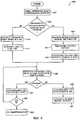
Фиг.3 иллюстрирует процесс 300, выполняемый удаленным устройством для установки протокольных параметров, которые это удаленное устройство использует для связи с центральным устройством. Процесс 300 начинается на шаге 301 с того, что удаленное устройство принимает сигналы от центрального устройства. Эти сигналы сохраняются в буфере на шаге 302. Буфер может быть регистром в процессоре или буфером в интерфейсе, таким как буфер 215, показанный на фиг.2. На шаге 303 удаленное устройство определяет скорость передачи в бодах из сигналов, сохраненных в буфере. После того, как скорость передачи в бодах определена, удаленное устройство определяет протокол и кадровую синхронизацию, с которыми эти сигналы посылаются на шаге 304. Затем удаленное устройство на шаге 305 устанавливает связь с использованием протокольных параметров, которые это удаленное устройство определило из сигналов в буфере, и процесс 300 заканчивается.FIG. 3 illustrates a
Фиг.4 иллюстрирует процесс 400, который является примерным воплощением процесса по выполнению шагов в процессе 300, показанном на фиг.3. Процесс 400 начинается на шаге 401 приемом отсчетов в буфер на максимальной скорости. На шаге 402 удаленное устройство определяет, произошел ли переход заранее заданного уровня между двумя битами после определенного числа отсчетов.FIG. 4 illustrates a
К примеру, начальный бит является известным битом, который отмечает начало кадра данных в любом кадре или протоколе. Если переход уровня между двумя сигналами принимается в определенном числе отсчетов, удаленное устройство на шаге 410 определяет, что скорость передачи в бодах равна n или максимальной скорости передачи в бодах, а n, деленное на 4(n/4), есть минимальная скорость передачи в бодах. Это потому, что скорость в бодах n гарантирует, что переход уровня между двумя битами не может существовать, если скорость в бодах меньше или равна n/8. Поэтому максимальная скорость в бодах устанавливается на n, а минимальная скорость в бодах устанавливается на n/4.For example, the start bit is a known bit that marks the beginning of a data frame in any frame or protocol. If the level transition between the two signals is received in a certain number of samples, the remote device determines in
Если переход уровня между двумя битами не обнаруживается в заранее заданном числе отсчетов на шаге 402, удаленное устройство определяет, что скорость в бодах равна n/8 или меньше. Для того, чтобы принимать нужные сигналы, частоты дискретизации сигналов регулируются на шаге 421. Это изменяет информации о сигналах, хранящихся в буфере. Затем на шаге 422 максимальная скорость в бодах устанавливается на n/8, а минимальная устанавливается на минимальную скорость в бодах, поддерживаемую удаленным устройством.If the level transition between the two bits is not detected in a predetermined number of samples in
После шага 411 или шага 422, которые устанавливают максимальную и минимальную.скорости в бодах, выполняется подпрограмма определения точных протокольных параметров. Эта подпрограмма начинается на шаге 430, на котором выполняется сопоставление шаблонов для максимальной скорости в бодах. В соответствии с данным изобретением шаблон представляет собой сохраненный или генерированный файл, включающий в себя ожидаемые переходы для конкретных отсчетов. Если ожидаемый переход в шаблоне совпадает с переходами в файле, шаблон считается совпадающим.After
Пример сопоставления шаблонов, выполняемый на шаге 430, иллюстрируется в процессе 500 на фиг.5. Если шаблон для протокола на текущей скорости в бодах совпадает с сигналами в буфере, скорость в бодах для удаленного устройства устанавливается равной максимальной скорости в бодах на шаге 440, а протокол и кадровая синхронизация устанавливаются соответствующими протоколу совпадающего шаблона на шаге 441, и процесс 400 заканчивается. Если протокол и скорость передачи в бодах не определяются на шаге 430, максимальная скорость в бодах устанавливается равной текущему максимуму, поделенному на два (Мах/2) на шаге 431.An example pattern matching performed at
На шаге 432 удаленное устройство определяет, меньше ли максимальная скорость передачи в бодах, чем минимальная скорость передачи в бодах. Если максимальная скорость в бодах меньше минимальной скорости в бодах, то удаленное устройство на шаге 432 индицирует, что протокольные параметры не поддерживаются удаленным устройством, и процесс 400 заканчивается. В противном случае шаги 430-432 повторяются с использованием новой максимальной скорости в бодах.In
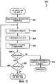
Фиг.5 иллюстрирует процесс 500, который является примерным процессом сопоставления шаблонов, выполняемым на шаге 430 процесса 400. Процесс 500 начинается на шаге 501 с того, что удаленное устройство загружает шаблоны для поддерживаемых протоколов на текущей максимальной скорости передачи в бодах. В это время шаблоны могут либо генерироваться, либо извлекаться из памяти. На шаге 502 считывается шаблон для текущей максимальной скорости в бодах. На шаге 503 считываются сигналы, сохраненные в буфере. Эти сигналы, считанные из буфера, сравниваются на шаге 504 со считанным шаблоном. На шаге 505 определяется, совпадает ли комбинация сигналов, считанных из буфера, с шаблоном ожидаемых сигналов. Следует отметить, что шаблон совпадает лишь с определенными сигналами в каждом кадре и не совпадает со всеми точками. Это имеет место потому, что кадр содержит биты данных, которые не могут совпадать надежно. Вместо этого пытаются установить совпадение шаблона с известными битами, такими как начальный и конечный биты.5 illustrates a
Если сигналы не совпадают с шаблоном на шаге 505, удаленное устройство на шаге 507 определяет, есть ли еще другие шаблоны, подлежащие сравнению. Если имеются еще шаблоны для сравнения, процесс 500 повторяется от шага 502. Если шаблонов больше нет, процесс 500 заканчивается. Если сигналы не совпадают с шаблоном на шаге 505, удаленное устройство устанавливает скорость передачи в бодах на текущую максимальную скорость в бодах, а в качестве протокола - протокол шаблона, сравниваемого на шаге 506. Процесс 500 затем заканчивается.If the signals do not match the pattern in
Один вид устройств, имеющий электронные компоненты, которые могут использовать установку скорости в бодах и протокола, есть кориолисов расходомер. Фиг.6 показывает примерный кориолисов расходомер 5, содержащий узел 10 кориолисова расходомера и измерительную электронную часть 20. Измерительная электронная часть 20 соединяется с узлом 10 расходомера по тракту 600, чтобы обеспечить по тракту 26 информацию о плотности, скорости массопереноса, скорости объемного переноса и обобщенного массопереноса. Описывается конструкция кориолисова расходомера, хотя для специалистов очевидно, что настоящее изобретение может использоваться с любым устройством, имеющим вибрирующий трубопровод для измерения свойств вещества, протекающего через этот трубопровод. Вторым примером такого устройства является измеритель плотности с вибрирующим трубопроводом, который не имеет дополнительной измерительной возможности, предоставляемой кориолисовым массовым расходомером.One type of device that has electronic components that can use the baud rate setting and protocol is a Coriolis flowmeter. 6 shows an
Измерительный узел 10 включает в себя пару фланцев 601 и 601’, ответвитель 602 и трубопроводы 603А и 603В. К трубопроводам 603А и 603В присоединяются возбудитель 604, тензометрические датчики 605 и 605’ и температурный датчик 607. Крепежные планки 606 и 606’ служат для определения осей W и W’, вокруг которых колеблется каждый трубопровод.The measuring
Когда кориолисов расходомер 5 вводится в магистральную систему (не показана), которая переносит измеряемое технологическое вещество, это вещество входит в измерительный узел 10 через фланец 601, проходит через ответвитель 602, где это вещество направляется для введения в трубопроводы 603А и 603В, протекает через трубопроводы 603А и 603В и обратно в ответвитель 602, из которого оно покидает измерительный узел 10 через фланец 601’.When a
Трубопроводы 603А и 603В выбираются и соответственно устанавливаются на ответвителе 602 так, чтобы иметь практически одни и те же распределение масс, моменты инерции и модули упругости относительно изгибных осей W-W и W’-W’ соответственно. Эти трубопроводы проходят снаружи от ответвителя практически параллельно.
Трубопроводы 603А-603В возбуждаются возбудителем 604 в противоположных направлениях относительно своих изгибных осей W-W и W’-W’ и, как отмечено, в первом несинфазном изгибном режиме расходомера. Возбудитель 604 может содержать любую из множества общеизвестных конструкций, таких как магнит, установленный на трубопроводе 603А, и противоположную ему катушку, установленную на трубопроводе 603В, через которую пропускается переменный ток для возбуждения вибрации в обоих трубопроводах. Подходящий сигнал возбуждения прикладывается измерительной электронной частью 20 через тракт 610 к возбудителю 604.
Тензометрические датчики 605 и 605’ прикреплены по меньшей мере к одному из трубопроводов 603А и 603В на противоположных концах этого трубопровода для измерения колебания трубопроводов. Когда трубопровод 603А-603В вибрирует, тензометрические датчики 605-605’ генерируют первый тензометрический сигнал и второй тензометрический сигнал. Эти первый и второй тензометрические сигналы прикладываются к трактам 611 и 611’. Сигнал скорости возбудителя прикладывается к тракту 610.Strain gauges 605 and 605 ’are attached to at least one of the
Температурный датчик 607 прикреплен по меньшей мере к одному трубопроводу 603А и/или 603В. Температурный датчик 607 измеряет температуру трубопровода для того, чтобы модифицировать уравнения для температуры системы. Тракт 612 переносит температурные сигналы от температурного датчика 607 к измерительной электронной части 20.
Измерительная электронная часть 20 принимает первый и второй тензометрические сигналы, появляющиеся на трактах 611 и 611’ соответственно. Измерительная электронная часть 20 обрабатывает первый и второй сигналы скорости для вычисления скорости массопереноса, плотности или иного свойства вещества, проходящего через узел 10 расходомера. Эта вычисленная информация подается в измерительную электронную часть 20 по тракту 26 в использующее средство (не показано).The measuring
Специалистам известно, что кориолисов расходомер 5 совершенно подобен по конструкции измерителю плотности с вибрирующим трубопроводом. Измерители плотности с вибрирующим трубопроводом тоже используют вибрирующую трубу, через которую течет поток, или для случая измерителя плотности отсчетного типа, в котором удерживается текучее вещество. Измерители плотности с вибрирующим трубопроводом тоже применяют возбуждающую систему для того, чтобы заставить трубопровод вибрировать. Измерители плотности с вибрирующим трубопроводом, как правило, используют только единственный сигнал обратной связи, поскольку измерение плотности требует только измерения частоты, а фазовое измерение не нужно. Данное описание настоящего изобретения равным образом применимо к измерителям плотности с вибрирующим трубопроводом.Specialists know that the
В данном изобретении измерительная электронная часть 20 физически разделена на два компонента: центральная система 700 и блок 701 формирования сигналов, который удален от центральной системы 700. В общепринятых схемах измерительной электронной части эти компоненты помещены в один блок.In the present invention, the measuring
Блок 701 формирования сигналов включает в себя схему 710 возбуждения и схему 720 формирования тензометрических сигналов. Специалист поймет, что в действительности схема 710 возбуждения и схема 720 формирования тензометрических сигналов могут быть отдельными аналоговыми схемами или могут быть отдельными функциональными блоками, обеспечиваемыми цифровым сигнальным процессором или иными цифровыми компонентами. Схема 710 возбуждения генерирует возбуждающий сигнал и подает этот возбуждающий сигнал на возбудитель 604 по тракту 610 тракта 600. В действительности тракт 610 является первым и вторым выводом. Схема 710 возбуждения связывается со схемой 720 формирования тензометрических сигналов по тракту 713. Тракт 713 позволяет схеме возбуждения отслеживать поступающие тензометрические сигналы для регулировки сигнала возбуждения. Питание для работы схемы 710 возбуждения и схемы 720 формирования тензометрических сигналов подается от центральной системы 700 по первому проводу 711 и второму проводу 712. Первый провод 711 и второй провод 712 могут быть частью обычного двухпроводного, четырехпроводного кабеля или частью кабеля с множеством пар.The
Схема 720 формирования тензометрических сигналов принимает входные сигналы от первого тензометрического датчика 605, второго тензометрического датчика 605’ и температурного датчика 607 по трактам 611, 611’ и 612. Тензометрическая схема 720 определяет частоту тензометрических сигналов и может также определять свойства вещества, протекающего через трубопроводы 603А-603В. После того, как определены частота входных сигналов от тензометрических датчиков 605-605’ и свойства вещества, сигналы параметров, несущие эту информацию, генерируются и передаются по тракту 721 в блок 750 вторичной обработки в центральной системе 700. В предпочтительном варианте выполнения тракт 721 включает в себя 2 вывода. Однако специалист поймет, что тракт 721 может проходить по первому проводу 711 и второму проводу 712 или по любому другому числу проводов.The strain gauge
Центральная система 700 содержит источник 730 питания и систему 750 обработки. Источник 730 питания принимает электроэнергию от сети и преобразует принятую электроэнергию в требуемое питание, необходимое для системы. Система 750 обработки принимает сигналы параметров от схемы 720 формирования тензометрических сигналов, а затем может выполнять обработку, необходимую для получения свойств вещества, протекающего через трубопроводы 603А-603В, необходимых пользователю. Такие свойства могут включать в себя - но не ограничиваться ими - плотность, скорость массопереноса и скорость объемного переноса.The
В этой конфигурации блок 701 формирования сигналов представляет собой удаленное устройство, осуществляющее связь с центральной системой 700, которая является центральным устройством. Блок 701 формирования сигналов определяет протокольные параметры, которые используются центральной системой 700 для связи. Затем блок 701 формирования сигналов устанавливается для осуществления связи с определенными протокольными параметрами.In this configuration, the
Фиг.7 иллюстрирует предпочтительный примерный процесс, выполняемый блоком 701 формирования сигналов для выявления скорости передачи в бодах, определения используемых протокола и кадровой синхронизации и установки протокольных параметров для осуществления связи в соответствии с настоящим изобретением. Процесс 1700 начинается на шаге 1701 установкой частоты дискретизации для приема сигналов в буфер в три раза выше максимальной поддерживаемой скорости передачи в бодах (3n). На шаге 1702 n сигналов принимаются в буфер.7 illustrates a preferred exemplary process performed by a
На шаге 1703 шаблоны для поддерживаемых протоколов для максимальной скорости передачи в бодах сравниваются с сигналами, хранящимися в буфере. Блок 701 формирования сигналов на шаге 1703 определяет, совпадает ли один из шаблонов с сигналами в буфере. Если эти сигналы совпадают с шаблоном, блок формирования сигналов на шаге 1720 устанавливает в качестве протокола протокол этого совпадающего шаблона и устанавливает скорость передачи в бодах равной максимальной скорости передачи в бодах.In
Если сигналы не совпадают ни с одним из шаблонов для максимальной скорости передачи в бодах, на шаге 1710 максимальная скорость передачи в бодах устанавливается равной максимальной скорости передачи в бодах, поделенной на два (n/2). На шаге 1711 блок 701 формирования сигналов определяет, меньше ли максимальная скорость передачи в бодах, чем три минимальных скорости передачи в бодах (3 min). Если максимальная скорость передачи в бодах меньше, чем утроенная минимальная скорость передачи в бодах, процесс 1700 индицирует на шаге 1714, что этот протокол не поддерживается блоком 701 формирования сигналов.If the signals do not match any of the patterns for the maximum baud rate, in
Если же максимальная скорость передачи в бодах не меньше, чем утроенная минимальная скорость передачи в бодах, блок формирования сигналов на шаге 1730 настраивает буфер для совпадения с новой максимальной скоростью передачи в бодах. Затем на шаге 1731 дополнительные n, деленное на два отсчетов, поступают в буфер, и процесс 1700 повторяется с шага 1703.If the maximum baud rate is not less than the tripled minimum baud rate, the signal generation unit in
Выше приведено описание системы для установки протокольных параметров для осуществления связи в устройстве в соответствии с настоящим изобретением. Очевидно, что специалисты сконструируют альтернативные системы для установки "протокольных/УАПП параметров" для осуществления связи в соответствии с настоящим изобретением, которые будут нарушать данное изобретение, как оно изложено в нижеследующей формуле изобретения, либо буквально, либо через доктрину эквивалентов.The above is a description of a system for setting protocol parameters for communicating in a device in accordance with the present invention. It will be appreciated that those skilled in the art will design alternative systems for setting “protocol / UAPT parameters” for communicating in accordance with the present invention, which would violate this invention as set forth in the following claims, either literally or through the doctrine of equivalents.
Claims (18)
Translated fromRussianApplications Claiming Priority (4)
| Application Number | Priority Date | Filing Date | Title |
|---|---|---|---|
| US15972599P | 1999-10-15 | 1999-10-15 | |
| US60/159,725 | 1999-10-15 | ||
| US09/569,657US6678751B1 (en) | 1999-10-15 | 2000-05-12 | System for setting frame and protocol for transmission in a UART device |
| US09/569,657 | 2000-05-12 |
Publications (2)
| Publication Number | Publication Date |
|---|---|
| RU2002112987A RU2002112987A (en) | 2004-02-10 |
| RU2235439C2true RU2235439C2 (en) | 2004-08-27 |
Family
ID=26856216
Family Applications (1)
| Application Number | Title | Priority Date | Filing Date |
|---|---|---|---|
| RU2002112987/09ARU2235439C2 (en) | 1999-10-15 | 2000-10-10 | System for determining transmission protocol basing on detected transmission speed in bauds |
Country Status (16)
| Country | Link |
|---|---|
| US (1) | US6678751B1 (en) |
| EP (1) | EP1222783B1 (en) |
| JP (1) | JP2003512772A (en) |
| KR (1) | KR100557709B1 (en) |
| CN (1) | CN1211985C (en) |
| AR (1) | AR025974A1 (en) |
| AT (1) | ATE320131T1 (en) |
| AU (1) | AU770583B2 (en) |
| BR (1) | BRPI0014688B1 (en) |
| CA (1) | CA2386319C (en) |
| DE (1) | DE60026572T2 (en) |
| DK (1) | DK1222783T3 (en) |
| MX (1) | MXPA02003633A (en) |
| MY (1) | MY124204A (en) |
| RU (1) | RU2235439C2 (en) |
| WO (1) | WO2001030038A1 (en) |
Cited By (2)
| Publication number | Priority date | Publication date | Assignee | Title |
|---|---|---|---|---|
| RU2437223C2 (en)* | 2007-06-12 | 2011-12-20 | Квэлкомм Инкорпорейтед | Matching of transfer speed at multiple sizes of code units |
| US9686044B2 (en) | 2007-03-27 | 2017-06-20 | Qualcomm Incorporated | Rate matching with multiple code block sizes |
Families Citing this family (37)
| Publication number | Priority date | Publication date | Assignee | Title |
|---|---|---|---|---|
| US6880015B1 (en)* | 2000-02-25 | 2005-04-12 | Square D Company | Agile mode for Modbus network protocol |
| US11467856B2 (en) | 2002-12-12 | 2022-10-11 | Flexiworld Technologies, Inc. | Portable USB device for internet access service |
| US10860290B2 (en) | 2000-11-01 | 2020-12-08 | Flexiworld Technologies, Inc. | Mobile information apparatuses that include a digital camera, a touch sensitive screen interface, support for voice activated commands, and a wireless communication chip or chipset supporting IEEE 802.11 |
| AU2002243279A1 (en) | 2000-11-01 | 2002-06-18 | Flexiworld Technologies, Inc. | Controller and manager for device-to-device pervasive digital output |
| US11204729B2 (en) | 2000-11-01 | 2021-12-21 | Flexiworld Technologies, Inc. | Internet based digital content services for pervasively providing protected digital content to smart devices based on having subscribed to the digital content service |
| US10915296B2 (en) | 2000-11-01 | 2021-02-09 | Flexiworld Technologies, Inc. | Information apparatus that includes a touch sensitive screen interface for managing or replying to e-mails |
| AU2002239325A1 (en) | 2000-11-20 | 2002-05-27 | Flexiworld Technologies, Inc. | Systems and methods for mobile and pervasive output |
| US20020099884A1 (en) | 2001-01-19 | 2002-07-25 | Chang William Ho | Output controller systems and method for universal data output |
| US8812706B1 (en) | 2001-09-06 | 2014-08-19 | Qualcomm Incorporated | Method and apparatus for compensating for mismatched delays in signals of a mobile display interface (MDDI) system |
| US7032045B2 (en)* | 2001-09-18 | 2006-04-18 | Invensys Systems, Inc. | Multi-protocol bus device |
| DE10232988B4 (en)* | 2002-07-19 | 2007-11-22 | Infineon Technologies Ag | Method and device for the clocked output of asynchronously received digital signals |
| WO2004055638A2 (en) | 2002-12-12 | 2004-07-01 | Flexiworld Technologies, Inc. | Wireless communication between computing devices |
| US7076033B2 (en)* | 2003-03-31 | 2006-07-11 | Research In Motion Limited | Bit rate matching system and method |
| CN101208657B (en) | 2003-04-11 | 2017-11-14 | 富意科技 | Portable integrated circuit storage device and operation method thereof |
| WO2004110021A2 (en) | 2003-06-02 | 2004-12-16 | Qualcomm Incorporated | Generating and implementing a signal protocol and interface for higher data rates |
| US7792122B2 (en)* | 2003-07-28 | 2010-09-07 | Nagra Thomson Licensing | Transmission protocol automatic detection method for a portable object such as a chip card or a chip key |
| BRPI0414229A (en) | 2003-09-10 | 2006-10-31 | Qualcomm Inc | high data rate interface |
| AU2004306903C1 (en) | 2003-10-15 | 2009-01-22 | Qualcomm Incorporated | High data rate interface |
| EP2242231A1 (en)* | 2003-11-12 | 2010-10-20 | Qualcomm Incorporated | High data rate interface with improved link control |
| EP1733537A1 (en) | 2004-03-10 | 2006-12-20 | Qualcomm, Incorporated | High data rate interface apparatus and method |
| CN1993948A (en)* | 2004-06-04 | 2007-07-04 | 高通股份有限公司 | High data rate interface apparatus and method |
| US8873584B2 (en) | 2004-11-24 | 2014-10-28 | Qualcomm Incorporated | Digital data interface device |
| US8692838B2 (en) | 2004-11-24 | 2014-04-08 | Qualcomm Incorporated | Methods and systems for updating a buffer |
| US8692839B2 (en) | 2005-11-23 | 2014-04-08 | Qualcomm Incorporated | Methods and systems for updating a buffer |
| US8793390B2 (en)* | 2006-05-23 | 2014-07-29 | Blue Coat Systems, Inc. | Systems and methods for protocol detection in a proxy |
| US8279989B2 (en)* | 2006-08-02 | 2012-10-02 | Entropic Communications, Inc. | Device and process for data rate acquisition |
| US8332499B2 (en)* | 2008-12-04 | 2012-12-11 | Sony Computer Entertainment Inc. | Virtual space management system |
| US20100146409A1 (en)* | 2008-12-04 | 2010-06-10 | Sony Computer Entertainment Inc. | Virtual Space Management System |
| FR2963716A1 (en)* | 2010-08-06 | 2012-02-10 | Sagemcom Energy & Telecom Sas | Data acquiring device i.e. remote information sensor, operation managing method for electric consumption meter, involves adopting operation mode of data acquiring device to specific transmission mode based on determined transmission mode |
| CN103514127A (en)* | 2012-06-15 | 2014-01-15 | 中国航天科工集团第三研究院第八三五八研究所 | Implementation method for achieving self-adaption of baud rate |
| CN102929825B (en)* | 2012-10-15 | 2016-04-13 | 天地融科技股份有限公司 | A kind of method of multiplexing USB interface transmission data and electric signing tools |
| EP2887758A1 (en)* | 2013-12-20 | 2015-06-24 | Nokia Solutions and Networks Oy | Base Station Protocol Determination |
| CN104053174B (en)* | 2014-05-29 | 2018-03-27 | 大唐移动通信设备有限公司 | Based on the adaptive method and device of FPGA Base Band Unit equipment RRU interface protocols |
| KR101632835B1 (en)* | 2015-04-14 | 2016-06-23 | 엘에스산전 주식회사 | Method of auto setting protoco in programmable logic controller system |
| US11206150B2 (en)* | 2018-11-29 | 2021-12-21 | Johnson Controls Tyco IP Holdings LLP | Controller with automatic field bus protocol detection |
| CN110414192B (en)* | 2019-06-14 | 2023-09-26 | 尚承科技股份有限公司 | Control and management system and method applied to safety manufacture |
| CN115529363A (en)* | 2022-09-30 | 2022-12-27 | 三一电动车科技有限公司 | Gateway, communication method, communication system, and operating machine |
Citations (6)
| Publication number | Priority date | Publication date | Assignee | Title |
|---|---|---|---|---|
| US5020132A (en)* | 1987-08-14 | 1991-05-28 | Ericsson Ge Mobile Communications Inc. | Processor-to-processor communications protocol for a public service trunking system |
| US5490209A (en)* | 1994-02-09 | 1996-02-06 | Harris Corporation | Autobaud rate detection mechanism |
| US5684472A (en)* | 1996-05-08 | 1997-11-04 | Motorola, Inc. | Method and apparatus for remotely accessing meter status information in a meter reading system |
| RU2126593C1 (en)* | 1994-10-14 | 1999-02-20 | Интернэшнл Бизнес Машинз Корпорейшн | Controller for communicating with set of protocols by means of directed infrared radiation |
| EP0918421A1 (en)* | 1997-11-13 | 1999-05-26 | Optimay GmbH | Baud rate detection in serial data transmission |
| RU2138122C1 (en)* | 1989-08-14 | 1999-09-20 | ИнтерДигитал Текнолоджи Корпорейшн | Subscriber station in wireless subscriber communication system |
Family Cites Families (7)
| Publication number | Priority date | Publication date | Assignee | Title |
|---|---|---|---|---|
| US3747074A (en)* | 1972-03-17 | 1973-07-17 | Comteu | Method of and apparatus for baud rate detection |
| US5674003A (en)* | 1995-04-28 | 1997-10-07 | Andersen; David B. | Mechanisms for accessing unique features of telephony networks from a protocol-Independent data transport interface |
| US5923705A (en)* | 1996-07-18 | 1999-07-13 | Qualcomm Incorporated | UART based autobauding without data loss |
| JP3156611B2 (en)* | 1996-11-22 | 2001-04-16 | 日本電気株式会社 | Data demultiplexer |
| US5938731A (en)* | 1997-06-23 | 1999-08-17 | International Business Machines Corporation | Exchanging synchronous data link control (SDLC) frames to adjust speed of data transfer between a client and server |
| US6052737A (en)* | 1998-04-15 | 2000-04-18 | International Business Machines Corporation | Computer system, program product and method for dynamically optimizing a communication protocol for supporting more users |
| US6163586A (en)* | 1998-12-01 | 2000-12-19 | Philips Electronics North America Corp. | Autobaud/autoecho method |
- 2000
- 2000-05-12USUS09/569,657patent/US6678751B1/ennot_activeExpired - Lifetime
- 2000-10-06ARARP000105281Apatent/AR025974A1/enactiveIP Right Grant
- 2000-10-10CNCNB008172137Apatent/CN1211985C/ennot_activeExpired - Lifetime
- 2000-10-10AUAU16324/01Apatent/AU770583B2/ennot_activeExpired
- 2000-10-10KRKR1020027004810Apatent/KR100557709B1/ennot_activeExpired - Fee Related
- 2000-10-10CACA002386319Apatent/CA2386319C/ennot_activeExpired - Lifetime
- 2000-10-10DKDK00978916Tpatent/DK1222783T3/enactive
- 2000-10-10JPJP2001531272Apatent/JP2003512772A/enactivePending
- 2000-10-10MXMXPA02003633Apatent/MXPA02003633A/enactiveIP Right Grant
- 2000-10-10EPEP00978916Apatent/EP1222783B1/ennot_activeExpired - Lifetime
- 2000-10-10DEDE60026572Tpatent/DE60026572T2/ennot_activeExpired - Lifetime
- 2000-10-10ATAT00978916Tpatent/ATE320131T1/ennot_activeIP Right Cessation
- 2000-10-10RURU2002112987/09Apatent/RU2235439C2/enactive
- 2000-10-10BRBRPI0014688Apatent/BRPI0014688B1/enactiveIP Right Grant
- 2000-10-10WOPCT/US2000/041103patent/WO2001030038A1/enactiveIP Right Grant
- 2000-10-11MYMYPI20004746Apatent/MY124204A/enunknown
Patent Citations (6)
| Publication number | Priority date | Publication date | Assignee | Title |
|---|---|---|---|---|
| US5020132A (en)* | 1987-08-14 | 1991-05-28 | Ericsson Ge Mobile Communications Inc. | Processor-to-processor communications protocol for a public service trunking system |
| RU2138122C1 (en)* | 1989-08-14 | 1999-09-20 | ИнтерДигитал Текнолоджи Корпорейшн | Subscriber station in wireless subscriber communication system |
| US5490209A (en)* | 1994-02-09 | 1996-02-06 | Harris Corporation | Autobaud rate detection mechanism |
| RU2126593C1 (en)* | 1994-10-14 | 1999-02-20 | Интернэшнл Бизнес Машинз Корпорейшн | Controller for communicating with set of protocols by means of directed infrared radiation |
| US5684472A (en)* | 1996-05-08 | 1997-11-04 | Motorola, Inc. | Method and apparatus for remotely accessing meter status information in a meter reading system |
| EP0918421A1 (en)* | 1997-11-13 | 1999-05-26 | Optimay GmbH | Baud rate detection in serial data transmission |
Cited By (2)
| Publication number | Priority date | Publication date | Assignee | Title |
|---|---|---|---|---|
| US9686044B2 (en) | 2007-03-27 | 2017-06-20 | Qualcomm Incorporated | Rate matching with multiple code block sizes |
| RU2437223C2 (en)* | 2007-06-12 | 2011-12-20 | Квэлкомм Инкорпорейтед | Matching of transfer speed at multiple sizes of code units |
Also Published As
| Publication number | Publication date |
|---|---|
| CN1211985C (en) | 2005-07-20 |
| KR20020060198A (en) | 2002-07-16 |
| MXPA02003633A (en) | 2002-10-23 |
| DE60026572D1 (en) | 2006-05-04 |
| EP1222783A1 (en) | 2002-07-17 |
| CA2386319A1 (en) | 2001-04-26 |
| CN1409909A (en) | 2003-04-09 |
| AU1632401A (en) | 2001-04-30 |
| MY124204A (en) | 2006-06-30 |
| DK1222783T3 (en) | 2006-04-10 |
| EP1222783B1 (en) | 2006-03-08 |
| ATE320131T1 (en) | 2006-03-15 |
| KR100557709B1 (en) | 2006-03-07 |
| BRPI0014688B1 (en) | 2017-03-14 |
| WO2001030038A1 (en) | 2001-04-26 |
| AU770583B2 (en) | 2004-02-26 |
| DE60026572T2 (en) | 2006-08-10 |
| US6678751B1 (en) | 2004-01-13 |
| RU2002112987A (en) | 2004-02-10 |
| AR025974A1 (en) | 2002-12-26 |
| HK1053397A1 (en) | 2003-10-17 |
| JP2003512772A (en) | 2003-04-02 |
| CA2386319C (en) | 2006-10-03 |
| BR0014688A (en) | 2002-06-11 |
Similar Documents
| Publication | Publication Date | Title |
|---|---|---|
| RU2235439C2 (en) | System for determining transmission protocol basing on detected transmission speed in bauds | |
| JP3679752B2 (en) | Shape identification for Coriolis flow meter drive control | |
| RU2387954C2 (en) | Programmed electronic facilities of coriolis flowmetre, method of electronic facilities operation and processor-readable media of program product | |
| JP4850957B2 (en) | System for preventing unauthorized operation of signal conditioning device located remotely from host system | |
| WO2001092832A2 (en) | Method and apparatus to control power drawn by a measurement device | |
| JP2002527838A (en) | Multi-mode I/O signal transmission circuit | |
| PL199112B1 (en) | System for setting transmission protocol based on detected baud rate | |
| HK1053397B (en) | System for setting transmission protocol based on detected baud rate |