RU2226405C2 - Container manufactured from liquid crystal polymer for sterilizing instruments - Google Patents
Container manufactured from liquid crystal polymer for sterilizing instrumentsInfo
- Publication number
- RU2226405C2 RU2226405C2RU97111184/14ARU97111184ARU2226405C2RU 2226405 C2RU2226405 C2RU 2226405C2RU 97111184/14 ARU97111184/14 ARU 97111184/14ARU 97111184 ARU97111184 ARU 97111184ARU 2226405 C2RU2226405 C2RU 2226405C2
- Authority
- RU
- Russia
- Prior art keywords
- sterilization
- container
- tray
- liquid crystal
- chemical
- Prior art date
Links
Images


Classifications
- A—HUMAN NECESSITIES
- A61—MEDICAL OR VETERINARY SCIENCE; HYGIENE
- A61L—METHODS OR APPARATUS FOR STERILISING MATERIALS OR OBJECTS IN GENERAL; DISINFECTION, STERILISATION OR DEODORISATION OF AIR; CHEMICAL ASPECTS OF BANDAGES, DRESSINGS, ABSORBENT PADS OR SURGICAL ARTICLES; MATERIALS FOR BANDAGES, DRESSINGS, ABSORBENT PADS OR SURGICAL ARTICLES
- A61L2/00—Methods or apparatus for disinfecting or sterilising materials or objects other than foodstuffs or contact lenses; Accessories therefor
- A61L2/26—Accessories or devices or components used for biocidal treatment
- B—PERFORMING OPERATIONS; TRANSPORTING
- B65—CONVEYING; PACKING; STORING; HANDLING THIN OR FILAMENTARY MATERIAL
- B65D—CONTAINERS FOR STORAGE OR TRANSPORT OF ARTICLES OR MATERIALS, e.g. BAGS, BARRELS, BOTTLES, BOXES, CANS, CARTONS, CRATES, DRUMS, JARS, TANKS, HOPPERS, FORWARDING CONTAINERS; ACCESSORIES, CLOSURES, OR FITTINGS THEREFOR; PACKAGING ELEMENTS; PACKAGES
- B65D1/00—Rigid or semi-rigid containers having bodies formed in one piece, e.g. by casting metallic material, by moulding plastics, by blowing vitreous material, by throwing ceramic material, by moulding pulped fibrous material or by deep-drawing operations performed on sheet material
- B65D1/02—Bottles or similar containers with necks or like restricted apertures, designed for pouring contents
- B65D1/0207—Bottles or similar containers with necks or like restricted apertures, designed for pouring contents characterised by material, e.g. composition, physical features
- C—CHEMISTRY; METALLURGY
- C08—ORGANIC MACROMOLECULAR COMPOUNDS; THEIR PREPARATION OR CHEMICAL WORKING-UP; COMPOSITIONS BASED THEREON
- C08K—Use of inorganic or non-macromolecular organic substances as compounding ingredients
- C08K3/00—Use of inorganic substances as compounding ingredients
- C08K3/40—Glass
- C—CHEMISTRY; METALLURGY
- C08—ORGANIC MACROMOLECULAR COMPOUNDS; THEIR PREPARATION OR CHEMICAL WORKING-UP; COMPOSITIONS BASED THEREON
- C08L—COMPOSITIONS OF MACROMOLECULAR COMPOUNDS
- C08L31/00—Compositions of homopolymers or copolymers of compounds having one or more unsaturated aliphatic radicals, each having only one carbon-to-carbon double bond, and at least one being terminated by an acyloxy radical of a saturated carboxylic acid, of carbonic acid or of a haloformic acid; Compositions of derivatives of such polymers
- C08L31/06—Homopolymers or copolymers of esters of polycarboxylic acids
- C08L31/08—Homopolymers or copolymers of esters of polycarboxylic acids of phthalic acid
- A—HUMAN NECESSITIES
- A61—MEDICAL OR VETERINARY SCIENCE; HYGIENE
- A61L—METHODS OR APPARATUS FOR STERILISING MATERIALS OR OBJECTS IN GENERAL; DISINFECTION, STERILISATION OR DEODORISATION OF AIR; CHEMICAL ASPECTS OF BANDAGES, DRESSINGS, ABSORBENT PADS OR SURGICAL ARTICLES; MATERIALS FOR BANDAGES, DRESSINGS, ABSORBENT PADS OR SURGICAL ARTICLES
- A61L2/00—Methods or apparatus for disinfecting or sterilising materials or objects other than foodstuffs or contact lenses; Accessories therefor
- A61L2/02—Methods or apparatus for disinfecting or sterilising materials or objects other than foodstuffs or contact lenses; Accessories therefor using physical phenomena
- A61L2/04—Heat
- A61L2/06—Hot gas
- A61L2/07—Steam
- A—HUMAN NECESSITIES
- A61—MEDICAL OR VETERINARY SCIENCE; HYGIENE
- A61L—METHODS OR APPARATUS FOR STERILISING MATERIALS OR OBJECTS IN GENERAL; DISINFECTION, STERILISATION OR DEODORISATION OF AIR; CHEMICAL ASPECTS OF BANDAGES, DRESSINGS, ABSORBENT PADS OR SURGICAL ARTICLES; MATERIALS FOR BANDAGES, DRESSINGS, ABSORBENT PADS OR SURGICAL ARTICLES
- A61L2/00—Methods or apparatus for disinfecting or sterilising materials or objects other than foodstuffs or contact lenses; Accessories therefor
- A61L2/02—Methods or apparatus for disinfecting or sterilising materials or objects other than foodstuffs or contact lenses; Accessories therefor using physical phenomena
- A61L2/14—Plasma, i.e. ionised gases
- A—HUMAN NECESSITIES
- A61—MEDICAL OR VETERINARY SCIENCE; HYGIENE
- A61L—METHODS OR APPARATUS FOR STERILISING MATERIALS OR OBJECTS IN GENERAL; DISINFECTION, STERILISATION OR DEODORISATION OF AIR; CHEMICAL ASPECTS OF BANDAGES, DRESSINGS, ABSORBENT PADS OR SURGICAL ARTICLES; MATERIALS FOR BANDAGES, DRESSINGS, ABSORBENT PADS OR SURGICAL ARTICLES
- A61L2/00—Methods or apparatus for disinfecting or sterilising materials or objects other than foodstuffs or contact lenses; Accessories therefor
- A61L2/16—Methods or apparatus for disinfecting or sterilising materials or objects other than foodstuffs or contact lenses; Accessories therefor using chemical substances
- A61L2/20—Gaseous substances, e.g. vapours
- A61L2/206—Ethylene oxide
- A—HUMAN NECESSITIES
- A61—MEDICAL OR VETERINARY SCIENCE; HYGIENE
- A61L—METHODS OR APPARATUS FOR STERILISING MATERIALS OR OBJECTS IN GENERAL; DISINFECTION, STERILISATION OR DEODORISATION OF AIR; CHEMICAL ASPECTS OF BANDAGES, DRESSINGS, ABSORBENT PADS OR SURGICAL ARTICLES; MATERIALS FOR BANDAGES, DRESSINGS, ABSORBENT PADS OR SURGICAL ARTICLES
- A61L2/00—Methods or apparatus for disinfecting or sterilising materials or objects other than foodstuffs or contact lenses; Accessories therefor
- A61L2/16—Methods or apparatus for disinfecting or sterilising materials or objects other than foodstuffs or contact lenses; Accessories therefor using chemical substances
- A61L2/20—Gaseous substances, e.g. vapours
- A61L2/208—Hydrogen peroxide
- A—HUMAN NECESSITIES
- A61—MEDICAL OR VETERINARY SCIENCE; HYGIENE
- A61L—METHODS OR APPARATUS FOR STERILISING MATERIALS OR OBJECTS IN GENERAL; DISINFECTION, STERILISATION OR DEODORISATION OF AIR; CHEMICAL ASPECTS OF BANDAGES, DRESSINGS, ABSORBENT PADS OR SURGICAL ARTICLES; MATERIALS FOR BANDAGES, DRESSINGS, ABSORBENT PADS OR SURGICAL ARTICLES
- A61L2202/00—Aspects relating to methods or apparatus for disinfecting or sterilising materials or objects
- A61L2202/10—Apparatus features
- A61L2202/12—Apparatus for isolating biocidal substances from the environment
- A61L2202/122—Chambers for sterilisation
- A—HUMAN NECESSITIES
- A61—MEDICAL OR VETERINARY SCIENCE; HYGIENE
- A61L—METHODS OR APPARATUS FOR STERILISING MATERIALS OR OBJECTS IN GENERAL; DISINFECTION, STERILISATION OR DEODORISATION OF AIR; CHEMICAL ASPECTS OF BANDAGES, DRESSINGS, ABSORBENT PADS OR SURGICAL ARTICLES; MATERIALS FOR BANDAGES, DRESSINGS, ABSORBENT PADS OR SURGICAL ARTICLES
- A61L2202/00—Aspects relating to methods or apparatus for disinfecting or sterilising materials or objects
- A61L2202/10—Apparatus features
- A61L2202/18—Aseptic storing means
- A61L2202/182—Rigid packaging means
- A—HUMAN NECESSITIES
- A61—MEDICAL OR VETERINARY SCIENCE; HYGIENE
- A61L—METHODS OR APPARATUS FOR STERILISING MATERIALS OR OBJECTS IN GENERAL; DISINFECTION, STERILISATION OR DEODORISATION OF AIR; CHEMICAL ASPECTS OF BANDAGES, DRESSINGS, ABSORBENT PADS OR SURGICAL ARTICLES; MATERIALS FOR BANDAGES, DRESSINGS, ABSORBENT PADS OR SURGICAL ARTICLES
- A61L2202/00—Aspects relating to methods or apparatus for disinfecting or sterilising materials or objects
- A61L2202/20—Targets to be treated
- A61L2202/24—Medical instruments, e.g. endoscopes, catheters, sharps
Landscapes
- Health & Medical Sciences (AREA)
- Chemical & Material Sciences (AREA)
- Epidemiology (AREA)
- Life Sciences & Earth Sciences (AREA)
- Animal Behavior & Ethology (AREA)
- General Health & Medical Sciences (AREA)
- Public Health (AREA)
- Veterinary Medicine (AREA)
- Polymers & Plastics (AREA)
- Chemical Kinetics & Catalysis (AREA)
- Organic Chemistry (AREA)
- Engineering & Computer Science (AREA)
- Medicinal Chemistry (AREA)
- Ceramic Engineering (AREA)
- Mechanical Engineering (AREA)
- Apparatus For Disinfection Or Sterilisation (AREA)
- Containers Having Bodies Formed In One Piece (AREA)
- Packging For Living Organisms, Food Or Medicinal Products That Are Sensitive To Environmental Conditiond (AREA)
- Polyesters Or Polycarbonates (AREA)
- Packages (AREA)
- Liquid Crystal Substances (AREA)
- Medical Preparation Storing Or Oral Administration Devices (AREA)
Abstract
Description
Translated fromRussianОбласть техники, к которой относится изобретениеFIELD OF THE INVENTION
Изобретение относится к стерилизационному контейнеру, предназначенному для использования при стерилизации, хранении, переноске и подаче инструментов, в особенности медицинских инструментов.The invention relates to a sterilization container for use in sterilization, storage, carrying and feeding of instruments, in particular medical instruments.
Предпосылки создания изобретенияBACKGROUND OF THE INVENTION
Большая часть допускающих повторное применение медицинских инструментов нуждается в стерилизации перед каждым использованием. Много способов используют для стерилизации, но большая часть широко распространенных способов охватывает стерилизацию паром, химическую стерилизацию в паровой фазе и химическую стерилизацию в паровой фазе в сочетании с полем плазмы. Химические стерилизаторы включают пероксид водорода и этиленоксид. В одном из наиболее усовершенствованных, быстрых и наиболее эффективных способов предусматривается начальная стадия достижения паровой фазы пероксида водорода с последующим приложением электромагнитного поля, которое возбуждает пары пероксида водорода и создает плазменное состояние вещества. Плазменная фаза усиливает стерилизацию, а когда электромагнитное поле отключают, свободные радикалы плазмы рекомбинируют с образованием воды и кислорода.Most reusable medical instruments need sterilization before each use. Many methods are used for sterilization, but most of the widely used methods include steam sterilization, chemical vapor sterilization and chemical vapor sterilization combined with a plasma field. Chemical sterilizers include hydrogen peroxide and ethylene oxide. In one of the most advanced, fastest and most effective methods, an initial stage is provided for reaching the vapor phase of hydrogen peroxide, followed by the application of an electromagnetic field that excites hydrogen peroxide vapor and creates a plasma state of the substance. The plasma phase enhances sterilization, and when the electromagnetic field is turned off, the free radicals of the plasma recombine to form water and oxygen.
В типичном случае инструменты помещают в контейнер, а затем контейнер устанавливают в стерилизационное устройство. Необходимо предусматривать каналы для прохождения стерилизующей среды. Кроме того, обычно контейнер снабжают фильтровальным материалом, который позволяет стерилизующей среде проходить через каналы, а контейнер при этом предохраняется от проникновения микроорганизмов. Канал и фильтровальный материал могут составлять одно целое, как в патенте США №4704254, опубликованном 3 ноября 1987 г. (автор: Nichols), который включен в описание настоящего изобретения для ссылки, или в контейнере можно предусмотреть множество отверстий, а затем перед каждой стерилизацией заворачивать контейнер в фильтровальный оберточный материал, такой как SPUNGUARD, торговое название CSR, поставляемый корпорацией Kimberly Clark Corporation, который представляет собой клеевой/расплавленный пористый/клеевой материал, состоящий из нетканых внешних слоев полиолефинов и внутреннего барьерного слоя из расплавленных пористых полиолефинов.Typically, the instruments are placed in a container, and then the container is installed in a sterilization device. It is necessary to provide channels for the passage of the sterilizing medium. In addition, usually the container is equipped with filter material that allows the sterilizing medium to pass through the channels, and the container is thus protected from the penetration of microorganisms. The channel and filter material may be integral, as in US Pat. No. 4,704,254, published November 3, 1987 (author: Nichols), which is incorporated herein by reference, or a plurality of holes may be provided in a container, and then before each sterilization wrap the container in a filter wrapper such as SPUNGUARD, CSR trademark supplied by Kimberly Clark Corporation, which is an adhesive / molten porous / adhesive material consisting of nonwoven outer layers of poly lefins and the inner barrier layer of molten porous polyolefins.
Обычно удерживающие устройства того или иного вида фиксируют один или несколько инструментов внутри контейнера. Удерживающее устройство может содержать зажимы или другие аналогичные приспособления, которые могут быть, а могут и не быть, специально рассчитаны для фиксации отдельного инструмента. Одно широко известное удерживающее устройство просто содержит множество вытянутых кверху, гибких шипов, иногда называемых пальцами, которые предотвращают перемещение инструментов внутри контейнера и находятся в минимальном соприкосновении с инструментами. В типичном случае они предусмотрены на подставке, лежащей на дне контейнера.Usually holding devices of one kind or another fix one or more instruments inside the container. The holding device may comprise clamps or other similar devices, which may or may not be specially designed to hold a single tool. One well-known holding device simply contains a plurality of upwardly extending, flexible spikes, sometimes called fingers, which prevent tools from moving inside the container and are in minimal contact with the tools. Typically, they are provided on a stand lying at the bottom of the container.
Идеальный стерилизационный лоток или контейнер совместим со всеми основными способами стерилизации; в нем предельно снижен сбор конденсата через тонкие, но все же прочные стенки; он имеет большой срок службы, удобен в эксплуатации и может быть приобретен по приемлемой цене.The ideal sterilization tray or container is compatible with all major sterilization methods; condensate collection through thin, but still strong walls is extremely reduced in it; It has a long service life, is easy to use and can be purchased at an affordable price.
Контейнеры, известные в настоящее время, имеют недостатки, которые ограничивают их показатели в одной или нескольких из этих областей. Например, многие лотки рассчитаны для паровых стерилизаторов и выполнены из стали, которая в некоторых системах вступает во взаимодействие с образованием плазмы. Другие лотки, выполненные из полимеров, не имеют достаточной термостойкости, чтобы противостоять повторяющимся циклам паровой стерилизации. Некоторые материалы лотков взаимодействуют с химическими стерилизаторами и могут даже разлагать стерилизатор. Другие материалы могут поглощать избыточные количества химических стерилизаторов, в связи с чем снижается эффективность стерилизации за счет уменьшения количества стерилизатора, действительно используемого для стерилизации. Currently known containers have drawbacks that limit their performance in one or more of these areas. For example, many trays are designed for steam sterilizers and are made of steel, which in some systems interacts with the formation of plasma. Other trays made of polymers do not have sufficient heat resistance to withstand repeated steam sterilization cycles. Some tray materials interact with chemical sterilizers and may even decompose the sterilizer. Other materials can absorb excess amounts of chemical sterilizers, which reduces the sterilization efficiency by reducing the amount of sterilizer actually used for sterilization.
Сущность изобретенияSUMMARY OF THE INVENTION
В настоящем изобретении устранены эти и другие недостатки известного уровня техники и обеспечена совместимость со способами стерилизации паром пероксида водорода, жидкостью или газовой плазмой, с паровой стерилизацией, стерилизацией этиленоксидом и с другими химическими и термическими способами стерилизации. Оно обладает большим сроком службы, является недорогим в производстве, повышает эффективность дренажа и ограничивает улавливание конденсата.The present invention eliminated these and other drawbacks of the prior art and provides compatibility with methods for steam sterilization of hydrogen peroxide, liquid or gas plasma, with steam sterilization, sterilization with ethylene oxide and other chemical and thermal sterilization methods. It has a long service life, is inexpensive to manufacture, increases drainage efficiency and limits condensate collection.
Стерилизационный контейнер для стерилизации инструментов согласно настоящему изобретению содержит оболочку, ограничивающую контейнер, средство для удержания медицинского инструмента внутри контейнера и одно или большее количество отверстий для впуска стерилизующих газов. Оболочка выполнена из термопластического жидкокристаллического полимера, посредством чего оболочка противостоит химической агрессии пероксида водорода, этиленоксида и других химических стерилизаторов или их исходных веществ, оболочка чрезмерно не взаимодействует ни с какими электромагнитными полями и оболочка противостоит агрессивному воздействию повышенных температур.The sterilizing container for sterilizing instruments according to the present invention comprises a shell defining the container, means for holding the medical instrument inside the container, and one or more sterilizing gas inlets. The shell is made of a thermoplastic liquid crystal polymer, whereby the shell resists the chemical aggression of hydrogen peroxide, ethylene oxide and other chemical sterilizers or their starting materials, the shell does not interact excessively with any electromagnetic fields and the shell resists the aggressive effects of elevated temperatures.
Предпочтительно, термопластический жидкокристаллический полимер включает полностью ароматический полиэфир. Жидкокристаллический полимер, предпочтительно, выбирают из группы, состоящей из полибензоатнафталата, полибензоат-терефталат-бис-фенолизофталата, полибензоат-терефталат-этиленгликоля и полинафталат-аминотерефталата. Жидкокристаллический полимер может быть армирован наполнителем, таким как стеклянные, минеральные волокна или фторполимеры в виде порошка, крошки или волокон.Preferably, the thermoplastic liquid crystal polymer comprises a fully aromatic polyester. The liquid crystal polymer is preferably selected from the group consisting of polybenzoate naphthalate, polybenzoate terephthalate bis phenol isophthalate, polybenzoate terephthalate ethylene glycol and polynaphthalate aminoterephthalate. The liquid crystal polymer may be reinforced with a filler such as glass, mineral fibers or fluoropolymers in the form of powder, chips or fibers.
Краткое описание чертежейBrief Description of the Drawings
Фиг.1 - перспективное изображение стерилизационного контейнера согласно изобретению с пространственным разделением деталей;Figure 1 is a perspective image of a sterilization container according to the invention with a spatial separation of the parts;
фиг.2 - перспективный вид собранного стерилизационного контейнера по фиг.1;figure 2 is a perspective view of the assembled sterilization container of figure 1;
фиг.3 - перспективный вид перевернутой крышки стерилизационного контейнера по фиг.1;figure 3 is a perspective view of the inverted lid of the sterilization container of figure 1;
фиг.4 - поперечное сечение, взятое по линии 4-4 на фиг.2;figure 4 is a cross section taken along the line 4-4 in figure 2;
фиг.5 - перспективное изображение части стерилизационного контейнера в разобранном виде согласно настоящему изобретению, которое иллюстрирует альтернативный запорный механизм по настоящему изобретению;5 is an exploded perspective view of a portion of a sterilization container according to the present invention, which illustrates an alternative closure mechanism of the present invention;
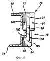
фиг.6 - поперечное сечение запорного механизма по фиг.5 с запорным элементом в положении зацепления;6 is a cross section of the locking mechanism of figure 5 with a locking element in the engagement position;
фиг.7 - перспективный вид дополнительного варианта осуществления стерилизационного лотка согласно настоящему изобретению;7 is a perspective view of a further embodiment of a sterilization tray according to the present invention;
фиг.8 - поперечное сечение, взятое по линии 8-8 на фиг.7;Fig.8 is a cross section taken along the line 8-8 in Fig.7;
фиг.9 - перспективный вид пакетирующего устройства согласно настоящему изобретению;Fig.9 is a perspective view of a packaging device according to the present invention;
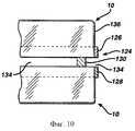
фиг.10 - вид сбоку пакетирующего устройства по фиг.9, расположенного между двумя стерилизационными контейнерами с целью пакетирования и разделения контейнеров;figure 10 is a side view of the packaging device of figure 9, located between two sterilization containers for packaging and separation of containers;
фиг.11 - перспективный вид дополнительного варианта осуществления пакетирующего устройства согласно настоящему изобретению; и11 is a perspective view of a further embodiment of a packaging device according to the present invention; and
фиг.12 - вид в плане обратной стороны крышки в дополнительном варианте осуществления согласно настоящему изобретению.12 is a plan view of the reverse side of the lid in a further embodiment according to the present invention.
Подробное описание изобретенияDETAILED DESCRIPTION OF THE INVENTION
На фиг.1 показан первый вариант осуществления стерилизации контейнера 10 в соответствии с настоящим изобретением. Контейнер 10 состоит из лотка 12, подставки 14 и крышки 16. Лоток 12 содержит прямоугольное основание 18, от которого вытянуты кверху две противолежащие боковые стенки 20 и две противолежащие торцевые стенки 22. Углы 24, образованные между боковыми 20 и торцевыми стенками 22, закруглены для придания приятного внешнего вида, повышения прочности и сглаживания острых кромок, которые могут нарушить целостность защитных резиновых перчаток (не показанных) оперирующего хирурга. Буртик 26 между основанием 18 и боковыми и торцевыми стенками 20 и 22 также усиливает прочность лотка 12.1 shows a first embodiment for sterilizing a
Основание 18 имеет множество дренажных ячеек 28, при этом каждая ячейка состоит из наклоненной книзу поверхности 30, заканчивающейся в дренажном отверстии 32. Наклонные поверхности 30 смежных дренажных ячеек 28 пересекаются с образованием гребней 34. Желательно, чтобы гребни 34 образовывали отчетливые линии или другие особенности в противоположность скругленным поверхностям раздела между смежными наклонными поверхностями 30. В этом случае минимизируются площади поверхностей гребней 34, которые поддерживают подставку 14, вследствие чего уменьшается площадь соприкосновения между основанием 18 и подставкой 14. Этим создается небольшое пространство, в котором можно улавливать конденсат или другое жидкое вещество. Подставка 14 имеет множество отверстий 38 подставки и множество вытянутых кверху шипов 36 для фиксации медицинских инструментов (не показанных), стерилизуемых внутри контейнера 10. Отверстия 38 в подставке 14 совмещены с дренажными отверстиями 32, проходящими сквозь основание 18 лотка. Предпочтительно изготавливать подставку 14 из силикона или другого эластомера, который устойчив при высокой температуре, связанной с паровой стерилизацией, и также противостоит химическому воздействию пероксида водорода, этиленоксида или других химических стерилизаторов или их исходных веществ, в частности стерилизаторов оксидирующего типа. Кроме того, материал подставки 14 не должен поглощать такие химические стерилизаторы или химически воздействовать с ними.The
Вытянутые кверху шипы 36 могут иметь различную форму. Например, они могут сужаться кверху или могут иметь постоянный диаметр. Кончик может быть плоским, скругленным или изогнутым по радиусу. Они (шипы) могут быть относительно мягкими или могут быть жесткими. Общее число шипов 36 и их шаг также может варьироваться. Такие подставки известны из уровня техники, а специалистам, практикующим в данной области техники, хорошо известно, как изменять их конструктивные параметры, чтобы достичь желаемого наибольшего эффекта.The
Крышка 16 контейнера имеет множество отверстий 40 крышки для содействия прохождению стерилизующих паров. Отверстия 40 крышки могут быть совмещены с дренажными отверстиями в лотке 12, но необходимости в таком совмещении нет. Кроме того, крышка 16 содержит ниспадающие боковые стенки 42 и торцевые стенки 44.The
Теперь обратимся дополнительно к фиг.2, на которой лоток 12 и крышка 16 имеют такие размеры, что торцевые стенки лотка или боковые стенки и торцевые стенки 20 и 22 точно пригнаны внутри боковых стенок и торцевых стенок 42 и 44 крышки. Предпочтительно, чтобы запорный механизм 46 был образован как одно целое в лотке 12 и крышке 16. Каждая из торцевых стенок 22 основания имеет углубленную часть 48. Пара U-образных вырезов 50 в каждой углубленной части 48 задает гибкую лапку 52. Верхний удлиненный конец 54 каждой лапки 52 имеет скошенную криволинейную поверхность 56 и фиксирующий выступ 58. Углубленные части 60 в крышке 16 совмещены с углублениями 48 в торцевых стенках и имеют прорезь 62 и фиксирующий выступ 64. Для фиксации запорного механизма 46 криволинейную поверхность 56 на каждой лапке 52 вводят в соответствующую прорезь 62 в крышке 16 и продвигают поверх фиксирующего выступа 64 до тех пор, пока фиксирующий выступ 58 на лапке 52 не войдет с щелчком в зацепление с фиксирующим выступом 64. Приложенное рукой давление на лапку 52, направленное внутрь, приводит к разъединению фиксирующих выступов 58 и 64 и к расцеплению запорного механизма 46.Now let us turn further to FIG. 2, in which the
Для усиления потока стерилизующих газов, проходящих через контейнер 10, каждая из боковых стенок 20 лотка и боковых стенок 22 крышки имеет несколько неглубоких вырезанных частей 66. Как показано на фиг.2, когда крышка 16 и лоток 12 взаимосвязаны, их вырезанные части 66 совмещаются друг с другом с образованием в контейнере 10 ограниченных щелевидных отверстий 68. Это усиливает поток стерилизующих газов, проходящих через контейнер 10.To enhance the flow of sterilizing gases passing through the
Обратимся к фиг.3, на которой показаны четыре бобышки 70, предусмотренные внутри крышки 16 для образования промежутка между крышкой 16 и лотком 12, посредством которого минимизируется площадь поверхности соприкосновения между ними, которая может блокировать поток газа или жидкости или которая может улавливать конденсат или другой жидкий материал.Referring to FIG. 3, there are four
Фиг.4 иллюстрирует улучшенные дренажные характеристики настоящего изобретения. Гребни 34 на основании 18 поддерживают гибкую подставку 14. Конденсат или другая жидкость, которая проходит между подставкой 14 и основанием 18, попадает внутрь одной из дренажных ячеек 28. Небольшая поверхность 71 соприкосновения, образующаяся между гребнями 34 и подставкой 14, предотвращает улавливание конденсата или других жидкостей между поверхностями основания 18 и подставки 14. Наклоненные книзу поверхности 30 дренажных ячеек 28 способствуют продвижению любого конденсата или других жидкостей по направлению к дренажным отверстиям 32. Затем конденсат физически выводится из контейнера 10. Необходимо обращать особое внимание на поддерживающие характеристики гребней 34. Для силикона и других эластомеров, пригодных для изготовления подставки 14, характерна тенденция к существенному размягчению в условиях высокой температуры стерилизации. Соответственно это является решающим для нормального поддержания подставки 14.4 illustrates improved drainage characteristics of the present invention. The
Выбор материала лотка для стерилизации пероксидом водорода или химической стерилизации зависит от химической стойкости или инертности материала относительно стерилизатора или исходных веществ для химической плазмы. Для плазмохимических методов стерилизации, которые зависят от возбужденных свободных радикалов, инертность материала по отношению к исходному веществу плазмы является даже более критичной из-за низких концентраций исходного вещества, при которых в некоторых предпочтительных плазменных способах возможно образование плазмы. Материал лотка должен быть химически негативным по отношению к стерилизаторам или к исходным веществам для химической плазмы, чтобы не влиять на летальность биологических объектов в стерилизационной камере. Для упрощения эксплуатации материал должен быть также устойчивым к химическим и тепловым воздействиям во время процедуры очистки и дезактивации инструментов и лотков, которую обычно проводят в клинических условиях. В больницах обычно используют моечную машину/дезактивационную машину, работающую при температуре 132°С, а также моющие вещества и энзиматические средства для удаления органического вещества.The choice of tray material for hydrogen peroxide sterilization or chemical sterilization depends on the chemical resistance or inertness of the material relative to the sterilizer or the starting materials for chemical plasma. For plasma chemical sterilization methods that depend on excited free radicals, the inertness of the material with respect to the starting material of the plasma is even more critical due to the low concentrations of the starting material, in which plasma formation is possible in some preferred plasma methods. The material of the tray should be chemically negative with respect to sterilizers or to the starting substances for chemical plasma, so as not to affect the lethality of biological objects in the sterilization chamber. To simplify operation, the material must also be resistant to chemical and thermal influences during the cleaning and decontamination of tools and trays, which is usually carried out in a clinical setting. Hospitals typically use a washer / decontamination machine operating at 132 ° C, as well as detergents and enzymatic agents to remove organic matter.
Идеальный материал для лотка, кроме этого, должен быть совместимым с основными средствами стерилизации, используемыми в больницах и в аналогичных учреждениях, включая паровой стерилизатор, газовый на основе этиленоксида и стерилизатор на основе пероксида водорода. Примером плазменной стерилизации на основе пероксида водорода является система стерилизации STER-RAD, в которой плазма пероксида водорода используется для ликвидации микроорганизмов на медицинских инструментах. Следовательно, идеальный материал должен иметь адекватные термомеханические свойства, чтобы противостоять пару, иметь немного остатков этиленоксида после обработки и экстремально слабо взаимодействовать с Н2О2 или с другими окислительными стерилизаторами.The ideal tray material should also be compatible with the basic sterilization equipment used in hospitals and similar facilities, including a steam sterilizer, ethylene oxide gas sterilizer and hydrogen peroxide sterilizer. An example of a hydrogen peroxide plasma sterilization is the STER-RAD sterilization system, in which hydrogen peroxide plasma is used to eliminate microorganisms in medical instruments. Therefore, an ideal material should have adequate thermomechanical properties to resist steam, have few residues of ethylene oxide after processing, and interact extremely weakly with H2 O2 or other oxidizing sterilizers.
Было тщательно исследовано и испытано много материалов, чтобы выявить материалы, пригодные для таких изменяющихся и экстремальных условий эксплуатации. В результате исследований было обнаружено, что предпочтительными материалами должны быть чистые (неармированные) и армированные жидкокристаллические полимеры на основе полиэфира, чистые и армированные полиэфиры и армированный полипропилен. Наиболее предпочтительным материалом является чистый или армированный полиэфирный жидкокристаллический полимер или его смесь с вышеупомянутыми полимерами. Примером выпускаемого промышленностью пригодного жидкокристаллического полимера является семейство VectraR, производимое корпорацией Hoechst Celenese Corporation.Many materials have been thoroughly researched and tested to identify materials suitable for such changing and extreme operating conditions. As a result of studies, it was found that the preferred materials should be pure (unreinforced) and reinforced polyester-based liquid crystal polymers, pure and reinforced polyesters, and reinforced polypropylene. The most preferred material is a pure or reinforced polyester liquid crystal polymer or a mixture thereof with the aforementioned polymers. An example of a commercially available suitable liquid crystal polymer is the VectraR family manufactured by Hoechst Celenese Corporation.
В пределах каждой группы семейства существуют предпочтительные химические структуры, с армированием и без него, которые могут рассматриваться как материалы лотка.Within each family group, there are preferred chemical structures, with and without reinforcement, that can be considered tray materials.
I. Армированный полипропилен, особенно армированный карбонатом кальция или стекловолокном, обеспечивает химическую инертность и структурные свойства, требуемые для стерилизации различного вида.I. Reinforced polypropylene, especially reinforced with calcium carbonate or fiberglass, provides the chemical inertness and structural properties required for various types of sterilization.
II. Полимеры полиэфирного типа, имеющие разнообразные базовые структуры, среди которых:II. Polyester-type polymers having a variety of basic structures, including:
1. Полиэтилентерефталат со следующей химической структурой:1. Polyethylene terephthalate with the following chemical structure:

2. Полибутилентерефталат, имеющий химическую структуру2. Polybutylene terephthalate having a chemical structure

3. Поликлогексилентерефталат со следующей химической структурой:3. Polyclohexylene terephthalate with the following chemical structure:

Полициклогексилентерефталат можно получить от компании Eastman Chemical Company под торговым названием Ektar с разнообразными немодифицированными и модифицированными структурами. Модификации могут содержать кислоты и гликольные структуры.Polycyclohexylene terephthalate can be obtained from Eastman Chemical Company under the trade name Ektar with a variety of unmodified and modified structures. Modifications may contain acids and glycol structures.
Среди семейства полиэфиров структура полиэтилентерефталата является предпочтительной. Наиболее предпочтительной формой является армированный стекловолокном полиэтилентерефталат. Армирование волокном обеспечивает конструкционную прочность в режиме стерилизации паром и, предпочтительно, для способов окислительной химической стерилизации паром или плазмой.Among the family of polyesters, the structure of polyethylene terephthalate is preferred. The most preferred form is fiberglass reinforced polyethylene terephthalate. Fiber reinforcement provides structural strength in the steam sterilization mode and, preferably, for methods of oxidative chemical sterilization with steam or plasma.
III. Жидкокристаллические полимеры, для которых характерны четыре основные видоизменения структуры:III. Liquid crystalline polymers, which are characterized by four basic structural modifications:
1. Полибензоатнафталат1. Polybenzoate naphthalate

Примером является выпускаемый корпорацией Hoechst Celanese Corporation продукт под торговым названием VECTRAR СЕРИЙ А и С.An example is a product sold by the Hoechst Celanese Corporation under the trade name VECTRAR SERIES A and C.
2. Полибензоат-терефталат-бис-феноизофталат2. Polybenzoate-terephthalate-bis-phenoisophthalate

Примером является имеющийся на рынке под торговым названием продукт XydarR, выпускаемый фирмой Amoco Performance Products.An example is the XydarR product commercially available from Amoco Performance Products.
3. Полибензоат-терефталат-этиленгликоль3. Polybenzoate-terephthalate-ethylene glycol

Примером является продукт под торговыми названиями X7G и Х7Н, выпускаемый компанией Eastman Chemical Company.An example is a product under the trade names X7G and X7H manufactured by Eastman Chemical Company.
4. Полинафталат-аминотерефталат4. Polynaphthalate-aminoterephthalate

Примером является продукт под торговым названием VestraR серии В, выпускаемый корпорацией Hoechst Celenese Corporation.An example is a product under the trade name VestraR Series B manufactured by Hoechst Celenese Corporation.
Наиболее предпочтительные структуры представляют собой полностью полиэфирные ароматические жидкокристаллические полимеры, которыми являются полибензоатнафталат и полибензоат-терефталат-бис-фенолизофталат. Вследствие конструкционной прочности этого семейства материалов предпочтительны как чистые, так и армированные сорта. Наиболее предпочтительными армирующими наполнителями являются стеклянные или минеральные волокна или фторполимеры в порошках.Most preferred structures are fully polyester aromatic liquid crystal polymers, which are polybenzoate naphthalate and polybenzoate terephthalate bis phenolisophthalate. Due to the structural strength of this family of materials, both pure and reinforced grades are preferred. The most preferred reinforcing agents are glass or mineral fibers or fluoropolymers in powders.
Характеристики материалов в среде пероксида водорода являются особенно важными. Для различных материалов были исследованы две тенденции, заключающиеся в поглощении пероксида водорода и в разложении пероксида водорода. В приведенной ниже табл. 1 показаны результаты для некоторых наиболее важных материалов.The characteristics of materials in a hydrogen peroxide environment are particularly important. For various materials, two trends were investigated, which consisted in the absorption of hydrogen peroxide and the decomposition of hydrogen peroxide. In the table below 1 shows the results for some of the most important materials.

Другое исследование было проведено для оценки совместимости материалов лотка с имитированными циклами стерилизации плазмой пероксида водорода и мойки/дезактивации, которые включают чередующиеся циклы стерилизации плазмой пероксида водорода и мойки/дезактивации и погружение в энзиматический раствор. Образцы сравнивались при деформациях растяжения 0,5 и 0,75%. В нижеследующей табл. 2 показаны результаты этой оценки.Another study was conducted to evaluate the compatibility of tray materials with simulated hydrogen peroxide plasma sterilization and washing / decontamination cycles, which include alternating hydrogen peroxide plasma sterilization and washing / decontamination cycles and immersion in an enzymatic solution. Samples were compared at tensile strains of 0.5 and 0.75%. In the following table. 2 shows the results of this assessment.

Кроме использования химически инертного материала имеются другие управляемые характеристики стерилизационных лотков или контейеров, способствующие снижению взаимодействия со стерилизационной средой и повышению устойчивости и используемым в больницах очищающим химикатам. Взаимодействие материала лотка со стерилизаторами или с исходными веществами для химической плазмы снижает содержание стерилизатора или исходного вещества для химической плазмы в паровой фазе, что влияет на летальность биологических объектов. Устойчивость к используемым в больницах химикатам увеличивает ожидаемый срок службы изделия. Поверхность стерилизационного лотка должна быть гладкой настолько, насколько это возможно, чтобы снизить отношение площадь поверхности/объем. Поскольку химическое и физическое взаимодействия со стерилизаторами или с исходными веществами для химической плазмы, как и деструкция материала, являются функцией отношения площадь поверхности/объем, сглаженные поверхности будут уменьшать скорость этих взаимодействий.In addition to the use of chemically inert material, there are other controllable characteristics of sterilization trays or containers that help to reduce interaction with the sterilization medium and increase stability and cleaning chemicals used in hospitals. The interaction of the tray material with sterilizers or with the starting materials for chemical plasma reduces the content of the sterilizer or the starting substance for chemical plasma in the vapor phase, which affects the lethality of biological objects. Resistance to chemicals used in hospitals increases the expected life of the product. The surface of the sterilization tray should be as smooth as possible to reduce the surface area / volume ratio. Since the chemical and physical interactions with sterilizers or with the starting materials for chemical plasma, as well as the destruction of the material, are a function of the surface area / volume ratio, smoothed surfaces will reduce the speed of these interactions.
Второй характеристикой, которую слудует регулировать, является толщина стенок. Толщина стенок является существенной для конструкционной прочности лотка или контейнера. Для стерилизационного лотка или контейнера, работающего в среде окислительных паров химикатов или химической плазмы, часто при пониженном давлении и небольшой концентрации, конденсация химического стерилизатора или исходного вещества для химической плазмы должна быть минимизирована. Конденсация есть функция тепловой массы и характеристик теплопередачи лотка или контейнера, и она может уменьшить количество стерилизатора или исходного вещества для химической плазмы в паровой фазе и таким образом повлиять на летальность биологических объектов.The second characteristic to be regulated is wall thickness. The wall thickness is essential for the structural strength of the tray or container. For a sterilization tray or container operating in an environment of oxidizing vapors of chemicals or chemical plasma, often under reduced pressure and low concentration, condensation of the chemical sterilizer or chemical plasma source material should be minimized. Condensation is a function of the heat mass and heat transfer characteristics of the tray or container, and it can reduce the amount of sterilizer or starting material for chemical plasma in the vapor phase and thus affect the lethality of biological objects.
Для минимизации тепловой массы и улучшения характеристик теплопередачи толщина стенок лотка или контейнеров должна быть минимизирована.To minimize heat mass and improve heat transfer characteristics, the wall thickness of the tray or containers should be minimized.
Поэтому следующие материалы являются предпочтительными для изготовления лотка 12 и крышки 16.Therefore, the following materials are preferred for the manufacture of the
I. Армированный полипропилен. Армированный полипропилен, особенно в случае армирования карбонатом кальция или стекловолокном, обеспечивает термомеханическую конструкционную целостность, необходимую для различных видов стерилизации.I. Reinforced polypropylene. Reinforced polypropylene, especially in the case of reinforcement with calcium carbonate or fiberglass, provides the thermomechanical structural integrity necessary for various types of sterilization.
II. Чистый или армированный полиэфир. Из семейства полиэфиров предпочтительна структура полиэтилентерефталата. Наиболее предпочтительной формой является армированный стеклом полиэтилентерефталат. Волоконное армирование обеспечивает конструкционную прочность, необходимую для режима стерилизации паром, и позволяет иметь тонкостенную конструкцию, которая предпочтительна в способе окислительной химической стерилизации паром.II. Pure or reinforced polyester. Of the family of polyesters, a polyethylene terephthalate structure is preferred. The most preferred form is glass reinforced polyethylene terephthalate. Fiber reinforcement provides the structural strength necessary for the steam sterilization mode, and allows you to have a thin-walled structure, which is preferred in the method of oxidative chemical steam sterilization.
III. Чистый или армированный жидкокристаллический полимер и/или смесь вышеуказанных материалов. Наиболее предпочтительны структуры полиэфирного полностью ароматического жидкокристаллического полимера, которые могут иметь химическое строение полибензоатнафталата или полибензоат-терефталат-бис-фенолизофталата. Из-за термомеханической прочности этого семейства материалов предпочтительны как чистые, так и армированные сорта. К числу наиболее предпочтительных армирующих групп относятся стеклянные и минеральные волокна.III. A pure or reinforced liquid crystal polymer and / or a mixture of the above materials. Most preferred are the structures of the polyester all-aromatic liquid crystal polymer, which may have the chemical structure of polybenzoate naphthalate or polybenzoate terephthalate bis-phenolisophthalate. Due to the thermomechanical strength of this family of materials, both pure and reinforced grades are preferred. Among the most preferred reinforcing groups are glass and mineral fibers.
IV. Смесь или сплав жидкокристаллических полимеров и веществ I или II из указанных выше.IV. A mixture or alloy of liquid crystal polymers and substances I or II of the above.
На фиг.5 и 6 показан второй вариант осуществления стерилизационного контейнера согласно изобретению. Контейнер 72 содержит лоток 74, крышку 76 и подставку (не показанную), аналогичные имевшимся в предыдущем варианте. Однако он снабжен иным запорным механизмом 78.5 and 6 show a second embodiment of a sterilization container according to the invention. The
Крышка 76 имеет верхнюю стенку 80 с проемом, а также связанные с ней боковые и торцевые стенки 82 и 84. В углубленной части 88 каждой торцевой стенки 84 крышки 76 имеется запорный элемент 86, образованный формовкой как одно целое. Пара торсионных стержней 80 проходит внутри углубленной части 88 от ее противоположных боковых стенок 92, чтобы поддерживать с возможностью поворота запорный элемент 86. Как лучше показано на фиг.6, торсионные стержни 90 отклоняют запорный элемент 86 в устойчивое положение зацепления и допускают ограниченный поворот от положения зацепления.The
Выемка 94 в каждой торцевой стенке 96 лотка 74 образует поверхность 98 зацепления. Выступ 100, выдающийся из нижней части 102 запорного элемента 86, входит в контакт с поверхностью 98 зацепления на лотке 74, чтобы посредством этого надежно удержать крышку 76 на лотке 74. Нажатие пальцем на приводную поверхность 104 на верхней части 106 запорного элемента 86 приводит к повороту запорного элемента 86 вокруг торсионных стержней 90 с освобождением поверхности 98 зацепления от выступа 100 и с отцеплением вследствие этого крышки 76 от лотка 74. Когда давление на приводную поверхность 104 прекращается, торсионные стержни 90 возвращают запорный элемент 86 в устойчивое положение зацепления.A
Все кромки и поверхности запорного элемента 86 закруглены и сглажены, особенно те, которые находятся на части 108 запорного элемента, обращенной наружу от углубления 88. Исключением является только выступ 100, находящийся на той части 109 запорного элемента, которая обращена внутрь лотка 74, вследствие чего отсутствуют острые кромки или поверхности, за которые пользователь может зацепить защитные перчатки (не показанные) и разорвать их. Все части запорного механизма 78 изготовлены формовкой как одно целое либо с лотком 74, либо с крышкой 76, посредством чего снижается стоимость изготовления и сборки. Конечно, местонахождение запорного механизма 78 может быть иным, таким, когда запорный элемент 86 образуют на лотке 74. Кроме того, крышку 76 можно приспособить так, чтобы она поворачивалась вокруг шарнира (не показанного) и, конечно, можно не образовывать запорный механизм 78 в торцевой стенке 84, а можно располагать его на контейнере 72 в другом месте. Однако местонахождение, показанное на фиг.5, является особенно удобным.All edges and surfaces of the locking
На фиг.7 и 8 показан вариант конструкции лотка 110 согласно изобретению. Лоток 110 можно использовать совместно со стерилизационным контейнером согласно первому и второму вариантам осуществления, а его отличия заключаются, главным образом, в основании 112. Основание 112 содержит плоскую панель 114, имеющую множество отверстий 116. В дополнение к этому, ряд более крупных удлиненных отверстий 118 проходит сквозь панель 114, а вытянутые кверху выступы 120 окружают каждое из удлиненных отверстий 118. Выступы 120 поддерживают подставку 122 и придают дополнительную жесткость основанию 112 лотка. Отверстия 124 в подставке 122 совмещены с удлиненными отверстиями 118 в основании лотка, чтобы обеспечить путь эффективной диффузии для стерилизующих газов.7 and 8 show an embodiment of the
На фиг.9 показано пакетирующее устройство 124 для пакетирования стерилизационных контейнеров 10 во время процедуры стерилизации. Пакетирующее устройство 124 имеет прямоугольную форму и несколько большие размеры, чем стерилизационный контейнер 10 (не показанный на фиг.9). Оно имеет вертикальные боковые стенки 126 и вертикальные торцевые стенки 128. L-образный выступающий элемент 130 вытянут в горизонтальном направлении внутрь от каждого угла 132 пакетирующего устройства 124. Как показано на фиг.9 и 10, каждая из боковых стенок 126 и торцевых стенок 128 имеет удлиненные окна 134 с такими же вертикальными размерами, как у выступающего элемента 130, и поэтому, когда контейнеры 10 установлены с использованием пакетирующего устройства 124, поток стерилизующих газов, втекающих в отдельные контейнеры 10 и вытекающий из них, не задерживается пакетирующим устройством 124.9 shows a
На фиг.10 показаны два стерилизационных контейнера 10, при этом каждый из них обернут стерильным покровным материалом 136. Пакетирующее устройство 124 установлено поверх первого контейнера 10, причем выступающий элемент 130 лежит на контейнере 10. Второй контейнер 10 опирается на выступающий элемент 130. Оба контейнера 10 расположены с внутренней стороны боковых и торцевых стенок 126 и 128 пакетирующего устройства. Поэтому два контейнера 10 устанавливаются и отделяются друг от друга с обеспечением пути потока в их окрестности.Figure 10 shows two
На фиг.11 показан вариант осуществления пакетирующего устройства 138. Вместо окна 134 каждая из боковых и торцевых стенок 140 и 142 соответственно имеет небольшой вертикальный профиль, смещенный в вертикальном направлении от выступающего элемента 144, посредством которого обеспечивается путь потоку при пакетированных контейнерах (не показанных на фиг.11).11 shows an embodiment of a
Вертикальные ребра 146 на боковых и торцевых стенках 140 и 142 придают жесткость и сохраняют открытым путь потоку, когда пакетирующее устройство помещено рядом с другим пакетирующим устройством или рядом с плоской поверхностью.The
На фиг.12 показан вариант осуществления крышки 150 согласно изобретению. Крышка 150 повторяет крышку 16 из фиг.1 и 3 с отдельными изменениями. Поэтому признаки, присущие крышке 16, будут обозначаться теми же номерами с добавлением одного штриха (’). В частности, крышка 150 отличается от крышки 16 чередованием круглых и удлиненных отверстий 152 и 154 соответственно. Кроме того, в каждом углу предусмотрен дополнительный буртик 156; эти буртики упрочняют крышку 150 и приподнимают крышку 150 над основанием 18 (не показанным на фиг.12) для улучшения циркуляции.12 shows an embodiment of a
Известны трудности, связанные с формированием жидкокристаллических полимеров. Одна особая проблема возникает, когда встречаются противоположные потоки расплавленного полимера. Такие зоны часто имеют пониженную прочность и поэтому желательно локализовать их на расстоянии от областей формованного изделия, которые будут подвергаться сильным напряжениям. В крышке 150 углубление 60’ образовано с помощью шпильки пресс-формы (не показанной). Потоки расплавленного полимера вокруг шпильки пресс-формы встречаются, чтобы замкнуться вокруг углубления 60’. Обычно эти потоки встречаются у фиксирующего выступа 64’. Однако эта зона подвергается сильным напряжениям. Поэтому крышку 150 выполняют с парой лидеров 158 потока, каждый из которых проходит от центральной зоны 160 крышки 150, где расплавленный полимер впрыскивается в процессе формования и подходит к внутреннему углу 162 соответствующих углублений 60’. Поэтому во время хода процесса формования расплавленный полимер протекает вокруг шпильки пресс-формы, а противоположные потоки встречаются у боковой части 164 углубления 60’.The difficulties associated with the formation of liquid crystal polymers are known. One particular problem arises when opposing flows of molten polymer are encountered. Such zones often have reduced strength and therefore it is desirable to localize them at a distance from areas of the molded product that will be subjected to strong stresses. In the
Хотя изобретение было подробно описано с подключением его конкретных вариантов осуществления, должно быть понятно, что это сделано с целью иллюстрации, а не ограничения, и что объем приложенной формулы изобретения должен толковаться настолько широко, насколько позволяет уровень техники.Although the invention has been described in detail with the inclusion of its specific embodiments, it should be understood that this was done for the purpose of illustration and not limitation, and that the scope of the appended claims should be construed as broadly as the prior art allows.
Claims (3)
Translated fromRussianApplications Claiming Priority (2)
| Application Number | Priority Date | Filing Date | Title |
|---|---|---|---|
| US08/672,802US6379631B1 (en) | 1996-06-28 | 1996-06-28 | Instrument sterilization container formed of a liquid crystal polymer |
| US08/672,802 | 1996-06-28 |
Publications (2)
| Publication Number | Publication Date |
|---|---|
| RU97111184A RU97111184A (en) | 1999-05-27 |
| RU2226405C2true RU2226405C2 (en) | 2004-04-10 |
Family
ID=24700061
Family Applications (1)
| Application Number | Title | Priority Date | Filing Date |
|---|---|---|---|
| RU97111184/14ARU2226405C2 (en) | 1996-06-28 | 1997-06-27 | Container manufactured from liquid crystal polymer for sterilizing instruments |
Country Status (18)
| Country | Link |
|---|---|
| US (4) | US6379631B1 (en) |
| EP (1) | EP0815876B1 (en) |
| JP (1) | JPH1066722A (en) |
| KR (1) | KR100699180B1 (en) |
| CN (1) | CN1135118C (en) |
| AT (1) | ATE251468T1 (en) |
| AU (1) | AU727245B2 (en) |
| BR (1) | BR9703802B1 (en) |
| CA (1) | CA2208927C (en) |
| DE (1) | DE69725389T2 (en) |
| DK (1) | DK0815876T3 (en) |
| IN (1) | IN191124B (en) |
| MY (1) | MY130947A (en) |
| NO (1) | NO312498B1 (en) |
| RU (1) | RU2226405C2 (en) |
| SG (1) | SG50859A1 (en) |
| TW (1) | TW413626B (en) |
| ZA (1) | ZA975766B (en) |
Cited By (4)
| Publication number | Priority date | Publication date | Assignee | Title |
|---|---|---|---|---|
| EA014731B1 (en)* | 2006-03-23 | 2011-02-28 | Биомедикал Текнолоджи Солюшнз, Инк. | SYSTEMS, DEVICES AND METHODS OF HEAT TREATMENT FOR COLLECTION AND REMOVAL OF INFECTIOUS AND MEDICAL WASTE |
| RU2589582C1 (en)* | 2012-06-08 | 2016-07-10 | Альфа Лаваль Корпорейт Аб | Plate heat exchanger |
| RU171409U1 (en)* | 2016-12-16 | 2017-05-30 | Федеральное государственное бюджетное образовательное учреждение высшего образования "Пермский государственный медицинский университет имени академика Е.А. Вагнера" Министерства здравоохранения Российской Федерации | Separator for storing biological preparations of teeth for the purpose of modeling artificial caries |
| RU2678997C2 (en)* | 2013-10-15 | 2019-02-05 | Анакаил Лимитед | Plasma treatment system for rigid containers |
Families Citing this family (59)
| Publication number | Priority date | Publication date | Assignee | Title |
|---|---|---|---|---|
| US6495100B1 (en)* | 1996-04-04 | 2002-12-17 | Ethicon, Inc. | Method for sterilizing devices in a container |
| US6379631B1 (en)* | 1996-06-28 | 2002-04-30 | Johnson & Johnson Medical, Inc. | Instrument sterilization container formed of a liquid crystal polymer |
| US6852279B2 (en)* | 2002-06-28 | 2005-02-08 | Ethicon, Inc. | Sterilization with temperature-controlled diffusion path |
| US7569180B2 (en)* | 2004-10-12 | 2009-08-04 | Ethicon, Inc. | Sterilization system and method and orifice inlet control apparatus therefor |
| DE10124252B4 (en)* | 2001-05-18 | 2005-12-15 | Aesculap Ag & Co. Kg | Screen basket for surgical instruments |
| SE522756C2 (en)* | 2001-06-13 | 2004-03-02 | Getinge Disinfection Ab | Disinfection chamber for use in a disinfecting device |
| US7049237B2 (en)* | 2001-12-21 | 2006-05-23 | Micron Technology, Inc. | Methods for planarization of Group VIII metal-containing surfaces using oxidizing gases |
| US7807100B2 (en)* | 2002-06-28 | 2010-10-05 | Ethicon, Inc. | Sterilization system and method with temperature-controlled condensing surface |
| US7201869B2 (en)* | 2002-06-28 | 2007-04-10 | Ethicon, Inc. | Sterilizer with restrictor |
| US20040062693A1 (en)* | 2002-09-30 | 2004-04-01 | Szu-Min Lin | Sterilization container with a sealable filtered opening |
| US7300637B2 (en)* | 2002-09-30 | 2007-11-27 | Ethicon, Inc. | Sterilization container kit |
| US20040071587A1 (en)* | 2002-10-11 | 2004-04-15 | Mcatarian Patrick F. | Quick setup decontamination stall |
| US20050042130A1 (en)* | 2003-08-22 | 2005-02-24 | Szu-Min Lin | Mist sterilization system |
| US20050095169A1 (en)* | 2003-10-31 | 2005-05-05 | Wu Su-Syin | Sterilization tray and mat |
| FR2862618B1 (en)* | 2003-11-24 | 2007-04-13 | Pierre Malek | TOOL DISCHARGE TOOL STORAGE DEVICE |
| US20050147777A1 (en)* | 2004-01-05 | 2005-07-07 | Fries Carolyn A. | Lightweight plastic laminate suitable for gas and moisture resistant environmental housings |
| US7713473B2 (en)* | 2005-06-30 | 2010-05-11 | Ethicon, Inc. | Sterilization system and vaporizer therefor |
| US7758825B2 (en)* | 2005-08-10 | 2010-07-20 | Cook Incorporated | Tray removal handle |
| JP2007054343A (en)* | 2005-08-25 | 2007-03-08 | Pentax Corp | Endoscope steam sterilization tray |
| US7544336B2 (en)* | 2005-11-07 | 2009-06-09 | Andrew Powell | Sterilization tray with base and elastomeric lid |
| DE102005057111A1 (en)* | 2005-11-28 | 2007-05-31 | Karl Storz Gmbh & Co. Kg | Device for blocking a tendon transplant |
| US20070231196A1 (en)* | 2006-03-31 | 2007-10-04 | Szu-Min Lin | Foam pretreatment for medical instruments |
| US20070228085A1 (en)* | 2006-03-31 | 2007-10-04 | Szu-Min Lin | Dispenser for delivering foam and mist |
| US20070231201A1 (en)* | 2006-03-31 | 2007-10-04 | Roberts Charles G | Method and system for prion inactivation |
| US20070259801A1 (en)* | 2006-03-31 | 2007-11-08 | Szu-Min Lin | Composition for a foam pretreatment for medical instruments |
| US20070231200A1 (en)* | 2006-03-31 | 2007-10-04 | Szu-Min Lin | Hydrogen peroxide foam treatment |
| US20070231198A1 (en)* | 2006-03-31 | 2007-10-04 | Szu-Min Lin | Hydrogen Peroxide Foam Treatment |
| US20070231202A1 (en)* | 2006-03-31 | 2007-10-04 | Roberts Charles G | method and system for prion inactivation |
| US7871581B1 (en)* | 2006-10-19 | 2011-01-18 | Patient Care Solutions, LLC | Medical instrument holding assembly and method for improved pre-sterilization cleaning using same |
| DE602007011266D1 (en)* | 2007-09-12 | 2011-01-27 | Datamars Sa | Manufacturing method for a miniature implantable transponder |
| US20100064948A1 (en)* | 2008-07-25 | 2010-03-18 | Tucker Holly S | Drawer Liner |
| EP2163219B1 (en)* | 2008-09-15 | 2012-04-11 | Straumann Holding AG | Cassette for storage of medical instruments |
| US8418872B2 (en) | 2010-12-21 | 2013-04-16 | Kimberly-Clark Worldwide, Inc. | Sterilization container with releasable and permanent lock |
| EP2654595A1 (en)* | 2010-12-23 | 2013-10-30 | Straumann Holding AG | Cassette for storage of medical instruments |
| US9028020B2 (en)* | 2011-03-11 | 2015-05-12 | Electrolux Home Products, Inc. | Stabilizing panel |
| USD666305S1 (en) | 2011-08-19 | 2012-08-28 | Life Technologies Corporation | Apparatus for docking and charging electrophoresis devices and portable electrophoresis system |
| CN112641960B (en) | 2011-12-28 | 2023-01-06 | 雅培制药有限公司 | Method and apparatus for reducing bio-entrainment using induction heating |
| US9463257B1 (en) | 2012-03-22 | 2016-10-11 | Integrated Medical Technologies, Inc. | Rapid heat transfer sterilization system for surgical instruments and devices |
| JP6385930B2 (en) | 2012-08-07 | 2018-09-05 | シカン・リミテッド | Containers for cleaning, sterilizing, transporting and sterilizing items |
| USD712065S1 (en)* | 2012-09-03 | 2014-08-26 | Hitachi High-Technologies Corporation | Organizer for liquid chromatograph analyzer |
| US20140077435A1 (en)* | 2012-09-14 | 2014-03-20 | Andrew Powell | Sterilization Base-Tray with Internal Frame and Integrated Latching and Intrument Retention System |
| US9687299B2 (en) | 2012-10-24 | 2017-06-27 | Symmetry Medical Manufacturing, Inc. | Light reflection and glare preventing medical instrument holding apparatus and related methods |
| US9610126B2 (en) | 2013-05-20 | 2017-04-04 | Practicon, Inc. | Flexible containers for use in sterilizing, storing, transporting, and presenting medical instruments |
| CN103391045B (en) | 2013-07-30 | 2015-11-25 | 浙江大学 | Oscillator on integrated circuit chip is adjusted in reviewing one's lessons by oneself of anti-process fluctuation |
| US9205989B1 (en)* | 2013-08-02 | 2015-12-08 | John M. Leslie | Chain mounted product capturing gripper construction |
| USD716964S1 (en)* | 2014-03-06 | 2014-11-04 | American Sterilizer Company | Cassette for steam sterilizer |
| AU2015256267B2 (en) | 2014-05-06 | 2017-08-10 | American Sterilizer Company | Sterilizer |
| US10071178B2 (en) | 2014-12-30 | 2018-09-11 | Safe-Decon, Inc. | Sealable decontamination holding vessel for isolating contaminated items |
| WO2016138482A1 (en)* | 2015-02-26 | 2016-09-01 | K&K Lukas LLC | Dry heat sanitizer and method of use |
| US20160303791A1 (en) | 2015-04-17 | 2016-10-20 | Symmetry Medical Manufacturing, Inc | System and Method for Sterilization of Medical Instruments within a Hydrogen Peroxide Sterilization Process |
| JP6796131B2 (en) | 2015-10-30 | 2020-12-02 | オーアンドエム ハリヤード インターナショナル アンリミテッド カンパニー | Sterilization packaging system |
| CN115002952B (en) | 2016-12-22 | 2025-04-29 | 雅培制药有限公司 | Induction heating system and control method for reducing biological carryover |
| AU2018342093B2 (en) | 2017-09-26 | 2023-09-07 | Stryker Corporation | System and method for wirelessly charging a medical device battery |
| US10668176B2 (en) | 2017-12-01 | 2020-06-02 | Asp Global Manufacturing Gmbh | Sterilization tray |
| US10814027B2 (en) | 2017-12-07 | 2020-10-27 | Asp Global Manufacturing Gmbh | Sterilization-assistance device |
| USD903901S1 (en) | 2017-12-12 | 2020-12-01 | Practicon, Inc. | Medical instruments tray |
| US10967084B2 (en) | 2017-12-15 | 2021-04-06 | Asp Global Manufacturing Gmbh | Flow restrictor |
| US11191859B2 (en) | 2017-12-29 | 2021-12-07 | Asp Global Manufacturing Gmbh | Sterilization tray |
| DE102018104938A1 (en) | 2018-03-05 | 2019-09-05 | Aesculap Ag | Sterilizing mesh tray with a corrugation or bulging or bulging forming sheet metal floor |
Citations (1)
| Publication number | Priority date | Publication date | Assignee | Title |
|---|---|---|---|---|
| US4704254A (en)* | 1984-11-05 | 1987-11-03 | Nichols Robert L | Filtered port suitable for medical sterilization containers and method or use thereof |
Family Cites Families (63)
| Publication number | Priority date | Publication date | Assignee | Title |
|---|---|---|---|---|
| US295075A (en)* | 1884-03-11 | stone | ||
| JPS54142271A (en)* | 1978-04-28 | 1979-11-06 | Kureha Chem Ind Co Ltd | Multi-layer blow molded article |
| JPS55131049A (en)* | 1979-04-02 | 1980-10-11 | Sumitomo Chem Co Ltd | Novel thermoplastic resin composition |
| ES248326Y (en)* | 1980-02-04 | 1981-01-01 | STACKABLE AND PALLETIZABLE SQUARE DRUM | |
| US4370369A (en)* | 1981-07-02 | 1983-01-25 | Composite Container Corporation | Heat-sealable sheet and container |
| DE3146349C2 (en)* | 1981-11-23 | 1983-12-15 | Georg Wagner KG, 8000 München | Sterilization container |
| US4468384A (en)* | 1982-01-05 | 1984-08-28 | The Research Foundation Of State University Of New York | Method for the inhibition of the replication of DNA viruses with 5-substituted 2-pyrimidinone nucleosides |
| US4468364A (en) | 1983-04-28 | 1984-08-28 | Celanese Corporation | Process for extruding thermotropic liquid crystalline polymers |
| US4541992A (en) | 1983-08-10 | 1985-09-17 | Hu-Friedy Manufacturing Co. | Apparatus for organizing, sterilizing, and maintaining medical/dental instruments |
| US4915913A (en)* | 1984-05-22 | 1990-04-10 | Genesis Medical Corporation | Medical sterilizer device with improved latch mechanism |
| US4617178A (en) | 1984-11-05 | 1986-10-14 | Nichols Robert L | Medical instrument sterilization container |
| US4900519A (en) | 1984-11-05 | 1990-02-13 | Nichols Robert L | Medical instrument sterilization container |
| US5202098A (en) | 1984-11-05 | 1993-04-13 | Nichols Robert L | Medical instrument sterilization container with pressure induced positive drainage |
| US4716025A (en) | 1984-11-05 | 1987-12-29 | Nichols Robert L | Medical sterilization container with instrument tray |
| US4752453A (en) | 1984-11-05 | 1988-06-21 | Nichols Robert L | Medical instrument sterilization container with fluid filters |
| US5183643A (en) | 1984-11-05 | 1993-02-02 | Nichols Robert L | Medical instrument sterilization container |
| US4915918A (en) | 1984-11-05 | 1990-04-10 | Nichols Robert L | Medical instrument sterilization container |
| US4728504A (en) | 1984-11-05 | 1988-03-01 | Nichols Robert L | Stackable medical instrument sterilizer container |
| US5080874A (en) | 1984-11-05 | 1992-01-14 | Nichols Robert L | Medical instrument sterilization container |
| DE3442835C2 (en) | 1984-11-23 | 1987-02-19 | Bosch-Siemens Hausgeräte GmbH, 8000 München | Locking device for a hinged cover plate of a housing opening on a household appliance |
| US4783321A (en)* | 1984-12-18 | 1988-11-08 | Instrumed, Inc. | Sterlization container system |
| US4661326A (en)* | 1985-02-25 | 1987-04-28 | Herbert Schainholz | Sterilization container |
| USD295075S (en) | 1985-07-22 | 1988-04-05 | Hu-Friedy Manufacturing Co., Inc. | Combined instrument sterilization and storage cassette |
| US4854475A (en) | 1985-07-22 | 1989-08-08 | Hu-Friedy Manufacturing Co., Inc. | Instrument cassette |
| DE3544341C1 (en) | 1985-12-14 | 1987-06-04 | Aesculap Werke Ag | Sterilising vessel for surgical instruments |
| US4625885A (en) | 1986-03-20 | 1986-12-02 | Nichols Robert L | Controlled-release security band for sterilization container |
| US4798292A (en) | 1987-04-03 | 1989-01-17 | Biomedical Laser Industries | Sterilization, storage, and presentation container for surgical instruments |
| JPH01153453A (en)* | 1987-12-10 | 1989-06-15 | Toyo Seikan Kaisha Ltd | Pressure-and heat-resisting container and production thereof |
| CA1334469C (en) | 1988-03-03 | 1995-02-14 | Marvin Edward Sauers | Poly(aryl ether sulfones) with improved environmental stress-crack resistance and medical devices made therefrom |
| JP2790840B2 (en) | 1989-03-31 | 1998-08-27 | ダイセル化学工業株式会社 | Packaging materials for medical articles |
| US5352312A (en) | 1989-05-10 | 1994-10-04 | Thiokol Corporation | Method of insulating a rocket motor |
| US5124125A (en) | 1990-07-10 | 1992-06-23 | Brent David A | Method for processing infectious waste using microwaves |
| JP2971934B2 (en)* | 1990-10-17 | 1999-11-08 | ポリプラスチックス株式会社 | Manufacturing method of transparent heat-resistant container |
| DE69117672D1 (en)* | 1990-11-28 | 1996-04-11 | Matsushita Electric Industrial Co Ltd | Fiber optic coil and manufacturing process |
| US5098676B2 (en) | 1991-01-04 | 1997-11-25 | Poly Vac Inc | Sterilization and storage container tray |
| DE4103146C1 (en) | 1991-02-02 | 1992-03-26 | Richard Wolf Gmbh, 7134 Knittlingen, De | |
| US5227074A (en) | 1991-03-04 | 1993-07-13 | Monarch Products, Inc. | Filter for medical instrument sterilization containers and method for removing moisture and contaminants therefrom |
| US5324489A (en) | 1991-03-04 | 1994-06-28 | Johnson & Johnson Medical, Inc. | Medical instrument sterilization container with a contaminant plug |
| US5283114A (en) | 1991-04-25 | 1994-02-01 | Edison Polymer Innovation Corporation | Wholly aromatic polyester fiber-reinforced polystyrene-poly(phenylene oxide) blend |
| US5215726A (en) | 1991-07-17 | 1993-06-01 | Hu-Friedy Mfg. Co., Inc. | Two-tiered sterilization and storage cassette |
| US5165539A (en)* | 1991-12-19 | 1992-11-24 | Kimberly-Clark Corporation | Surgical instrument transport tray |
| US5384103A (en)* | 1992-03-17 | 1995-01-24 | Micromedics, Inc. | Instrument tray |
| US5346075A (en) | 1992-04-17 | 1994-09-13 | Johnson & Johnson Medical, Inc. | Apparatus and method for holding a medical instrument |
| US5346677A (en) | 1992-09-04 | 1994-09-13 | Risk William B | Instrument cassette |
| JP3249200B2 (en) | 1992-09-16 | 2002-01-21 | 株式会社リコー | Curl straightener |
| US5281400A (en)* | 1992-09-30 | 1994-01-25 | Carr Metal Products | Plastic autoclave tray and lid combination |
| SI9300468A (en) | 1992-10-14 | 1994-06-30 | Hoffmann La Roche | Injectable composition for the sustained release of biologically active compounds |
| US5356017A (en)* | 1992-10-28 | 1994-10-18 | Aptargroup, Inc. | Child resistant closure with recessed latch |
| US5451379A (en)* | 1992-12-07 | 1995-09-19 | Bowlin, Jr.; Eugene F. | Sterilization cassette for dental instruments |
| US5350059A (en) | 1993-02-02 | 1994-09-27 | Minnesota Mining And Manufacturing Company | Dental dispensing system |
| US5377860A (en)* | 1993-09-14 | 1995-01-03 | James River Corporation Of Virginia | Double seal food container |
| US5407648A (en) | 1993-09-29 | 1995-04-18 | Paragon Group Of Plastics Companies, Inc. | Combination sterilization tray and mat |
| US5518115A (en)* | 1994-09-22 | 1996-05-21 | Poly Vac Incorporated | Sterilization and storage container tray including grommets |
| US5525314A (en)* | 1994-09-26 | 1996-06-11 | Bausch & Lomb Incorporated | Surgical tool container system |
| AU3458095A (en) | 1994-11-03 | 1996-05-09 | Johnson & Johnson Medical, Inc. | Liquid repellent sterilizable material |
| US5490975A (en)* | 1994-12-14 | 1996-02-13 | Poly-Vac Incorporated | Sterilization and storage container tray |
| JP2716683B2 (en)* | 1995-08-11 | 1998-02-18 | 株式会社クラレ | Heat resistant polyester thermoformed container |
| US5730311A (en)* | 1995-11-13 | 1998-03-24 | Tenneco Packaging Inc. | Controlled atmosphere package |
| US6572819B1 (en)* | 1996-06-28 | 2003-06-03 | Johnson & Johnson Medical, Inc. | Instrument sterilization container having improved drainage and support for an instrument mat |
| US6264902B1 (en)* | 1996-06-28 | 2001-07-24 | Johnson & Johnson Medical, Inc. | Instrument sterilization container having an improved latching mechanism |
| US6379631B1 (en) | 1996-06-28 | 2002-04-30 | Johnson & Johnson Medical, Inc. | Instrument sterilization container formed of a liquid crystal polymer |
| US5896987A (en)* | 1998-03-17 | 1999-04-27 | Sterilization Cassette Systems, Inc. | Instrument cassette having stacking feature |
| US6164738A (en)* | 1999-01-29 | 2000-12-26 | Poly Vac, Inc. | Stacking sterilizing tray system |
- 1996
- 1996-06-28USUS08/672,802patent/US6379631B1/ennot_activeExpired - Lifetime
- 1997
- 1997-06-26CACA002208927Apatent/CA2208927C/ennot_activeExpired - Lifetime
- 1997-06-26ININ1226CA1997patent/IN191124B/enunknown
- 1997-06-26SGSG1997002202Apatent/SG50859A1/enunknown
- 1997-06-26AUAU27543/97Apatent/AU727245B2/ennot_activeExpired
- 1997-06-27EPEP97304655Apatent/EP0815876B1/ennot_activeExpired - Lifetime
- 1997-06-27RURU97111184/14Apatent/RU2226405C2/enactive
- 1997-06-27JPJP9208253Apatent/JPH1066722A/enactivePending
- 1997-06-27NONO19973011Apatent/NO312498B1/ennot_activeIP Right Cessation
- 1997-06-27DKDK97304655Tpatent/DK0815876T3/enactive
- 1997-06-27ZAZA975766Apatent/ZA975766B/enunknown
- 1997-06-27MYMYPI97002915Apatent/MY130947A/enunknown
- 1997-06-27DEDE69725389Tpatent/DE69725389T2/ennot_activeExpired - Lifetime
- 1997-06-27ATAT97304655Tpatent/ATE251468T1/ennot_activeIP Right Cessation
- 1997-06-27KRKR1019970031034Apatent/KR100699180B1/ennot_activeExpired - Lifetime
- 1997-06-28CNCNB971178151Apatent/CN1135118C/ennot_activeExpired - Lifetime
- 1997-06-30BRBRPI9703802-4Apatent/BR9703802B1/ennot_activeIP Right Cessation
- 1997-07-24TWTW086109215Apatent/TW413626B/ennot_activeIP Right Cessation
- 2002
- 2002-04-02USUS10/114,212patent/US6692693B2/ennot_activeExpired - Lifetime
- 2003
- 2003-02-28USUS10/376,939patent/US6759017B2/ennot_activeExpired - Lifetime
- 2003-02-28USUS10/376,993patent/US20030211023A1/ennot_activeAbandoned
Patent Citations (1)
| Publication number | Priority date | Publication date | Assignee | Title |
|---|---|---|---|---|
| US4704254A (en)* | 1984-11-05 | 1987-11-03 | Nichols Robert L | Filtered port suitable for medical sterilization containers and method or use thereof |
Cited By (4)
| Publication number | Priority date | Publication date | Assignee | Title |
|---|---|---|---|---|
| EA014731B1 (en)* | 2006-03-23 | 2011-02-28 | Биомедикал Текнолоджи Солюшнз, Инк. | SYSTEMS, DEVICES AND METHODS OF HEAT TREATMENT FOR COLLECTION AND REMOVAL OF INFECTIOUS AND MEDICAL WASTE |
| RU2589582C1 (en)* | 2012-06-08 | 2016-07-10 | Альфа Лаваль Корпорейт Аб | Plate heat exchanger |
| RU2678997C2 (en)* | 2013-10-15 | 2019-02-05 | Анакаил Лимитед | Plasma treatment system for rigid containers |
| RU171409U1 (en)* | 2016-12-16 | 2017-05-30 | Федеральное государственное бюджетное образовательное учреждение высшего образования "Пермский государственный медицинский университет имени академика Е.А. Вагнера" Министерства здравоохранения Российской Федерации | Separator for storing biological preparations of teeth for the purpose of modeling artificial caries |
Also Published As
| Publication number | Publication date |
|---|---|
| EP0815876B1 (en) | 2003-10-08 |
| DE69725389D1 (en) | 2003-11-13 |
| NO312498B1 (en) | 2002-05-21 |
| MY130947A (en) | 2007-07-31 |
| AU2754397A (en) | 1998-01-15 |
| NO973011D0 (en) | 1997-06-27 |
| EP0815876A3 (en) | 1999-12-15 |
| CN1182624A (en) | 1998-05-27 |
| DE69725389T2 (en) | 2005-11-03 |
| IN191124B (en) | 2003-09-27 |
| DK0815876T3 (en) | 2004-01-26 |
| TW413626B (en) | 2000-12-01 |
| US6692693B2 (en) | 2004-02-17 |
| KR100699180B1 (en) | 2007-07-09 |
| CA2208927C (en) | 2005-11-22 |
| US20020192108A1 (en) | 2002-12-19 |
| ATE251468T1 (en) | 2003-10-15 |
| US20030211023A1 (en) | 2003-11-13 |
| US6379631B1 (en) | 2002-04-30 |
| BR9703802A (en) | 1998-11-10 |
| BR9703802B1 (en) | 2009-01-13 |
| US20030185731A1 (en) | 2003-10-02 |
| KR980000472A (en) | 1998-03-30 |
| CN1135118C (en) | 2004-01-21 |
| EP0815876A2 (en) | 1998-01-07 |
| MX9704965A (en) | 1998-05-31 |
| SG50859A1 (en) | 1998-07-20 |
| US6759017B2 (en) | 2004-07-06 |
| ZA975766B (en) | 1998-12-28 |
| CA2208927A1 (en) | 1997-12-28 |
| NO973011L (en) | 1997-12-29 |
| AU727245B2 (en) | 2000-12-07 |
| JPH1066722A (en) | 1998-03-10 |
Similar Documents
| Publication | Publication Date | Title |
|---|---|---|
| RU2226405C2 (en) | Container manufactured from liquid crystal polymer for sterilizing instruments | |
| CA2208862C (en) | Instrument sterilization container having improved drainage and support for an instrument mat | |
| EP0815875B1 (en) | Instrument sterilization container having a latching mechanism | |
| RU97111184A (en) | TOOL STERILIZATION CONTAINER, PERFORMED FROM LIQUID CRYSTAL POLYMER | |
| KR0120398B1 (en) | Barrier label | |
| JPH1066722A5 (en) | ||
| JP4237489B2 (en) | Transparent medical packaging | |
| Topala et al. | Influence of plasma treatments on the hemocompatibility of PET and PET+ TiO2 films | |
| MXPA97004965A (en) | Instrument sterilization container formed of a liquid crystal polymer |