RU2222858C1 - Device for remote monitoring of overhead power transmission line conductors for condition (alternatives) - Google Patents
Device for remote monitoring of overhead power transmission line conductors for condition (alternatives)Download PDFInfo
- Publication number
- RU2222858C1 RU2222858C1RU2002129160/09ARU2002129160ARU2222858C1RU 2222858 C1RU2222858 C1RU 2222858C1RU 2002129160/09 ARU2002129160/09 ARU 2002129160/09ARU 2002129160 ARU2002129160 ARU 2002129160ARU 2222858 C1RU2222858 C1RU 2222858C1
- Authority
- RU
- Russia
- Prior art keywords
- wire
- unit
- data
- signals
- receiving
- Prior art date
Links
Images
Classifications
- G—PHYSICS
- G01—MEASURING; TESTING
- G01R—MEASURING ELECTRIC VARIABLES; MEASURING MAGNETIC VARIABLES
- G01R15/00—Details of measuring arrangements of the types provided for in groups G01R17/00 - G01R29/00, G01R33/00 - G01R33/26 or G01R35/00
- G01R15/14—Adaptations providing voltage or current isolation, e.g. for high-voltage or high-current networks
- G01R15/142—Arrangements for simultaneous measurements of several parameters employing techniques covered by groups G01R15/14 - G01R15/26
- H—ELECTRICITY
- H02—GENERATION; CONVERSION OR DISTRIBUTION OF ELECTRIC POWER
- H02J—CIRCUIT ARRANGEMENTS OR SYSTEMS FOR SUPPLYING OR DISTRIBUTING ELECTRIC POWER; SYSTEMS FOR STORING ELECTRIC ENERGY
- H02J13/00—Circuit arrangements for providing remote indication of network conditions, e.g. an instantaneous record of the open or closed condition of each circuitbreaker in the network; Circuit arrangements for providing remote control of switching means in a power distribution network, e.g. switching in and out of current consumers by using a pulse code signal carried by the network
- H02J13/00002—Circuit arrangements for providing remote indication of network conditions, e.g. an instantaneous record of the open or closed condition of each circuitbreaker in the network; Circuit arrangements for providing remote control of switching means in a power distribution network, e.g. switching in and out of current consumers by using a pulse code signal carried by the network characterised by monitoring
- H—ELECTRICITY
- H02—GENERATION; CONVERSION OR DISTRIBUTION OF ELECTRIC POWER
- H02J—CIRCUIT ARRANGEMENTS OR SYSTEMS FOR SUPPLYING OR DISTRIBUTING ELECTRIC POWER; SYSTEMS FOR STORING ELECTRIC ENERGY
- H02J13/00—Circuit arrangements for providing remote indication of network conditions, e.g. an instantaneous record of the open or closed condition of each circuitbreaker in the network; Circuit arrangements for providing remote control of switching means in a power distribution network, e.g. switching in and out of current consumers by using a pulse code signal carried by the network
- H02J13/00006—Circuit arrangements for providing remote indication of network conditions, e.g. an instantaneous record of the open or closed condition of each circuitbreaker in the network; Circuit arrangements for providing remote control of switching means in a power distribution network, e.g. switching in and out of current consumers by using a pulse code signal carried by the network characterised by information or instructions transport means between the monitoring, controlling or managing units and monitored, controlled or operated power network element or electrical equipment
- H02J13/00016—Circuit arrangements for providing remote indication of network conditions, e.g. an instantaneous record of the open or closed condition of each circuitbreaker in the network; Circuit arrangements for providing remote control of switching means in a power distribution network, e.g. switching in and out of current consumers by using a pulse code signal carried by the network characterised by information or instructions transport means between the monitoring, controlling or managing units and monitored, controlled or operated power network element or electrical equipment using a wired telecommunication network or a data transmission bus
- H02J13/00017—Circuit arrangements for providing remote indication of network conditions, e.g. an instantaneous record of the open or closed condition of each circuitbreaker in the network; Circuit arrangements for providing remote control of switching means in a power distribution network, e.g. switching in and out of current consumers by using a pulse code signal carried by the network characterised by information or instructions transport means between the monitoring, controlling or managing units and monitored, controlled or operated power network element or electrical equipment using a wired telecommunication network or a data transmission bus using optical fiber
- H—ELECTRICITY
- H02—GENERATION; CONVERSION OR DISTRIBUTION OF ELECTRIC POWER
- H02J—CIRCUIT ARRANGEMENTS OR SYSTEMS FOR SUPPLYING OR DISTRIBUTING ELECTRIC POWER; SYSTEMS FOR STORING ELECTRIC ENERGY
- H02J13/00—Circuit arrangements for providing remote indication of network conditions, e.g. an instantaneous record of the open or closed condition of each circuitbreaker in the network; Circuit arrangements for providing remote control of switching means in a power distribution network, e.g. switching in and out of current consumers by using a pulse code signal carried by the network
- H02J13/00006—Circuit arrangements for providing remote indication of network conditions, e.g. an instantaneous record of the open or closed condition of each circuitbreaker in the network; Circuit arrangements for providing remote control of switching means in a power distribution network, e.g. switching in and out of current consumers by using a pulse code signal carried by the network characterised by information or instructions transport means between the monitoring, controlling or managing units and monitored, controlled or operated power network element or electrical equipment
- H02J13/00022—Circuit arrangements for providing remote indication of network conditions, e.g. an instantaneous record of the open or closed condition of each circuitbreaker in the network; Circuit arrangements for providing remote control of switching means in a power distribution network, e.g. switching in and out of current consumers by using a pulse code signal carried by the network characterised by information or instructions transport means between the monitoring, controlling or managing units and monitored, controlled or operated power network element or electrical equipment using wireless data transmission
- H02J13/00024—Circuit arrangements for providing remote indication of network conditions, e.g. an instantaneous record of the open or closed condition of each circuitbreaker in the network; Circuit arrangements for providing remote control of switching means in a power distribution network, e.g. switching in and out of current consumers by using a pulse code signal carried by the network characterised by information or instructions transport means between the monitoring, controlling or managing units and monitored, controlled or operated power network element or electrical equipment using wireless data transmission by means of mobile telephony
- Y—GENERAL TAGGING OF NEW TECHNOLOGICAL DEVELOPMENTS; GENERAL TAGGING OF CROSS-SECTIONAL TECHNOLOGIES SPANNING OVER SEVERAL SECTIONS OF THE IPC; TECHNICAL SUBJECTS COVERED BY FORMER USPC CROSS-REFERENCE ART COLLECTIONS [XRACs] AND DIGESTS
- Y02—TECHNOLOGIES OR APPLICATIONS FOR MITIGATION OR ADAPTATION AGAINST CLIMATE CHANGE
- Y02B—CLIMATE CHANGE MITIGATION TECHNOLOGIES RELATED TO BUILDINGS, e.g. HOUSING, HOUSE APPLIANCES OR RELATED END-USER APPLICATIONS
- Y02B90/00—Enabling technologies or technologies with a potential or indirect contribution to GHG emissions mitigation
- Y02B90/20—Smart grids as enabling technology in buildings sector
- Y—GENERAL TAGGING OF NEW TECHNOLOGICAL DEVELOPMENTS; GENERAL TAGGING OF CROSS-SECTIONAL TECHNOLOGIES SPANNING OVER SEVERAL SECTIONS OF THE IPC; TECHNICAL SUBJECTS COVERED BY FORMER USPC CROSS-REFERENCE ART COLLECTIONS [XRACs] AND DIGESTS
- Y02—TECHNOLOGIES OR APPLICATIONS FOR MITIGATION OR ADAPTATION AGAINST CLIMATE CHANGE
- Y02E—REDUCTION OF GREENHOUSE GAS [GHG] EMISSIONS, RELATED TO ENERGY GENERATION, TRANSMISSION OR DISTRIBUTION
- Y02E60/00—Enabling technologies; Technologies with a potential or indirect contribution to GHG emissions mitigation
- Y—GENERAL TAGGING OF NEW TECHNOLOGICAL DEVELOPMENTS; GENERAL TAGGING OF CROSS-SECTIONAL TECHNOLOGIES SPANNING OVER SEVERAL SECTIONS OF THE IPC; TECHNICAL SUBJECTS COVERED BY FORMER USPC CROSS-REFERENCE ART COLLECTIONS [XRACs] AND DIGESTS
- Y04—INFORMATION OR COMMUNICATION TECHNOLOGIES HAVING AN IMPACT ON OTHER TECHNOLOGY AREAS
- Y04S—SYSTEMS INTEGRATING TECHNOLOGIES RELATED TO POWER NETWORK OPERATION, COMMUNICATION OR INFORMATION TECHNOLOGIES FOR IMPROVING THE ELECTRICAL POWER GENERATION, TRANSMISSION, DISTRIBUTION, MANAGEMENT OR USAGE, i.e. SMART GRIDS
- Y04S10/00—Systems supporting electrical power generation, transmission or distribution
- Y04S10/30—State monitoring, e.g. fault, temperature monitoring, insulator monitoring, corona discharge
- Y—GENERAL TAGGING OF NEW TECHNOLOGICAL DEVELOPMENTS; GENERAL TAGGING OF CROSS-SECTIONAL TECHNOLOGIES SPANNING OVER SEVERAL SECTIONS OF THE IPC; TECHNICAL SUBJECTS COVERED BY FORMER USPC CROSS-REFERENCE ART COLLECTIONS [XRACs] AND DIGESTS
- Y04—INFORMATION OR COMMUNICATION TECHNOLOGIES HAVING AN IMPACT ON OTHER TECHNOLOGY AREAS
- Y04S—SYSTEMS INTEGRATING TECHNOLOGIES RELATED TO POWER NETWORK OPERATION, COMMUNICATION OR INFORMATION TECHNOLOGIES FOR IMPROVING THE ELECTRICAL POWER GENERATION, TRANSMISSION, DISTRIBUTION, MANAGEMENT OR USAGE, i.e. SMART GRIDS
- Y04S40/00—Systems for electrical power generation, transmission, distribution or end-user application management characterised by the use of communication or information technologies, or communication or information technology specific aspects supporting them
- Y04S40/12—Systems for electrical power generation, transmission, distribution or end-user application management characterised by the use of communication or information technologies, or communication or information technology specific aspects supporting them characterised by data transport means between the monitoring, controlling or managing units and monitored, controlled or operated electrical equipment
- Y04S40/124—Systems for electrical power generation, transmission, distribution or end-user application management characterised by the use of communication or information technologies, or communication or information technology specific aspects supporting them characterised by data transport means between the monitoring, controlling or managing units and monitored, controlled or operated electrical equipment using wired telecommunication networks or data transmission busses
- Y—GENERAL TAGGING OF NEW TECHNOLOGICAL DEVELOPMENTS; GENERAL TAGGING OF CROSS-SECTIONAL TECHNOLOGIES SPANNING OVER SEVERAL SECTIONS OF THE IPC; TECHNICAL SUBJECTS COVERED BY FORMER USPC CROSS-REFERENCE ART COLLECTIONS [XRACs] AND DIGESTS
- Y04—INFORMATION OR COMMUNICATION TECHNOLOGIES HAVING AN IMPACT ON OTHER TECHNOLOGY AREAS
- Y04S—SYSTEMS INTEGRATING TECHNOLOGIES RELATED TO POWER NETWORK OPERATION, COMMUNICATION OR INFORMATION TECHNOLOGIES FOR IMPROVING THE ELECTRICAL POWER GENERATION, TRANSMISSION, DISTRIBUTION, MANAGEMENT OR USAGE, i.e. SMART GRIDS
- Y04S40/00—Systems for electrical power generation, transmission, distribution or end-user application management characterised by the use of communication or information technologies, or communication or information technology specific aspects supporting them
- Y04S40/12—Systems for electrical power generation, transmission, distribution or end-user application management characterised by the use of communication or information technologies, or communication or information technology specific aspects supporting them characterised by data transport means between the monitoring, controlling or managing units and monitored, controlled or operated electrical equipment
- Y04S40/126—Systems for electrical power generation, transmission, distribution or end-user application management characterised by the use of communication or information technologies, or communication or information technology specific aspects supporting them characterised by data transport means between the monitoring, controlling or managing units and monitored, controlled or operated electrical equipment using wireless data transmission
Landscapes
- Engineering & Computer Science (AREA)
- Power Engineering (AREA)
- Computer Networks & Wireless Communication (AREA)
- Physics & Mathematics (AREA)
- General Physics & Mathematics (AREA)
- Remote Monitoring And Control Of Power-Distribution Networks (AREA)
- Nitrogen And Oxygen Or Sulfur-Condensed Heterocyclic Ring Systems (AREA)
- Arrangements For Transmission Of Measured Signals (AREA)
- Telephonic Communication Services (AREA)
- Cable Transmission Systems, Equalization Of Radio And Reduction Of Echo (AREA)
- Prostheses (AREA)
- Forklifts And Lifting Vehicles (AREA)
- Mobile Radio Communication Systems (AREA)
- Position Fixing By Use Of Radio Waves (AREA)
Abstract
Description
Translated fromRussian Область техники
Изобретение относится к дистанционному контролю (мониторингу) объектов электроэнергетики и предназначено для получения данных о состоянии провода высоковольтной воздушной линии электропередачи (ВЛ) и их передачи на пункт сбора информации (например, диспетчерский пункт). К числу контролируемых параметров состояния провода ВЛ, в частности, относятся его температура, ток, тяжение (механическая нагрузка на разрыв), а также статические и динамические параметры положения провода в пространстве: минимальное расстояние (габарит) до земли, параметры колебаний провода при свинге (раскачивание под действием ветра) или пляске (автоколебания, возникающие под действием равномерного ветра на провод с несимметричным гололедным отложением).Technical field
The invention relates to remote control (monitoring) of electric power facilities and is intended to obtain data on the state of a wire of a high voltage overhead power transmission line (OHL) and transmit it to an information collection point (for example, a control room). The controlled parameters of the state of the OHL wire, in particular, include its temperature, current, tension (mechanical tensile load), as well as the static and dynamic parameters of the wire’s position in space: the minimum distance (dimension) to the ground, the oscillation parameters of the wire during swing ( swinging under the influence of wind) or dancing (self-oscillations arising under the influence of uniform wind on a wire with asymmetric icy deposition).
Результаты мониторинга могут быть использованы для управления режимами ВЛ с целью обеспечения надежной работы ВЛ при максимальном использовании ее нагрузочной способности. The monitoring results can be used to control overhead lines in order to ensure reliable operation of overhead lines with maximum use of its load capacity.
Уровень техники
Известно устройство [1], размещаемое на проводе ВЛ, которое содержит датчик температуры и запоминающее устройство, позволяющие измерять температуру провода ВЛ и хранить измеренные значения до их считывания в стационарных условиях с помощью персонального компьютера. Недостатки устройства [1] - необходимость снятия его с ВЛ для считывания результатов измерения, ограниченный набор измеряемых параметров.State of the art
A device [1] is known that is placed on an OHL wire, which contains a temperature sensor and a storage device that allows you to measure the temperature of the OHL wire and store the measured values until they are read in stationary conditions using a personal computer. The disadvantages of the device [1] - the need to remove it from the overhead line to read the measurement results, a limited set of measured parameters.
Известно переносное устройство [2], представляющее собой лазерный дальномер, позволяющий измерить расстояние между проводом ВЛ и поверхностью земли в заданной точке (габарит провода до земли). Недостатки устройства [2] : необходимость участия оператора, выполняющего и фиксирующего измерения, ограниченный набор измеряемых параметров. A portable device [2] is known, which is a laser range finder that allows you to measure the distance between the OHL wire and the ground at a given point (wire gauge to the ground). The disadvantages of the device [2]: the need for the participation of the operator, performing and fixing measurements, a limited set of measured parameters.
Известно устройство [3] , представляющее собой стационарную систему, содержащую устанавливаемый вблизи пролета ВЛ лазерный измеритель, регистрирующий статические и динамические параметры состояния провода, в том числе при возникновении таких явлений, как свинг и пляска. Это устройство является, по существу, модификацией лазерного дальномера [2], позволяющей контролировать процессы динамического поведения провода. К числу недостатков устройства относится его громоздкость, необходимость постоянной настройки и обслуживания. A device [3] is known, which is a stationary system containing a laser meter installed near the OHL span, which registers the static and dynamic parameters of the state of the wire, including when phenomena such as swing and dance occur. This device is, in essence, a modification of the laser range finder [2], which allows controlling the processes of dynamic behavior of the wire. Among the disadvantages of the device is its bulkiness, the need for constant configuration and maintenance.
Общим недостатком устройств [1-3] является отсутствие средств передачи данных о результатах измерения параметров проводов на пункт сбора информации и, следовательно, невозможность осуществления мониторинга состояния проводов ВЛ в режиме реального времени. A common disadvantage of the devices [1-3] is the lack of data transmission means on the results of measuring the parameters of the wires to the point of information collection and, therefore, the inability to monitor the state of the overhead wires in real time.
Известны устройства [4 и 5] контроля параметров провода ВЛ, обладающие средствами передачи данных для осуществления мониторинга в режиме реального времени. Known devices [4 and 5] control the parameters of the overhead wire having data transmission means for real-time monitoring.
Устройство [4] устанавливается на опоре ВЛ и представляет собой датчик тяжения провода (механической нагрузки, передаваемой на подвесной изолятор), снабженный средствами предварительной обработки, хранения и радиопередачи данных о результатах измерений, что позволяет осуществлять мониторинг тяжения проводов ВЛ в реальном масштабе времени. Исходя из измеренной устройством [4] величины тяжения, могут быть рассчитаны другие параметры состояния провода. The device [4] is mounted on the VL support and is a wire tension sensor (mechanical load transferred to the suspension insulator) equipped with means for preliminary processing, storage and radio transmission of data on the measurement results, which allows real-time monitoring of the VL wire tension. Based on the tensile value measured by the device [4], other state parameters of the wire can be calculated.
Недостатком устройства [4] является необходимость создания и эксплуатации специализированной технологической системы радиосвязи, а также невысокая достоверность и точность получаемых данных. Последнее связано с тем, что состояние провода определяется не в результате прямых и непосредственных измерений таких параметров, как температура и положение провода, а в результате анализа косвенных признаков. Так, температура провода определяется косвенным образом в результате расчетов с использованием данных о величине тяжения провода, температуре окружающей среды, скорости ветра и токовой нагрузке провода в момент измерения. Положение провода и его габарит до земли также могут быть определены только косвенным образом - с использованием данных о положении провода при расчетных условиях, формул и зависимостей, характеризующих связь величины контролируемого тяжения провода со стрелой провеса. The disadvantage of the device [4] is the need to create and operate a specialized technological system of radio communications, as well as the low reliability and accuracy of the data. The latter is due to the fact that the state of the wire is determined not as a result of direct and direct measurements of parameters such as temperature and position of the wire, but as a result of the analysis of indirect signs. So, the temperature of the wire is determined indirectly as a result of calculations using data on the magnitude of the tension of the wire, ambient temperature, wind speed and current load of the wire at the time of measurement. The position of the wire and its size to the ground can also be determined only indirectly - using data on the position of the wire under design conditions, formulas and relationships characterizing the relationship between the magnitude of the controlled wire tension and the sag.
Выбранное в качестве прототипа устройство для дистанционного контроля состояния провода воздушной линии электропередачи [5] содержит корпус, снабженный средством крепления на проводе линии электропередачи, и размещенные в корпусе блок питания и измерительно-передающий модуль. В состав измерительно-передающего модуля устройства [5] входят блок управления, блок получения и преобразования сигналов состояния провода, блок связи и передачи данных. При этом выход блока получения и преобразования сигналов состояния провода подключен к входу блока связи и передачи данных. The device for remote monitoring of the condition of the overhead power line wire [5], selected as a prototype, comprises a housing equipped with fastening means on the power line wire, and a power unit and a measuring and transmitting module placed in the housing. The measuring and transmitting module of the device [5] includes a control unit, a unit for receiving and converting wire state signals, a communication and data transmission unit. In this case, the output of the unit for receiving and converting the state signals of the wire is connected to the input of the communication and data transmission unit.
Устройство-прототип крепится на проводе ВЛ, работает как автономный элемент системы мониторинга состояния проводов ВЛ в режиме реального времени, обеспечивая передачу данных по каналам специализированной системы технологической информации (создать такую систему в [5] предлагается на принципах высокочастотной связи по проводам ВЛ с помощью высоковольтных модулей присоединения [6]). The prototype device is mounted on the OHL wire, works as an autonomous element of the OHL wire monitoring system in real time, providing data transmission through the channels of a specialized technological information system (it is proposed to create such a system in [5] on the principles of high-frequency communication via OHL wires using high-voltage connection modules [6]).
Недостаток прототипа - для его функционирования в системе мониторинга требуется дополнительно создавать и эксплуатировать специализированные (технологические) средства. The disadvantage of the prototype is that for its functioning in the monitoring system, it is additionally necessary to create and operate specialized (technological) means.
Этот недостаток обусловлен следующим. Устройству, размещаемому на проводе ВЛ в качестве автономного измерительного элемента системы мониторинга, для выполнения функции измерения параметров положения провода и/или функции связи с пунктом сбора измерительной информации необходимы внешние средства. Для прототипа в качестве таких средств необходимо вводить в систему мониторинга дополнительное специализированное оборудование (например, лазерный дальномер [2 и 3] и/или систему ВЧ-связи соответственно), отказы или перерывы в работе которого снижают надежность как системы мониторинга в целом, так и ее автономного измерительного элемента. This disadvantage is due to the following. A device placed on the overhead line of the OHL as an autonomous measuring element of the monitoring system requires external means to perform the function of measuring the position parameters of the wire and / or the communication function with the measuring information collection point. For the prototype, as such means, it is necessary to introduce additional specialized equipment into the monitoring system (for example, a laser range finder [2 and 3] and / or an RF communication system, respectively), failures or interruptions in which reduce the reliability of the monitoring system as a whole, or its autonomous measuring element.
Сущность изобретения
Задача изобретения - исключить необходимость создания и эксплуатации специализированных технологических средств для измерения параметров положения провода и/или для связи с пунктом сбора измерительной информации и, тем самым, повысить надежность функционирования устройства как автономного элемента системы мониторинга состояния проводов ВЛ.SUMMARY OF THE INVENTION
The objective of the invention is to eliminate the need for the creation and operation of specialized technological tools for measuring the position parameters of the wire and / or for communication with the point of collection of measurement information and, thereby, improve the reliability of the device as an autonomous element of the monitoring system of the state of the overhead wires.
Предметом изобретения (первый вариант) является устройство для дистанционного контроля состояния провода воздушной линии электропередачи, содержащее корпус, снабженный средством крепления на проводе линии электропередачи, и размещенные в корпусе блок питания и измерительно-передающий модуль, который снабжен средством сопряжения с каналом сотовой телефонии общего пользования. The subject of the invention (first option) is a device for remote monitoring of the condition of an overhead power line wire, comprising a housing provided with fastening means on a power line wire, and a power unit and a measuring and transmitting module located in the housing, which is equipped with means for interfacing with a public cellular telephone channel .
Предметом изобретения (второй вариант) также является устройство для дистанционного контроля состояния провода воздушной линии электропередачи, содержащее корпус, снабженный средством крепления на проводе линии электропередачи, и размещенные в корпусе блок питания и измерительно-передающий модуль, который снабжен приемником сигналов глобальной системы позиционирования с определителем его положения в трехмерной системе координат. The subject of the invention (the second option) is also a device for remote monitoring of the condition of an overhead power line wire, comprising a housing provided with fastening means on the power line wire, and a power supply unit and a measuring and transmitting module located in the housing, which is equipped with a global positioning system receiver with a determinant its position in a three-dimensional coordinate system.
Совокупность признаков каждого из указанных вариантов изобретения позволяет повысить надежность функционирования устройства как автономного элемента системы мониторинга состояния проводов ВЛ. The set of features of each of these variants of the invention improves the reliability of the device as an autonomous element of the monitoring system of the condition of the overhead lines.
Первый вариант изобретения имеет развитие, состоящее в том, что измерительно-передающий модуль содержит блок управления, блок получения и преобразования сигналов состояния провода, блок предварительной обработки полученной информации, накопления и хранения данных, блок связи и передачи данных, при этом блок предварительной обработки полученной информации, накопления и хранения данных подключен к входу блока связи и передачи данных и к выходу блока получения и преобразования сигналов состояния провода, а средство сопряжения с каналом сотовой телефонии общего пользования введено в блок связи и передачи данных. The first embodiment of the invention has the development that the measuring and transmitting module comprises a control unit, a unit for receiving and converting wire state signals, a unit for preprocessing the received information, storing and storing data, a communication unit for transmitting data, and a unit for preprocessing the received information, accumulation and storage of data is connected to the input of the communication unit and data transmission and to the output of the block receiving and converting signals of the state of the wire, and a means of interfacing with the channel Started public telephony was introduced in the communication unit and the data transfer.
Другое развитие первого варианта реализации изобретения состоит в том, что в измерительно-передающий модуль введен приемник сигналов глобальной системы позиционирования с определителем его положения в трехмерной системе координат. Another development of the first embodiment of the invention is that a signal receiver of a global positioning system with a determinant of its position in a three-dimensional coordinate system is inserted into the measuring and transmitting module.
Это позволяет осуществить мониторинг статических и динамических параметров положения провода, сохранив надежность автономного функционирования устройства. This allows you to monitor the static and dynamic parameters of the position of the wire, while maintaining the reliability of the autonomous functioning of the device.
Второй вариант изобретения имеет развитие, состоящее в том, что измерительно-передающий модуль содержит блок управления, блок получения и преобразования сигналов состояния провода, блок предварительной обработки полученной информации, накопления и хранения данных, блок связи и передачи данных, при этом блок предварительной обработки полученной информации, накопления и хранения данных подключен к выходу блока получения и преобразования сигналов состояния провода и к входу блока связи и передачи данных, а приемник сигналов глобальной системы позиционирования с определителем его положения в трехмерной системе координат введен в блок получения и преобразования сигналов состояния провода. The second embodiment of the invention has a development consisting in the fact that the measuring and transmitting module comprises a control unit, a unit for receiving and converting wire state signals, a unit for preprocessing the received information, storing and storing data, a communication unit for transmitting data, and a unit for preprocessing the received information, accumulation and storage of data is connected to the output of the block receiving and converting signals of the state of the wire and to the input of the block of communication and data transmission, and the signal receiver is global A positioning system with a determinant of its position in a three-dimensional coordinate system is introduced into a block for receiving and converting wire state signals.
Второй вариант реализации изобретения имеет другое развитие состоящее в том, что измерительно-передающий модуль снабжен средством сопряжения с каналом сотовой телефонии общего пользования. The second embodiment of the invention has another development consisting in the fact that the measuring and transmitting module is provided with means for interfacing with a public cellular telephone channel.
Это позволяет дополнительно повысить надежность автономного функционирования устройства по второму варианту изобретения. This can further improve the reliability of the autonomous functioning of the device according to the second embodiment of the invention.
Оба варианта изобретения имеют дополнительные развития, состоящие в том, что:
- блок получения и преобразования сигналов состояния провода содержит датчик параметров тока в проводе;
- блок получения и преобразования сигналов состояния провода содержит датчик температуры провода, который может быть встроен в средство крепления корпуса на проводе линии электропередачи;
- блок связи и передачи данных снабжен средствами приема сигналов запроса информации, установочных цифровых данных и средствами защиты от несанкционированного доступа.Both variants of the invention have additional development, consisting in the fact that:
- block receiving and converting signals of the state of the wire contains a sensor of current parameters in the wire;
- the unit for receiving and converting the state signals of the wire contains a temperature sensor of the wire, which can be integrated into the means for attaching the housing to the wire of the power line;
- the communication and data transmission unit is equipped with means for receiving information request signals, digital installation data and means of protection against unauthorized access.
Это позволяет обеспечивать в частных случаях реализации устройства требуемые наборы контролируемых параметров состояния провода и функциональных возможностей устройства. This allows you to provide, in special cases, the implementation of the device the required sets of monitored parameters of the state of the wire and the functionality of the device.
Оба варианта изобретения имеют другие развития, состоящие в том, что блок питания выполнен в виде аккумулятора, который может быть снабжен средством подзарядки от тока линии электропередачи и/или от дополнительно введенной солнечной батареи. Both variants of the invention have other developments, consisting in the fact that the power supply is made in the form of a battery, which can be equipped with a means of recharging from the current of the power line and / or from an additionally introduced solar battery.
Это позволяет дополнительно повысить надежность автономной работы устройства. This allows you to further increase the reliability of the battery life of the device.
Краткое описание чертежей
На фиг.1 показана функциональная блок-схема устройства с учетом его развития; на фиг.2 - общий вид устройства, установленного на проводе ВЛ.Brief Description of the Drawings
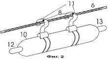
Figure 1 shows the functional block diagram of the device, taking into account its development; figure 2 is a General view of the device installed on the wire of the overhead line.
Осуществление изобретения
На фиг.1 показаны:
1 - блок питания,
2 - блок управления,
3 - блок получения и преобразования сигналов состояния провода ВЛ,
4 - блок предварительной обработки полученной информации, накопления и хранения данных,
5 - блок связи и передачи данных,
6 - провод ВЛ.The implementation of the invention
Figure 1 shows:
1 - power supply,
2 - control unit
3 - block receiving and converting signals of the state of the wire of the overhead line,
4 - block pre-processing of the received information, the accumulation and storage of data,
5 - communication and data transmission unit,
6 - OHL wire.
Блок 1 может быть выполнен в виде аккумулятора и снабжен средствами подзарядки от тока в проводе линии и/или от солнечной батареи, которая в этом случае входит в состав устройства (на фиг.1 не показана).
Блок 2 управляет работой блоков 3, 4 и 5 и устройства в целом. Block 2 controls the operation of blocks 3, 4 and 5 and the device as a whole.
В состав блока 3 входят:
7 - датчик параметров тока в проводе 6,
8 - датчик температуры провода 6,
9 - приемник сигналов глобальной системы позиционирования GPS с определителем его положения в трехмерной системе координат (GPS приемник).Block 3 includes:
7 - sensor current parameters in the
8 -
9 - signal receiver global GPS positioning system with a determinant of its position in a three-dimensional coordinate system (GPS receiver).
На фиг.2 показаны:
10 - корпус устройства,
11 - средства крепления корпуса 10 на проводе 6,
12 и 13 - антенны блока 5 и приемника 9,
а также провод 6 и датчик 8, встроенный в средство 11 (датчик 7 на фиг.2 не показан, а датчик 8 состоит из двух частей).Figure 2 shows:
10 - the device body,
11 - means of mounting the
12 and 13 - antenna unit 5 and receiver 9,
as well as a
Блок 4 связан с выходом блока 3 и входом блока 5 и выполняет функции предварительной обработки полученной информации, накопления и хранения данных. Block 4 is connected with the output of block 3 and the input of block 5 and performs the functions of preprocessing the received information, accumulating and storing data.
Блок 5 обеспечивает связь и передачу данных на пункт сбора измерительной информации. Block 5 provides communication and data transfer to the point of collection of measurement information.
Блоки 2, 4 и 5 могут быть выполнены на базе микропроцессорной техники с программным управлением и конструктивно объединены с блоком 3 в единый измерительно-передающий модуль 14. Blocks 2, 4 and 5 can be made on the basis of microprocessor technology with program control and are structurally combined with block 3 into a single measuring and transmitting module 14.
Средство 15 сопряжения с каналом сотовой телефонии общего пользования, которым снабжен модуль 14, показано на фиг.1 в составе блока 5. Блок 5 может быть снабжен также средствами приема сигналов запроса информации, установочных цифровых данных и защиты от несанкционированного доступа, которые на фиг.1 не показаны. The means 15 for interfacing with the public cellular telephony channel, which the module 14 is equipped with, are shown in FIG. 1 as part of unit 5. Unit 5 can also be equipped with means for receiving information request signals, installation digital data and protection against unauthorized access, which are shown in FIG. 1 are not shown.
Датчик 7 функционирует как трансформатор тока и конструктивно может быть выполнен, например, по типу токовых клещей. The sensor 7 functions as a current transformer and can be structurally made, for example, by the type of current clamp.
Датчик 8 может быть выполнен на основе одной или двух термопар, встроенных (см. фиг.2) в средства 11 крепления корпуса 10 на проводе 6. The sensor 8 can be made on the basis of one or two thermocouples, built-in (see figure 2) in the means 11 for mounting the
Приемник 9, которым снабжен модуль 14, показан на фиг.1 в составе блока 3. Приемник 9 может быть выполнен на базе серийно выпускаемой микросхемы GPS приемника. The receiver 9, which is equipped with the module 14, is shown in figure 1 as part of block 3. The receiver 9 can be made on the basis of a commercially available microcircuit GPS receiver.
Антенны 12 и 13 подсоединены к блоку 5 и приемнику 9 соответственно и обеспечивают их работу.
Устройство устанавливается непосредственно на проводе ВЛ в одном из пролетов линии - предпочтительно в середине пролета или в точке максимального провеса провода - и работает следующим образом. The device is installed directly on the OHL wire in one of the spans of the line — preferably in the middle of the span or at the point of maximum wire sag — and works as follows.
С помощью датчика 8 блок 3 получает аналоговый электрический сигнал, соответствующий температуре провода 6, преобразует его в цифровые данные и передает их в блок 4, где они хранятся, накапливаются и предварительно обрабатываются. Using sensor 8, block 3 receives an analog electrical signal corresponding to the temperature of
С помощью датчика 7 блок 3 получает аналоговый электрический сигнал, соответствующий току в линии (и несущий информацию о величине тока, частоте, фазе и т.п.), преобразует его в цифровые данные и передает их в блок 4, где они хранятся, накапливаются и предварительно обрабатываются. Using sensor 7, block 3 receives an analog electrical signal corresponding to the current in the line (and carries information about the magnitude of the current, frequency, phase, etc.), converts it into digital data and transfers it to block 4, where it is stored, accumulated and pre-processed.
С помощью приемника 9 блок 3 получает сигналы со спутников глобальной системы позиционирования GPS [7]. Приемник 9 снабжен анализатором сигналов системы GPS, который по их относительным задержкам определяет (приблизительно один раз в микросекунду) положение приемника в трехмерной системе координат. Данные о координатах приемника 9 (и, следовательно, провода 6) из блока 3 поступают в блок 4, где они так же, как и данные о других параметрах, хранятся, накапливаются и предварительно обрабатываются. При этом обеспечивается определенное повышение разрешающей способности приемника, позволяющее измерять относительно небольшие перемещения провода ВЛ с помощью системы GPS, первоначально предназначенной для определения местоположения мобильных объектов. Такой эффект связан с тем, что до возникновения интенсивных колебаний провода приемник сигналов GPS длительное время принимает их, находясь практически в стационарном состоянии. Using the receiver 9, block 3 receives signals from the satellites of the global GPS positioning system [7]. The receiver 9 is equipped with a GPS signal analyzer, which, based on their relative delays, determines (approximately once every microsecond) the position of the receiver in a three-dimensional coordinate system. Data on the coordinates of receiver 9 (and, therefore, wires 6) from block 3 are sent to block 4, where they, like the data on other parameters, are stored, accumulated, and pre-processed. This provides a certain increase in the resolution of the receiver, allowing you to measure the relatively small movements of the overhead wire using a GPS system, originally designed to determine the location of mobile objects. This effect is due to the fact that before the occurrence of intense wire vibrations, the GPS signal receiver receives them for a long time, being almost in a stationary state.
Из блока 4 данные поступают в блок 5, который обеспечивает передачу на пункт сбора информации о состоянии (температуре, токе и пространственном положении) провода. From block 4, the data enters block 5, which ensures the transfer to the collection point of information about the state (temperature, current and spatial position) of the wire.
В тех случаях реализации изобретения, когда модуль 14 снабжен средством 15 (модемом), передача данных осуществляется по каналам сотовой телефонии, предоставляемым в общее пользование. Передача данных может осуществляться периодически с интервалом, например, 15 минут либо по запросу из пункта сбора и обработки информации. В последнем случае блок 5 должен быть снабжен средствами приема сигналов запроса информации и может быть связан с блоком 2 цепью 16, инициирующей работу устройства. In those cases where the invention is implemented when the module 14 is equipped with a means 15 (modem), data is transmitted via cellular telephony channels provided for general use. Data transfer can be carried out periodically at intervals of, for example, 15 minutes, or upon request from a collection and processing center. In the latter case, block 5 should be equipped with means for receiving information request signals and may be connected to block 2 with a circuit 16 initiating the operation of the device.
На пункте сбора и обработки информации прием данных и передача сигналов управления (запросов на передачу и установочных данных) осуществляются либо с помощью специализированного устройства, либо с использованием персонального компьютера, сопряжение которых с каналом связи может осуществляться через обычную телефонную линию с помощью стандартного модема. At the point of collection and processing of information, data reception and transmission of control signals (transmission requests and installation data) are carried out either using a specialized device or using a personal computer, which can be connected to a communication channel through a regular telephone line using a standard modem.
Предлагаемое устройство использует известные средства общего пользования (сигналы системы GPS и телефонные каналы сотовой связи) для решения специфической задачи контроля параметров состояния провода высоковольтной линии электропередачи. The proposed device uses well-known public utilities (GPS system signals and cellular telephone channels) to solve the specific task of monitoring the state parameters of a high-voltage power line wire.
При этом сотовая связь используется не по ее прямому назначению (телефонизация мобильных абонентов), а для обеспечения технологической телефонной связи с объектом, находящимся под высоким напряжением. Технический результат от применения сотовой связи в изобретении: исключается необходимость создавать и эксплуатировать как средства высоковольтной развязки, так и специализированную технологическую систему связи. При этом повышается надежность автономной работы устройства, т.к. функционирование телефонной сети связи общего пользования (включая сотовую телефонию), как правило, сохраняется при отказах или перерывах в работе отдельных линий, высоковольтных подстанций, электростанций и даже энергосистем. At the same time, cellular communication is used not for its intended purpose (telephony of mobile subscribers), but to provide technological telephone communication with an object under high voltage. The technical result from the use of cellular communication in the invention: eliminates the need to create and operate as a means of high-voltage isolation, and a specialized technological communication system. This increases the reliability of the autonomous operation of the device, because the functioning of the public switched telephone network (including cellular telephony), as a rule, is maintained during failures or interruptions in the operation of individual lines, high-voltage substations, power plants and even power systems.
Важно отметить, что известное, например из [8], применение мобильной телефонной связи в системе удаленного контроля работы электробытовых приборов не предусматривает передачу данных непосредственно от элементов (датчиков), установленных на токоведущих (и тем более на высоковольтных) частях оборудования, и, следовательно, не сопровождается получением указанного выше технического результата. В [8] решается другая задача и достигается другой технический результат (возможность использования готового и уже имеющегося у пользователя средства - мобильного телефона в качестве удаленного терминала системы), основанный на таком свойстве мобильных телефонов, как наличие дисплея, подходящего для отображения управляющих инструкций и результатов контроля электробытовых приборов. It is important to note that the well-known, for example, from [8], the use of mobile telephony in the remote control system for the operation of household appliances does not provide for the transfer of data directly from elements (sensors) installed on current-carrying (and even more so on high-voltage) parts of equipment, and therefore is not accompanied by the receipt of the above technical result. In [8], another problem is solved and another technical result is achieved (the ability to use a ready-made and already available means of the user - a mobile phone as a remote terminal of the system), based on such a property of mobile phones as the presence of a display suitable for displaying control instructions and results control of household appliances.
Изобретательский уровень данного предложения также подтверждается, например тем, что в источнике [9], описывающем систему контроля параметров электроэнергетических объектов в труднодоступных местах (на высоковольтных и вращающихся частях электрооборудования), не рассматривается использование для этой цели телефонных каналов сотовой связи. The inventive step of this proposal is also confirmed, for example, by the fact that the source [9], which describes the control system for parameters of electric power facilities in hard-to-reach places (on high-voltage and rotating parts of electrical equipment), does not consider the use of cellular telephone channels for this purpose.
Промышленная применимость
Применимость изобретения предполагает выполнение по меньшей мере одного из двух требований к месту размещения устройства на ВЛ:
- оно должно находиться в зоне покрытия хотя бы одной системы мобильной телефонной связи;
- оно должно быть доступно для одновременного приема сигналов по меньшей мере 3-х спутников группировки GPS, общее число которых составляет 21 орбитальный объект.Industrial applicability
The applicability of the invention involves the fulfillment of at least one of two requirements for the location of the device on the overhead line:
- it should be in the coverage area of at least one mobile telephone system;
- it should be available for simultaneous reception of signals from at least 3 GPS constellation satellites, the total number of which is 21 orbital objects.
В настоящее время первое требование выполняется главным образом в развитых регионах с высокой плотностью населения, а второе (благодаря большому общему числу орбитальных объектов группировки GPS, равномерно размещенных на орбите вокруг Земли) - практически в любой точке земной поверхности. Currently, the first requirement is fulfilled mainly in developed regions with a high population density, and the second (due to the large total number of orbital objects of the GPS constellation evenly placed in orbit around the Earth) - almost anywhere on the earth's surface.
Выполнение первого требования дает возможность применить изобретение в первом варианте его реализации, второго - во втором варианте. В обоих случаях обеспечивается технический результат изобретения - повышение надежности автономного функционирования устройства. Fulfillment of the first requirement makes it possible to apply the invention in the first embodiment, and the second in the second embodiment. In both cases, the technical result of the invention is provided — improving the reliability of the autonomous functioning of the device.
С другой стороны выбор варианта реализации изобретения может определяться экономическими соображениями и приоритетной задачей мониторинга состояния проводов ВЛ, зависящей, например, от наличия гололедоопасных участков, силы и направления господствующих ветров на трассе ВЛ, нагруженности линии. On the other hand, the choice of an embodiment of the invention can be determined by economic considerations and the priority task of monitoring the condition of overhead lines, depending, for example, on the presence of ice-hazardous areas, the strength and direction of the prevailing winds on the overhead line, and line loading.
Таким образом, в зависимости от конкретных условий прохождения ВЛ предлагаемое устройство может быть реализовано в двух основных вариантах, каждый из которых предусматривает возможность соответствующего развития с дальнейшим повышением надежности и автономности функционирования, если в месте размещения устройства выполняются оба вышеуказанных требования. Thus, depending on the specific conditions for the passage of overhead lines, the proposed device can be implemented in two main versions, each of which provides for the possibility of corresponding development with a further increase in the reliability and autonomy of functioning if both of the above requirements are met at the location of the device.
Источники информации
1. Мобильный автономный терморегистратор РТВ-1, WWW.carat-ndt.ru/rtv2. htm
2. Laser range finder LEM 300-GEO, www.jenoptik-los.de/lasersensor/range finder/lem300 geo.html.Sources of information
1. Mobile stand-alone temperature recorder RTV-1, WWW.carat-ndt.ru/rtv2. htm
2. Laser range finder LEM 300-GEO, www.jenoptik-los.de/lasersensor/range finder / lem300 geo.html.
3. M. Corti, S.Marazzini, F.Tavano. Misura a distanza delle vibrazioni dei conduttori delle linee elettriche aeree mediante 1'impiego di laser, 85a Riunione Annuale dell'AEI, ottobre 1984. 3. M. Corti, S. Marazzini, F. Tavano. Misura a distanza delle vibrazioni dei conduttori delle linee elettriche aeree mediante 1'impiego di laser, 85a Riunione Annuale dell'AEI, ottobre 1984.
4. Т. Seppa et all. Use of on-line tension monitoring for real-time thermal rating, ice loads, and other environmental effects, CIGRE Session 1998, report 22-102. 4. T. Seppa et all. Use of on-line tension monitoring for real-time thermal rating, ice loads, and other environmental effects, CIGRE Session 1998, report 22-102.
5. Патент РФ 2143165, МПК H 02 J 13/00, G 01 R 15/06. 1999. Устройство для контроля электроэнергетических систем. 5. RF patent 2143165, IPC H 02
6. Микуцкий Г. В. Устройства обработки и присоединения высокочастотных каналов. - M.: Энергия, 1974, с.106-158. 6. Mikutsky G. V. Devices for processing and connecting high-frequency channels. - M .: Energy, 1974, pp. 106-158.
7. Understanding GPS: principles and applications. Edition Elliot D. Kaplan, Arteeh Hons. Boston, London, 1996. 7. Understanding GPS: principles and applications. Edition Elliot D. Kaplan, Arteeh Hons. Boston, London, 1996.
8. Заявка РСТ WO 01/28068, H 02 J 13/00, 2001. System for monitoring and controlling f set of household appliances. 8. PCT Application WO 01/28068, H 02
9. Заявка РСТ WO 01/17092, МПК H 02 J 13/00, 2001. Electric power supervision. 9. PCT Application WO 01/17092, IPC H 02
Claims (20)
Translated fromRussianPriority Applications (8)
| Application Number | Priority Date | Filing Date | Title |
|---|---|---|---|
| RU2002129160/09ARU2222858C1 (en) | 2002-10-31 | 2002-10-31 | Device for remote monitoring of overhead power transmission line conductors for condition (alternatives) |
| AU2003277772AAU2003277772A1 (en) | 2002-10-31 | 2003-10-30 | Device for telemonitoring the state of aerial power lines (variants) |
| AT03809903TATE393376T1 (en) | 2002-10-31 | 2003-10-30 | DEVICE FOR REMOTE MONITORING THE CONDITION OF OVERLAND LINES |
| PCT/RU2003/000460WO2004040239A1 (en) | 2002-10-31 | 2003-10-30 | Device for telemonitoring the state of aerial power lines (variants) |
| DE50309714TDE50309714D1 (en) | 2002-10-31 | 2003-10-30 | DEVICE FOR REMOTELY MONITORING THE CONDITION OF OVERLAND LINEARS |
| US10/533,285US7430932B2 (en) | 2002-10-31 | 2003-10-30 | Device for telemonitoring the state of aerial power lines(variants) |
| BR0315929-9ABR0315929A (en) | 2002-10-31 | 2003-10-30 | Transmission overhead line conductor status controller |
| EP03809903AEP1574822B1 (en) | 2002-10-31 | 2003-10-30 | Device for telemonitoring the state of aerial power lines |
Applications Claiming Priority (1)
| Application Number | Priority Date | Filing Date | Title |
|---|---|---|---|
| RU2002129160/09ARU2222858C1 (en) | 2002-10-31 | 2002-10-31 | Device for remote monitoring of overhead power transmission line conductors for condition (alternatives) |
Publications (2)
| Publication Number | Publication Date |
|---|---|
| RU2222858C1true RU2222858C1 (en) | 2004-01-27 |
| RU2002129160A RU2002129160A (en) | 2004-05-20 |
Family
ID=32091793
Family Applications (1)
| Application Number | Title | Priority Date | Filing Date |
|---|---|---|---|
| RU2002129160/09ARU2222858C1 (en) | 2002-10-31 | 2002-10-31 | Device for remote monitoring of overhead power transmission line conductors for condition (alternatives) |
Country Status (8)
| Country | Link |
|---|---|
| US (1) | US7430932B2 (en) |
| EP (1) | EP1574822B1 (en) |
| AT (1) | ATE393376T1 (en) |
| AU (1) | AU2003277772A1 (en) |
| BR (1) | BR0315929A (en) |
| DE (1) | DE50309714D1 (en) |
| RU (1) | RU2222858C1 (en) |
| WO (1) | WO2004040239A1 (en) |
Cited By (13)
| Publication number | Priority date | Publication date | Assignee | Title |
|---|---|---|---|---|
| RU2372624C1 (en)* | 2008-03-12 | 2009-11-10 | Рустэм Газизович Хузяшев | Method for detection of single-phase earth fault location in ramified overhead power transmission line, method for detection of phase-to-phase short circuit in ramified overhead power transmission line and device for current and voltage monitoring for their realisation |
| RU2379699C2 (en)* | 2006-12-25 | 2010-01-20 | Учреждение образования Белорусский государственный университет информатики и радиоэлектроники | Method for remote control of metrological characteristics of radio-measurement devices based on example of metre for complex parametres of shf-devices |
| WO2011119065A2 (en) | 2010-03-24 | 2011-09-29 | Vladimir Aleksandrovitch Shkaptsov | Remote monitoring device for disposal conductor condition of the overhead transmission line |
| RU2494410C2 (en)* | 2008-06-12 | 2013-09-27 | Абб Текнолоджи Аг | Testing system for ac voltage testing of electric high-voltage components |
| RU2521778C1 (en)* | 2013-01-31 | 2014-07-10 | Константин Юрьевич Соловьев | Device for remote control of wire, lightning protection cable or cable of overhead transmission line |
| RU2536429C1 (en)* | 2013-10-24 | 2014-12-20 | Федеральное государственное унитарное предприятие федеральный научно-производственный центр "Производственное объединение "Старт" им. М.В. Проценко" (ФГУП ФНПЦ "ПО "Старт" им. М.В. Проценко") | System of security protection of overhead power transmission lines |
| RU2545343C1 (en)* | 2012-01-31 | 2015-03-27 | Кхватек Ко., Лтд. | Device to control overhead transmission line and to distribute electric energy with selective switching of communication circuit of directional antennas with low losses |
| RU2562910C2 (en)* | 2009-09-09 | 2015-09-10 | Текнологиан Туткимускескус Втт Ой | Device, system and method for control of wire sag on power transmission line |
| RU2586404C1 (en)* | 2015-04-16 | 2016-06-10 | Федеральное государственное бюджетное образовательное учреждение высшего профессионального образования "Омский государственный университет путей сообщения" | Apparatus for monitoring state of wires |
| RU168020U1 (en)* | 2016-05-11 | 2017-01-17 | Общество с ограниченной ответственностью "МИГ", ООО "МИГ" | Power Line Phase Temperature Measuring Device |
| WO2019160434A1 (en)* | 2018-02-16 | 2019-08-22 | Научно-Технический Центр "Радиотехнических, Устройств И Систем" С Ограниченной Ответственностью | Automatic monitoring of the condition of an overhead transmission conductor |
| RU2771882C1 (en)* | 2018-02-16 | 2022-05-13 | Научно-Технический Центр "Радиотехнических Устройств И Систем" С Ограниченной Ответственностью | Method and system for automatic control of the condition of a wire of overhead power lines |
| WO2023200371A1 (en)* | 2022-04-15 | 2023-10-19 | Общество с ограниченной ответственностью "Система" | Device for monitoring the state of an electric power transmission line |
Families Citing this family (201)
| Publication number | Priority date | Publication date | Assignee | Title |
|---|---|---|---|---|
| US7248158B2 (en)* | 2000-04-14 | 2007-07-24 | Current Technologies, Llc | Automated meter reading power line communication system and method |
| US6998962B2 (en)* | 2000-04-14 | 2006-02-14 | Current Technologies, Llc | Power line communication apparatus and method of using the same |
| US7626497B2 (en) | 2005-05-25 | 2009-12-01 | Current Technologies, Llc | Power line communication vegetation management system and method |
| ES2603839T3 (en)* | 2005-09-16 | 2017-03-01 | Ampacimon S.A. | Device, system and method for real-time monitoring of overhead power lines |
| US7468657B2 (en)* | 2006-01-30 | 2008-12-23 | Current Technologies, Llc | System and method for detecting noise source in a power line communications system |
| US8093745B2 (en)* | 2006-07-07 | 2012-01-10 | Ambient Corporation | Sensing current flowing through a power line |
| US7808774B2 (en)* | 2006-08-30 | 2010-10-05 | Boon Hou Tay | Coupling point temperature and current measuring system |
| US7795877B2 (en)* | 2006-11-02 | 2010-09-14 | Current Technologies, Llc | Power line communication and power distribution parameter measurement system and method |
| DE102007019025A1 (en)* | 2007-04-17 | 2008-09-11 | Siemens Ag | Communication unit for indicating operational malfunctions in substations, is connected at interface provided in substation |
| US7714592B2 (en)* | 2007-11-07 | 2010-05-11 | Current Technologies, Llc | System and method for determining the impedance of a medium voltage power line |
| US20090289637A1 (en)* | 2007-11-07 | 2009-11-26 | Radtke William O | System and Method for Determining the Impedance of a Medium Voltage Power Line |
| US8077049B2 (en)* | 2008-01-20 | 2011-12-13 | Current Technologies, Llc | Method and apparatus for communicating power distribution event and location |
| US8566046B2 (en)* | 2008-01-21 | 2013-10-22 | Current Technologies, Llc | System, device and method for determining power line equipment degradation |
| US8665102B2 (en)* | 2008-07-18 | 2014-03-04 | Schweitzer Engineering Laboratories Inc | Transceiver interface for power system monitoring |
| DE102008046430A1 (en)* | 2008-09-04 | 2010-03-11 | Lapp Engineering & Co. | System for collecting data of an element of a pipeline system and method for acquiring the data of the element of the pipeline system |
| MX2011004874A (en)* | 2008-11-06 | 2011-11-01 | Southwire Co | Real-time power line rating. |
| US8002592B2 (en) | 2008-12-17 | 2011-08-23 | Hubbell Incorporated | Data collecting connection |
| AT508078B1 (en) | 2009-04-08 | 2013-06-15 | Microtronics Engineering GmbH | LADDER ROPE PROBE |
| DE102009048691A1 (en)* | 2009-10-08 | 2011-04-21 | Adensis Gmbh | DC measuring station for finding faulty PV modules in a PV system |
| US20110137483A1 (en)* | 2009-12-03 | 2011-06-09 | Alastar Jenkins | Method of real time remote control of transmission capacity of aerial power lines |
| US10205307B2 (en) | 2010-03-23 | 2019-02-12 | Southwire Company, Llc | Power line maintenance monitoring |
| US9697724B2 (en) | 2010-09-22 | 2017-07-04 | Hubbell Incorporated | Transmission line measuring device and method for connectivity and monitoring |
| US10228001B2 (en) | 2010-09-22 | 2019-03-12 | Hubbell Incorporated | Transmission line measuring device and method for connectivity |
| CN102155935B (en)* | 2011-03-08 | 2012-09-05 | 四川电力科学研究院 | Detection method of icing reversing angle detection device for transmission line divided leads |
| CN102227090B (en)* | 2011-06-27 | 2013-08-21 | 山西省电力公司临汾供电分公司 | Intelligent FA (feeder automation) system of 10kV-carrier communication |
| US9214827B2 (en)* | 2012-02-22 | 2015-12-15 | Electric Power Research Institute, Inc. | Apparatus and method for harvesting power from an overhead transmission conductor |
| CA2880124C (en)* | 2012-07-27 | 2018-12-18 | University Of Kwazulu-Natal | An apparatus for use on a cable; and a system for and method of inspecting a cable |
| HK1210325A1 (en)* | 2012-09-06 | 2016-04-15 | Mastinc. | System and method to monitor powerlines |
| US20140136140A1 (en)* | 2012-11-13 | 2014-05-15 | Elwha Llc | Systems and methods for detecting overhead line motion |
| US9113347B2 (en) | 2012-12-05 | 2015-08-18 | At&T Intellectual Property I, Lp | Backhaul link for distributed antenna system |
| US10009065B2 (en) | 2012-12-05 | 2018-06-26 | At&T Intellectual Property I, L.P. | Backhaul link for distributed antenna system |
| US20140163884A1 (en) | 2012-12-10 | 2014-06-12 | Universite De Liege | Method and system for the determination of wind speeds and incident radiation parameters of overhead power lines |
| US9198500B2 (en) | 2012-12-21 | 2015-12-01 | Murray W. Davis | Portable self powered line mountable electric power line and environment parameter monitoring transmitting and receiving system |
| US9557365B2 (en) | 2013-03-14 | 2017-01-31 | Hubbell Incorporated | Apparatuses, systems and methods for detecting corona |
| US9525524B2 (en) | 2013-05-31 | 2016-12-20 | At&T Intellectual Property I, L.P. | Remote distributed antenna system |
| US9999038B2 (en) | 2013-05-31 | 2018-06-12 | At&T Intellectual Property I, L.P. | Remote distributed antenna system |
| US20150035681A1 (en)* | 2013-08-01 | 2015-02-05 | Schweitzer Engineering Laboratories, Inc. | Point-to-Multipoint Polling in a Monitoring System for an Electric Power Distribution System |
| US8897697B1 (en) | 2013-11-06 | 2014-11-25 | At&T Intellectual Property I, Lp | Millimeter-wave surface-wave communications |
| US9209902B2 (en) | 2013-12-10 | 2015-12-08 | At&T Intellectual Property I, L.P. | Quasi-optical coupler |
| US9692101B2 (en) | 2014-08-26 | 2017-06-27 | At&T Intellectual Property I, L.P. | Guided wave couplers for coupling electromagnetic waves between a waveguide surface and a surface of a wire |
| US9768833B2 (en) | 2014-09-15 | 2017-09-19 | At&T Intellectual Property I, L.P. | Method and apparatus for sensing a condition in a transmission medium of electromagnetic waves |
| US10063280B2 (en) | 2014-09-17 | 2018-08-28 | At&T Intellectual Property I, L.P. | Monitoring and mitigating conditions in a communication network |
| US9628854B2 (en) | 2014-09-29 | 2017-04-18 | At&T Intellectual Property I, L.P. | Method and apparatus for distributing content in a communication network |
| US9615269B2 (en) | 2014-10-02 | 2017-04-04 | At&T Intellectual Property I, L.P. | Method and apparatus that provides fault tolerance in a communication network |
| US9685992B2 (en) | 2014-10-03 | 2017-06-20 | At&T Intellectual Property I, L.P. | Circuit panel network and methods thereof |
| US9503189B2 (en) | 2014-10-10 | 2016-11-22 | At&T Intellectual Property I, L.P. | Method and apparatus for arranging communication sessions in a communication system |
| US9973299B2 (en) | 2014-10-14 | 2018-05-15 | At&T Intellectual Property I, L.P. | Method and apparatus for adjusting a mode of communication in a communication network |
| US9762289B2 (en) | 2014-10-14 | 2017-09-12 | At&T Intellectual Property I, L.P. | Method and apparatus for transmitting or receiving signals in a transportation system |
| US9769020B2 (en) | 2014-10-21 | 2017-09-19 | At&T Intellectual Property I, L.P. | Method and apparatus for responding to events affecting communications in a communication network |
| US9312919B1 (en) | 2014-10-21 | 2016-04-12 | At&T Intellectual Property I, Lp | Transmission device with impairment compensation and methods for use therewith |
| US9627768B2 (en) | 2014-10-21 | 2017-04-18 | At&T Intellectual Property I, L.P. | Guided-wave transmission device with non-fundamental mode propagation and methods for use therewith |
| US9780834B2 (en) | 2014-10-21 | 2017-10-03 | At&T Intellectual Property I, L.P. | Method and apparatus for transmitting electromagnetic waves |
| US9564947B2 (en) | 2014-10-21 | 2017-02-07 | At&T Intellectual Property I, L.P. | Guided-wave transmission device with diversity and methods for use therewith |
| US9653770B2 (en) | 2014-10-21 | 2017-05-16 | At&T Intellectual Property I, L.P. | Guided wave coupler, coupling module and methods for use therewith |
| US9520945B2 (en) | 2014-10-21 | 2016-12-13 | At&T Intellectual Property I, L.P. | Apparatus for providing communication services and methods thereof |
| US9577306B2 (en) | 2014-10-21 | 2017-02-21 | At&T Intellectual Property I, L.P. | Guided-wave transmission device and methods for use therewith |
| US9654173B2 (en) | 2014-11-20 | 2017-05-16 | At&T Intellectual Property I, L.P. | Apparatus for powering a communication device and methods thereof |
| US9544006B2 (en) | 2014-11-20 | 2017-01-10 | At&T Intellectual Property I, L.P. | Transmission device with mode division multiplexing and methods for use therewith |
| US9742462B2 (en) | 2014-12-04 | 2017-08-22 | At&T Intellectual Property I, L.P. | Transmission medium and communication interfaces and methods for use therewith |
| US9461706B1 (en) | 2015-07-31 | 2016-10-04 | At&T Intellectual Property I, Lp | Method and apparatus for exchanging communication signals |
| US9680670B2 (en) | 2014-11-20 | 2017-06-13 | At&T Intellectual Property I, L.P. | Transmission device with channel equalization and control and methods for use therewith |
| US10340573B2 (en) | 2016-10-26 | 2019-07-02 | At&T Intellectual Property I, L.P. | Launcher with cylindrical coupling device and methods for use therewith |
| US9954287B2 (en) | 2014-11-20 | 2018-04-24 | At&T Intellectual Property I, L.P. | Apparatus for converting wireless signals and electromagnetic waves and methods thereof |
| US10009067B2 (en) | 2014-12-04 | 2018-06-26 | At&T Intellectual Property I, L.P. | Method and apparatus for configuring a communication interface |
| US9997819B2 (en) | 2015-06-09 | 2018-06-12 | At&T Intellectual Property I, L.P. | Transmission medium and method for facilitating propagation of electromagnetic waves via a core |
| US9800327B2 (en) | 2014-11-20 | 2017-10-24 | At&T Intellectual Property I, L.P. | Apparatus for controlling operations of a communication device and methods thereof |
| US10243784B2 (en) | 2014-11-20 | 2019-03-26 | At&T Intellectual Property I, L.P. | System for generating topology information and methods thereof |
| US10144036B2 (en) | 2015-01-30 | 2018-12-04 | At&T Intellectual Property I, L.P. | Method and apparatus for mitigating interference affecting a propagation of electromagnetic waves guided by a transmission medium |
| US9876570B2 (en) | 2015-02-20 | 2018-01-23 | At&T Intellectual Property I, Lp | Guided-wave transmission device with non-fundamental mode propagation and methods for use therewith |
| US9749013B2 (en) | 2015-03-17 | 2017-08-29 | At&T Intellectual Property I, L.P. | Method and apparatus for reducing attenuation of electromagnetic waves guided by a transmission medium |
| CN104749510A (en)* | 2015-04-22 | 2015-07-01 | 长安大学 | Pantograph arc online-monitoring and discharge positioning system |
| US10224981B2 (en) | 2015-04-24 | 2019-03-05 | At&T Intellectual Property I, Lp | Passive electrical coupling device and methods for use therewith |
| US9705561B2 (en) | 2015-04-24 | 2017-07-11 | At&T Intellectual Property I, L.P. | Directional coupling device and methods for use therewith |
| US9793954B2 (en) | 2015-04-28 | 2017-10-17 | At&T Intellectual Property I, L.P. | Magnetic coupling device and methods for use therewith |
| US9948354B2 (en) | 2015-04-28 | 2018-04-17 | At&T Intellectual Property I, L.P. | Magnetic coupling device with reflective plate and methods for use therewith |
| US9490869B1 (en) | 2015-05-14 | 2016-11-08 | At&T Intellectual Property I, L.P. | Transmission medium having multiple cores and methods for use therewith |
| US9871282B2 (en) | 2015-05-14 | 2018-01-16 | At&T Intellectual Property I, L.P. | At least one transmission medium having a dielectric surface that is covered at least in part by a second dielectric |
| US9748626B2 (en) | 2015-05-14 | 2017-08-29 | At&T Intellectual Property I, L.P. | Plurality of cables having different cross-sectional shapes which are bundled together to form a transmission medium |
| US10679767B2 (en) | 2015-05-15 | 2020-06-09 | At&T Intellectual Property I, L.P. | Transmission medium having a conductive material and methods for use therewith |
| US10650940B2 (en) | 2015-05-15 | 2020-05-12 | At&T Intellectual Property I, L.P. | Transmission medium having a conductive material and methods for use therewith |
| US9917341B2 (en) | 2015-05-27 | 2018-03-13 | At&T Intellectual Property I, L.P. | Apparatus and method for launching electromagnetic waves and for modifying radial dimensions of the propagating electromagnetic waves |
| US10812174B2 (en) | 2015-06-03 | 2020-10-20 | At&T Intellectual Property I, L.P. | Client node device and methods for use therewith |
| US10103801B2 (en) | 2015-06-03 | 2018-10-16 | At&T Intellectual Property I, L.P. | Host node device and methods for use therewith |
| US9912381B2 (en) | 2015-06-03 | 2018-03-06 | At&T Intellectual Property I, Lp | Network termination and methods for use therewith |
| US10154493B2 (en) | 2015-06-03 | 2018-12-11 | At&T Intellectual Property I, L.P. | Network termination and methods for use therewith |
| US9866309B2 (en) | 2015-06-03 | 2018-01-09 | At&T Intellectual Property I, Lp | Host node device and methods for use therewith |
| US10348391B2 (en) | 2015-06-03 | 2019-07-09 | At&T Intellectual Property I, L.P. | Client node device with frequency conversion and methods for use therewith |
| US9913139B2 (en) | 2015-06-09 | 2018-03-06 | At&T Intellectual Property I, L.P. | Signal fingerprinting for authentication of communicating devices |
| US9608692B2 (en) | 2015-06-11 | 2017-03-28 | At&T Intellectual Property I, L.P. | Repeater and methods for use therewith |
| US10142086B2 (en) | 2015-06-11 | 2018-11-27 | At&T Intellectual Property I, L.P. | Repeater and methods for use therewith |
| US9820146B2 (en) | 2015-06-12 | 2017-11-14 | At&T Intellectual Property I, L.P. | Method and apparatus for authentication and identity management of communicating devices |
| US9667317B2 (en) | 2015-06-15 | 2017-05-30 | At&T Intellectual Property I, L.P. | Method and apparatus for providing security using network traffic adjustments |
| US9640850B2 (en) | 2015-06-25 | 2017-05-02 | At&T Intellectual Property I, L.P. | Methods and apparatus for inducing a non-fundamental wave mode on a transmission medium |
| US9865911B2 (en) | 2015-06-25 | 2018-01-09 | At&T Intellectual Property I, L.P. | Waveguide system for slot radiating first electromagnetic waves that are combined into a non-fundamental wave mode second electromagnetic wave on a transmission medium |
| US9509415B1 (en) | 2015-06-25 | 2016-11-29 | At&T Intellectual Property I, L.P. | Methods and apparatus for inducing a fundamental wave mode on a transmission medium |
| US10033107B2 (en) | 2015-07-14 | 2018-07-24 | At&T Intellectual Property I, L.P. | Method and apparatus for coupling an antenna to a device |
| US10205655B2 (en) | 2015-07-14 | 2019-02-12 | At&T Intellectual Property I, L.P. | Apparatus and methods for communicating utilizing an antenna array and multiple communication paths |
| US10170840B2 (en) | 2015-07-14 | 2019-01-01 | At&T Intellectual Property I, L.P. | Apparatus and methods for sending or receiving electromagnetic signals |
| US9836957B2 (en) | 2015-07-14 | 2017-12-05 | At&T Intellectual Property I, L.P. | Method and apparatus for communicating with premises equipment |
| US9853342B2 (en) | 2015-07-14 | 2017-12-26 | At&T Intellectual Property I, L.P. | Dielectric transmission medium connector and methods for use therewith |
| US10148016B2 (en) | 2015-07-14 | 2018-12-04 | At&T Intellectual Property I, L.P. | Apparatus and methods for communicating utilizing an antenna array |
| US9722318B2 (en) | 2015-07-14 | 2017-08-01 | At&T Intellectual Property I, L.P. | Method and apparatus for coupling an antenna to a device |
| US10044409B2 (en) | 2015-07-14 | 2018-08-07 | At&T Intellectual Property I, L.P. | Transmission medium and methods for use therewith |
| US10320586B2 (en) | 2015-07-14 | 2019-06-11 | At&T Intellectual Property I, L.P. | Apparatus and methods for generating non-interfering electromagnetic waves on an insulated transmission medium |
| US9882257B2 (en) | 2015-07-14 | 2018-01-30 | At&T Intellectual Property I, L.P. | Method and apparatus for launching a wave mode that mitigates interference |
| US10033108B2 (en) | 2015-07-14 | 2018-07-24 | At&T Intellectual Property I, L.P. | Apparatus and methods for generating an electromagnetic wave having a wave mode that mitigates interference |
| US9847566B2 (en) | 2015-07-14 | 2017-12-19 | At&T Intellectual Property I, L.P. | Method and apparatus for adjusting a field of a signal to mitigate interference |
| US9628116B2 (en) | 2015-07-14 | 2017-04-18 | At&T Intellectual Property I, L.P. | Apparatus and methods for transmitting wireless signals |
| US10341142B2 (en) | 2015-07-14 | 2019-07-02 | At&T Intellectual Property I, L.P. | Apparatus and methods for generating non-interfering electromagnetic waves on an uninsulated conductor |
| US9608740B2 (en) | 2015-07-15 | 2017-03-28 | At&T Intellectual Property I, L.P. | Method and apparatus for launching a wave mode that mitigates interference |
| US10090606B2 (en) | 2015-07-15 | 2018-10-02 | At&T Intellectual Property I, L.P. | Antenna system with dielectric array and methods for use therewith |
| US9793951B2 (en) | 2015-07-15 | 2017-10-17 | At&T Intellectual Property I, L.P. | Method and apparatus for launching a wave mode that mitigates interference |
| US10784670B2 (en) | 2015-07-23 | 2020-09-22 | At&T Intellectual Property I, L.P. | Antenna support for aligning an antenna |
| US9871283B2 (en) | 2015-07-23 | 2018-01-16 | At&T Intellectual Property I, Lp | Transmission medium having a dielectric core comprised of plural members connected by a ball and socket configuration |
| US9749053B2 (en) | 2015-07-23 | 2017-08-29 | At&T Intellectual Property I, L.P. | Node device, repeater and methods for use therewith |
| US9912027B2 (en) | 2015-07-23 | 2018-03-06 | At&T Intellectual Property I, L.P. | Method and apparatus for exchanging communication signals |
| US9948333B2 (en) | 2015-07-23 | 2018-04-17 | At&T Intellectual Property I, L.P. | Method and apparatus for wireless communications to mitigate interference |
| US9967173B2 (en) | 2015-07-31 | 2018-05-08 | At&T Intellectual Property I, L.P. | Method and apparatus for authentication and identity management of communicating devices |
| US9735833B2 (en) | 2015-07-31 | 2017-08-15 | At&T Intellectual Property I, L.P. | Method and apparatus for communications management in a neighborhood network |
| US10020587B2 (en) | 2015-07-31 | 2018-07-10 | At&T Intellectual Property I, L.P. | Radial antenna and methods for use therewith |
| US9904535B2 (en) | 2015-09-14 | 2018-02-27 | At&T Intellectual Property I, L.P. | Method and apparatus for distributing software |
| US10136434B2 (en) | 2015-09-16 | 2018-11-20 | At&T Intellectual Property I, L.P. | Method and apparatus for use with a radio distributed antenna system having an ultra-wideband control channel |
| US10051629B2 (en) | 2015-09-16 | 2018-08-14 | At&T Intellectual Property I, L.P. | Method and apparatus for use with a radio distributed antenna system having an in-band reference signal |
| US10079661B2 (en) | 2015-09-16 | 2018-09-18 | At&T Intellectual Property I, L.P. | Method and apparatus for use with a radio distributed antenna system having a clock reference |
| US10009063B2 (en) | 2015-09-16 | 2018-06-26 | At&T Intellectual Property I, L.P. | Method and apparatus for use with a radio distributed antenna system having an out-of-band reference signal |
| US9705571B2 (en) | 2015-09-16 | 2017-07-11 | At&T Intellectual Property I, L.P. | Method and apparatus for use with a radio distributed antenna system |
| US10009901B2 (en) | 2015-09-16 | 2018-06-26 | At&T Intellectual Property I, L.P. | Method, apparatus, and computer-readable storage medium for managing utilization of wireless resources between base stations |
| US9769128B2 (en) | 2015-09-28 | 2017-09-19 | At&T Intellectual Property I, L.P. | Method and apparatus for encryption of communications over a network |
| US9729197B2 (en) | 2015-10-01 | 2017-08-08 | At&T Intellectual Property I, L.P. | Method and apparatus for communicating network management traffic over a network |
| US9876264B2 (en) | 2015-10-02 | 2018-01-23 | At&T Intellectual Property I, Lp | Communication system, guided wave switch and methods for use therewith |
| US10074890B2 (en) | 2015-10-02 | 2018-09-11 | At&T Intellectual Property I, L.P. | Communication device and antenna with integrated light assembly |
| US9882277B2 (en) | 2015-10-02 | 2018-01-30 | At&T Intellectual Property I, Lp | Communication device and antenna assembly with actuated gimbal mount |
| US10665942B2 (en) | 2015-10-16 | 2020-05-26 | At&T Intellectual Property I, L.P. | Method and apparatus for adjusting wireless communications |
| US10355367B2 (en) | 2015-10-16 | 2019-07-16 | At&T Intellectual Property I, L.P. | Antenna structure for exchanging wireless signals |
| US10051483B2 (en) | 2015-10-16 | 2018-08-14 | At&T Intellectual Property I, L.P. | Method and apparatus for directing wireless signals |
| WO2017180668A1 (en)* | 2016-04-11 | 2017-10-19 | Lindsey Manufacturing Co. | Dropped conductor sensor |
| US9912419B1 (en) | 2016-08-24 | 2018-03-06 | At&T Intellectual Property I, L.P. | Method and apparatus for managing a fault in a distributed antenna system |
| US9860075B1 (en) | 2016-08-26 | 2018-01-02 | At&T Intellectual Property I, L.P. | Method and communication node for broadband distribution |
| US10291311B2 (en) | 2016-09-09 | 2019-05-14 | At&T Intellectual Property I, L.P. | Method and apparatus for mitigating a fault in a distributed antenna system |
| US11032819B2 (en) | 2016-09-15 | 2021-06-08 | At&T Intellectual Property I, L.P. | Method and apparatus for use with a radio distributed antenna system having a control channel reference signal |
| US10135147B2 (en) | 2016-10-18 | 2018-11-20 | At&T Intellectual Property I, L.P. | Apparatus and methods for launching guided waves via an antenna |
| US10135146B2 (en) | 2016-10-18 | 2018-11-20 | At&T Intellectual Property I, L.P. | Apparatus and methods for launching guided waves via circuits |
| US10340600B2 (en) | 2016-10-18 | 2019-07-02 | At&T Intellectual Property I, L.P. | Apparatus and methods for launching guided waves via plural waveguide systems |
| US10811767B2 (en) | 2016-10-21 | 2020-10-20 | At&T Intellectual Property I, L.P. | System and dielectric antenna with convex dielectric radome |
| US9991580B2 (en) | 2016-10-21 | 2018-06-05 | At&T Intellectual Property I, L.P. | Launcher and coupling system for guided wave mode cancellation |
| US10374316B2 (en) | 2016-10-21 | 2019-08-06 | At&T Intellectual Property I, L.P. | System and dielectric antenna with non-uniform dielectric |
| US9876605B1 (en) | 2016-10-21 | 2018-01-23 | At&T Intellectual Property I, L.P. | Launcher and coupling system to support desired guided wave mode |
| US10312567B2 (en) | 2016-10-26 | 2019-06-04 | At&T Intellectual Property I, L.P. | Launcher with planar strip antenna and methods for use therewith |
| US10224634B2 (en) | 2016-11-03 | 2019-03-05 | At&T Intellectual Property I, L.P. | Methods and apparatus for adjusting an operational characteristic of an antenna |
| US10225025B2 (en) | 2016-11-03 | 2019-03-05 | At&T Intellectual Property I, L.P. | Method and apparatus for detecting a fault in a communication system |
| US10291334B2 (en) | 2016-11-03 | 2019-05-14 | At&T Intellectual Property I, L.P. | System for detecting a fault in a communication system |
| US10498044B2 (en) | 2016-11-03 | 2019-12-03 | At&T Intellectual Property I, L.P. | Apparatus for configuring a surface of an antenna |
| US10535928B2 (en) | 2016-11-23 | 2020-01-14 | At&T Intellectual Property I, L.P. | Antenna system and methods for use therewith |
| US10090594B2 (en) | 2016-11-23 | 2018-10-02 | At&T Intellectual Property I, L.P. | Antenna system having structural configurations for assembly |
| US10340601B2 (en) | 2016-11-23 | 2019-07-02 | At&T Intellectual Property I, L.P. | Multi-antenna system and methods for use therewith |
| US10340603B2 (en) | 2016-11-23 | 2019-07-02 | At&T Intellectual Property I, L.P. | Antenna system having shielded structural configurations for assembly |
| US10178445B2 (en) | 2016-11-23 | 2019-01-08 | At&T Intellectual Property I, L.P. | Methods, devices, and systems for load balancing between a plurality of waveguides |
| US10361489B2 (en) | 2016-12-01 | 2019-07-23 | At&T Intellectual Property I, L.P. | Dielectric dish antenna system and methods for use therewith |
| US10305190B2 (en) | 2016-12-01 | 2019-05-28 | At&T Intellectual Property I, L.P. | Reflecting dielectric antenna system and methods for use therewith |
| US10439675B2 (en) | 2016-12-06 | 2019-10-08 | At&T Intellectual Property I, L.P. | Method and apparatus for repeating guided wave communication signals |
| US9927517B1 (en) | 2016-12-06 | 2018-03-27 | At&T Intellectual Property I, L.P. | Apparatus and methods for sensing rainfall |
| US10819035B2 (en) | 2016-12-06 | 2020-10-27 | At&T Intellectual Property I, L.P. | Launcher with helical antenna and methods for use therewith |
| US10694379B2 (en) | 2016-12-06 | 2020-06-23 | At&T Intellectual Property I, L.P. | Waveguide system with device-based authentication and methods for use therewith |
| US10020844B2 (en) | 2016-12-06 | 2018-07-10 | T&T Intellectual Property I, L.P. | Method and apparatus for broadcast communication via guided waves |
| US10755542B2 (en) | 2016-12-06 | 2020-08-25 | At&T Intellectual Property I, L.P. | Method and apparatus for surveillance via guided wave communication |
| US10637149B2 (en) | 2016-12-06 | 2020-04-28 | At&T Intellectual Property I, L.P. | Injection molded dielectric antenna and methods for use therewith |
| US10382976B2 (en) | 2016-12-06 | 2019-08-13 | At&T Intellectual Property I, L.P. | Method and apparatus for managing wireless communications based on communication paths and network device positions |
| US10727599B2 (en) | 2016-12-06 | 2020-07-28 | At&T Intellectual Property I, L.P. | Launcher with slot antenna and methods for use therewith |
| US10135145B2 (en) | 2016-12-06 | 2018-11-20 | At&T Intellectual Property I, L.P. | Apparatus and methods for generating an electromagnetic wave along a transmission medium |
| US10326494B2 (en) | 2016-12-06 | 2019-06-18 | At&T Intellectual Property I, L.P. | Apparatus for measurement de-embedding and methods for use therewith |
| US10547348B2 (en) | 2016-12-07 | 2020-01-28 | At&T Intellectual Property I, L.P. | Method and apparatus for switching transmission mediums in a communication system |
| US10389029B2 (en) | 2016-12-07 | 2019-08-20 | At&T Intellectual Property I, L.P. | Multi-feed dielectric antenna system with core selection and methods for use therewith |
| US9893795B1 (en) | 2016-12-07 | 2018-02-13 | At&T Intellectual Property I, Lp | Method and repeater for broadband distribution |
| US10168695B2 (en) | 2016-12-07 | 2019-01-01 | At&T Intellectual Property I, L.P. | Method and apparatus for controlling an unmanned aircraft |
| US10139820B2 (en) | 2016-12-07 | 2018-11-27 | At&T Intellectual Property I, L.P. | Method and apparatus for deploying equipment of a communication system |
| US10446936B2 (en) | 2016-12-07 | 2019-10-15 | At&T Intellectual Property I, L.P. | Multi-feed dielectric antenna system and methods for use therewith |
| US10359749B2 (en) | 2016-12-07 | 2019-07-23 | At&T Intellectual Property I, L.P. | Method and apparatus for utilities management via guided wave communication |
| US10027397B2 (en) | 2016-12-07 | 2018-07-17 | At&T Intellectual Property I, L.P. | Distributed antenna system and methods for use therewith |
| US10243270B2 (en) | 2016-12-07 | 2019-03-26 | At&T Intellectual Property I, L.P. | Beam adaptive multi-feed dielectric antenna system and methods for use therewith |
| US10916969B2 (en) | 2016-12-08 | 2021-02-09 | At&T Intellectual Property I, L.P. | Method and apparatus for providing power using an inductive coupling |
| US10103422B2 (en) | 2016-12-08 | 2018-10-16 | At&T Intellectual Property I, L.P. | Method and apparatus for mounting network devices |
| US10326689B2 (en) | 2016-12-08 | 2019-06-18 | At&T Intellectual Property I, L.P. | Method and system for providing alternative communication paths |
| US10530505B2 (en) | 2016-12-08 | 2020-01-07 | At&T Intellectual Property I, L.P. | Apparatus and methods for launching electromagnetic waves along a transmission medium |
| US10411356B2 (en) | 2016-12-08 | 2019-09-10 | At&T Intellectual Property I, L.P. | Apparatus and methods for selectively targeting communication devices with an antenna array |
| US10601494B2 (en) | 2016-12-08 | 2020-03-24 | At&T Intellectual Property I, L.P. | Dual-band communication device and method for use therewith |
| US10389037B2 (en) | 2016-12-08 | 2019-08-20 | At&T Intellectual Property I, L.P. | Apparatus and methods for selecting sections of an antenna array and use therewith |
| US9998870B1 (en) | 2016-12-08 | 2018-06-12 | At&T Intellectual Property I, L.P. | Method and apparatus for proximity sensing |
| US9911020B1 (en) | 2016-12-08 | 2018-03-06 | At&T Intellectual Property I, L.P. | Method and apparatus for tracking via a radio frequency identification device |
| US10777873B2 (en) | 2016-12-08 | 2020-09-15 | At&T Intellectual Property I, L.P. | Method and apparatus for mounting network devices |
| US10069535B2 (en) | 2016-12-08 | 2018-09-04 | At&T Intellectual Property I, L.P. | Apparatus and methods for launching electromagnetic waves having a certain electric field structure |
| US10938108B2 (en) | 2016-12-08 | 2021-03-02 | At&T Intellectual Property I, L.P. | Frequency selective multi-feed dielectric antenna system and methods for use therewith |
| US10340983B2 (en) | 2016-12-09 | 2019-07-02 | At&T Intellectual Property I, L.P. | Method and apparatus for surveying remote sites via guided wave communications |
| US10264586B2 (en) | 2016-12-09 | 2019-04-16 | At&T Mobility Ii Llc | Cloud-based packet controller and methods for use therewith |
| US9838896B1 (en) | 2016-12-09 | 2017-12-05 | At&T Intellectual Property I, L.P. | Method and apparatus for assessing network coverage |
| US9973940B1 (en) | 2017-02-27 | 2018-05-15 | At&T Intellectual Property I, L.P. | Apparatus and methods for dynamic impedance matching of a guided wave launcher |
| US10298293B2 (en) | 2017-03-13 | 2019-05-21 | At&T Intellectual Property I, L.P. | Apparatus of communication utilizing wireless network devices |
| CN108594080A (en)* | 2018-05-30 | 2018-09-28 | 武汉国鼎科技有限公司 | The full-automatic online navigation positioning system of cable fault |
| IT201800011059A1 (en) | 2018-12-13 | 2020-06-13 | C R M Consulenze Ricerche Mecc S R L | Wind-induced motion or vibration monitoring system in at least one suspended cable, in particular an overhead cable conducting a transmission or distribution power line; relative method and relative sensor |
| CN109412902B (en)* | 2018-12-19 | 2022-04-12 | 国网山西省电力公司 | An intelligent monitoring method, storage device, terminal and system for a power dispatching data network system |
| CN109902351A (en)* | 2019-01-28 | 2019-06-18 | 浙江大学 | A simplified calculation method for dynamic wind deflection of ice-coated conductors |
| US11397198B2 (en) | 2019-08-23 | 2022-07-26 | Schweitzer Engineering Laboratories, Inc. | Wireless current sensor |
Citations (4)
| Publication number | Priority date | Publication date | Assignee | Title |
|---|---|---|---|---|
| US4689752A (en)* | 1983-04-13 | 1987-08-25 | Niagara Mohawk Power Corporation | System and apparatus for monitoring and control of a bulk electric power delivery system |
| RU2132106C1 (en)* | 1997-10-20 | 1999-06-20 | Открытое акционерное общество "Свердловэнерго" | Device for checking electrical equipment |
| RU2143165C1 (en)* | 1998-05-29 | 1999-12-20 | Молочков Виктор Федорович | Device controlling electric power systems |
| WO2001015300A1 (en)* | 1999-08-20 | 2001-03-01 | Wrap S.P.A. | Device, system and method for monitoring a household electric appliance |
Family Cites Families (21)
| Publication number | Priority date | Publication date | Assignee | Title |
|---|---|---|---|---|
| US4420752A (en) | 1978-03-20 | 1983-12-13 | Murray W. Davis | Real-time parameter sensor-transmitter |
| US4709339A (en)* | 1983-04-13 | 1987-11-24 | Fernandes Roosevelt A | Electrical power line parameter measurement apparatus and systems, including compact, line-mounted modules |
| US4794328A (en)* | 1983-04-13 | 1988-12-27 | Niagara Mohawk Power Corporation | Tool for mounting a sensor module on a live power transmission line |
| US4723220A (en)* | 1983-04-13 | 1988-02-02 | Niagara Mohawk Power Corporation | Apparatus for power measuring and calculating Fourier components of power line parameters |
| US4799005A (en)* | 1983-04-13 | 1989-01-17 | Fernandes Roosevelt A | Electrical power line parameter measurement apparatus and systems, including compact, line-mounted modules |
| US4794327A (en)* | 1983-04-13 | 1988-12-27 | Fernandes Roosevelt A | Electrical parameter sensing module for mounting on and removal from an energized high voltage power conductor |
| US4829298A (en)* | 1983-04-13 | 1989-05-09 | Fernandes Roosevelt A | Electrical power line monitoring systems, including harmonic value measurements and relaying communications |
| US4746241A (en)* | 1983-04-13 | 1988-05-24 | Niagara Mohawk Power Corporation | Hinge clamp for securing a sensor module on a power transmission line |
| US4714893A (en)* | 1983-04-13 | 1987-12-22 | Niagara Mohawk Power Corporation | Apparatus for measuring the potential of a transmission line conductor |
| US5029101A (en)* | 1987-09-18 | 1991-07-02 | Fernandes Roosevelt A | High voltage conductor mounted line powered monitoring system |
| US4904996A (en)* | 1988-01-19 | 1990-02-27 | Fernandes Roosevelt A | Line-mounted, movable, power line monitoring system |
| US5181026A (en)* | 1990-01-12 | 1993-01-19 | Granville Group, Inc., The | Power transmission line monitoring system |
| US5565783A (en)* | 1994-09-29 | 1996-10-15 | Pacific Gas And Electric Company | Fault sensor device with radio transceiver |
| US6072396A (en)* | 1994-12-30 | 2000-06-06 | Advanced Business Sciences | Apparatus and method for continuous electronic monitoring and tracking of individuals |
| GB9805556D0 (en)* | 1998-03-17 | 1998-05-13 | Crimewatch Scotland Limited | Alarm systems |
| JPH11281702A (en)* | 1998-03-27 | 1999-10-15 | Ngk Insulators Ltd | Overcurrent detecting device for distribution line |
| JPH11281700A (en)* | 1998-03-27 | 1999-10-15 | Ngk Insulators Ltd | Device for detecting portable distribution-line fault |
| US6421354B1 (en)* | 1999-08-18 | 2002-07-16 | Phoenix Datacomm, Inc. | System and method for retrieval of data from remote sensors using multiple communication channels |
| JP3830699B2 (en)* | 1999-11-11 | 2006-10-04 | 株式会社東芝 | Accident location system |
| JP2002162431A (en)* | 2000-11-22 | 2002-06-07 | Fuji Electric Co Ltd | Fault location system |
| US20030218549A1 (en)* | 2002-04-26 | 2003-11-27 | Oleg Logvinov | Powerline communications system for providing multiple services to isolated power generating plants |
- 2002
- 2002-10-31RURU2002129160/09Apatent/RU2222858C1/ennot_activeIP Right Cessation
- 2003
- 2003-10-30ATAT03809903Tpatent/ATE393376T1/ennot_activeIP Right Cessation
- 2003-10-30AUAU2003277772Apatent/AU2003277772A1/ennot_activeAbandoned
- 2003-10-30WOPCT/RU2003/000460patent/WO2004040239A1/ennot_activeApplication Discontinuation
- 2003-10-30BRBR0315929-9Apatent/BR0315929A/ennot_activeIP Right Cessation
- 2003-10-30DEDE50309714Tpatent/DE50309714D1/ennot_activeExpired - Fee Related
- 2003-10-30USUS10/533,285patent/US7430932B2/ennot_activeExpired - Fee Related
- 2003-10-30EPEP03809903Apatent/EP1574822B1/ennot_activeExpired - Lifetime
Patent Citations (4)
| Publication number | Priority date | Publication date | Assignee | Title |
|---|---|---|---|---|
| US4689752A (en)* | 1983-04-13 | 1987-08-25 | Niagara Mohawk Power Corporation | System and apparatus for monitoring and control of a bulk electric power delivery system |
| RU2132106C1 (en)* | 1997-10-20 | 1999-06-20 | Открытое акционерное общество "Свердловэнерго" | Device for checking electrical equipment |
| RU2143165C1 (en)* | 1998-05-29 | 1999-12-20 | Молочков Виктор Федорович | Device controlling electric power systems |
| WO2001015300A1 (en)* | 1999-08-20 | 2001-03-01 | Wrap S.P.A. | Device, system and method for monitoring a household electric appliance |
Cited By (16)
| Publication number | Priority date | Publication date | Assignee | Title |
|---|---|---|---|---|
| RU2379699C2 (en)* | 2006-12-25 | 2010-01-20 | Учреждение образования Белорусский государственный университет информатики и радиоэлектроники | Method for remote control of metrological characteristics of radio-measurement devices based on example of metre for complex parametres of shf-devices |
| RU2372624C1 (en)* | 2008-03-12 | 2009-11-10 | Рустэм Газизович Хузяшев | Method for detection of single-phase earth fault location in ramified overhead power transmission line, method for detection of phase-to-phase short circuit in ramified overhead power transmission line and device for current and voltage monitoring for their realisation |
| RU2497138C2 (en)* | 2008-06-12 | 2013-10-27 | Абб Текнолоджи Аг | Test system for varying voltage test of high-voltage electric components |
| RU2494410C2 (en)* | 2008-06-12 | 2013-09-27 | Абб Текнолоджи Аг | Testing system for ac voltage testing of electric high-voltage components |
| RU2562910C2 (en)* | 2009-09-09 | 2015-09-10 | Текнологиан Туткимускескус Втт Ой | Device, system and method for control of wire sag on power transmission line |
| WO2011119065A2 (en) | 2010-03-24 | 2011-09-29 | Vladimir Aleksandrovitch Shkaptsov | Remote monitoring device for disposal conductor condition of the overhead transmission line |
| RU2545343C1 (en)* | 2012-01-31 | 2015-03-27 | Кхватек Ко., Лтд. | Device to control overhead transmission line and to distribute electric energy with selective switching of communication circuit of directional antennas with low losses |
| RU2521778C1 (en)* | 2013-01-31 | 2014-07-10 | Константин Юрьевич Соловьев | Device for remote control of wire, lightning protection cable or cable of overhead transmission line |
| RU2536429C1 (en)* | 2013-10-24 | 2014-12-20 | Федеральное государственное унитарное предприятие федеральный научно-производственный центр "Производственное объединение "Старт" им. М.В. Проценко" (ФГУП ФНПЦ "ПО "Старт" им. М.В. Проценко") | System of security protection of overhead power transmission lines |
| RU2586404C1 (en)* | 2015-04-16 | 2016-06-10 | Федеральное государственное бюджетное образовательное учреждение высшего профессионального образования "Омский государственный университет путей сообщения" | Apparatus for monitoring state of wires |
| RU168020U1 (en)* | 2016-05-11 | 2017-01-17 | Общество с ограниченной ответственностью "МИГ", ООО "МИГ" | Power Line Phase Temperature Measuring Device |
| WO2019160434A1 (en)* | 2018-02-16 | 2019-08-22 | Научно-Технический Центр "Радиотехнических, Устройств И Систем" С Ограниченной Ответственностью | Automatic monitoring of the condition of an overhead transmission conductor |
| RU2771882C1 (en)* | 2018-02-16 | 2022-05-13 | Научно-Технический Центр "Радиотехнических Устройств И Систем" С Ограниченной Ответственностью | Method and system for automatic control of the condition of a wire of overhead power lines |
| RU215086U1 (en)* | 2022-04-15 | 2022-11-28 | Общество с ограниченной ответственностью "Система" | Device for monitoring the state of a power line |
| RU2785203C1 (en)* | 2022-04-15 | 2022-12-05 | Общество с ограниченной ответственностью "Система" | Apparatus for monitoring the condition of a power transmission line |
| WO2023200371A1 (en)* | 2022-04-15 | 2023-10-19 | Общество с ограниченной ответственностью "Система" | Device for monitoring the state of an electric power transmission line |
Also Published As
| Publication number | Publication date |
|---|---|
| DE50309714D1 (en) | 2008-06-05 |
| EP1574822A1 (en) | 2005-09-14 |
| EP1574822B1 (en) | 2008-04-23 |
| US7430932B2 (en) | 2008-10-07 |
| WO2004040239A1 (en) | 2004-05-13 |
| EP1574822A4 (en) | 2005-12-14 |
| US20060060007A1 (en) | 2006-03-23 |
| BR0315929A (en) | 2005-09-13 |
| AU2003277772A1 (en) | 2004-05-25 |
| ATE393376T1 (en) | 2008-05-15 |
Similar Documents
| Publication | Publication Date | Title |
|---|---|---|
| RU2222858C1 (en) | Device for remote monitoring of overhead power transmission line conductors for condition (alternatives) | |
| EP2486554B1 (en) | Loads management and outages detection for smart grid | |
| US20110137483A1 (en) | Method of real time remote control of transmission capacity of aerial power lines | |
| CN101076735B (en) | An electrical instrument platform for mounting on and removal from an energized high voltage power conductor | |
| US9689977B2 (en) | System and method to monitor powerlines | |
| RU2002129160A (en) | DEVICE FOR REMOTE CONTROL OF THE CONDITION OF THE ELECTRIC TRANSMISSION AIR LINE WIRE (OPTIONS) | |
| KR100605416B1 (en) | Temperature recorder and temperature record management system of power transmission facility | |
| CN100592567C (en) | Intelligent Telemetry Battery | |
| CN114166274A (en) | Wire sag online monitoring system based on differential Beidou technology | |
| WO2000004392A1 (en) | An electrical supply measurement and management system | |
| JP3906155B2 (en) | Electricity department temperature monitoring device | |
| CN215643091U (en) | Remote instrument data acquisition and transmission system | |
| JP2000341882A (en) | Data collection device in power system | |
| JP5346222B2 (en) | Remote meter reading system | |
| JPH11136823A (en) | Transmission line position measurement method and system | |
| JP7110661B2 (en) | measurement system | |
| WO2023161650A1 (en) | Utility pole monitoring | |
| CN210689704U (en) | Cable monitoring system, intelligent cable clamp and cable system | |
| GB2327566A (en) | Method of Orienting an Antenna | |
| CN208569050U (en) | Electric instrument system | |
| GB2325589A (en) | Electric meter transmitting consumption data via cellular radio | |
| KR102567220B1 (en) | RF temperature sensor for switchboard terminals, and switchboard device equipped with the RF temperature sensor, and monitoring system of a temperature of the switchboard device | |
| RU2820314C1 (en) | System for monitoring corrosion protection parameters of gas distribution networks | |
| RU2786764C1 (en) | Complex for monitoring and controlling electrical loads | |
| RU2799705C1 (en) | Complex for monitoring and controlling electrical loads with control of phase currents and current in the neutral conductor |
Legal Events
| Date | Code | Title | Description |
|---|---|---|---|
| QB4A | Licence on use of patent | Effective date:20051018 | |
| MM4A | The patent is invalid due to non-payment of fees | Effective date:20131101 |