RU2220643C2 - Automatic cleaning apparatus, automatic cleaning system and method for controlling of system (versions) - Google Patents
Automatic cleaning apparatus, automatic cleaning system and method for controlling of system (versions)Download PDFInfo
- Publication number
- RU2220643C2 RU2220643C2RU2001133030/12ARU2001133030ARU2220643C2RU 2220643 C2RU2220643 C2RU 2220643C2RU 2001133030/12 ARU2001133030/12 ARU 2001133030/12ARU 2001133030 ARU2001133030 ARU 2001133030ARU 2220643 C2RU2220643 C2RU 2220643C2
- Authority
- RU
- Russia
- Prior art keywords
- image
- movement
- cleaning
- cleaning device
- map
- Prior art date
Links
- 238000004140cleaningMethods0.000titleclaimsabstractdescription177
- 238000000034methodMethods0.000titleclaimsabstractdescription31
- 230000033001locomotionEffects0.000claimsabstractdescription93
- 238000004891communicationMethods0.000claimsabstractdescription7
- 238000012937correctionMethods0.000claimsdescription7
- 230000005019pattern of movementEffects0.000claimsdescription3
- 230000001131transforming effectEffects0.000claimsdescription3
- 238000006243chemical reactionMethods0.000claimsdescription2
- 238000010191image analysisMethods0.000claims1
- 238000001454recorded imageMethods0.000claims1
- 230000000694effectsEffects0.000abstract1
- 239000000126substanceSubstances0.000abstract1
- 238000012545processingMethods0.000description5
- 238000003860storageMethods0.000description5
- 238000001514detection methodMethods0.000description4
- 238000003672processing methodMethods0.000description4
- 238000002604ultrasonographyMethods0.000description3
- 230000005540biological transmissionEffects0.000description2
- 238000010586diagramMethods0.000description2
- 238000009826distributionMethods0.000description2
- 238000012544monitoring processMethods0.000description2
- 238000012546transferMethods0.000description2
- 238000004458analytical methodMethods0.000description1
- 239000000428dustSubstances0.000description1
- 239000012634fragmentSubstances0.000description1
- 230000006870functionEffects0.000description1
- 229910052602gypsumInorganic materials0.000description1
- 239000010440gypsumSubstances0.000description1
- 238000013507mappingMethods0.000description1
- 238000010926purgeMethods0.000description1
Images


Classifications
- G—PHYSICS
- G05—CONTROLLING; REGULATING
- G05D—SYSTEMS FOR CONTROLLING OR REGULATING NON-ELECTRIC VARIABLES
- G05D1/00—Control of position, course, altitude or attitude of land, water, air or space vehicles, e.g. using automatic pilots
- G05D1/02—Control of position or course in two dimensions
- G05D1/021—Control of position or course in two dimensions specially adapted to land vehicles
- G05D1/0268—Control of position or course in two dimensions specially adapted to land vehicles using internal positioning means
- G05D1/0274—Control of position or course in two dimensions specially adapted to land vehicles using internal positioning means using mapping information stored in a memory device
- A—HUMAN NECESSITIES
- A47—FURNITURE; DOMESTIC ARTICLES OR APPLIANCES; COFFEE MILLS; SPICE MILLS; SUCTION CLEANERS IN GENERAL
- A47L—DOMESTIC WASHING OR CLEANING; SUCTION CLEANERS IN GENERAL
- A47L9/00—Details or accessories of suction cleaners, e.g. mechanical means for controlling the suction or for effecting pulsating action; Storing devices specially adapted to suction cleaners or parts thereof; Carrying-vehicles specially adapted for suction cleaners
- A47L9/009—Carrying-vehicles; Arrangements of trollies or wheels; Means for avoiding mechanical obstacles
- A—HUMAN NECESSITIES
- A47—FURNITURE; DOMESTIC ARTICLES OR APPLIANCES; COFFEE MILLS; SPICE MILLS; SUCTION CLEANERS IN GENERAL
- A47L—DOMESTIC WASHING OR CLEANING; SUCTION CLEANERS IN GENERAL
- A47L9/00—Details or accessories of suction cleaners, e.g. mechanical means for controlling the suction or for effecting pulsating action; Storing devices specially adapted to suction cleaners or parts thereof; Carrying-vehicles specially adapted for suction cleaners
- A47L9/28—Installation of the electric equipment, e.g. adaptation or attachment to the suction cleaner; Controlling suction cleaners by electric means
- A47L9/2805—Parameters or conditions being sensed
- A—HUMAN NECESSITIES
- A47—FURNITURE; DOMESTIC ARTICLES OR APPLIANCES; COFFEE MILLS; SPICE MILLS; SUCTION CLEANERS IN GENERAL
- A47L—DOMESTIC WASHING OR CLEANING; SUCTION CLEANERS IN GENERAL
- A47L9/00—Details or accessories of suction cleaners, e.g. mechanical means for controlling the suction or for effecting pulsating action; Storing devices specially adapted to suction cleaners or parts thereof; Carrying-vehicles specially adapted for suction cleaners
- A47L9/28—Installation of the electric equipment, e.g. adaptation or attachment to the suction cleaner; Controlling suction cleaners by electric means
- A47L9/2836—Installation of the electric equipment, e.g. adaptation or attachment to the suction cleaner; Controlling suction cleaners by electric means characterised by the parts which are controlled
- A47L9/2852—Elements for displacement of the vacuum cleaner or the accessories therefor, e.g. wheels, casters or nozzles
- A—HUMAN NECESSITIES
- A47—FURNITURE; DOMESTIC ARTICLES OR APPLIANCES; COFFEE MILLS; SPICE MILLS; SUCTION CLEANERS IN GENERAL
- A47L—DOMESTIC WASHING OR CLEANING; SUCTION CLEANERS IN GENERAL
- A47L9/00—Details or accessories of suction cleaners, e.g. mechanical means for controlling the suction or for effecting pulsating action; Storing devices specially adapted to suction cleaners or parts thereof; Carrying-vehicles specially adapted for suction cleaners
- A47L9/28—Installation of the electric equipment, e.g. adaptation or attachment to the suction cleaner; Controlling suction cleaners by electric means
- A47L9/2857—User input or output elements for control, e.g. buttons, switches or displays
- A—HUMAN NECESSITIES
- A47—FURNITURE; DOMESTIC ARTICLES OR APPLIANCES; COFFEE MILLS; SPICE MILLS; SUCTION CLEANERS IN GENERAL
- A47L—DOMESTIC WASHING OR CLEANING; SUCTION CLEANERS IN GENERAL
- A47L9/00—Details or accessories of suction cleaners, e.g. mechanical means for controlling the suction or for effecting pulsating action; Storing devices specially adapted to suction cleaners or parts thereof; Carrying-vehicles specially adapted for suction cleaners
- A47L9/28—Installation of the electric equipment, e.g. adaptation or attachment to the suction cleaner; Controlling suction cleaners by electric means
- A47L9/2868—Arrangements for power supply of vacuum cleaners or the accessories thereof
- A47L9/2884—Details of arrangements of batteries or their installation
- A—HUMAN NECESSITIES
- A47—FURNITURE; DOMESTIC ARTICLES OR APPLIANCES; COFFEE MILLS; SPICE MILLS; SUCTION CLEANERS IN GENERAL
- A47L—DOMESTIC WASHING OR CLEANING; SUCTION CLEANERS IN GENERAL
- A47L9/00—Details or accessories of suction cleaners, e.g. mechanical means for controlling the suction or for effecting pulsating action; Storing devices specially adapted to suction cleaners or parts thereof; Carrying-vehicles specially adapted for suction cleaners
- A47L9/28—Installation of the electric equipment, e.g. adaptation or attachment to the suction cleaner; Controlling suction cleaners by electric means
- A47L9/2894—Details related to signal transmission in suction cleaners
- G—PHYSICS
- G05—CONTROLLING; REGULATING
- G05D—SYSTEMS FOR CONTROLLING OR REGULATING NON-ELECTRIC VARIABLES
- G05D1/00—Control of position, course, altitude or attitude of land, water, air or space vehicles, e.g. using automatic pilots
- G05D1/02—Control of position or course in two dimensions
- G05D1/021—Control of position or course in two dimensions specially adapted to land vehicles
- G05D1/0231—Control of position or course in two dimensions specially adapted to land vehicles using optical position detecting means
- G05D1/0246—Control of position or course in two dimensions specially adapted to land vehicles using optical position detecting means using a video camera in combination with image processing means
- G—PHYSICS
- G05—CONTROLLING; REGULATING
- G05D—SYSTEMS FOR CONTROLLING OR REGULATING NON-ELECTRIC VARIABLES
- G05D1/00—Control of position, course, altitude or attitude of land, water, air or space vehicles, e.g. using automatic pilots
- G05D1/02—Control of position or course in two dimensions
- G05D1/021—Control of position or course in two dimensions specially adapted to land vehicles
- G05D1/0268—Control of position or course in two dimensions specially adapted to land vehicles using internal positioning means
- G05D1/0272—Control of position or course in two dimensions specially adapted to land vehicles using internal positioning means comprising means for registering the travel distance, e.g. revolutions of wheels
- G—PHYSICS
- G05—CONTROLLING; REGULATING
- G05D—SYSTEMS FOR CONTROLLING OR REGULATING NON-ELECTRIC VARIABLES
- G05D1/00—Control of position, course, altitude or attitude of land, water, air or space vehicles, e.g. using automatic pilots
- G05D1/02—Control of position or course in two dimensions
- G05D1/021—Control of position or course in two dimensions specially adapted to land vehicles
- G05D1/0276—Control of position or course in two dimensions specially adapted to land vehicles using signals provided by a source external to the vehicle
- G05D1/028—Control of position or course in two dimensions specially adapted to land vehicles using signals provided by a source external to the vehicle using a RF signal
- G05D1/0282—Control of position or course in two dimensions specially adapted to land vehicles using signals provided by a source external to the vehicle using a RF signal generated in a local control room
- A—HUMAN NECESSITIES
- A47—FURNITURE; DOMESTIC ARTICLES OR APPLIANCES; COFFEE MILLS; SPICE MILLS; SUCTION CLEANERS IN GENERAL
- A47L—DOMESTIC WASHING OR CLEANING; SUCTION CLEANERS IN GENERAL
- A47L2201/00—Robotic cleaning machines, i.e. with automatic control of the travelling movement or the cleaning operation
- A47L2201/04—Automatic control of the travelling movement; Automatic obstacle detection
Landscapes
- Engineering & Computer Science (AREA)
- Mechanical Engineering (AREA)
- Physics & Mathematics (AREA)
- Radar, Positioning & Navigation (AREA)
- General Physics & Mathematics (AREA)
- Remote Sensing (AREA)
- Aviation & Aerospace Engineering (AREA)
- Automation & Control Theory (AREA)
- Computer Vision & Pattern Recognition (AREA)
- Multimedia (AREA)
- Electromagnetism (AREA)
- Control Of Position, Course, Altitude, Or Attitude Of Moving Bodies (AREA)
- Electric Vacuum Cleaner (AREA)
- Electric Suction Cleaners (AREA)
- Manipulator (AREA)
Abstract
Description
Translated fromRussian 1. Область применения изобретения
Настоящее изобретение относится к роботизированному чистящему устройству, роботизированной чистящей системе и способу управления этой системой, которые обеспечивают возможность управления перемещением роботизированного чистящего устройства путем использования верхнего изображения, снимаемого при перемещении этого устройства.1. The scope of the invention
The present invention relates to a robotic cleaning device, a robotic cleaning system and a method for controlling this system, which provide the ability to control the movement of the robotic cleaning device by using the top image captured when moving this device.
2. Описание уровня техники
Из заявки ФРГ 4340771, кл. A 47 L 11/40, опубликованной 15.12.1994, известны роботизированное чистящее устройство, роботизированная чистящая система и способ управления этой системой. Известное роботизированное чистящее устройство предназначено для осуществления чистки путем беспроводной связи с внешнем устройством и содержит приводной узел для привода колес и контроллер для управления приводным узлом с обеспечением возможности перемещения роботизированного чистящего устройства в зоне чистки в соответствии с заданной схемой перемещения и коррекции траектории перемещения. Такое роботизированное чистящее устройство определяет зону чистки, окруженную стенкой или препятствиями, перемещаясь по ее внешнему контуру, с использованием ультразвукового датчика, расположенного на главном корпусе, и составляет план траектории чистки для осуществления чистки определенной им зоны. Затем роботизированное чистящее устройство приводит в действие колеса для прохождения по намеченной траектории путем вычисления дальности перемещения и текущего положения на основе сигнала, полученного с помощью датчика числа оборотов колес и угла поворота. Однако из-за проскальзывания колес при перемещении чистящего устройства и неровностей пола указанный выше способ определения положения имеет погрешность между дальностью перемещения и перемещенным положением, вычисленными с использованием сигнала от указанного датчика, и реальными дальностью перемещения и положением. При этом чем больше перемещается чистящее устройство, тем больше возрастает погрешность определения положения. Таким образом, чистящее устройство, приводимое в движение при наличии накопленной таким образом погрешности, может отклониться от намеченной траектории чистки. В результате часть зоны может остаться не почищенной, а другая часть почищена устройством несколько раз. Следовательно, эффективность чистки может ухудшиться.2. Description of the prior art
From the application of Germany 4340771, cl. A 47
Из той же заявки ФРГ 4340771 известна роботизированная чистящая система, содержащая приводной узел для привода колес и роботизированное чистящее устройство. Недостатком известной системы является недостаточная точность определения положения роботизированного чистящего устройства по причинам, указанным выше. From the same application of Germany 4340771 known robotic cleaning system containing a drive unit for driving wheels and a robotic cleaning device. A disadvantage of the known system is the lack of accuracy in determining the position of the robotic cleaning device for the reasons mentioned above.
СУЩНОСТЬ ИЗОБРЕТЕНИЯ
Целью настоящего изобретения является создание роботизированного чистящего устройства, роботизированной чистящей системы и способа их управления, которые обеспечивают эффективное осуществление управляемой по команде чистки путем простой коррекции траектории перемещения и точного определения текущего положения роботизированного чистящего устройства.SUMMARY OF THE INVENTION
The aim of the present invention is to provide a robotic cleaning device, a robotic cleaning system and a method for controlling them, which ensure efficient command-controlled cleaning by simply correcting the path and accurately determining the current position of the robotic cleaning device.
Указанная цель достигается тем, что создано роботизированное чистящее устройство для осуществления чистки путем беспроводной связи с внешним устройством, содержащее приводной узел для привода колес, расположенную на главном корпусе верхнюю камеру для съемки верхнего изображения перпендикулярно направлению перемещения и контроллер для управления приводным узлом с обеспечением возможности перемещения роботизированного чистящего устройства в зоне чистки в соответствии с заданной схемой перемещения и коррекции траектории перемещения путем анализа изображения, снимаемого верхней камерой. This goal is achieved by creating a robotic cleaning device for cleaning by wireless communication with an external device, comprising a drive unit for driving wheels, an upper camera located on the main body for capturing the upper image perpendicular to the direction of movement, and a controller for controlling the drive unit to allow movement in accordance with a predetermined pattern of movement and correction of the trajectory I by analyzing the image, remove the top of the camera.
Предпочтительно контроллер служит для управления приводным узлом с обеспечением перемещения в зоне чистки в соответствии с заданной схемой перемещения и создания при работе в режиме составления карты зоны чистки карты изображения с привязкой к верхней зоне с использованием изображения, снимаемового верхней камерой. Кроме того, контроллер служит для определения положения путем сравнения карты изображения и текущего изображения, полученного от верхней камеры, и при получении сигнала чистки для управления приводным узлом в соответствии с целевой траекторией перемещения из определенного таким образом положения. Preferably, the controller is used to control the drive unit to ensure movement in the cleaning zone in accordance with a predetermined movement pattern and to create, when operating in the map mode, an image cleaning zone of the image map with reference to the upper zone using the image captured by the upper camera. In addition, the controller serves to determine the position by comparing the image map and the current image received from the upper camera, and upon receiving a cleaning signal for controlling the drive unit in accordance with the target path of movement from the position thus determined.
Предпочтительно контроллер служит для создания карты изображения всякий раз при передаче сигнала чистки. Preferably, the controller serves to create an image map whenever a purge signal is transmitted.
Предпочтительно на главном корпусе расположена передняя камера для съемки изображения по направлению перемещения. Контроллер обеспечивает создание карты изображения путем трехмерного преобразования верхнего изображения, снимаемого верхней камерой, и переднего изображения, снимаемого передней камерой. Preferably, a front camera is located on the main body for capturing images in the direction of travel. The controller provides an image map by three-dimensionally transforming the upper image captured by the upper camera and the front image captured by the front camera.
Предпочтительно контроллер служит для разбивания карты изображения на небольшие ячейки заданного размера, определения наличия особого признака в этих ячейках и задания этого признака в качестве стандартной координатной точки для определения положения. К особым признакам может относиться по меньшей мере один из таких элементов, как электрическая лампа, датчик пожарной сигнализации, люминесцентная лампа и репродуктор. Preferably, the controller is used to break the image map into small cells of a given size, to determine the presence of a particular feature in these cells, and to set this feature as a standard coordinate point for determining the position. Special features may include at least one of such elements as an electric lamp, a fire alarm sensor, a fluorescent lamp, and a speaker.
Предпочтительно контроллер служит для выделения линейного элемента в изображении, снимаемом верхней камерой при перемещении роботизированного чистящего устройства, и для коррекции траектории перемещения с использованием этого выделенного линейного элемента. Preferably, the controller serves to highlight the linear element in the image captured by the upper camera when moving the robotic cleaning device, and to correct the path of movement using this selected linear element.
Указанная цель достигается также тем, что создана роботизированная чистящая система, содержащая приводной узел для привода колес, роботизированное чистящее устройство, имеющее расположенную на главном корпусе верхнюю камеру для съемки верхнего изображения перпендикулярно направлению перемещения, и дистанционный контроллер для беспроводной связи с указанным чистящим устройством. Дистанционный контроллер служит для управления роботизированным чистящим устройством с обеспечением его перемещения в зоне чистки в соответствии с заданной схемой перемещения и для коррекции траектории перемещения путем анализа изображения, переданного после съемки верхней камерой. This goal is also achieved by creating a robotic cleaning system containing a drive unit for driving wheels, a robotic cleaning device having an upper chamber located on the main body for capturing the upper image perpendicular to the direction of movement, and a remote controller for wireless communication with the specified cleaning device. The remote controller is used to control the robotic cleaning device to ensure its movement in the cleaning zone in accordance with a predetermined movement pattern and to correct the movement path by analyzing the image transmitted after shooting by the upper camera.
В предпочтительном варианте дистанционный контроллер служит для управляения роботизированным чистящим устройством с обеспечением его перемещения в зоне чистки в соответствии с заданной схемой перемещения и для создания при работе в режиме составления карты зоны чистки карты с привязкой к верхней зоне с использованием изображения, снимаемого верхней камерой. Кроме того, дистанционный контроллер служит для определения положения путем сравнения карты изображения и текущего изображения, переданного с чистящего устройства после съемки этого изображения верхней камерой, и при получении сигнала чистки для задания траектории чистки роботизированного чистящего устройства из определенного таким образом положения для выполнения им намеченной работы. In a preferred embodiment, the remote controller is used to control the robotic cleaning device to ensure its movement in the cleaning zone in accordance with a predetermined movement pattern and to create a map cleaning zone with reference to the upper zone when using the map mode using the image captured by the upper camera. In addition, the remote controller serves to determine the position by comparing the image card and the current image transmitted from the cleaning device after the upper camera took this image, and when a cleaning signal is received to set the cleaning path of the robotic cleaning device from the position thus determined to perform the intended work .
Предпочтительно дистанционный контроллер служит для создания карты изображения всякий раз при передаче сигнала чистки. Preferably, the remote controller serves to create an image map each time a brush signal is transmitted.
На главном корпусе может быть расположена передняя камера для съемки изображения по направлению перемещения роботизированного чистящего устройства. При этом дистанционный контроллер служит для создания карты изображения путем трехмерного преобразования верхнего изображения и переднего изображения, переданных указанным чистящим устройством после их съемки соответственно верхней и передней камерами. A front camera may be located on the main body for capturing images in the direction of movement of the robotic cleaning device. In this case, the remote controller is used to create an image map by three-dimensional conversion of the upper image and the front image transmitted by the specified cleaning device after they are taken, respectively, by the upper and front cameras.
Контроллер может служить для разбивания карты изображения на небольшие ячейки заданного размера, определения наличия особого признака в этих ячейках и задания этого признака в качестве стандартной координатной точки для определения положения. The controller can be used to break the image map into small cells of a given size, determine the presence of a special feature in these cells and set this feature as a standard coordinate point for determining the position.
Особый признак может включать по меньшей мере один из таких элементов, как электрическая лампа, датчик пожарной сигнализации, люминесцентная лампа и репродуктор. A particular feature may include at least one of such elements as an electric lamp, a fire alarm sensor, a fluorescent lamp, and a reproducer.
Предпочтительно дистанционный контроллер служит для выделения линейного элемента в изображении, переданном после съемки верхней камерой, и для коррекции траектории перемещения с использованием этого выделенного линейного элемента при управлении перемещением роботизированного чистящего устройства. Preferably, the remote controller is used to select a linear element in the image transmitted after being captured by the upper camera, and to correct the path of movement using this selected linear element when controlling the movement of the robotic cleaning device.
Указанная цель достигается также тем, что создан способ управления роботизированным чистящим устройством, содержащим верхнюю камеру для съемки верхнего изображения, согласно которому осуществляют создание карты изображения с привязкой к верхней зоне с использованием снимаемого верхней камерой изображения, путем перемещения роботизированного чистящего устройства в зоне чистки в соответствии с заданной схемой перемещения, определение положения роботизированного чистящего устройства путем сравнения изображения записанной карты изображения и снимаемого верхней камерой текущего изображения и вычисление траектории перемещения из определенного таким образом положения в целевое положение при получении сигнала чистки и перемещение роботизированного чистящего устройства в соответствии с вычисленной траекторией перемещения. This goal is also achieved by the fact that a method of controlling a robotic cleaning device comprising an upper camera for capturing an upper image is created, according to which an image map is linked to the upper zone using an image captured by the upper camera by moving the robot cleaning device in the cleaning zone in accordance with a given movement pattern, determining the position of the robotic cleaning device by comparing the image of the recorded card from mapping upper chamber and removes the current picture and calculating a movement trajectory of the thus determined position to a target position upon receiving a signal cleaning and moving the robotic cleaning device according to the calculated moving path.
Указанная цель достигается также тем, что создан способ управления роботизированным чистящим устройством, содержащим верхнюю камеру для съемки верхнего изображения, согласно которому при установлении режима составления карты зоны чистки осуществляют создание карты зоны чистки путем перемещения роботизированного чистящего устройства в указанной зоне и сохранение этой карты в памяти, вычисление траектории перемещения в соответствии с заданным порядком чистки при получении сигнала чистки, перемещение роботизированного чистящего устройства в соответствии с вычисленной траекторией перемещения и коррекцию траектории его перемещения путем анализа изображения, снимаемого верхней камерой. This goal is also achieved by the fact that a method for controlling a robotic cleaning device containing an upper camera for capturing an upper image has been created, according to which, when setting the cleaning zone map mode, a cleaning zone map is created by moving the robotic cleaning device in the indicated zone and storing this card in memory , calculating a trajectory of movement in accordance with a predetermined cleaning order when receiving a cleaning signal, moving a robotic cleaning device devices in accordance with the calculated trajectory of movement and correction of the trajectory of its movement by analyzing the image captured by the upper camera.
Предпочтительно на этапе коррекции траектории перемещения выделяют линейный элемент в изображении, снимаемом верхней камерой, и корректируют траекторию перемещения с использованием этого выделенного линейного элемента. Preferably, at the step of correcting the path of movement, a linear element is extracted in the image captured by the upper camera, and the path of movement is corrected using this selected linear element.
КРАТКОЕ ОПИСАНИЕ ЧЕРТЕЖЕЙ
Указанная цель и преимущества настоящего изобретения с очевидностью следуют из описания его предпочтительных вариантов выполнения со ссылками на прилагаемые чертежи, на которых:
фиг. 1 изображает вид в аксонометрии предлагаемого роботизированного чистящего устройства со снятой крышкой;
фиг.2 - блок-схему предлагаемого роботизированного чистящего устройства;
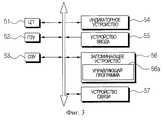
фиг.3 - блок-схему центрального блока управления, показанного на фиг.2;
фиг. 4 иллюстрирует расположение в помещении роботизированного чистящего устройства, показанного на фиг.1;
фиг. 5 изображает траекторию перемещения роботизированного чистящего устройства в помещении, показанном на фиг.4;
фиг.6 - пример карты изображения, созданной путем преобразования изображения, снимаемого по траектории перемещения, показанной на фиг.5;
фиг. 7 - блок-схему алгоритма, иллюстрирующую процесс управления роботизированным чистящим устройством в соответствии с одним предпочтительным вариантом выполнения настоящего изобретения;
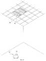
фиг.8 - еще один пример потолка помещения;
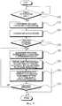
фиг. 9 - блок-схему, иллюстрирующую процесс управления роботизированным чистящим устройством в соответствии с еще одним предпочтительным вариантом выполнения настоящего изобретения.BRIEF DESCRIPTION OF THE DRAWINGS
The specified purpose and advantages of the present invention clearly follow from the description of its preferred embodiments with reference to the accompanying drawings, in which:
FIG. 1 is a perspective view of a proposed robotic cleaning device with the cover removed;
figure 2 is a block diagram of the proposed robotic cleaning device;
figure 3 is a block diagram of a Central control unit shown in figure 2;
FIG. 4 illustrates the indoor arrangement of the robotic cleaning device shown in FIG. 1;
FIG. 5 depicts the path of a robotic cleaning device in the room shown in FIG. 4;
FIG. 6 is an example of an image map created by converting an image captured along a moving path shown in FIG. 5;
FIG. 7 is a flowchart illustrating a process for controlling a robotic cleaning device in accordance with one preferred embodiment of the present invention;
Fig. 8 is another example of a room ceiling;
FIG. 9 is a flowchart illustrating a process for controlling a robotic cleaning device in accordance with yet another preferred embodiment of the present invention.
ПОДРОБНОЕ ОПИСАНИЕ ПРЕДПОЧТИТЕЛЬНЫХ ВАРИАНТОВ ВЫПОЛНЕНИЯ
Предпочтительные варианты выполнения настоящего изобретения подробно описаны ниже со ссылками на прилагаемые чертежи.DETAILED DESCRIPTION OF THE PREFERRED EMBODIMENTS
Preferred embodiments of the present invention are described in detail below with reference to the accompanying drawings.
Как показано на фиг.1 и 2, роботизированное чистящее устройство 1 содержит всасывающий узел 11, воспринимающий блок 12, переднюю камеру 13, верхнюю камеру 14, приводной узел 15, запоминающее устройство 16, передатчик 17 и контроллер 18, а также батарею 19. As shown in figures 1 and 2, the
Узел 11 установлен на главном корпусе 10а и предназначен для сбора пыли с расположенного напротив него пола при втягивании воздуха. Узел 11 может быть выполнен известным способом. В качестве примера узел 11 имеет двигатель (не показан) для создания всасывающей тяги и всасывающую камеру для сбора воздуха, втягиваемого через всасывающее отверстие или всасывающую трубу, расположенное (расположенную) напротив пола, путем приведения в действие указанного двигателя. The
Блок 12, посылающий сигнал внешнему приемнику, содержит датчик 12а обнаружения препятствий, расположенный по боковой периферии корпуса с заданными интервалами и предназначенный для приема отраженного сигнала, и датчик 12b определения дальности перемещения, предназначенный для измерения величины дальности перемещения. The
Датчик 12а имеет инфракрасные излучающие элементы 12а1, предназначенные для испускания инфракрасных лучей, и световоспринимающие элементы 12а2, предназначенные для восприятия отраженного света. Элементы 12а1 и 12а2 расположены по внешней периферии датчика 12а парами, сформированными перпендикулярно. С другой стороны, датчик 12а может включать ультразвуковой датчик, способный испускать ультразвук и воспринимать отраженный ультразвук. Датчик 12а также используется для измерения расстояния между чистящим устройством и препятствием, или стеной. The
Датчик 12b может включать датчик определения числа оборотов, предназначенный для определения числа оборотов колес 15a-15d. При этом, например, датчик определения числа оборотов может включать кодовый датчик, предназначенный соответственно для определения числа оборотов двигателей 15e-15f. The
Передняя камера 13, расположенная на главном корпусе 10а, предназначена для съемки переднего изображения и передачи снимаемого изображения на контролер 18. The
Верхняя камера 14, расположенная на корпусе 10а, предназначена для съемки верхнего изображения и передачи снимаемого изображения на контролер 18. The
Приводной узел 15 содержит два колеса 15а, 15b, расположенных спереди с обеих сторон, два колеса 15с, 15d, расположенных сзади с обеих сторон, двигатели 15е, 15f для вращения задних колес 15с, 15d и приводной ремень 15g для передачи энергии задних колес 15с, 15d на передние колеса 15а, 15b. Двигатели 15е, 15f узла 15 способны вращаться независимо в разных направлениях в соответствии с управляющим сигналом контроллера 18. Вращение может осуществляться с различным числом оборотов. The
Передатчик 17 посылает данные об объекте через антенну 17а и передает сигнал, переданный через эту антенну, на контроллер 18. The
Контроллер 18 обрабатывает сигнал, переданный передатчиком 17, и управляет каждым элементом. Контроллер 18 обрабатывает входной сигнал, полученный от клавишного устройства ввода, если такое устройство, клавиши которого предназначены для управления функциями машины, дополнительно имеется на главном корпусе 10а. The
Управляя узлом 15, контроллер 18 корректирует траекторию перемещения устройства 10 путем анализа изображения, снимаемого камерой 14, для перемещения в зоне чистки в соответствии со схемой перемещения, задаваемой командой на чистку. By controlling the
В соответствии с первым аспектом настоящего изобретения при установлении режима создания карты изображения контроллер 18 создает карту изображения с привязкой к верхней зоне с использованием изображения, снимаемого камерой 14, путем управления узлом 15 для перемещения устройства 10 в зоне чистки в соответствии с заданной схемой перемещения для создания карты и запоминает созданную карту в запоминающем устройстве 16. Контроллер 18 может быть установлен на осуществление указанного режима при поступлении сигнала выполнения этого режима извне беспроводным способом или с клавишного устройства ввода. С другой стороны, контроллер 18 может быть установлен на осуществление режима создания карты изображения перед осуществлением чистки при передаче команды на чистку извне беспроводным способом или с клавишного устройства ввода. In accordance with the first aspect of the present invention, when setting the image card creation mode, the
При работе в режиме создания карты изображения контроллер 18 управляет узлом 15 в соответствии со схемой перемещения, заданной для съемки камерой 14 зоны чистки, окруженной препятствием или стеной, другими словами, всего помещения, путем разделения этого помещения. В качестве примера схемы перемещения контроллер 18 перемещает устройство 10 вперед из текущего положения, а при обнаружении датчиком 12а стены или препятствия определяет это положение как исходное. После этого контроллер 18 выдает команду узлу 15 на перемещение устройства 10 до тех пор, пока последнее не вернется в свое исходное положение, перемещаясь вдоль стены. Затем контроллер 18 перемещает устройство 10 в пределах зоны, заданной нанесенным контуром, вдоль линии перемещения, проходящей с равными интервалами. Другими словами, контроллер 18 управляет узлом 15 для перемещения устройства 10 вдоль линии 22 перемещения, намеченной в зоне 21 чистки, заданной как показано на фиг.5. При этом интервал линии 22 задают с обеспечением последовательного получения верхних изображений. Верхнее изображение снимается при перемещении устройства 10 по линии 22. Кроме того, цикл съемки отдельного фрагмента предпочтительно задают так, чтобы величина его перекрытия с соседним из верхних изображений, снимаемых или выделяемых при перемещении, составляла от 10% до 20%. Для определения требуемого цикла съемки можно несколько раз предварительно снять ряд изображений. С другой стороны, цикл съемки заранее задают с учетом угла обзора камеры 14 и расстояния от пола до потолка в обычном помещении, а затем по каждому заданному циклу съемки может выполняться съемка. When operating in the mode of creating an image map, the
Изображение, снимаемое верхней камерой 14 в процессе перемещения, хранится в устройстве 16 как карта верхнего изображения, показанная на фиг.6, на которой все изображение сведено к установленным на потолке элементам, показанным на фиг.4, таким как электрическая лампа 31, датчик 32 пожарной сигнализации, люминесцентная лампа 33. Эта съемка осуществляется под управлением контроллера 18. The image captured by the
Предпочтительно контроллер 18 разделяет карту изображения, хранящуюся в устройстве 16, на несколько ячеек. Кроме того, контроллер 18 осуществляет обработку изображения для задания особого признака в качестве стандартной координатной точки, что позволяет без затруднения определять положение устройства 10 путем выделения на изображениях этого признака, соответствующего каждой ячейке. Например, лампа 31, датчик 32 и люминесцентная лампа 33 прямого света заданы как особые признаки для способа обработки изображения применительно к снимаемому изображению этих элементов, показанных на фиг.4. Способ обработки изображения для выделения особых признаков на снимаемом изображении может включать различные известные способы. Например, может применяться способ, при котором после перевода снимаемого изображения в полутоновое изображение обрабатывают координатную точку, рассчитанную путем соединения точек пиксел, имеющих одинаковые значения, в качестве особых признаков. Кроме того, зона изображения, имеющая распределение, схожее с величиной записанных данных, может быть задана как соответствующий особый признак после предварительного запоминания типа распределения видеоданных, относящихся к особым признакам. Preferably, the
В соответствии со вторым аспектом настоящего изобретения контроллер 18 создает карту изображения путем трехмерного преобразования переднего изображения, снимаемого передней камерой 13, и верхнего изображения, снимаемого верхней камерой 14, и запоминает созданную карту в устройстве 16. При создании и использовании трехмерной карты изображения точность определения положения может быть улучшена. В этом случае предпочтительно при определении положения сначала осуществляют определение положения исходя из верхнего изображения, имеющей меньшее разнообразие установленных элементов. Если положение точно не определено, целесообразно обратиться к переднему изображению. In accordance with a second aspect of the present invention, the
Контроллер 18 определяет положение устройства 10 с помощью карты изображения, созданной при осуществлении чистки устройством 10, после создания этой карты. Другими словами, контроллер 18 определяет текущее положение устройства 10 путем сравнения текущего изображения, полученного только от верхней камеры 14 или от обеих камер 13 и 14, с хранящейся в памяти картой изображения и при поступлении беспроводным способом извне или с клавишного устройства ввода сигнала управления чисткой управляет узлом 15 в соответствии с целевой траекторией перемещения из положения, определенного как указано выше. В данном случае сигнал управления чисткой включает выполнение наблюдения камерами 13 и 14 или чистку. Контроллер 18 вычисляет погрешность перемещения с использованием текущего положения, определенного с помощью дальности перемещения, измеренной кодовым датчиком, и сравнением текущего снимаемого изображения с хранящейся картой изображения, и управляет узлом 15 для прокладывания целевой траектории перемещения путем корректировки погрешности. The
Выше указано, что карту изображения создает непосредственно контроллер 18, а положение устройства 10 определяется им самим с использованием созданной карты изображения. It is indicated above that the image card is created directly by the
В соответствии с третьим аспектом настоящего изобретения для внешней обработки процессов создания карты верхнего изображения и определения положения устройства 10 создана роботизированная чистящая система, предназначенная для уменьшения рабочей нагрузки, необходимой для создания карты изображения устройства 10 и определения его положения. In accordance with a third aspect of the present invention, a robotic cleaning system is provided for external processing of processes for creating a top image card and determining the position of the
И наконец, устройство 10 выполнено с возможностью беспроводной передачи внешнему устройству информации о снимаемом изображении и работы в соответствии с управляющим сигналом, полученным от внешнего устройства. Кроме того, дистанционный контроллер 40 беспроводным способом управляет перемещением устройства 10, определяет его положение и создает карту изображения. Finally, the
Дистанционный контроллер 40 содержит беспроводное ретранслирующее устройство 41 и центральный блок 50 управления. The
Устройство 41 обрабатывает сигнал, переданный беспроводным способом от устройства 10, и передает по проводам обработанный сигнал блоку 50. Кроме того, беспроводное передающее устройство беспроводным способом передает сигнал, полученный от блока 50, устройству 10 посредством антенны 42. The
Блок 50 содержит обычный компьютер; пример блока 50 показан на фиг.3. Как показано на этом чертеже, блок 50 содержит ЦП (центральный процессор) 51, ПЗУ (постоянное запоминающее устройство) 52, ОЗУ (оперативное запоминающее устройство) 53, индикаторное устройство 54, устройство 55 ввода, запоминающее устройство 56 и устройство 57 связи.
Устройство 56 содержит управляющую программу 56а для управления роботизированным чистящим устройством 10 и обработки передаваемого им сигнала. The
Программа 56а имеет меню для управления устройством 10 посредством устройства 54. Программа 56а обрабатывает выбранный пользователем пункт меню, который должно выполнить устройство 10 при приведении его в действие. Предпочтительно меню включает создание карты зоны чистки, чистку и наблюдение. Кроме того, целесообразно наличие таких подменю, как создание карты изображения, список выбора целевых зон и способ чистки.
При наличии меню для создания карты зоны чистки или карты изображения предпочтительно, чтобы при осуществлении чистки устройством 10 пользователь мог устанавливать уточненный цикл на неделю или месяц для уточнения карты изображения. If there is a menu for creating a map of the cleaning zone or image map, it is preferable that when cleaning with the
При введении пользователем сигнала создания карты изображения посредством устройства 55 или во время создания исходной карты изображения программа 56а управляет устройством 10 для приема во всей зоне чистки верхнего изображения, необходимого для создания карты изображения, как описано выше. Программа 56а создает карту изображения путем преобразования изображения, переданного путем управления устройством 10, и сохраняет созданную карту в памяти устройства 56. В этом случае контроллер 18 устройства 10 управляет узлом 15 в соответствии с управляющей информацией, переданной программой 56а посредством устройства 41, и таким образом рабочая нагрузка при создании карты изображения отсутствует. Кроме того, контроллер 18 посредством устройства 41 передает верхнее изображение, снимаемое с регулярным циклом при перемещении роботизированного чистящего устройства, блоку 50. Программа 56а может создавать карту изображения путем совместного преобразования переднего изображения и верхнего изображения. When the user enters the signal to create the image card through the
Способ определения положения устройства 10, приводимого в действие, как описано выше, описан ниже со ссылкой на фиг.7. A method for determining the position of a
Прежде всего контроллер 18 выявляет необходимость осуществления режима создания карты изображения (шаг S100). First of all, the
При выявлении такой необходимости контроллер 18 приводит устройство 10 в действие для съемки всего верхнего изображения (шаг S110). When such a need is detected, the
Контроллер 18 создает карту изображения путем преобразования снимаемого камерой 14 верхнего изображения (и переднего изображения), соответствующего зоне чистки, и сохраняет созданную карту в памяти запоминающего устройства 16, 56 (шаг S120). The
Затем контроллер 18 определяет, передана ли команда на чистку (шаг S130). Then, the
При обнаружении передачи такой команды контроллер 18 определяет положение устройства 10 путем сравнения верхнего изображения, переданного верхней камерой 14, с хранящейся картой изображения (шаг S140). Если на шаге 140 карта изображения включает информацию о переднем изображении, текущее переднее изображение может также использоваться для определения положения. Upon detecting the transmission of such a command, the
Затем, в соответствии с переданной командой на чистку (шаг S150), контроллер 18 вычисляет траекторию перемещения из текущего положения, определенного как указано выше, в зону чистки или траекторию чистки. Then, in accordance with the transmitted cleaning command (step S150), the
Далее контроллер 18 перемещает устройство 10 в соответствии с вычисленной траекторией перемещения (шаг S160). Next, the
После этого контроллер 18 определяет, завершена ли работа (шаг S170). В данном случае под работой подразумевается работа по чистке, выполняемая при перемещении по траектории чистки или к целевому положению. Если контроллер определил, что работа не завершена, шаги 140-160 повторяют до тех пор, пока она не завершится. After that, the
С другой стороны, в соответствии с четвертым вариантом выполнения настоящего изобретения, если потолок имеет прямоугольный периметр, применяют способ перемещения устройства 10, позволяющий путем съемки потолка снизить нагрузку в процессе коррекции траектории перемещения. On the other hand, in accordance with a fourth embodiment of the present invention, if the ceiling has a rectangular perimeter, a method of moving the
Например, как показано на фиг.8, если потолок составлен из прямоугольных гипсокартонных листов 34 или если на потолке установлены лампы 35 прямого света, имеется возможность коррекции погрешности перемещения посредством контроллера 18 и/или дистанционного контроллера 40 путем использования особенностей потолка, заключающихся в прямолинейном контуре. For example, as shown in Fig. 8, if the ceiling is composed of
Для этого контроллер 18 выделяет линейный элемент в изображении, снимаемом верхней камерой 14 при перемещении устройства 10, с использованием известного способа обработки изображения выявленной кромки и корректирует траекторию перемещения путем использования данных о выделенном линейном элементе. For this, the
Предпочтительно контроллер 18 корректирует погрешность перемещения, определенную относительно заданного времени или заданного расстояния до кодового датчика. Затем контроллер 18 повторно корректирует погрешность перемещения путем использования линейного элемента изображения, снимаемого верхней камерой. Preferably, the
Другими словами, контроллер 18 вычисляет погрешность траектории перемещения путем ее определения кодовым датчиком и управляет узлом 15 для обеспечения возможности возвращения устройства 10 на целевую траекторию перемещения в соответствии с вычисленной погрешностью. Затем контроллер 18 корректирует погрешность перемещения путем вычисления погрешности отклонения устройства 10 от траектории с использованием информации о направлении линейного элемента, выделенного путем анализа видеоданных, снимаемых камерой 14. In other words, the
Вышеописанный способ может применяться для вышеописанной роботизированной чистящей системы. The above method can be applied to the above robotic cleaning system.
Здесь в качестве способа обработки изображения выявленной кромки могут применяться различные способы, например "Sobel Alorithm" или "Navatiark Babu Alorithm". Here, various methods can be used as the image processing method of the detected edge, for example, “Sobel Alorithm” or “Navatiark Babu Alorithm”.
Ниже со ссылкой на фиг.9 подробно описан способ управления роботизированным чистящим устройством, обеспечивающий возможность корректировки погрешности перемещения путем выделения линейного элемента в верхнем изображении верхней части помещения. Below, with reference to Fig. 9, a control method for a robotic cleaning device is described, which makes it possible to correct the movement error by highlighting a linear element in the upper image of the upper part of the room.
Прежде всего контроллер 18 выявляет необходимость выполнения режима создания карты зоны чистки (шаг S200). First of all, the
При выявлении такой необходимости контроллер 18 перемещает устройство 10 в пределах зоны чистки (шаг S210). When such a need is detected, the
Схема перемещения устройства 10 применительно к способу создания карты зоны чистки такая же, как и в вышеописанном примере. Сначала устройство 10 перемещается вперед и при обнаружении стены или препятствия датчиком 12а его положение устанавливают как исходное. Затем контроллер 18 управляет узлом 15 для перемещения устройства 10 до тех пор, пока последнее не вернется в исходное положение, перемещаясь по контуру помещения вдоль стены. После этого контроллер 18 перемещает устройство 10 в пределах зоны, определяемой контуром перемещения, вдоль линии перемещения, проходящей с заданными интервалами. Контроллер 18 создает карту зоны чистки, используя информацию о препятствии или о траектории перемещения, определенной во время описанного выше перемещения, и сохраняет эту карту в памяти (шаг S220). Следует отметить, что создание карты зоны чистки и ее сохранение в памяти осуществляют таким же способом, как и вышеописанный способ создания карты изображения. The movement pattern of the
Затем контроллер 18 определяет, передана ли команда на чистку (шаг S230). Then, the
При обнаружении передачи такой команды контроллер 18 вычисляет траекторию перемещения для перемещения в зону чистки или траекторию чистки в соответствии с переданной командой на чистку (шаг S240). Upon detection of the transmission of such a command, the
Далее контроллер 18 перемещает устройство 10 в соответствии с вычисленной траекторией перемещения (шаг S250). Next, the
Контроллер 18 выделяет линейный элемент в изображении, снимаемом верхней камерой 14 при перемещении устройства 10, и корректирует погрешность перемещения, используя данные о выделенном линейном элементе (шаг S260). Предпочтительно анализ изображения, снимаемого верхней камерой 14, выполняют при каждом цикле, заданном для снижения нагрузки при обработке изображения. The
После этого контроллер 18 определяет (шаг S270), завершена ли работа при перемещении устройства 10 с выполнением вышеописанного процесса. Если контроллер 18 определил, что работа не завершена, шаги 240-260 повторяются им до тех пор, пока устройство 10 не завершит чистку. After that, the
Как описано выше, роботизированное чистящее устройство, роботизированная чистящая система и способ управления ими в соответствии с настоящим изобретением позволяют проще выполнять управляемую по команде чистку путем уменьшения погрешности перемещения в целевое положение, поскольку устройство 10 может точнее определять свое положение благодаря использованию верхнего изображения, имеющего меньшее разнообразие установленных элементов. As described above, the robotic cleaning device, the robotic cleaning system and the method of controlling them in accordance with the present invention make it easier to carry out command-controlled cleaning by reducing the error of movement to the target position, since the
Выше проиллюстрированы и описаны предпочтительные варианты выполнения настоящего изобретения. Однако данное изобретение не ограничено указанными вариантами выполнения, и специалисты в этой области могут внести в него изменения, не выходя за пределы его сущности, изложенной в формуле изобретения. The preferred embodiments of the present invention are illustrated and described above. However, the present invention is not limited to these embodiments, and those skilled in the art can make changes thereto without departing from its spirit as set forth in the claims.
Claims (17)
Translated fromRussianApplications Claiming Priority (4)
| Application Number | Priority Date | Filing Date | Title |
|---|---|---|---|
| KR20010020754 | 2001-04-18 | ||
| KR2001-20754 | 2001-04-18 | ||
| KR2001-65888 | 2001-10-25 | ||
| KR10-2001-0065888AKR100406636B1 (en) | 2001-04-18 | 2001-10-25 | Robot cleaner and system and method of controling thereof |
Publications (2)
| Publication Number | Publication Date |
|---|---|
| RU2001133030A RU2001133030A (en) | 2003-07-10 |
| RU2220643C2true RU2220643C2 (en) | 2004-01-10 |
Family
ID=26638995
Family Applications (1)
| Application Number | Title | Priority Date | Filing Date |
|---|---|---|---|
| RU2001133030/12ARU2220643C2 (en) | 2001-04-18 | 2001-12-03 | Automatic cleaning apparatus, automatic cleaning system and method for controlling of system (versions) |
Country Status (10)
| Country | Link |
|---|---|
| US (1) | US6732826B2 (en) |
| JP (1) | JP2002325708A (en) |
| CN (1) | CN1218815C (en) |
| AU (1) | AU751807B2 (en) |
| DE (1) | DE10164278B4 (en) |
| FR (1) | FR2823868B1 (en) |
| GB (1) | GB2376537B (en) |
| NL (1) | NL1019692C2 (en) |
| RU (1) | RU2220643C2 (en) |
| SE (1) | SE520911C2 (en) |
Families Citing this family (253)
| Publication number | Priority date | Publication date | Assignee | Title |
|---|---|---|---|---|
| US8788092B2 (en) | 2000-01-24 | 2014-07-22 | Irobot Corporation | Obstacle following sensor scheme for a mobile robot |
| US8412377B2 (en) | 2000-01-24 | 2013-04-02 | Irobot Corporation | Obstacle following sensor scheme for a mobile robot |
| US6956348B2 (en) | 2004-01-28 | 2005-10-18 | Irobot Corporation | Debris sensor for cleaning apparatus |
| US7571511B2 (en) | 2002-01-03 | 2009-08-11 | Irobot Corporation | Autonomous floor-cleaning robot |
| US6690134B1 (en) | 2001-01-24 | 2004-02-10 | Irobot Corporation | Method and system for robot localization and confinement |
| US8396592B2 (en) | 2001-06-12 | 2013-03-12 | Irobot Corporation | Method and system for multi-mode coverage for an autonomous robot |
| US7429843B2 (en) | 2001-06-12 | 2008-09-30 | Irobot Corporation | Method and system for multi-mode coverage for an autonomous robot |
| US9128486B2 (en) | 2002-01-24 | 2015-09-08 | Irobot Corporation | Navigational control system for a robotic device |
| US6836701B2 (en) | 2002-05-10 | 2004-12-28 | Royal Appliance Mfg. Co. | Autonomous multi-platform robotic system |
| KR100483548B1 (en)* | 2002-07-26 | 2005-04-15 | 삼성광주전자 주식회사 | Robot cleaner and system and method of controlling thereof |
| DE10231386B4 (en)* | 2002-07-08 | 2004-05-06 | Alfred Kärcher Gmbh & Co. Kg | Sensor device and self-propelled floor cleaning device with a sensor device |
| US20060064202A1 (en)* | 2002-08-26 | 2006-03-23 | Sony Corporation | Environment identification device, environment identification method, and robot device |
| US6814171B2 (en)* | 2002-08-30 | 2004-11-09 | Motorola, Inc. | Automotive drive assistance system and method |
| US7054716B2 (en)* | 2002-09-06 | 2006-05-30 | Royal Appliance Mfg. Co. | Sentry robot system |
| US8386081B2 (en) | 2002-09-13 | 2013-02-26 | Irobot Corporation | Navigational control system for a robotic device |
| US8428778B2 (en) | 2002-09-13 | 2013-04-23 | Irobot Corporation | Navigational control system for a robotic device |
| KR100466321B1 (en)* | 2002-10-31 | 2005-01-14 | 삼성광주전자 주식회사 | Robot cleaner, system thereof and method for controlling the same |
| KR100468107B1 (en)* | 2002-10-31 | 2005-01-26 | 삼성광주전자 주식회사 | Robot cleaner system having external charging apparatus and method for docking with the same apparatus |
| KR100500842B1 (en)* | 2002-10-31 | 2005-07-12 | 삼성광주전자 주식회사 | Robot cleaner, system thereof and method for controlling the same |
| KR100561855B1 (en) | 2002-12-30 | 2006-03-16 | 삼성전자주식회사 | Robot localization system |
| KR100486505B1 (en)* | 2002-12-31 | 2005-04-29 | 엘지전자 주식회사 | Gyro offset compensation method of robot cleaner |
| KR100485696B1 (en)* | 2003-02-07 | 2005-04-28 | 삼성광주전자 주식회사 | Location mark detecting method for a robot cleaner and a robot cleaner using the same method |
| US7805220B2 (en)* | 2003-03-14 | 2010-09-28 | Sharper Image Acquisition Llc | Robot vacuum with internal mapping system |
| KR20040086940A (en) | 2003-04-03 | 2004-10-13 | 엘지전자 주식회사 | Mobile robot in using image sensor and his mobile distance mesurement method |
| KR100486737B1 (en)* | 2003-04-08 | 2005-05-03 | 삼성전자주식회사 | Method and apparatus for generating and tracing cleaning trajectory for home cleaning robot |
| KR100507926B1 (en)* | 2003-06-30 | 2005-08-17 | 삼성광주전자 주식회사 | Device for driving of robot cleaner |
| FI115414B (en)* | 2003-07-03 | 2005-04-29 | Sandvik Tamrock Oy | Arrangement for monitoring the location of the mining vehicle in the mine |
| KR20050012049A (en)* | 2003-07-24 | 2005-01-31 | 삼성광주전자 주식회사 | Robot cleaner and system thereof |
| KR20050012047A (en)* | 2003-07-24 | 2005-01-31 | 삼성광주전자 주식회사 | Robot cleaner having a rotating damp cloth |
| KR100533829B1 (en)* | 2003-07-29 | 2005-12-07 | 삼성광주전자 주식회사 | an air-cleaning robot and system thereof |
| GB2404331B (en)* | 2003-07-29 | 2005-06-29 | Samsung Gwanju Electronics Co | Robot cleaner equipped with negative-ion generator |
| KR100478681B1 (en) | 2003-07-29 | 2005-03-25 | 삼성광주전자 주식회사 | an robot-cleaner equipped with floor-disinfecting function |
| KR100520079B1 (en)* | 2003-08-01 | 2005-10-12 | 삼성전자주식회사 | robot system and control method thereof |
| KR100552691B1 (en)* | 2003-09-16 | 2006-02-20 | 삼성전자주식회사 | Method and apparatus for estimating magnetic position and azimuth of mobile robot |
| JP2005166001A (en)* | 2003-11-10 | 2005-06-23 | Funai Electric Co Ltd | Automatic dust collector |
| DE10354642A1 (en)* | 2003-11-22 | 2005-06-16 | Bayerische Motoren Werke Ag | Apparatus and method for programming an industrial robot |
| KR20050063543A (en)* | 2003-12-22 | 2005-06-28 | 엘지전자 주식회사 | Position confirmation apparatus and method for mobile robot |
| US7332890B2 (en) | 2004-01-21 | 2008-02-19 | Irobot Corporation | Autonomous robot auto-docking and energy management systems and methods |
| WO2005098476A1 (en) | 2004-03-29 | 2005-10-20 | Evolution Robotics, Inc. | Method and apparatus for position estimation using reflected light sources |
| US7617557B2 (en)* | 2004-04-02 | 2009-11-17 | Royal Appliance Mfg. Co. | Powered cleaning appliance |
| KR100544480B1 (en)* | 2004-05-12 | 2006-01-24 | 삼성광주전자 주식회사 | Automatic cleaning apparatus |
| KR20050108923A (en)* | 2004-05-14 | 2005-11-17 | 삼성광주전자 주식회사 | Mobile robot, mobile robot system and method for compensating the path thereof |
| KR100763234B1 (en)* | 2004-06-11 | 2007-10-04 | 삼성전자주식회사 | System and method for detecting driving conditions |
| KR100580301B1 (en)* | 2004-06-22 | 2006-05-16 | 삼성전자주식회사 | Air purifier and its control method |
| SG174000A1 (en) | 2004-06-24 | 2011-09-29 | Irobot Corp | Remote control scheduler and method for autonomous robotic device |
| US7706917B1 (en) | 2004-07-07 | 2010-04-27 | Irobot Corporation | Celestial navigation system for an autonomous robot |
| US11209833B2 (en) | 2004-07-07 | 2021-12-28 | Irobot Corporation | Celestial navigation system for an autonomous vehicle |
| US8972052B2 (en) | 2004-07-07 | 2015-03-03 | Irobot Corporation | Celestial navigation system for an autonomous vehicle |
| US11835343B1 (en) | 2004-08-06 | 2023-12-05 | AI Incorporated | Method for constructing a map while performing work |
| KR100677252B1 (en)* | 2004-09-23 | 2007-02-02 | 엘지전자 주식회사 | Remote monitoring system and method using robot cleaner |
| KR100560966B1 (en)* | 2004-10-12 | 2006-03-15 | 삼성광주전자 주식회사 | How to calibrate gyro sensor of robot cleaner |
| KR100600487B1 (en)* | 2004-10-12 | 2006-07-13 | 삼성광주전자 주식회사 | Coordinate correction method of robot cleaner and robot cleaner system using same |
| KR100619758B1 (en)* | 2004-11-10 | 2006-09-07 | 엘지전자 주식회사 | Motion tracking device and method of robot cleaner |
| JP4553718B2 (en)* | 2004-12-16 | 2010-09-29 | シャープ株式会社 | Ion generator |
| KR100776215B1 (en)* | 2005-01-25 | 2007-11-16 | 삼성전자주식회사 | An apparatus and method for estimating and mapping a moving object using an upstream image and a computer-readable recording medium storing a computer program controlling the apparatus |
| KR101240732B1 (en) | 2005-02-18 | 2013-03-07 | 아이로보트 코퍼레이션 | Autonomous surface cleaning robot for wet and dry cleaning |
| US7620476B2 (en) | 2005-02-18 | 2009-11-17 | Irobot Corporation | Autonomous surface cleaning robot for dry cleaning |
| US8392021B2 (en) | 2005-02-18 | 2013-03-05 | Irobot Corporation | Autonomous surface cleaning robot for wet cleaning |
| KR100633444B1 (en)* | 2005-02-24 | 2006-10-13 | 삼성광주전자 주식회사 | Robot cleaner and its control method |
| US8930023B2 (en) | 2009-11-06 | 2015-01-06 | Irobot Corporation | Localization by learning of wave-signal distributions |
| KR20060108848A (en)* | 2005-04-14 | 2006-10-18 | 엘지전자 주식회사 | Cleaning robot with wireless control and remote control system using it |
| KR100635827B1 (en)* | 2005-04-25 | 2006-10-19 | 엘지전자 주식회사 | Cleaning Robot with Depression Detection Method and Method |
| KR100624387B1 (en)* | 2005-04-25 | 2006-09-20 | 엘지전자 주식회사 | Robot system with driving range |
| EP1932333A1 (en)* | 2005-07-25 | 2008-06-18 | THILLAINAYAGAM, Vidhya Rajeswari Gowri | The multifunctional mobile scanning device |
| KR100700544B1 (en)* | 2005-08-09 | 2007-03-28 | 엘지전자 주식회사 | Robot cleaner with RF antenna |
| KR100749579B1 (en)* | 2005-09-05 | 2007-08-16 | 삼성광주전자 주식회사 | Mobile robot system having a plurality of replaceable work modules and control method thereof |
| EP2050544B1 (en)* | 2005-09-30 | 2011-08-31 | iRobot Corporation | Robot system with wireless communication by TCP/IP transmissions |
| KR100738888B1 (en)* | 2005-10-27 | 2007-07-12 | 엘지전자 주식회사 | Control device and method of a camera mounted on a robot cleaner |
| US7721829B2 (en)* | 2005-11-29 | 2010-05-25 | Samsung Electronics Co., Ltd. | Traveling robot |
| KR101300492B1 (en) | 2005-12-02 | 2013-09-02 | 아이로보트 코퍼레이션 | Coverage robot mobility |
| EP2816434A3 (en) | 2005-12-02 | 2015-01-28 | iRobot Corporation | Autonomous coverage robot |
| KR101099808B1 (en) | 2005-12-02 | 2011-12-27 | 아이로보트 코퍼레이션 | Robotic systems |
| EP2270619B1 (en) | 2005-12-02 | 2013-05-08 | iRobot Corporation | Modular robot |
| US9144360B2 (en) | 2005-12-02 | 2015-09-29 | Irobot Corporation | Autonomous coverage robot navigation system |
| TWM294295U (en)* | 2005-12-27 | 2006-07-21 | Supply Internat Co Ltd E | Self-propelled device with fast detachable dust collecting box |
| US20090044370A1 (en) | 2006-05-19 | 2009-02-19 | Irobot Corporation | Removing debris from cleaning robots |
| RU2311868C1 (en)* | 2006-05-22 | 2007-12-10 | Общество с ограниченной ответственностью ООО "Робопром" | Automatic room cleaning system |
| US8417383B2 (en) | 2006-05-31 | 2013-04-09 | Irobot Corporation | Detecting robot stasis |
| KR101297388B1 (en)* | 2006-06-16 | 2013-08-19 | 삼성전자주식회사 | Moving apparatus and method for compensating position |
| TWI308487B (en)* | 2006-12-26 | 2009-04-11 | Ind Tech Res Inst | Position-detecting system and method |
| RU2361726C2 (en)* | 2007-02-28 | 2009-07-20 | Общество С Ограниченной Ответственностью "Алгоритм-Робо" | System of controlling anthropomorphous robot and control method |
| KR101281512B1 (en)* | 2007-04-06 | 2013-07-03 | 삼성전자주식회사 | Robot cleaner and control method thereof |
| ES2571739T3 (en) | 2007-05-09 | 2016-05-26 | Irobot Corp | Autonomous compact covering robot |
| WO2008149273A2 (en)* | 2007-06-05 | 2008-12-11 | Koninklijke Philips Electronics N.V. | A system as well as a method for controlling a self moving robot |
| EP2045624A1 (en)* | 2007-10-01 | 2009-04-08 | Samsung Electronics Co., Ltd. | Ultrasonic distance sensor and robot cleaner using the same |
| KR101461185B1 (en)* | 2007-11-09 | 2014-11-14 | 삼성전자 주식회사 | Apparatus and method for building 3D map using structured light |
| KR101409987B1 (en) | 2007-12-11 | 2014-06-23 | 삼성전자주식회사 | Method and apparatus for attitude correction of mobile robot |
| KR101402273B1 (en)* | 2007-12-14 | 2014-06-02 | 삼성전자주식회사 | Apparatus and method for sensing a slip in a mobile robot |
| KR20090077547A (en)* | 2008-01-11 | 2009-07-15 | 삼성전자주식회사 | Path planning method and device of mobile robot |
| US8838268B2 (en) | 2008-01-28 | 2014-09-16 | Seegrid Corporation | Service robot and method of operating same |
| US8755936B2 (en) | 2008-01-28 | 2014-06-17 | Seegrid Corporation | Distributed multi-robot system |
| US8892256B2 (en) | 2008-01-28 | 2014-11-18 | Seegrid Corporation | Methods for real-time and near real-time interactions with robots that service a facility |
| EP2249999B1 (en)* | 2008-01-28 | 2013-03-27 | Seegrid Corporation | Methods for repurposing temporal-spatial information collected by service robots |
| JP5469097B2 (en)* | 2008-02-13 | 2014-04-09 | シーグリッド コーポレーション | Distributed multi-robot system |
| US8855819B2 (en)* | 2008-10-09 | 2014-10-07 | Samsung Electronics Co., Ltd. | Method and apparatus for simultaneous localization and mapping of robot |
| KR101553653B1 (en)* | 2009-01-07 | 2015-09-16 | 삼성전자 주식회사 | apparatus and method for detecting slip of robot |
| KR101524020B1 (en)* | 2009-03-06 | 2015-05-29 | 엘지전자 주식회사 | Progressive mapping and position correction method of robot cleaner |
| TWI388956B (en)* | 2009-05-20 | 2013-03-11 | Univ Nat Taiwan Science Tech | Mobile robot, method for planning paths of manipulating target objects thereof |
| US9037294B2 (en)* | 2009-06-12 | 2015-05-19 | Samsung Electronics Co., Ltd. | Robot cleaner and control method thereof |
| US8364309B1 (en)* | 2009-07-14 | 2013-01-29 | Bailey Bendrix L | User-assisted robot navigation system |
| DE102009041362A1 (en)* | 2009-09-11 | 2011-03-24 | Vorwerk & Co. Interholding Gmbh | Method for operating a cleaning robot |
| DE102009052629A1 (en)* | 2009-11-10 | 2011-05-12 | Vorwerk & Co. Interholding Gmbh | Method for controlling a robot |
| US8423225B2 (en)* | 2009-11-11 | 2013-04-16 | Intellibot Robotics Llc | Methods and systems for movement of robotic device using video signal |
| US8679260B2 (en) | 2009-11-11 | 2014-03-25 | Intellibot Robotics Llc | Methods and systems for movement of an automatic cleaning device using video signal |
| EP2325713B1 (en)* | 2009-11-11 | 2013-06-05 | Intellibot Robotics Llc | Methods and systems for movement of robotic device using video signal |
| KR101741583B1 (en)* | 2009-11-16 | 2017-05-30 | 엘지전자 주식회사 | Robot cleaner and controlling method thereof |
| KR20110054472A (en)* | 2009-11-17 | 2011-05-25 | 엘지전자 주식회사 | Robot cleaner and his control method |
| WO2011103198A1 (en) | 2010-02-16 | 2011-08-25 | Irobot Corporation | Vacuum brush |
| KR101081927B1 (en) | 2010-05-15 | 2011-11-09 | 주식회사 일심글로발 | Window cleaning apparatus and its movement control method |
| KR20110119118A (en) | 2010-04-26 | 2011-11-02 | 엘지전자 주식회사 | Robot cleaner, and remote monitoring system using the same |
| US9014848B2 (en)* | 2010-05-20 | 2015-04-21 | Irobot Corporation | Mobile robot system |
| JP5610870B2 (en)* | 2010-06-21 | 2014-10-22 | 三菱重工業株式会社 | Unmanned traveling vehicle guidance device and unmanned traveling vehicle guidance method |
| KR101677634B1 (en)* | 2010-07-12 | 2016-11-18 | 엘지전자 주식회사 | Robot cleaner and controlling method of the same |
| KR20120044768A (en)* | 2010-10-28 | 2012-05-08 | 엘지전자 주식회사 | Robot cleaner and controlling method of the same |
| KR101750340B1 (en)* | 2010-11-03 | 2017-06-26 | 엘지전자 주식회사 | Robot cleaner and controlling method of the same |
| US9440356B2 (en)* | 2012-12-21 | 2016-09-13 | Crosswing Inc. | Customizable robotic system |
| KR101157484B1 (en)* | 2010-12-14 | 2012-06-20 | 주식회사 대한항공 | Uav automatic recovering method |
| EP2659260B1 (en) | 2010-12-30 | 2019-11-20 | iRobot Corporation | Debris monitoring |
| KR101856502B1 (en)* | 2011-04-07 | 2018-05-11 | 엘지전자 주식회사 | Robot cleaner, remote controlling system and method of the same |
| TW201305761A (en)* | 2011-07-21 | 2013-02-01 | Ememe Robot Co Ltd | An autonomous robot and a positioning method thereof |
| US11048268B2 (en)* | 2011-08-11 | 2021-06-29 | Chien Ouyang | Mapping and tracking system for robots |
| KR101366860B1 (en)* | 2011-09-20 | 2014-02-21 | 엘지전자 주식회사 | Mobile robot and controlling method of the same |
| CN102490172B (en)* | 2011-12-05 | 2014-09-24 | 东北林业大学 | Indoor intelligent cleaning robot |
| KR20130090438A (en)* | 2012-02-04 | 2013-08-14 | 엘지전자 주식회사 | Robot cleaner |
| EP2631730B1 (en)* | 2012-02-24 | 2014-09-24 | Samsung Electronics Co., Ltd | Sensor assembly and robot cleaner having the same |
| CN103292789B (en)* | 2012-02-27 | 2015-12-09 | 联想(北京)有限公司 | A kind of localization method and electronic equipment |
| RU2560828C2 (en)* | 2012-04-19 | 2015-08-20 | Федеральное государственное бюджетное образовательное учреждение высшего профессионального образования "Воронежский государственный технический университет" | Mechatronic modular robot and method of multialternative optimisation of modules of structural synthesis automatisation of its creation |
| JP5992761B2 (en)* | 2012-08-13 | 2016-09-14 | 日本電気通信システム株式会社 | Vacuum cleaner, vacuum cleaner system, and control method of vacuum cleaner |
| ES2610755T3 (en) | 2012-08-27 | 2017-05-03 | Aktiebolaget Electrolux | Robot positioning system |
| NL2009410C2 (en)* | 2012-09-04 | 2014-03-05 | Lely Patent Nv | SYSTEM AND METHOD FOR PERFORMING AN ANIMAL-RELATED ACT. |
| KR101893152B1 (en)* | 2012-10-26 | 2018-08-31 | 엘지전자 주식회사 | robot cleaner system and a control method of the same |
| US9675226B2 (en) | 2012-10-26 | 2017-06-13 | Lg Electronics Inc. | Robot cleaner system and control method of the same |
| CN103020632B (en)* | 2012-11-20 | 2016-03-30 | 北京航空航天大学 | The method for quickly identifying of localization for Mobile Robot monumented point in a kind of indoor environment |
| CN103120573A (en)* | 2012-12-06 | 2013-05-29 | 深圳市圳远塑胶模具有限公司 | Working method and working system of intelligent cleaning robot |
| RU2572382C2 (en)* | 2013-02-12 | 2016-01-10 | Федеральное государственное бюджетное образовательное учреждение высшего профессионального образования "Воронежский государственный технический университет" | Mechatronic-modular robot and method for multi-alternative optimisation of structural synthesis automation models for creation thereof |
| RU2560829C2 (en)* | 2013-02-12 | 2015-08-20 | Федеральное государственное бюджетное образовательное учреждение высшего профессионального образования "Воронежский государственный технический университет" | Mechatronic modular robot |
| RU2556432C2 (en)* | 2013-02-12 | 2015-07-10 | Федеральное государственное бюджетное образовательное учреждение высшего профессионального образования "Воронежский государственный технический университет" | Method for multialternative optimisation of structural synthesis automation models for creating mechatronic modular robots |
| RU2572383C2 (en)* | 2013-02-12 | 2016-01-10 | Федеральное государственное бюджетное образовательное учреждение высшего профессионального образования "Воронежский государственный технический университет" | Method for multi-alternative optimisation of structural synthesis automation models for creating mechatronic modular robots |
| RU2572381C2 (en)* | 2013-02-12 | 2016-01-10 | Федеральное государственное бюджетное образовательное учреждение высшего профессионального образования "Воронежский государственный технический университет" | Mechanotronic-modular robot |
| CN103092205A (en)* | 2013-02-18 | 2013-05-08 | 福建师范大学 | Mobile robot and control method thereof based on predesigned move path |
| RU2569579C2 (en)* | 2013-04-01 | 2015-11-27 | Федеральное государственное бюджетное образовательное учреждение высшего профессионального образования "Воронежский государственный технический университет" | Mechatronic-modular robot |
| RU2560830C2 (en)* | 2013-04-01 | 2015-08-20 | Федеральное государственное бюджетное образовательное учреждение высшего профессионального образования "Воронежский государственный технический университет" | Mechatronic modular robot, and method of multialternative optimisation of models of structural synthesis automatisation of its creation |
| CN103156547B (en)* | 2013-04-11 | 2016-02-24 | 苏州益节智能科技有限公司 | Intellective dust collector |
| WO2014169943A1 (en) | 2013-04-15 | 2014-10-23 | Aktiebolaget Electrolux | Robotic vacuum cleaner |
| KR102137923B1 (en) | 2013-04-15 | 2020-07-24 | 에이비 엘렉트로룩스 | Robotic vacuum cleaner with protruding sidebrush |
| KR102061511B1 (en)* | 2013-04-26 | 2020-01-02 | 삼성전자주식회사 | Cleaning robot, home monitoring apparatus and method for controlling the same |
| CN104161487B (en)* | 2013-05-17 | 2018-09-04 | 恩斯迈电子(深圳)有限公司 | Mobile device |
| CN103271699B (en)* | 2013-05-29 | 2016-05-18 | 东北师范大学 | A kind of Smart Home clean robot |
| US10307912B2 (en) | 2013-07-15 | 2019-06-04 | Lg Electronics Inc. | Robot cleaner and method for auto-correcting 3D sensor of the robot cleaner |
| JP6406680B2 (en) | 2013-08-06 | 2018-10-17 | アルフレッド ケルヒャー エスエー ウント コンパニー カーゲー | Method for operating a floor cleaning device and floor cleaning device |
| US9170581B2 (en) | 2013-09-30 | 2015-10-27 | Crown Equipment Limited | Industrial vehicles with overhead light based localization |
| CN104655161B (en)* | 2013-11-21 | 2017-05-10 | 科沃斯机器人股份有限公司 | Distance measuring device and method of distance measuring device to find distance measuring initial point |
| US10136251B2 (en) | 2013-11-28 | 2018-11-20 | Microsoft Technology Licensing, Llc | Geofence compositions |
| KR101771869B1 (en)* | 2013-12-13 | 2017-08-25 | 도시바 라이프스타일 가부시키가이샤 | Traveling body device |
| CN105829985B (en) | 2013-12-19 | 2020-04-07 | 伊莱克斯公司 | Robot cleaning device with peripheral recording function |
| KR102118049B1 (en) | 2013-12-19 | 2020-06-09 | 엘지전자 주식회사 | robot cleaner, robot cleaner system and a control method of the same |
| US10617271B2 (en) | 2013-12-19 | 2020-04-14 | Aktiebolaget Electrolux | Robotic cleaning device and method for landmark recognition |
| US10433697B2 (en) | 2013-12-19 | 2019-10-08 | Aktiebolaget Electrolux | Adaptive speed control of rotating side brush |
| KR102116596B1 (en) | 2013-12-19 | 2020-05-28 | 에이비 엘렉트로룩스 | Robotic vacuum cleaner with side brush moving in spiral pattern |
| WO2015090405A1 (en) | 2013-12-19 | 2015-06-25 | Aktiebolaget Electrolux | Sensing climb of obstacle of a robotic cleaning device |
| US10209080B2 (en) | 2013-12-19 | 2019-02-19 | Aktiebolaget Electrolux | Robotic cleaning device |
| CN105793790B (en) | 2013-12-19 | 2022-03-04 | 伊莱克斯公司 | Prioritize cleaning areas |
| WO2015090439A1 (en) | 2013-12-20 | 2015-06-25 | Aktiebolaget Electrolux | Dust container |
| KR102158690B1 (en) | 2013-12-27 | 2020-10-23 | 엘지전자 주식회사 | robot cleaner, robot cleaner system and a control method of the same |
| CN103699136B (en)* | 2014-01-14 | 2016-08-31 | 河海大学常州校区 | Intelligent home service robot system based on the algorithm that leapfrogs and method of servicing |
| CN105595924B (en)* | 2014-06-04 | 2017-10-17 | 南通大学 | Effectively realize stair clean robot method to stair transition from stair to halfpace |
| CN104006823B (en)* | 2014-06-16 | 2017-01-18 | 成都北斗群星智能科技有限公司 | System and method for speed and distance measurement of sweeping robot based on universal wheel |
| BR112016030104A2 (en) | 2014-06-27 | 2017-08-22 | Crown Equip Corp | material handling vehicle, system for providing global location for vehicles, and method for navigating or tracking the navigation of a material handling vehicle. |
| CN106415423B (en) | 2014-07-10 | 2021-01-01 | 伊莱克斯公司 | Method for detecting a measurement error of a robotic cleaning device |
| DE102014110265A1 (en)* | 2014-07-22 | 2016-01-28 | Vorwerk & Co. Interholding Gmbh | Method for cleaning or processing a room by means of a self-moving device |
| CN104122823A (en)* | 2014-07-30 | 2014-10-29 | 上海工程技术大学 | Modularized home mobile robot platform |
| US10499778B2 (en) | 2014-09-08 | 2019-12-10 | Aktiebolaget Electrolux | Robotic vacuum cleaner |
| EP3190938A1 (en) | 2014-09-08 | 2017-07-19 | Aktiebolaget Electrolux | Robotic vacuum cleaner |
| US10660496B2 (en) | 2014-09-24 | 2020-05-26 | Samsung Electronics Co., Ltd. | Cleaning robot and method of controlling the cleaning robot |
| US9174830B1 (en) | 2014-09-29 | 2015-11-03 | Crown Equipment Limited | Industrial vehicles with point fix based localization |
| CN105652864A (en)* | 2014-11-14 | 2016-06-08 | 科沃斯机器人有限公司 | Map construction method utilizing mobile robot and work method utilizing map |
| US9744670B2 (en) | 2014-11-26 | 2017-08-29 | Irobot Corporation | Systems and methods for use of optical odometry sensors in a mobile robot |
| US9519289B2 (en) | 2014-11-26 | 2016-12-13 | Irobot Corporation | Systems and methods for performing simultaneous localization and mapping using machine vision systems |
| US9751210B2 (en) | 2014-11-26 | 2017-09-05 | Irobot Corporation | Systems and methods for performing occlusion detection |
| EP3230814B1 (en) | 2014-12-10 | 2021-02-17 | Aktiebolaget Electrolux | Using laser sensor for floor type detection |
| CN107072454A (en) | 2014-12-12 | 2017-08-18 | 伊莱克斯公司 | Side brushes and robot vacuums |
| CN107003669B (en) | 2014-12-16 | 2023-01-31 | 伊莱克斯公司 | Experience-Based Roadmap for Robotic Cleaning Equipment |
| EP3234713B1 (en) | 2014-12-16 | 2022-06-15 | Aktiebolaget Electrolux | Cleaning method for a robotic cleaning device |
| US11400595B2 (en)* | 2015-01-06 | 2022-08-02 | Nexus Robotics Llc | Robotic platform with area cleaning mode |
| KR101697857B1 (en) | 2015-04-08 | 2017-01-18 | 엘지전자 주식회사 | Moving robot and method for recognizing a location of the same |
| US11099554B2 (en) | 2015-04-17 | 2021-08-24 | Aktiebolaget Electrolux | Robotic cleaning device and a method of controlling the robotic cleaning device |
| CN104887155B (en)* | 2015-05-21 | 2017-05-31 | 南京创维信息技术研究院有限公司 | Intelligent sweeping |
| DE102015109775B3 (en) | 2015-06-18 | 2016-09-22 | RobArt GmbH | Optical triangulation sensor for distance measurement |
| EP3338151B1 (en)* | 2015-08-18 | 2024-11-20 | Nilfisk A/S | Mobile robotic cleaner |
| EP3344104B1 (en) | 2015-09-03 | 2020-12-30 | Aktiebolaget Electrolux | System of robotic cleaning devices |
| DE102015114883A1 (en) | 2015-09-04 | 2017-03-09 | RobArt GmbH | Identification and localization of a base station of an autonomous mobile robot |
| ES2667850T3 (en)* | 2015-09-22 | 2018-05-14 | Bluebotics Sa | Method of retraining and tracking virtual lines for autonomous vehicles |
| CN106569489A (en)* | 2015-10-13 | 2017-04-19 | 录可系统公司 | Floor sweeping robot having visual navigation function and navigation method thereof |
| US10180683B1 (en)* | 2015-10-29 | 2019-01-15 | Fellow Robotics Ltd. | Robotic platform configured to identify obstacles and follow a user device |
| DE102015119501A1 (en) | 2015-11-11 | 2017-05-11 | RobArt GmbH | Subdivision of maps for robot navigation |
| DE102015119865B4 (en)* | 2015-11-17 | 2023-12-21 | RobArt GmbH | Robot-assisted processing of a surface using a robot |
| CN105476553B (en)* | 2015-11-25 | 2018-09-07 | 江苏美的清洁电器股份有限公司 | Intellective dust collector |
| JP6288060B2 (en)* | 2015-12-10 | 2018-03-07 | カシオ計算機株式会社 | Autonomous mobile device, autonomous mobile method and program |
| DE102015121666B3 (en) | 2015-12-11 | 2017-05-24 | RobArt GmbH | Remote control of a mobile, autonomous robot |
| DE102016102644A1 (en) | 2016-02-15 | 2017-08-17 | RobArt GmbH | Method for controlling an autonomous mobile robot |
| JP6685755B2 (en)* | 2016-02-16 | 2020-04-22 | 東芝ライフスタイル株式会社 | Autonomous vehicle |
| US11036230B1 (en) | 2016-03-03 | 2021-06-15 | AI Incorporated | Method for developing navigation plan in a robotic floor-cleaning device |
| US10368711B1 (en) | 2016-03-03 | 2019-08-06 | AI Incorporated | Method for developing navigation plan in a robotic floor-cleaning device |
| WO2017157421A1 (en) | 2016-03-15 | 2017-09-21 | Aktiebolaget Electrolux | Robotic cleaning device and a method at the robotic cleaning device of performing cliff detection |
| EP3445534B1 (en)* | 2016-04-17 | 2020-12-02 | President and Fellows of Harvard College | Magnetic receptive sensor and optimized drawing and erasing for vertically driving robot |
| CN105962849A (en)* | 2016-05-10 | 2016-09-28 | 广西升禾环保科技股份有限公司 | Sweeper robot control platform |
| CN105955265A (en)* | 2016-05-10 | 2016-09-21 | 广西升禾环保科技股份有限公司 | Sweeping robot control platform |
| US11122953B2 (en) | 2016-05-11 | 2021-09-21 | Aktiebolaget Electrolux | Robotic cleaning device |
| CN111190419B (en) | 2016-05-19 | 2022-08-09 | 科沃斯机器人股份有限公司 | Self-moving robot, combined robot and combined robot map calling method |
| AT15526U1 (en)* | 2016-06-07 | 2017-11-15 | Tridonic Gmbh & Co Kg | Sensor arrangement for the optimized navigation of a cleaning robot |
| EP3254593B1 (en)* | 2016-06-07 | 2025-05-14 | Tridonic GmbH & Co. KG | Sensor assembly for the optimized navigation of a mobile robbot unit |
| JP7073336B2 (en) | 2016-08-05 | 2022-05-23 | ロブアート ゲーエムベーハー | How to control an autonomous mobile robot |
| JP6348947B2 (en)* | 2016-11-07 | 2018-06-27 | オリンパス株式会社 | Moving photographing apparatus, moving photographing instruction apparatus, photographing apparatus, moving photographing system, moving photographing method, and moving photographing instruction method |
| CN106695743B (en)* | 2017-02-10 | 2019-12-03 | 中国东方电气集团有限公司 | A kind of dangerization solution extraction parameter based on mobile robot assigns method |
| EP3974934A1 (en) | 2017-03-02 | 2022-03-30 | Robart GmbH | Method for controlling an autonomous mobile robot |
| KR101984101B1 (en)* | 2017-03-06 | 2019-05-30 | 엘지전자 주식회사 | Cleaner and controlling method thereof |
| KR102414676B1 (en) | 2017-03-07 | 2022-06-29 | 삼성전자주식회사 | Electronic apparatus and operating method for generating a map data |
| DE102017109219A1 (en) | 2017-04-28 | 2018-10-31 | RobArt GmbH | Method for robot navigation |
| JP6814095B2 (en)* | 2017-05-23 | 2021-01-13 | 東芝ライフスタイル株式会社 | Vacuum cleaner |
| EP3629869B1 (en) | 2017-06-02 | 2023-08-16 | Aktiebolaget Electrolux | Method of detecting a difference in level of a surface in front of a robotic cleaning device |
| DE102017112793A1 (en)* | 2017-06-09 | 2018-12-13 | Vorwerk & Co. Interholding Gmbh | Self-propelled vehicle within an environment as well as system with a vehicle and an external illumination device |
| KR101984516B1 (en)* | 2017-07-21 | 2019-05-31 | 엘지전자 주식회사 | Cleaner and controlling method thereof |
| CN109388093B (en) | 2017-08-02 | 2020-09-15 | 苏州珊口智能科技有限公司 | Robot attitude control method and system based on line feature recognition and robot |
| CN107252287A (en)* | 2017-08-02 | 2017-10-17 | 深圳星鸿云科技有限公司 | Floor cleaning machine cleaning method and system |
| CN107685049A (en)* | 2017-08-24 | 2018-02-13 | 国网黑龙江省电力有限公司信息通信公司 | The auto cleaning system and method for computer room |
| EP3687357B1 (en) | 2017-09-26 | 2024-07-10 | Aktiebolaget Electrolux | Controlling movement of a robotic cleaning device |
| US11274929B1 (en)* | 2017-10-17 | 2022-03-15 | AI Incorporated | Method for constructing a map while performing work |
| US10422648B2 (en) | 2017-10-17 | 2019-09-24 | AI Incorporated | Methods for finding the perimeter of a place using observed coordinates |
| CN107977003B (en)* | 2017-11-28 | 2020-07-31 | 深圳市杉川机器人有限公司 | Area cleaning method and device |
| CN112004645B (en) | 2017-12-19 | 2024-10-15 | 卡内基梅隆大学 | Intelligent cleaning robot |
| CN108423141B (en)* | 2018-02-05 | 2020-03-31 | 浙江大学 | An underwater working robot and its control method |
| CN110362099B (en)* | 2018-03-26 | 2022-08-09 | 科沃斯机器人股份有限公司 | Robot cleaning method, device, robot and storage medium |
| CN108849291A (en)* | 2018-07-04 | 2018-11-23 | 夏子超 | A kind of lawn fallen leaves cleaning vehicle |
| US11157016B2 (en)* | 2018-07-10 | 2021-10-26 | Neato Robotics, Inc. | Automatic recognition of multiple floorplans by cleaning robot |
| KR102705170B1 (en) | 2018-11-08 | 2024-09-12 | 삼성전자주식회사 | Robot cleaner and method for controlling thereof |
| CN109298715B (en)* | 2018-11-09 | 2021-12-07 | 苏州瑞得恩光能科技有限公司 | Robot traveling control system and traveling control method |
| CN109330501B (en)* | 2018-11-30 | 2021-11-12 | 深圳乐动机器人有限公司 | Method for cleaning ground and sweeping robot |
| CN111413960A (en)* | 2018-12-19 | 2020-07-14 | 深圳市优必选科技有限公司 | A cruise method, device and terminal device based on virtual track |
| CN109497893A (en)* | 2018-12-28 | 2019-03-22 | 湖南格兰博智能科技有限责任公司 | A kind of sweeping robot and its method for judging self-position |
| JP7319824B2 (en)* | 2019-05-16 | 2023-08-02 | 株式会社日立製作所 | moving body |
| CN110919644B (en)* | 2019-06-11 | 2022-02-08 | 远形时空科技(北京)有限公司 | Method and system for positioning interaction by using camera equipment and robot |
| US12364378B2 (en) | 2019-07-31 | 2025-07-22 | Lg Electronics Inc. | Moving robot and method of calculating moving distance of the same |
| CN114174011B (en)* | 2019-07-31 | 2024-04-19 | Lg电子株式会社 | Mobile robot |
| KR102286132B1 (en)* | 2019-07-31 | 2021-08-06 | 엘지전자 주식회사 | Artificial intelligence robot cleaner |
| KR102224638B1 (en)* | 2019-07-31 | 2021-03-05 | 엘지전자 주식회사 | Moving Robot and controlling method |
| CN110554650A (en)* | 2019-09-18 | 2019-12-10 | 创泽智能机器人股份有限公司 | Remote online monitoring robot system |
| US20210282613A1 (en)* | 2020-03-12 | 2021-09-16 | Irobot Corporation | Control of autonomous mobile robots |
| JP7447670B2 (en)* | 2020-05-15 | 2024-03-12 | トヨタ自動車株式会社 | Autonomous mobile device control system, its control method and its control program |
| CN111930131B (en)* | 2020-09-30 | 2021-01-12 | 四川中水成勘院工程物探检测有限公司 | Device and application method for obtaining graph suitable for complex environment |
| CN112230658A (en)* | 2020-10-15 | 2021-01-15 | 珠海格力电器股份有限公司 | Motion control method and device of sweeping robot and sweeping robot |
| CN112826380B (en)* | 2021-03-01 | 2022-06-21 | 南京凯诺思家具有限公司 | Intelligent-manufactured bionic sweeping robot convenient to move |
| USD1032509S1 (en) | 2021-04-23 | 2024-06-25 | Mtd Products Inc | Docking station |
| CN114468828B (en)* | 2022-01-29 | 2022-10-21 | 衡南艾迪智能科技中心 | Cleaning robot and motion control method thereof |
Citations (7)
| Publication number | Priority date | Publication date | Assignee | Title |
|---|---|---|---|---|
| EP0378298A1 (en)* | 1989-01-09 | 1990-07-18 | Black & Decker Inc. | Internal contact for a charging circuit |
| DE4340771A1 (en)* | 1993-06-08 | 1994-12-15 | Samsung Electronics Co Ltd | Automatic cleaning device |
| US5534762A (en)* | 1993-09-27 | 1996-07-09 | Samsung Electronics Co., Ltd. | Self-propelled cleaning robot operable in a cordless mode and a cord mode |
| RU2127997C1 (en)* | 1997-05-12 | 1999-03-27 | Квангджу Электроникс, Ко., Лтд. | Remote control vacuum cleaner |
| KR20000002483A (en)* | 1998-06-20 | 2000-01-15 | 배길성 | Recognizing device of cleaning zone form for robot cleaner and method thereof |
| DE19916427A1 (en)* | 1998-07-31 | 2000-03-16 | Volker Sommer | Household robots for automatic vacuuming of floor surfaces |
| GB2344748A (en)* | 1998-12-18 | 2000-06-21 | Notetry Ltd | Robotic floor cleaning device |
Family Cites Families (26)
| Publication number | Priority date | Publication date | Assignee | Title |
|---|---|---|---|---|
| DE3478824D1 (en)* | 1983-10-26 | 1989-08-03 | Automax Kk | Control system for mobile robot |
| US4947094A (en)* | 1987-07-23 | 1990-08-07 | Battelle Memorial Institute | Optical guidance system for industrial vehicles |
| US4790402A (en)* | 1987-09-28 | 1988-12-13 | Tennant Company | Automated guided vehicle |
| US4933864A (en)* | 1988-10-04 | 1990-06-12 | Transitions Research Corporation | Mobile robot navigation employing ceiling light fixtures |
| FR2637681B1 (en)* | 1988-10-12 | 1990-11-16 | Commissariat Energie Atomique | METHOD FOR MEASURING THE EVOLUTION OF THE POSITION OF A VEHICLE IN RELATION TO A SURFACE |
| US5155684A (en)* | 1988-10-25 | 1992-10-13 | Tennant Company | Guiding an unmanned vehicle by reference to overhead features |
| US5051906A (en)* | 1989-06-07 | 1991-09-24 | Transitions Research Corporation | Mobile robot navigation employing retroreflective ceiling features |
| US5530330A (en)* | 1994-03-30 | 1996-06-25 | Inco Limited | Automated guidance system for a vehicle |
| IT1267730B1 (en)* | 1994-06-14 | 1997-02-07 | Zeltron Spa | PROGRAMMABLE REMOTE CONTROL SYSTEM FOR A VEHICLE |
| US5525883A (en)* | 1994-07-08 | 1996-06-11 | Sara Avitzour | Mobile robot location determination employing error-correcting distributed landmarks |
| DE4429016A1 (en)* | 1994-08-16 | 1996-02-22 | Linde Ag | Navigating driver-less vehicles esp. of transport systems used in e.g. hangars or large hall |
| JPH08326025A (en)* | 1995-05-31 | 1996-12-10 | Tokico Ltd | Cleaning robot |
| JPH09266871A (en)* | 1996-04-03 | 1997-10-14 | Fuji Heavy Ind Ltd | Method for controlling cleaning robot |
| DE19614916A1 (en)* | 1996-04-16 | 1997-11-06 | Detlef Raupach | Floor cleaning robot vehicle for use in rooms |
| US6009359A (en)* | 1996-09-18 | 1999-12-28 | National Research Council Of Canada | Mobile system for indoor 3-D mapping and creating virtual environments |
| US5995884A (en)* | 1997-03-07 | 1999-11-30 | Allen; Timothy P. | Computer peripheral floor cleaning system and navigation method |
| US6079285A (en)* | 1997-10-01 | 2000-06-27 | Baker; Jack T. | Robotic sampler for remote sampling of liquids in a process stream |
| US5999865A (en)* | 1998-01-29 | 1999-12-07 | Inco Limited | Autonomous vehicle guidance system |
| EP0952427B1 (en)* | 1998-04-24 | 2004-03-03 | Inco Limited | Automated guided apparatus |
| US6292713B1 (en)* | 1999-05-20 | 2001-09-18 | Compaq Computer Corporation | Robotic telepresence system |
| AU1775401A (en)* | 1999-11-18 | 2001-05-30 | Procter & Gamble Company, The | Home cleaning robot |
| FI110806B (en)* | 2000-03-17 | 2003-03-31 | Sandvik Tamrock Oy | Arrangements for determining the position of unmanned mining vehicles |
| US6496754B2 (en)* | 2000-11-17 | 2002-12-17 | Samsung Kwangju Electronics Co., Ltd. | Mobile robot and course adjusting method thereof |
| KR100642072B1 (en)* | 2000-11-22 | 2006-11-10 | 삼성광주전자 주식회사 | Mobile robot system using RF module |
| KR100483548B1 (en)* | 2002-07-26 | 2005-04-15 | 삼성광주전자 주식회사 | Robot cleaner and system and method of controlling thereof |
| KR100556612B1 (en)* | 2002-06-29 | 2006-03-06 | 삼성전자주식회사 | Position measuring device and method using laser |
- 2001
- 2001-12-03RURU2001133030/12Apatent/RU2220643C2/ennot_activeIP Right Cessation
- 2001-12-27AUAU97486/01Apatent/AU751807B2/ennot_activeCeased
- 2001-12-28DEDE10164278Apatent/DE10164278B4/ennot_activeExpired - Fee Related
- 2002
- 2002-01-03NLNL1019692Apatent/NL1019692C2/ennot_activeIP Right Cessation
- 2002-01-11JPJP2002005165Apatent/JP2002325708A/enactivePending
- 2002-01-14FRFR0200373Apatent/FR2823868B1/ennot_activeExpired - Fee Related
- 2002-03-26SESE0200898Apatent/SE520911C2/enunknown
- 2002-04-02GBGB0207635Apatent/GB2376537B/ennot_activeExpired - Fee Related
- 2002-04-04USUS10/116,187patent/US6732826B2/ennot_activeExpired - Lifetime
- 2002-04-11CNCNB021059802Apatent/CN1218815C/ennot_activeExpired - Fee Related
Patent Citations (7)
| Publication number | Priority date | Publication date | Assignee | Title |
|---|---|---|---|---|
| EP0378298A1 (en)* | 1989-01-09 | 1990-07-18 | Black & Decker Inc. | Internal contact for a charging circuit |
| DE4340771A1 (en)* | 1993-06-08 | 1994-12-15 | Samsung Electronics Co Ltd | Automatic cleaning device |
| US5534762A (en)* | 1993-09-27 | 1996-07-09 | Samsung Electronics Co., Ltd. | Self-propelled cleaning robot operable in a cordless mode and a cord mode |
| RU2127997C1 (en)* | 1997-05-12 | 1999-03-27 | Квангджу Электроникс, Ко., Лтд. | Remote control vacuum cleaner |
| KR20000002483A (en)* | 1998-06-20 | 2000-01-15 | 배길성 | Recognizing device of cleaning zone form for robot cleaner and method thereof |
| DE19916427A1 (en)* | 1998-07-31 | 2000-03-16 | Volker Sommer | Household robots for automatic vacuuming of floor surfaces |
| GB2344748A (en)* | 1998-12-18 | 2000-06-21 | Notetry Ltd | Robotic floor cleaning device |
Also Published As
| Publication number | Publication date |
|---|---|
| US20020153184A1 (en) | 2002-10-24 |
| FR2823868A1 (en) | 2002-10-25 |
| CN1381340A (en) | 2002-11-27 |
| GB2376537B (en) | 2003-03-26 |
| GB2376537A (en) | 2002-12-18 |
| JP2002325708A (en) | 2002-11-12 |
| US6732826B2 (en) | 2004-05-11 |
| NL1019692A1 (en) | 2002-10-21 |
| GB0207635D0 (en) | 2002-05-15 |
| CN1218815C (en) | 2005-09-14 |
| SE520911C2 (en) | 2003-09-09 |
| AU751807B2 (en) | 2002-08-29 |
| NL1019692C2 (en) | 2003-09-29 |
| SE0200898D0 (en) | 2002-03-26 |
| FR2823868B1 (en) | 2005-08-05 |
| DE10164278B4 (en) | 2011-09-29 |
| DE10164278A1 (en) | 2002-10-31 |
Similar Documents
| Publication | Publication Date | Title |
|---|---|---|
| RU2220643C2 (en) | Automatic cleaning apparatus, automatic cleaning system and method for controlling of system (versions) | |
| RU2262878C2 (en) | Automatic vacuum cleaner | |
| KR100500842B1 (en) | Robot cleaner, system thereof and method for controlling the same | |
| US7184586B2 (en) | Location mark detecting method for robot cleaner and robot cleaner using the method | |
| RU2295704C2 (en) | Method of correcting gyroscopic pickup of robot | |
| RU2242160C1 (en) | Robot - vacuum cleaner, system for cleaning room with use of robot and method for controlling robot | |
| RU2210491C2 (en) | Mobile robot system using high-frequency module | |
| KR100437372B1 (en) | Robot cleaning System using by mobile communication network | |
| RU2236814C2 (en) | Cleaning automatic machine, robot-containing system for cleaning with use of automatic machine and automatic machine control method | |
| US10591925B2 (en) | Cleaner and controlling method thereof | |
| EP1500997B1 (en) | Mobile robot using image sensor and method for measuring moving distance thereof | |
| KR100468107B1 (en) | Robot cleaner system having external charging apparatus and method for docking with the same apparatus | |
| EP3432107A1 (en) | Cleaning robot and controlling method thereof | |
| KR20020081035A (en) | Robot cleaner and system and method of controling thereof | |
| US20050267631A1 (en) | Mobile robot and system and method of compensating for path diversions | |
| EP2286704A2 (en) | Robot cleaner system and method for controlling a robot cleaner | |
| RU2001133030A (en) | ROBOTIZED CLEANING DEVICE, ROBOTIZED CLEANING SYSTEM AND METHOD FOR MANAGING THEM | |
| JP2006344202A (en) | Mobile robot automatic charging recovery system and recovery method thereof | |
| KR100437157B1 (en) | Robot cleaner and system and method of rejoining the same with external charging apparatus | |
| KR20050111137A (en) | Robot cleaner system | |
| KR20030097554A (en) | Robot cleaner and system thereof |
Legal Events
| Date | Code | Title | Description |
|---|---|---|---|
| MM4A | The patent is invalid due to non-payment of fees | Effective date:20181204 |