RU2220184C1 - Apparatus for catching dust and gas emissions during discharge of coke ovens - Google Patents
Apparatus for catching dust and gas emissions during discharge of coke ovensDownload PDFInfo
- Publication number
- RU2220184C1 RU2220184C1RU2002108289/12ARU2002108289ARU2220184C1RU 2220184 C1RU2220184 C1RU 2220184C1RU 2002108289/12 ARU2002108289/12 ARU 2002108289/12ARU 2002108289 ARU2002108289 ARU 2002108289ARU 2220184 C1RU2220184 C1RU 2220184C1
- Authority
- RU
- Russia
- Prior art keywords
- exhaust gas
- gas pipeline
- opening
- coke
- dust
- Prior art date
Links
- 239000000571cokeSubstances0.000titleclaimsabstractdescription46
- 239000000428dustSubstances0.000titleclaimsabstractdescription26
- 238000007789sealingMethods0.000claimsabstractdescription27
- 230000001154acute effectEffects0.000claimsabstractdescription4
- 238000009434installationMethods0.000claimsdescription17
- 238000007664blowingMethods0.000claimsdescription4
- 238000005422blastingMethods0.000claims1
- 238000010791quenchingMethods0.000abstractdescription5
- 230000000171quenching effectEffects0.000abstractdescription5
- 238000012423maintenanceMethods0.000abstractdescription4
- 239000000126substanceSubstances0.000abstractdescription2
- 239000000969carrierSubstances0.000abstract1
- 230000000694effectsEffects0.000abstract1
- 229910000831SteelInorganic materials0.000description2
- 229920001971elastomerPolymers0.000description2
- 239000000806elastomerSubstances0.000description2
- 239000010959steelSubstances0.000description2
- 238000005452bendingMethods0.000description1
- 230000003137locomotive effectEffects0.000description1
- 230000000737periodic effectEffects0.000description1
- 238000009423ventilationMethods0.000description1
Images

Landscapes
- Coke Industry (AREA)
Abstract
Description
Translated fromRussianИзобретение относится к оборудованию коксовых цехов, а более конкретно к установкам для улавливания выбросов пыли и газа при разгрузке коксовых печей, и может быть использовано на коксовой стороне коксовых батарей. The invention relates to the equipment of coke shops, and more particularly to installations for collecting dust and gas emissions during unloading of coke ovens, and can be used on the coke side of coke oven batteries.
При разгрузке коксовых печей на коксовой стороне батареи происходят периодические выбросы пыли и газа, загрязняющие окружающую среду. When unloading coke ovens on the coke side of the battery, periodic emissions of dust and gas occur, polluting the environment.
Из патентной и научно-технической информации известно несколько разновидностей установок для улавливания выбросов пыли и газа при разгрузке коксовых печей, это:
- пылеотсасывающий зонт, установленный над коксонаправляющей и тушильным вагоном;
- бункер-вагон, осуществляющий прием и тушение кокса с улавливанием пыли и газа при этом;
- тушильные галереи, расположенные на коксовой стороне батареи над двересъемной машиной, тушильным вагоном и коксовой рампой;
- комбинированные установки - тушильная галерея и пылеулавливающий зонт над коксонаправляющей корзиной и тушильным вагоном.From the patent and scientific and technical information, several varieties of plants for collecting dust and gas emissions during unloading of coke ovens are known, these are:
- a dust suction umbrella mounted above the coke guide and extinguishing car;
- a hopper-wagon that receives and extinguishes coke with the capture of dust and gas in this case;
- extinguishing galleries located on the coke side of the battery above the door-lifting machine, the extinguishing car and the coke ramp;
- combined installations - a quenching gallery and a dust collecting umbrella over a coke guide basket and a quenching car.
В настоящее время в отечественной и зарубежной коксохимической промышленности широкое применение получили установки с пылеотсасывающими зонтами, устанавливаемыми над коксонаправляющей и тушильным вагоном. Currently, installations with dust suction umbrellas installed above the coke guide and extinguishing car are widely used in the domestic and foreign coke and chemical industries.
Известна, например, установка для улавливания пыли и газа при разгрузке коксовых печей, которая содержит пылеулавливающий зонт, смонтированный на тележке над коксонаправляющей корзиной, газоотводящий телескопический патрубок, неподвижная часть которого смонтирована на верхней части зонта, вытяжной магистральный трубопровод с клапанными коробками, установленный параллельно коксовой батарее, и вентиляционно-очистную систему, соединенную о вытяжным магистральным трубопроводом, который, в свою очередь, при выдаче кокса подсоединяется посредством клапанной коробки и телескопического патрубка к пылеулавливающему зонту (см. описание изобретения к патенту Японии 46-30100, кл. 17 А 312. 4 от 1968 г.). It is known, for example, an installation for collecting dust and gas during unloading of coke ovens, which contains a dust collecting umbrella mounted on a trolley above a coke guide basket, a telescopic exhaust pipe, the fixed part of which is mounted on the upper part of the umbrella, an exhaust main pipe with valve boxes mounted parallel to the coke oven a battery, and a ventilation and treatment system connected to an exhaust main pipe, which, in turn, is connected when coke is dispensed osredstvom valve box and a telescopic dust collecting pipe for an umbrella (see. DESCRIPTION OF THE INVENTION Japanese Patent 46-30100, cl. A 17 312. 4 from 1968 YG).
Недостаток этой установки заключается в ее сложной конструкции, которая недостаточно надежна в эксплуатации и требует при этом повышенных затрат. Обусловлено это наличием множества (против каждой печи) клапанных коробок, требующих сложного технического обслуживания, а также устройств для их открывания и закрывания до и после каждой выдачи кокса. The disadvantage of this installation is its complex design, which is not reliable enough in operation and at the same time requires increased costs. This is due to the presence of a plurality of valve boxes (against each furnace) that require complex maintenance, as well as devices for opening and closing them before and after each coke delivery.
Известна также установка для улавливания пыли и газа, которая частично лишена указанного недостатка (см. "Опыт работы системы беспылевой выдачи кокса на заводе Министер Штайн в ФРГ М., 1980. Экспресс-информация, ин-т "Черметинформация", серия 10, выпуск 1). Она является наиболее близкой к заявляемому изобретению как по технической сущности, так и по достигаемому результату. Also known is an installation for collecting dust and gas, which is partially devoid of this drawback (see "Experience in the dust-free coke delivery system at the Minister Stein plant in Germany, Germany, 1980. Express information, Institute Chermetinformatsiya,
Установка эта включает передвижной пылеулавливающий зонт, устанавливаемый над корзиной коксонаправляющей и тушильным вагоном, вытяжной газопровод, проложенный вдоль коксовой батареи и соединенный с отсасывающим и очистным оборудованием. Зонт подсоединен к вытяжному газопроводу с помощью патрубка, установленного на тележке, подвижной вдоль верхней части вытяжного газопровода. Сверху по всей длине вытяжной газопровод имеет расщелину, закрытую стальной сеткой, которая служит опорой для уплотняющей ленты из высокотемпературного эластомера. Указанная лента проходит вдоль всей длины вытяжного газопровода, огибая патрубок сверху, и плотно прижимается к решетке с помощью натяжного устройства, расположенного в конце вытяжного газопровода. This installation includes a mobile dust-collecting umbrella installed above the coke guide and extinguishing car basket, an exhaust gas pipeline laid along the coke oven battery and connected to the suction and treatment equipment. The umbrella is connected to the exhaust gas pipeline using a pipe mounted on a trolley movable along the upper part of the exhaust gas pipeline. From above, along the entire length, the exhaust gas pipeline has a crevice closed by a steel mesh, which serves as a support for the sealing tape made of high-temperature elastomer. The specified tape runs along the entire length of the exhaust gas pipeline, bending around the nozzle from above, and is tightly pressed to the grate using a tensioner located at the end of the exhaust gas pipeline.
Тележка патрубка оборудована валками, поднимающими и прижимающими уплотняющую ленту при движении патрубка к очередной разгружаемой коксовой печи для подключения пылеулавливающего зонта к вытяжному газопроводу. The nozzle cart is equipped with rollers raising and pressing the sealing tape when the nozzle moves to the next unloading coke oven to connect the dust collecting umbrella to the exhaust gas pipeline.
Установка с таким узлом соединения пылеулавливающего зонта с вытяжным газопроводом по сравнению с вышеописанной значительно проще по конструкции, но она также ненадежна в эксплуатации, так как в зимнее время года происходит примерзание уплотняющей ленты к стальной сетке вытяжного газопровода. Installing a dust-collecting umbrella with an exhaust gas pipeline with such a unit is much simpler in design than described above, but it is also unreliable in operation, since in the winter season the sealing tape freezes to the steel mesh of the exhaust gas pipeline.
Для исключения этого недостатка предлагалось щелевое отверстие вытяжного газопровода закрыть сверху кожухом коробчатой формы, рабочее пространство которого ограничено сверху и снизу двумя колосниковыми решетками с поперечными элементами, выполненными в виде полос, установленных под углом к горизонтали (см. описание изобретения к патенту США 4224111, кл. 202-255 от 1978 г. ). Однако эта мера также себя не оправдывает и, кроме того, увеличивает гидравлическое сопротивление вытяжного газопровода, что влечет за собой повышение мощности отсасывающего оборудования. To eliminate this drawback, it was proposed to close the slotted opening of the exhaust gas pipeline from above with a box-shaped casing, the working space of which is bounded above and below by two grate grids with transverse elements made in the form of strips installed at an angle to the horizontal (see the description of the invention to US patent 4224111, class 202-255 from 1978). However, this measure also does not justify itself and, in addition, increases the hydraulic resistance of the exhaust gas pipeline, which entails an increase in the power of the suction equipment.
Поэтому в основу данного изобретения поставлена задача усовершенствования установки для улавливания выбросов пыли и газа при разгрузке коксовых печей, в которой путем уменьшения площади контакта уплотняющей ленты с проемом вытяжного газопровода и применения средств для подрыва уплотняющей ленты обеспечивается беспрепятственный подъем уплотняющей ленты при передвижении тележки с соединительным патрубком и за счет этого повышается эксплуатационная надежность установки и снижаются при этом затраты на ее ремонт и обслуживание. Therefore, the basis of this invention is the task of improving the installation for capturing dust and gas emissions during unloading of coke ovens, in which by reducing the contact area of the sealing tape with the opening of the exhaust gas pipeline and the use of means to undermine the sealing tape, the sealing tape is freely lifted when moving the cart with the connecting pipe and due to this, the operational reliability of the installation is increased and the costs of its repair and maintenance are reduced.
Поставленная задача решается тем, что в установке для улавливания выбросов пыли и газов при разгрузке коксовых печей, включающей подвижный пылеулавливающий зонт, устанавливаемый над корзиной коксонаправляющей и тушильным вагоном, расположенный параллельно коксовой батарее вытяжной газопровод, верхняя часть которого выполнена в виде проема с колосниковой решеткой и снабжена уплотняющей лентой, закрывающей проем по всей его длине, и узел соединения пылеулавливающего зонта с вытяжным газопроводом, выполненный в виде патрубка, закрепленного на тележке, которая подвижно установлена на верхней части вытяжного газопровода и оборудована валками, поднимающими уплотняющую ленту над патрубком и прижимающих ее к проему вытяжного газопровода, согласно изобретению проем вытяжного газопровода снабжен опорными полосами для уплотняющей ленты, установленными над колосниковой решеткой по всей длине проема и равномерно по его ширине, и тележка снабжена средствами для подрыва уплотняющей ленты, установленными между пружинными валками и боковыми стенками патрубка. The problem is solved in that in the installation for collecting dust and gas emissions during unloading of coke ovens, including a movable dust-collecting umbrella mounted above the coke guide and extinguishing car, an exhaust gas pipeline located parallel to the coke oven battery, the upper part of which is made in the form of an opening with a grate and a grate and equipped with a sealing tape covering the opening along its entire length, and the connection unit of the dust-collecting umbrella with the exhaust gas pipe, made in the form of a pipe, is fixed according to the invention, the opening of the exhaust gas pipeline is equipped with supporting strips for the sealing tape installed over the grate along the entire length of the opening and the carriage is mounted on the upper part of the exhaust gas pipeline and is equipped with rollers raising the sealing tape above the nozzle and pressing it against the opening of the exhaust gas pipeline evenly across its width, and the trolley is equipped with means for blowing up the sealing tape installed between the spring rolls and the side walls of the nozzle.
Согласно изобретению средства для подрыва уплотняющей ленты могут быть выполнены в виде скребков, шарнирно закрепленных на корпусе тележки и установленных под острым углом к опорным полосам проема вытяжного газопровода. According to the invention, means for detonating the sealing tape can be made in the form of scrapers pivotally mounted on the body of the carriage and mounted at an acute angle to the support strips of the opening of the exhaust gas pipeline.
Расположение уплотняющей ленты на опорных полосах, значительно сокращающих площадь контакта уплотняющей ленты с проемом вытяжного газопровода, и наличие средств для подрыва уплотняющей ленты обеспечивают беспрепятственный подъем уплотняющей ленты при любых погодных условиях, что повышает эксплуатационную надежность установки и снижает при этом затраты на ее ремонт и обслуживание. The location of the sealing tape on the supporting strips, significantly reducing the contact area of the sealing tape with the opening of the exhaust gas pipeline, and the availability of means for blowing up the sealing tape ensure unobstructed lifting of the sealing tape in any weather conditions, which increases the operational reliability of the installation and reduces the cost of its repair and maintenance .
Принцип действия установки согласно данному изобретению объясняется более подробно ниже с помощью чертежей, на которых в качестве примера осуществления данного изобретения изображены:
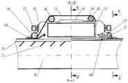
- на фиг. 1 - общий вид установки для улавливания выбросов пыли и газа при разгрузке коксовых печей, вид в плане;
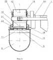
на фиг.2 - сечение по А-А на фиг.1;
- на фиг.3 - разрез по Б-Б на фиг.2;
- на фиг.4 - сечение по В-В на фиг.2;
Установка для улавливания выбросов пыли и газа при разгрузке коксовых печей (см. фиг.1) включает подвижный пылеулавливающий зонт 1, установленный над коксонаправляющей 2 двересъемной машины 3 и тушильным вагоном 4 с электровозом 5, и вытяжной газопровод 6, расположенный параллельно коксовой батарее 7 на ее коксовой стороне и соединенный с отсасывающим и очистным оборудованием 8.The principle of operation of the installation according to this invention is explained in more detail below using the drawings, in which as an example implementation of the present invention shows:
- in FIG. 1 is a general view of a plant for collecting dust and gas emissions during unloading of coke ovens, plan view;
figure 2 is a section along aa in figure 1;
- figure 3 is a section along BB in figure 2;
- figure 4 is a section along bb in figure 2;
Installation for capturing dust and gas emissions during unloading of coke ovens (see figure 1) includes a movable dust-collecting
Вытяжной газопровод 6 (см. фиг.2 и 3) в верхней части имеет проем 9, выполненный по всей его длине, и снабжен опорными полосами 10, установленными на колосниковой решетке 11 по всей длине проема и равномерно по его ширине. Проем 9 по всей длине закрыт уплотняющей лентой 12 из высокотемпературного эластомера, которая плотно прижимается к опорным полосам 10 посредством натяжного устройства (не показан), расположенного в конце вытяжного газопровода 6. The exhaust gas line 6 (see FIGS. 2 and 3) in the upper part has an opening 9 made along its entire length, and is equipped with supporting
Пылеулавливающий зонт 1 (см. фиг.4) соединен с вытяжным газопроводом 6 посредством патрубка 13, один конец которого соприкасается с проемом 9 вытяжного газопровода 6, а другой - посредством муфты 14 соединен с улавливающим зонтом 1. The dust collecting umbrella 1 (see Fig. 4) is connected to the
Патрубок 13 (см. фиг.2 и 4) закреплен на тележке 15, которая посредством ходовых роликов 16 подвижно установлена на верху вытяжного газопровода 6 над проемом 9 и соединена посредством поводков 17 с пылеулавливающим зонтом 1. The pipe 13 (see FIGS. 2 and 4) is mounted on a
Для подъема уплотняющей ленты 12 над патрубком 13 и прижима ее к опорным полосам 10 проема 9 (см. фиг.2) тележка 15 оборудована соответствующими валками 18 и 19, которые установлены в соответствующих подшипниковых узлах 20 и 21, закрепленных на тележке 15. Для беспрепятственного подъема уплотняющей ленты 12 над патрубком 13 при перемещениях тележки 15 последняя снабжена средствами для подрыва ленты 12, которые расположены между валками 19 и боковыми стенками патрубка 13 и выполнены в виде скребков 22, шарнирно закрепленных на корпусе тележки 15 и установленных под острым углом к опорным полосам 10 проема 9 вытяжного газопровода 6. To lift the
Кроме того, тележка 15 оборудована также скребками 23 (см. фиг.1 и 2) для удаления пыли или посторонних предметов с наружной поверхности уплотняющей ленты 12. In addition, the
Установка работает следующим образом. Installation works as follows.
Двересъемную машину 3 (см. фиг.1) перемещают к разгружаемой печи коксовой батареи 7, снимают дверь этой печи (не показана) и устанавливают пылеулавливающий зонт 1, коксонаправляющую 2 и тушильный вагон 4 перед этой печью. Одновременно с этим посредством поводков 17 происходит перемещение тележки 15 по верхней части вытяжного газопровода 6 (см. фиг.2), которая при этом посредством валков 18, 19 и скребков 22 беспрепятственно поднимает уплотняющую ленту 12 над патрубком 13, открывая проем 9 вытяжного газопровода 6 для соединения его с патрубком 13. Затем осуществляют выталкивание кокса, который через коксонаправляющую 2 попадает в тушильный вагон 4. При этом выбросы пыли и газа тепловым потоком поднимаются в верхнюю часть пылеулавливающего зонта 1 и через патрубок 13 и открытый проем 9 поступают в вытяжной газопровод 6, который постоянно находится под разрежением посредством отсасывающего оборудования 8. Таким образом, образуется единый тракт для удаления выбросов пыли и газа от места разгрузки кокса до очистного и отсасывающего оборудования 8. После выгрузки кокса двересъемная машина 3 устанавливает дверь в проем печи, закрывая ее, перемещается к следующей разгружаемой печи коксовой батареи 7 и цикл работы установки повторяется. A door-lifting machine 3 (see FIG. 1) is moved to a coke-oven battery 7 being discharged, the door of this furnace (not shown) is removed, and a dust collecting
Claims (2)
Translated fromRussianPriority Applications (1)
| Application Number | Priority Date | Filing Date | Title |
|---|---|---|---|
| RU2002108289/12ARU2220184C1 (en) | 2002-04-01 | 2002-04-01 | Apparatus for catching dust and gas emissions during discharge of coke ovens |
Applications Claiming Priority (1)
| Application Number | Priority Date | Filing Date | Title |
|---|---|---|---|
| RU2002108289/12ARU2220184C1 (en) | 2002-04-01 | 2002-04-01 | Apparatus for catching dust and gas emissions during discharge of coke ovens |
Publications (2)
| Publication Number | Publication Date |
|---|---|
| RU2220184C1true RU2220184C1 (en) | 2003-12-27 |
| RU2002108289A RU2002108289A (en) | 2004-09-27 |
Family
ID=32066224
Family Applications (1)
| Application Number | Title | Priority Date | Filing Date |
|---|---|---|---|
| RU2002108289/12ARU2220184C1 (en) | 2002-04-01 | 2002-04-01 | Apparatus for catching dust and gas emissions during discharge of coke ovens |
Country Status (1)
| Country | Link |
|---|---|
| RU (1) | RU2220184C1 (en) |
Cited By (1)
| Publication number | Priority date | Publication date | Assignee | Title |
|---|---|---|---|---|
| RU2426762C2 (en)* | 2006-03-03 | 2011-08-20 | Санкоук Энерджи, Инк. | Improved procedure and device for production of coke |
Citations (3)
| Publication number | Priority date | Publication date | Assignee | Title |
|---|---|---|---|---|
| US3647636A (en)* | 1970-01-19 | 1972-03-07 | Koppers Co Inc | System for collecting dust and smoke when coke is pushed from a coke oven |
| US4247370A (en)* | 1979-03-12 | 1981-01-27 | Envirotech Corporation | Coke oven fumes control system |
| SU1542951A1 (en)* | 1986-12-12 | 1990-02-15 | Gvi Proekt Predpr Koksokhimich | Installation for dust-proof discharge of coke from coke oven battery |
- 2002
- 2002-04-01RURU2002108289/12Apatent/RU2220184C1/ennot_activeIP Right Cessation
Patent Citations (3)
| Publication number | Priority date | Publication date | Assignee | Title |
|---|---|---|---|---|
| US3647636A (en)* | 1970-01-19 | 1972-03-07 | Koppers Co Inc | System for collecting dust and smoke when coke is pushed from a coke oven |
| US4247370A (en)* | 1979-03-12 | 1981-01-27 | Envirotech Corporation | Coke oven fumes control system |
| SU1542951A1 (en)* | 1986-12-12 | 1990-02-15 | Gvi Proekt Predpr Koksokhimich | Installation for dust-proof discharge of coke from coke oven battery |
Non-Patent Citations (1)
| Title |
|---|
| Экспресс-информация, вып.1//Опыт работы системы беспылевой выдачи кокса на заводе, Министер Штайн, DE, серия 10. - Коксохимическое производство, Москва, 1980.* |
Cited By (1)
| Publication number | Priority date | Publication date | Assignee | Title |
|---|---|---|---|---|
| RU2426762C2 (en)* | 2006-03-03 | 2011-08-20 | Санкоук Энерджи, Инк. | Improved procedure and device for production of coke |
Similar Documents
| Publication | Publication Date | Title |
|---|---|---|
| US4247370A (en) | Coke oven fumes control system | |
| CN201141015Y (en) | Movable coke-discharging smoke collecting device of unmanned coke furnace | |
| US4087333A (en) | Traveling hood for coke oven emission control | |
| CN109666487A (en) | A kind of closing of coke oven and ventilating dust-arrester and method | |
| RU2220184C1 (en) | Apparatus for catching dust and gas emissions during discharge of coke ovens | |
| US3933595A (en) | Oven door fume collection system | |
| CN117923298B (en) | Maintenance platform for overhauling boiler furnace | |
| CN101230279B (en) | Vehicle mounted coke oven coke-pusher smoke trapping system | |
| CN201817443U (en) | Water sealing smoke guiding main pipe device of dedusting system for coking furnace ground station | |
| CN201330259Y (en) | Blast furnace taphole-suspended lifting top-draft soot collector | |
| CN101649212B (en) | Furnace top sweeping device for tamping type coal laterally-loading and smoke-guiding car | |
| US4257849A (en) | Coke guide fumes control system | |
| UA57065C2 (en) | And installation for dust and gas blowouts trapping while unloading the coke-ovens | |
| CN206464324U (en) | A kind of dust collecting for polishing powder calcining kiln discharging opening | |
| JP4640575B2 (en) | Coke oven dust collector | |
| CN200996002Y (en) | Vehicle sided dust collector of coal oven | |
| CN209669128U (en) | A kind of coke oven coaling smoke collecting device | |
| CN109735350B (en) | Coke oven coal-charging smoke dust collecting device and method thereof | |
| KR102617271B1 (en) | Iron Oxide Dust Collection System of Combined Thermal Power Generating Plant Enable Drainage | |
| RU2787753C1 (en) | Method for dust-free issue of coke from coke furnace and device for its implementation | |
| RU2002108289A (en) | INSTALLATION FOR COLLECTING DUST AND GAS EMISSIONS WHEN UNLOADING COKE FURNACES | |
| SU1542951A1 (en) | Installation for dust-proof discharge of coke from coke oven battery | |
| CA1045575A (en) | Coke side pushing emissions control system | |
| RU2302446C2 (en) | Plant for entrapping dust emissions at production of coke | |
| KR200405158Y1 (en) | Dust collector with corrosion resistant double door |
Legal Events
| Date | Code | Title | Description |
|---|---|---|---|
| PC4A | Invention patent assignment | Effective date:20060602 | |
| MM4A | The patent is invalid due to non-payment of fees | Effective date:20090402 |