RU2213867C2 - Method of mineral mining - Google Patents
Method of mineral miningDownload PDFInfo
- Publication number
- RU2213867C2 RU2213867C2RU2000130986/03ARU2000130986ARU2213867C2RU 2213867 C2RU2213867 C2RU 2213867C2RU 2000130986/03 ARU2000130986/03 ARU 2000130986/03ARU 2000130986 ARU2000130986 ARU 2000130986ARU 2213867 C2RU2213867 C2RU 2213867C2
- Authority
- RU
- Russia
- Prior art keywords
- containers
- ore
- face
- mineral
- highway
- Prior art date
Links
Images

Landscapes
- Drilling And Exploitation, And Mining Machines And Methods (AREA)
- Excavating Of Shafts Or Tunnels (AREA)
Abstract
Description
Translated fromRussianИзобретение относится к технологии добычи полезных ископаемых, осуществляемой разработкой пород открытым способом или закрытыми разработками при прокладке выработки вертикально, наклонно или под углом к горизонту, или горизонтально. The invention relates to the technology of mining, carried out by the development of rocks by open pit mining or by closed pit mining when laying a mine vertically, obliquely or at an angle to the horizontal, or horizontally.
В настоящее время известны принципиальные направления решений реализации этой технологии, из которых наиболее представительной и наиболее близкой, по мнению заявителя, является способ добычи полезных ископаемых, включающий вскрытие массива полезного ископаемого в геологических структурах, разработку, погрузку, транспортировку руды в полость приемной камеры, ввод руды в контейнеры и их подачу по гидромагистрали, где задают положительную плавучесть контейнеру с рудой и осуществляют его выгрузку в среде атмосферы, производят возврат пустых контейнеров под загрузку (см. SU 829520 А, 25.05.1981). At present, the principal directions of solutions for the implementation of this technology are known, of which the most representative and closest, according to the applicant, is a method of mining, including opening a mineral array in geological structures, development, loading, transportation of ore into the cavity of the receiving chamber, input ore into containers and their supply through the hydraulic highway, where they set a positive buoyancy of the ore container and unload it in the atmosphere, return empty containers for loading (see SU 829520 A, 05.25.1981).
Обладая определенными преимуществами перед другими аналогами, в частности эффективной операцией вскрытия горизонта руды, этот способ имеет существенные и очевидные недостатки, заключающиеся в высоких удельных трудо- и энергозатратах на процесс разработки забоя по его эффективной площади, на процесс подачи руды в транспортирующую магистраль, возврат пустых контейнеров. Отсутствие неразрывности и непрерывности сводится к необходимости стыковки отдельных операций и процессов способа для завершения его технологической линии, что приводит к затратам дополнительного труда и времени, отражаясь на снижении эффективности всего способа. Possessing certain advantages over other analogues, in particular, the efficient operation of opening the ore horizon, this method has significant and obvious drawbacks, namely, high specific labor and energy costs for the process of developing the face along its effective area, for the process of feeding ore to the conveyor line, returning empty containers. The lack of continuity and continuity boils down to the need for joining the individual operations and processes of the method to complete its production line, which leads to the cost of additional labor and time, reflected in a decrease in the efficiency of the whole method.
Технической задачей изобретения и его техническим результатом является повышение эффективности всех операций, составляющих технологическую линию способа с получением единого непрерывного процесса от вскрытия массива породы до возврата контейнеров под загрузку, что позволяет сделать способ мобильным и автономным. The technical task of the invention and its technical result is to increase the efficiency of all operations that make up the technological line of the method with obtaining a single continuous process from opening the rock mass to returning containers for loading, which makes the method mobile and autonomous.
Поставленная задача достигается за счет того, что способ включает вскрытие массива полезного ископаемого в геологических структурах, разработку, погрузку, транспортировку руды в полость приемной камеры, ввод руды в контейнеры и их подачу по гидромагистрали, где задают положительную плавучесть контейнеру с рудой и осуществляют его выгрузку в среде атмосферы, производят возврат пустых контейнеров под загрузку. В соответствии с изобретением в массиве полезного ископаемого проходят выработку, погружают в эту выработку полую направляющую-опору в виде удлиненного полого цилиндра, на этой опоре монтируют породоразрушающий агрегат, имеющий возможность вращения вокруг направляющей-опоры с помощью подвижного бандажа, этим агрегатом ведут послойную разработку забоя в кольцевом и радиальном направлении, а после выгрузки контейнеров их возврат ведут по магистрали в среде газа, осуществляя торможение пустого контейнера за счет лобового сопротивления и перетекания воздуха снизу вверх вдоль его стенок и стенок магистрали, а по мере разработки забоя породоразрушающий агрегат перемещают вдоль образующей направляющей-опоры к забою, при этом выбор участка разработки массива ведут в кольцевом и радиальном направлениях в зависимости от содержания полезного ископаемого в массе руды. The problem is achieved due to the fact that the method includes opening an array of minerals in geological structures, developing, loading, transporting ore into the cavity of the receiving chamber, introducing ore into containers and feeding them through the hydraulic line, where they set positive buoyancy for the ore container and unload it in the atmosphere, return empty containers for loading. In accordance with the invention, a mining is carried out in a mineral array, a hollow guide-support in the form of an elongated hollow cylinder is immersed in this mine, a rock-breaking assembly is mounted on this support, which can rotate around the guide-support using a movable band, this unit conducts layer-by-layer mining of the face in the circular and radial directions, and after unloading the containers, they are returned along the highway in a gas medium, braking the empty container due to drag and air flowing from bottom to top along its walls and the walls of the highway, and as the face is developed, the rock cutting unit is moved along the generatrix of the support guide to the bottom, while the choice of the site for developing the massif is carried out in circular and radial directions depending on the mineral content in the ore mass.
Способ добычи полезных ископаемых поясняется чертежами,
где на фиг. 1 показан общий вид технологической схемы способа;
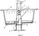
на фиг. 2 - общий вид технического оборудования и процесс разработки руды в вертикальном разрезе;
на фиг. 3 - вид в плане технического комплекса способа;
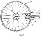
на фиг. 4 - вид сверху (в плане) скребкового пластинчатого конвейера;
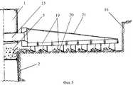
на фиг.5 - вид конвейера сбоку (в профиле).The method of mining is illustrated by drawings,
where in FIG. 1 shows a General view of the technological scheme of the method;
in FIG. 2 - a general view of technical equipment and the process of ore development in vertical section;
in FIG. 3 is a plan view of the technical complex of the method;
in FIG. 4 is a top view (in plan) of a scraper plate conveyor;
figure 5 is a side view of the conveyor (in profile).
Техническое оборудование в своем комплексе, как оно показано на упомянутых чертежах, включает полую направляющую-опору 1, представляющую собой удлиненный полый цилиндр, который погружают в пройденную выработку 2, также включает породоразрушающий агрегат 3, содержащий комбинированный рабочий орган из рабочих сопел и механических резцов (не показаны), также содержит скребковый пластинчатый конвейер 4 для забора разрушенной породы (руды). Скребковый пластинчатый конвейер 4 (фиг. 3, 4, 5) для забора разрушенной породы (руды) соединен функционально с приемной камерой 5, размещенной в полости опоры 1. The technical equipment in its complex, as shown in the aforementioned drawings, includes a hollow guide rail-
В приемной камере размещены контейнеры 6, загружаемые разработанной породой (рудой). Транспортировка этих контейнеров осуществляется в полости гидромагистрали 7 до подъема в криволинейный участок 8, который далее продолжается в одном из трех вариантов проложения: если магистраль 9 проложена горизонтально или под ничтожным углом к горизонту (не более 1o), то эта магистраль может быть заполнена рабочей жидкостью, и по ее полости контейнеры 6 транспортируют с использованием их положительной плавучести и при продувке по ходу движения контейнеров; если магистраль 9 проложена с уклоном (вниз), перемещение контейнеров ведут за счет спуска и торможения; если магистраль 9 проложена с подъемом (вверх), ее полость заполняют, как и полость начального участка гидромагистрали 7, рабочей жидкостью и контейнер подают за счет его положительной плавучести, а при малом угле подъема (до 5о) подают с продувкой по ходу перемещения контейнера. Для этого используют пневмонапорную установку 10, а подающие патрубки 11 врезают по ходу со скосом в сторону движения контейнера по магистрали 9.In the receiving chamber placed
Магистраль 9 соединена с площадкой приема 12, где в среде атмосферы осуществляют выгрузку контейнеров. После выгрузки контейнеры 13 (пустые) подают по полости обратной магистрали 14, прокладка которой в профиле также может быть в различных вариантах: горизонтально, наклонно, с подъемом, как и магистрали 9. Кроме того, один и тот же участок, как участок магистрали 9, так и участок магистрали 14, могут быть проложены и в плане и в профиле под различными углами и на таких различных участках могут быть заполнены в своих полостях как рабочей жидкостью, так и воздухом (комбинированное заполнение полости). Направляющая-опора 1 имеет подвижные бандажи 15, размещенные на ее образующей, например, с помощью роликов. С помощью этих подвижных бандажей 15 приемная камера 5 имеет возможность свободно опускаться вниз по мере углубления карьера 16 при выемке на его дне-забое породы. The
Скребковый пластинчатый конвейер 4 закреплен на направляющей-опоре 1 с помощью подвижного бандажа 15, который обеспечивает перемещение конвейера 4 в двух направлениях: относительно оси направляющей-опоры 1 и относительно ее образующей - вращение вокруг опоры (момент "М"). Конвейер 4 имеет приводные барабаны 17 и 18, между которыми и обегая их натянут пластинчатый конвейер 19 из отдельных соединенных между собой с помощью шарниров пластин. На пластинах закреплены резцы 20 (фиг. 4, 5) со скосом в плане так, что при разработке руды на забое карьера 16 руда перемещается к центру карьера и попадает в приемную камеру 5 направляющей-опоры 1, где производят загрузку руды в контейнеры. The
Описываемый способ осуществляют предварительным образованием выработки 2, в полость ее погружают направляющую-опору 1 и на ее наружной стороне с помощью подвижного бандажа 15 монтируют приемную камеру 5 и породоразрушающий агрегат 3, а также монтируют конвейер 4 с их штатными силовыми приводами (детали приводов на чертеже не показаны). Производят включение и проверку всех магистралей: 7, 14, 8, 9. С помощью породоразрушающего агрегата 3 ведут разработку породы заданным слоем разрушения, а конвейером 4 подбирают этот разрушенный слой породы и подают ее в приемную камеру 5 для загрузки контейнеров 6. The described method is carried out by preliminary formation of the
Контейнеры 6 загружают из расчета сохранения ими положительной плавучести в среде рабочей жидкости, в которую их вводят за счет подачи в полость гидромагистрали 7, где контейнеры всплывают, проходят участок 8 и входят в магистраль 9, подача по которой, как описано выше, может осуществляться одним из трех вариантов: за счет той же положительной плавучести, за счет плавучести с дополнительной подачей напорного воздуха по ходу движения контейнера, за счет только подаваемого напорного воздуха в направлении к площадке 12 приема и выгрузки контейнеров, откуда пустые контейнеры подают по магистрали 14. При этом используют также один из трех указанных вариантов (или совокупный комбинированный на участках магистрали) подачи контейнеров 13: в среде рабочей жидкости, или в среде воздуха, или в среде жидкости с продувкой воздухом по ходу контейнера. А спуск контейнеров на вертикальном участке магистрали 14 наиболее эффективно осуществлять в воздушной среде при пневмоторможении контейнеров в данном ограниченном участке магистрали за счет развитого лобового сопротивления по площади миделя контейнера и постепенного перетекания воздуха снизу вверх вдоль его стенок и стенок магистрали 14 на этом участке спуска контейнеров под загрузку.
Таким образом, разработанный способ добычи полезных ископаемых обладает универсальной и оригинальной технологической схемой осуществления всех его последовательно производимых операций, что позволяет организовать замкнутую схему от разработки до подачи разработанной руды на переработку, сделать процесс полностью автономным при возможности его автоматизации (при безлюдной технологии), что особенно важно при разработке карьеров в отдаленных от населенных пунктов регионах. Thus, the developed method of mining has a universal and original technological scheme for the implementation of all its sequentially performed operations, which allows you to organize a closed circuit from development to the supply of developed ore for processing, to make the process completely autonomous if it can be automated (with unmanned technology), which especially important when developing quarries in regions remote from human settlements.
При осуществлении данного способа возможна кольцевая разработка забоя (дна карьера 16) с образованием равномерно радиальной выработки карьера, а также возможны выборочное разрушение и выборочный забор породы при наличии более богатой руды на локальных участках, что, возможно, вести при мобильной схеме породоразрушающего агрегата (его раздвижке и укорочении) и при такой же мобильной конструкции забирающего руду конвейера. In the implementation of this method, it is possible to annularly develop a face (bottom of a pit 16) with the formation of a uniformly radial excavation of the pit, as well as possible selective destruction and selective sampling of the rock in the presence of richer ore in local areas, which may be carried out with a mobile scheme of the rock cutting unit (it sliding and shortening) and with the same mobile design of the ore-picking conveyor.
Claims (1)
Translated fromRussianPriority Applications (1)
| Application Number | Priority Date | Filing Date | Title |
|---|---|---|---|
| RU2000130986/03ARU2213867C2 (en) | 2000-12-14 | 2000-12-14 | Method of mineral mining |
Applications Claiming Priority (1)
| Application Number | Priority Date | Filing Date | Title |
|---|---|---|---|
| RU2000130986/03ARU2213867C2 (en) | 2000-12-14 | 2000-12-14 | Method of mineral mining |
Publications (2)
| Publication Number | Publication Date |
|---|---|
| RU2000130986A RU2000130986A (en) | 2002-11-10 |
| RU2213867C2true RU2213867C2 (en) | 2003-10-10 |
Family
ID=31988047
Family Applications (1)
| Application Number | Title | Priority Date | Filing Date |
|---|---|---|---|
| RU2000130986/03ARU2213867C2 (en) | 2000-12-14 | 2000-12-14 | Method of mineral mining |
Country Status (1)
| Country | Link |
|---|---|
| RU (1) | RU2213867C2 (en) |
Cited By (2)
| Publication number | Priority date | Publication date | Assignee | Title |
|---|---|---|---|---|
| RU2409734C2 (en)* | 2008-12-04 | 2011-01-20 | Миннибаев Эдуард Файзиевич | Device for well hole making with working face |
| RU2509881C1 (en)* | 2012-07-05 | 2014-03-20 | Закрытое акционерное общество "Инновационный центр "С & С" | Well recovery method |
Citations (5)
| Publication number | Priority date | Publication date | Assignee | Title |
|---|---|---|---|---|
| US3975053A (en)* | 1973-12-03 | 1976-08-17 | Kochanowsky Boris J | Mining methods as such and combined with equipment |
| US4103972A (en)* | 1973-12-03 | 1978-08-01 | Kochanowsky Boris J | Open pit mine |
| SU1247539A1 (en)* | 1985-02-15 | 1986-07-30 | Московский Геологоразведочный Институт Им.Серго Орджоникидзе | Method of combination mining of steep ore bodies |
| SU1594108A1 (en)* | 1988-08-02 | 1990-09-23 | Московский Горный Институт | Installation for hoisting cargo in containers from well |
| SU1723323A1 (en)* | 1990-04-18 | 1992-03-30 | Красноярский институт цветных металлов им.М.И.Калинина | Open-pit transport system |
- 2000
- 2000-12-14RURU2000130986/03Apatent/RU2213867C2/ennot_activeIP Right Cessation
Patent Citations (5)
| Publication number | Priority date | Publication date | Assignee | Title |
|---|---|---|---|---|
| US3975053A (en)* | 1973-12-03 | 1976-08-17 | Kochanowsky Boris J | Mining methods as such and combined with equipment |
| US4103972A (en)* | 1973-12-03 | 1978-08-01 | Kochanowsky Boris J | Open pit mine |
| SU1247539A1 (en)* | 1985-02-15 | 1986-07-30 | Московский Геологоразведочный Институт Им.Серго Орджоникидзе | Method of combination mining of steep ore bodies |
| SU1594108A1 (en)* | 1988-08-02 | 1990-09-23 | Московский Горный Институт | Installation for hoisting cargo in containers from well |
| SU1723323A1 (en)* | 1990-04-18 | 1992-03-30 | Красноярский институт цветных металлов им.М.И.Калинина | Open-pit transport system |
Cited By (2)
| Publication number | Priority date | Publication date | Assignee | Title |
|---|---|---|---|---|
| RU2409734C2 (en)* | 2008-12-04 | 2011-01-20 | Миннибаев Эдуард Файзиевич | Device for well hole making with working face |
| RU2509881C1 (en)* | 2012-07-05 | 2014-03-20 | Закрытое акционерное общество "Инновационный центр "С & С" | Well recovery method |
Similar Documents
| Publication | Publication Date | Title |
|---|---|---|
| US4103972A (en) | Open pit mine | |
| WO2019051569A1 (en) | Method for underground mining of minerals | |
| CN102996131A (en) | Solid-filling coal mining method with two pre-excavating tunnels for advancing | |
| US3440824A (en) | Method and apparatus for backfilling and underpinning an underground coal or ore mine | |
| CN109899070B (en) | Non-solid waste filling mining method for gently inclined medium-thick ore bodies based on ellipsoid drawing structure | |
| CN116025355A (en) | Coal mining method for mining extremely thin coal seam | |
| US3870373A (en) | Underground coal slurry concentrating sump | |
| US4280732A (en) | Method and apparatus for mining | |
| CN114893184B (en) | A new method of mechanized layered filling mining for thin to medium-thick ore veins | |
| WO2025162327A1 (en) | Carbon-negative backfill mining method using gangue high-porosity material | |
| US2298599A (en) | Block cave mining method and plant | |
| RU2213867C2 (en) | Method of mineral mining | |
| US4232904A (en) | Method and apparatus for deep mining using chain driven in fixed direction | |
| CN112081591A (en) | A backfill mining method and application of steeply inclined coal seam | |
| RU2158826C2 (en) | Method of mine construction for small kimberlite pipes by means of self-propelled mining machinery and complex for its lowering and lifting and ore delivery to surface | |
| RU2135772C1 (en) | Method for development of kimberlite pipes by mechanized complex | |
| RU2247241C1 (en) | Method for extraction of mineral resources | |
| RU2603992C1 (en) | Method of mined-out space filling | |
| RU2733759C1 (en) | Open-underground method of development of stratified deposits of minerals | |
| EA013438B1 (en) | Method of opencast mining of minerals and working area complex therefor | |
| RU2101498C1 (en) | Method of underground mineral mining | |
| RU2096617C1 (en) | Method for development of mineral deposits | |
| RU2091583C1 (en) | Method of mining of mineral upper horizons | |
| RU2136887C1 (en) | Powered complex for mining kimberlite | |
| CA1064528A (en) | Open pit mine |
Legal Events
| Date | Code | Title | Description |
|---|---|---|---|
| MM4A | The patent is invalid due to non-payment of fees | Effective date:20031215 |