RU2212763C2 - Open optical communication system - Google Patents
Open optical communication systemDownload PDFInfo
- Publication number
- RU2212763C2 RU2212763C2RU2001122893/09ARU2001122893ARU2212763C2RU 2212763 C2RU2212763 C2RU 2212763C2RU 2001122893/09 ARU2001122893/09 ARU 2001122893/09ARU 2001122893 ARU2001122893 ARU 2001122893ARU 2212763 C2RU2212763 C2RU 2212763C2
- Authority
- RU
- Russia
- Prior art keywords
- optical
- communication system
- base station
- lens
- optical communication
- Prior art date
Links
Images


Classifications
- H—ELECTRICITY
- H04—ELECTRIC COMMUNICATION TECHNIQUE
- H04B—TRANSMISSION
- H04B10/00—Transmission systems employing electromagnetic waves other than radio-waves, e.g. infrared, visible or ultraviolet light, or employing corpuscular radiation, e.g. quantum communication
- H04B10/11—Arrangements specific to free-space transmission, i.e. transmission through air or vacuum
- H04B10/114—Indoor or close-range type systems
- H04B10/1149—Arrangements for indoor wireless networking of information
Landscapes
- Engineering & Computer Science (AREA)
- Computing Systems (AREA)
- Physics & Mathematics (AREA)
- Electromagnetism (AREA)
- Computer Networks & Wireless Communication (AREA)
- Signal Processing (AREA)
- Optical Communication System (AREA)
- Optical Couplings Of Light Guides (AREA)
Abstract
Description
Translated fromRussianИзобретение относится к системам открытой оптической связи и может быть использовано для двусторонней передачи информации между удаленными друг от друга объектами без использования проводов и/или оптических волокон, в том числе при большом числе объектов, участвующих в обмене информацией, например при организации обмена по схеме "точка-многоточка", то есть при двустороннем обмене информацией между одной базовой станцией и несколькими абонентскими станциями. The invention relates to open optical communication systems and can be used for two-way transmission of information between objects remote from each other without the use of wires and / or optical fibers, including with a large number of objects involved in the exchange of information, for example, when organizing an exchange according to the scheme point-to-multipoint ", that is, in a two-way exchange of information between one base station and several subscriber stations.
Ключевыми компонентами систем, выполненных по принципу "точка-многоточка", являются передатчики, излучающие в нескольких заданных направлениях отдельные друг от друга оптические пучки, промодулированные, в общем случае, различными передаваемыми сигналами, и приемники на основе фотодетекторов для раздельного приема оптических сигналов, приходящих с разных направлений. Системы открытой оптической связи, работающие по схеме "точка-многоточка", обладают существенными преимуществами перед системами, в которых оптические приемники и/или передатчики выполнены по многоканальному принципу, то есть в виде набора отдельных однотипных каналов, работающих по схеме "точка-точка". Применение многоканального принципа построения систем открытой оптической связи увеличивает массу, габариты и стоимость системы примерно во столько раз, сколько направлений (отдельных световых пучков) необходимо реализовать для организации связи, так как в каждом однотипном канале содержатся все элементы и узлы, необходимые для обеспечения связи, в том числе те, которые в системах типа "точка-многоточка" представлены в единственном экземпляре и используются для обеспечения работы всех каналов. The key components of point-to-multipoint systems are transmitters that emit optical beams that are separate from each other in several specified directions, modulated, in the general case, by various transmitted signals, and photodetector based receivers for separate reception of optical signals arriving from different directions. Open optical communication systems operating on a point-to-multipoint scheme have significant advantages over systems in which optical receivers and / or transmitters are designed according to a multi-channel principle, that is, in the form of a set of separate single-type channels operating on a point-to-point basis . The use of the multichannel principle of constructing open optical communication systems increases the mass, dimensions and cost of the system approximately as many times as the directions (of individual light beams) need to be implemented for communication, since each channel of the same type contains all the elements and nodes necessary to ensure communication, including those that are presented in a single copy in point-to-multipoint systems and are used to ensure the operation of all channels.
Известна система открытой оптической связи, (см. описание к патенту Великобритании 2180116, Н 04 В 9/00, 1987 [1]). Эта система выполнена в виде нескольких фотодетекторов и нескольких излучателей, размещенных на криволинейной поверхности, например полусфере. Недостатками известной системы являются: сложность юстировки излучателей по отношению к соответствующему каждому из них приемнику; ограниченность применения, заключающаяся в небольшой дальности связи из-за больших энергопотерь, обусловленных расходимостью световых лучей излучателей. При увеличении дальности связи указанные потери приводят к необходимости сужать полосу принимаемых частот, поскольку полоса частот, в которой возможна надежная работа канала тем уже, чем слабее оптическое излучение, улавливаемое фотодетектором. A known system of open optical communication, (see the description of the patent of Great Britain 2180116, N 04 In 9/00, 1987 [1]). This system is made in the form of several photodetectors and several emitters placed on a curved surface, such as a hemisphere. The disadvantages of the known system are: the difficulty of aligning the emitters with respect to the respective receiver for each of them; limited application, consisting in a small communication range due to large energy losses due to the divergence of the light rays of the emitters. With an increase in the communication range, these losses lead to the need to narrow the band of received frequencies, since the frequency band in which reliable operation of the channel is possible is the narrower the weaker the optical radiation captured by the photodetector.
Известна система открытой оптической связи, описанная в патенте США 5909296, НКИ 359-152, 1999 [2]. Эта система содержит излучатели со средствами модуляции светового пучка и один или несколько приемников оптического излучения со средствами демодуляции. Для уменьшения расходимости пучков каждый из излучателей снабжен микролинзой. Излучатели выполнены неподвижными относительно этих линз, что исключает возможность коррекции ширины и направления луча при изменении расстояния или угла между приемной и передающей станциями. Поэтому, несмотря на уменьшение расходимости световых лучей за счет применения линз, эффективность системы во многих случаях оказывается малой. A known system of open optical communication, described in US patent 5909296, NKI 359-152, 1999 [2]. This system comprises emitters with means for modulating the light beam and one or more optical radiation receivers with demodulation means. To reduce the beam divergence, each of the emitters is equipped with a microlens. The emitters are made stationary relative to these lenses, which eliminates the possibility of correcting the width and direction of the beam when changing the distance or angle between the receiving and transmitting stations. Therefore, despite the decrease in the divergence of light rays due to the use of lenses, the efficiency of the system in many cases is small.
Из описания к патенту США 3713163 [3] известна система связи с множеством движущихся объектов. Эта система содержит излучатели и приемники, размещенные в параксиальной области на фокальной поверхности единого фокусирующего устройства, например параболического отражателя или линзы. Несколько излучателей и приемников выполнены с возможностью их вращения вокруг оси фокусирующего устройства, что обеспечивает их нацеливание на требуемый объект. Недостатком этой системы является применение фокусирующего устройства с узким полем зрения, что ограничивает телесный угол, в пределах которого могут перемещаться множественные объекты, параксиальной областью. From the description of US patent 3713163 [3] known communication system with many moving objects. This system contains emitters and receivers located in the paraxial region on the focal surface of a single focusing device, such as a parabolic reflector or lens. Several emitters and receivers are made with the possibility of their rotation around the axis of the focusing device, which ensures their aiming at the desired object. The disadvantage of this system is the use of a focusing device with a narrow field of view, which limits the solid angle, within which multiple objects can move, to the paraxial region.
Наиболее близкой к заявляемой по своей технической сущности и достигаемому результату является система открытой оптической связи, известная из описания к заявке на изобретение WO 00/48338, Н 04 В 10/70, 10/26, 2000 [4]. Предложенная в [4] система, при ее реализации для двусторонней связи, содержит множество излучателей и множество фотодетекторов, размещенных в фокальной поверхности коллективной линзовой системы базовой приемопередающей станции с широким угловым полем зрения, а также излучатели и фотодетекторы, смонтированные на нескольких удаленных абонентских станциях. В соответствии с описанием [4] на базовой приемопередающей станции передаваемые и принимаемые пучки оптического излучения проходят через одну и ту же линзовую систему, которая используется как в качестве коллективной оптической антенны, обеспечивающей концентрацию на фотодетекторах предназначенного им излучения, так и в качестве коллимирующего устройства, уменьшающего расходимость пучков, испускаемых излучателями. Closest to the claimed in its technical essence and the achieved result is an open optical communication system, known from the description of the patent application WO 00/48338, H 04
Недостатками указанной системы связи являются следующие. Во-первых, применение в приемной и в передающей оптических схемах совместно используемого элемента (в данном прототипе - линзовой системы) требует совмещения в пространстве (или, по крайней мере, оптического совмещения) излучателя и фотодетектора, обеспечивающих двустороннюю связь базовой станции с одной и той же абонентской станцией. Для обеспечения возможности указанного совмещения в пространстве излучатель и фотодетектор должны иметь размер, меньший кружка рассеяния линзовой системы, что, вообще говоря, сложно осуществить и может потребовать значительных затрат. The disadvantages of this communication system are as follows. Firstly, the use of a shared element (in this prototype, a lens system) in the receiving and transmitting optical circuits requires the combination in space (or at least optical alignment) of the emitter and photodetector, providing two-way communication of the base station with one and the same the same subscriber station. To ensure the possibility of this combination in space, the emitter and photodetector must have a size smaller than the circle of scattering of the lens system, which, generally speaking, is difficult to implement and may require significant costs.
Оптическое совмещение, когда с помощью светоделителя в пространстве совмещаются зеркальные отражения излучателя и фотодетектора, также требует дополнительных затрат. Кроме того, при высокой плотности размещения излучателей и фотодетекторов, требования, предъявляемые к компактности светоделителей, могут оказаться технически не реализуемыми. Во-вторых, линзовая система, предложенная в известной системе связи [4], состоит из линзы с широким полем зрения и второй, "фокусирующей" (по терминологии авторов [4]), линзы. Спецификой таких линзовых систем является то, что у них входной зрачок существенно меньше диаметра первой линзы. В результате, для достижения обычного в практических приложениях диаметра зрачка 50-150 мм может потребоваться использование первой линзы с диаметром, который, вообще говоря, во много раз больше требуемого зрачка. Optical alignment, when using a beam splitter in space the mirror reflections of the emitter and photodetector are combined, also requires additional costs. In addition, with a high density of emitters and photodetectors, the requirements for compact beamsplitters may not be technically feasible. Secondly, the lens system proposed in the well-known communication system [4] consists of a lens with a wide field of view and a second “focusing” (according to the terminology of the authors of [4]) lenses. The specificity of such lens systems is that their entrance pupil is significantly smaller than the diameter of the first lens. As a result, in order to achieve a pupil diameter of 50-150 mm, which is usual in practical applications, it may be necessary to use a first lens with a diameter that, generally speaking, is many times larger than the required pupil.
Линзовые системы большого (200 мм и более) диаметра являются чрезвычайно дорогостоящими, кроме того, их применение может потребовать увеличения габаритов и веса базовой станции до неприемлемых величин. К этому выводу приводят следующие соображения. Во-первых, широкоугольные объективы характеризуются соотношением D/F≥1, где D - диаметр объектива, a F - его фокусное расстояние. Во-вторых, известно, что для многолинзовых систем
где d - диаметр зрачка, γ - угловая ширина поля зрения, а параметр С для различных систем лежит в пределах 0,22-0,24 (см. Д.С. Волосов. Фотографическая оптика. М.: Искусство, 1978, с.296 [5]). Из вышеприведенных соотношений следует, что
При γ=120o и F=150 мм это выражение дает D/d>10.Lens systems of large (200 mm or more) diameter are extremely expensive, in addition, their use may require an increase in the size and weight of the base station to unacceptable values. The following considerations lead to this conclusion. Firstly, wide-angle lenses are characterized by the ratio D / F≥1, where D is the diameter of the lens, and F is its focal length. Secondly, it is known that for multi-lens systems
where d is the diameter of the pupil, γ is the angular width of the field of view, and the parameter C for various systems lies in the range 0.22-0.24 (see D.S. Volosov. Photographic optics. M: Art, 1978, p. 296 [5]). From the above relations it follows that
When γ = 120o and F = 150 mm, this expression gives D / d> 10.
Таким образом, в широкоугольной многолинзовой системе диаметр по крайней мере одной линзы на порядок превосходит диаметр зрачка, что ведет к увеличению габаритов и веса станции. Это увеличение может стать совершенно неприемлемым, если попытаться достичь необходимых для обычных практических приложений значений d=50-150 мм. Thus, in a wide-angle multi-lens system, the diameter of at least one lens exceeds the diameter of the pupil by an order of magnitude, which leads to an increase in the dimensions and weight of the station. This increase can become completely unacceptable if you try to achieve the values d = 50-150 mm necessary for ordinary practical applications.
Заявляемое изобретение направлено на увеличение дальности, скорости и надежности связи и снижение веса, габаритов и стоимости системы связи. The claimed invention is aimed at increasing the range, speed and reliability of communication and reducing the weight, dimensions and cost of the communication system.
Указанный результат достигается тем, что система открытой оптической связи содержит несколько абонентских приемопередающих станций с оптическими излучателями, средствами модуляции и фотодетекторами и базовую станцию, содержащую несколько излучателей со средствами модуляции, и приемное устройство в виде нескольких фотодетекторов и широкоугольного объектива, при этом указанный объектив выполнен в виде одной линзы и оптически связан только с фотодетекторами, а излучатели базовой станции снабжены индивидуальными устройствами формирования оптического пучка, не имеющими общих оптических элементов с объективом приемного устройства и с устройствами формирования оптического пучка других излучателей базовой станции. This result is achieved by the fact that the open optical communication system contains several subscriber transceiver stations with optical emitters, modulation means and photodetectors, and a base station containing several emitters with modulation means, and a receiving device in the form of several photodetectors and a wide-angle lens, while this lens is made in the form of a single lens and is optically connected only with photodetectors, and the emitters of the base station are equipped with individual devices forming optical beam, which do not have common optical elements with the lens of the receiving device and with devices for forming the optical beam of other emitters of the base station.
Указанный результат достигается тем, что объектив приемного устройства выполнен в виде шара, с показателем преломления n, который удовлетворяет условию 1<n≤2. The specified result is achieved by the fact that the lens of the receiving device is made in the form of a ball, with a refractive index n, which satisfies the
Указанный результат достигается тем, что объектив приемного устройства выполнен в виде набора концентрических слоев сферической формы, изготовленных из оптических материалов с разными показателями преломления так, что сферическая фокальная поверхность этого объектива имеет радиус кривизны
Rф≥Rо,
где Rф - радиус кривизны фокальной поверхности объектива;
Ro - радиус кривизны внешней поверхности объектива.This result is achieved by the fact that the lens of the receiving device is made in the form of a set of concentric layers of a spherical shape made of optical materials with different refractive indices so that the spherical focal surface of this lens has a radius of curvature
Rf ≥Rabout
where Rf is the radius of curvature of the focal surface of the lens;
Ro is the radius of curvature of the outer surface of the lens.
Указанный результат достигается тем, что устройство формирования оптического пучка выполнено по крайней мере из одного фокусирующего элемента. This result is achieved in that the optical beam forming apparatus is made of at least one focusing element.
Указанный результат достигается тем, что устройство формирования оптического пучка выполнено в виде телескопа. The specified result is achieved in that the optical beam forming device is made in the form of a telescope.
Указанный результат достигается тем, что элементы устройства формирования оптического пучка и соответствующий излучатель выполнены с возможностью их перемещения относительно друг друга. The specified result is achieved in that the elements of the optical beam forming device and the corresponding emitter are made with the possibility of their movement relative to each other.
Указанный результат достигается тем, что устройство формирования оптического пучка снабжено не менее чем двумя клиновидными пластинами из прозрачного для этого пучка материала, установленными на пути распространения пучка и выполненными с возможностью поворота каждой из них вокруг оси пучка. The indicated result is achieved in that the optical beam forming device is provided with at least two wedge-shaped plates of material transparent for this beam, mounted on the beam propagation path and configured to rotate each of them around the axis of the beam.
Указанный результат достигается тем, что устройство формирования оптического пучка снабжено светофильтром и/или ослабителем излучения, установленными на пути распространения пучка и выполненными с возможностью ступенчатого или плавного изменения их пропускания. The specified result is achieved by the fact that the optical beam forming device is equipped with a light filter and / or radiation attenuator installed on the beam propagation path and configured to stepwise or smoothly change their transmission.
Указанный результат достигается тем, что по крайней мере один излучатель снабжен световодом, через который проходит оптическое излучение на пути от излучателя к устройству формирования оптического пучка. This result is achieved in that at least one emitter is equipped with a light guide through which optical radiation passes on the way from the emitter to the optical beam forming apparatus.
Указанный результат достигается тем, что по крайней мере один фотодетектор снабжен световодом, через который к нему проходит излучение, собранное объективом приемного устройства. This result is achieved by the fact that at least one photodetector is equipped with a light guide through which radiation collected by the lens of the receiving device passes to it.
Указанный результат достигается тем, что между излучателями базовой и/или абонентской станции и оптически связанными с ними фотодетекторами абонентской и/или базовой станции установлены оптические усилители. This result is achieved by the fact that between the emitters of the base and / or subscriber station and the optically coupled photodetectors of the subscriber and / or base station, optical amplifiers are installed.
Указанный результат достигается тем, что по крайней мере один световод выполнен усиливающим. The specified result is achieved by the fact that at least one fiber is made amplifying.
Указанный результат достигается тем, что базовая станция снабжена датчиком направления местной вертикали и устройством стабилизации поля зрения приемного устройства и поля зрения по крайней мере одного устройства формирования оптического пучка относительно этого направления. This result is achieved by the fact that the base station is equipped with a local vertical direction sensor and a device for stabilizing the field of view of the receiving device and the field of view of at least one optical beam forming device relative to this direction.
Указанный результат достигается тем, что излучатели абонентских станций снабжены индивидуальными устройствами формирования оптического пучка, конструктивно выполненными так же, как и устройства формирования оптического пучка базовой станции и снабженными такими же дополнительными элементами, как светофильтр и/или ослабитель, и/или клиновидными пластинами. This result is achieved by the fact that the emitters of subscriber stations are equipped with individual optical beam forming devices, structurally made in the same way as the optical beam forming devices of the base station and equipped with the same additional elements as a light filter and / or attenuator and / or wedge-shaped plates.
Указанный результат достигается тем, что по крайней мере одна абонентская станция снабжена датчиком направления местной вертикали и устройством стабилизации относительно этого направления поля зрения оптической системы, обеспечивающей концентрацию излучения на ее фотодетекторе и поля зрения по крайней мере одного устройства формирования пучка. This result is achieved by the fact that at least one subscriber station is equipped with a local vertical direction sensor and a stabilization device relative to this direction of the field of view of the optical system, which provides a concentration of radiation at its photodetector and field of view of at least one beam forming device.
Указанный результат достигается тем, что приемное устройство базовой станции снабжено устройством регистрации углового рассогласования между направлениями визирования каждого из устройств формирования оптических пучков абонентских станций и центрами участков поля зрения приемного устройства, обозреваемых соответствующими этим участкам фотодетекторами базовой станции, предназначенными для приема оптических пучков, испущенных этими абонентскими станциями. This result is achieved by the fact that the base station receiver is equipped with an angular mismatch recording device between the viewing directions of each of the optical beam forming devices of the subscriber stations and the centers of the field of view of the receiving device viewed by the base station photodetectors for receiving optical beams emitted by these subscriber stations.
Указанный результат достигается тем, что устройства формирования оптического пучка излучателей базовой станции снабжено устройствами регистрации углового рассогласования между направлениями визирования оптической системы, обеспечивающей концентрацию излучения на фотодетекторе абонентской станции, для которой указанный оптический пучок предназначен, и осью этого оптического пучка. This result is achieved by the fact that the optical beam forming device for the base station emitters is equipped with devices for recording the angular mismatch between the viewing directions of the optical system, which provides a radiation concentration at the photodetector of the subscriber station for which the specified optical beam is intended, and the axis of this optical beam.
Указанный результат достигается тем, что приемное устройство по крайней мере одной абонентской станции снабжено устройством регистрации углового рассогласования между направлением визирования устройства формирования оптического пучка базовой станции, предназначенного для указанной абонентской станции, и центром поля зрения оптической системы, обеспечивающей концентрацию излучения на фотодетекторе абонентской станции. This result is achieved by the fact that the receiver of at least one subscriber station is equipped with a device for recording the angular mismatch between the direction of sight of the optical beam forming device of the base station intended for the specified subscriber station and the center of the field of view of the optical system providing radiation concentration at the photodetector of the subscriber station.
Указанный результат достигается тем, что устройство формирования оптического пучка излучателя по крайней мере одной абонентской станции снабжено устройством регистрации углового рассогласования между направлениями визирования приемного устройства базовой станции и осью указанного оптического пучка. This result is achieved in that the device for forming the optical beam of the emitter of at least one subscriber station is equipped with a device for recording angular mismatch between the viewing directions of the receiving device of the base station and the axis of the specified optical beam.
Указанный результат достигается тем, что устройство регистрации углового рассогласования выполнено в виде светоделителя, размещаемого на пути прохождения света между излучателями на базовой или абонентской станции и соответствующими им фотодетекторами, причем на пути отраженных лучей от светоделителя с одной стороны установлен ретрорефлектор, а с другой - фокусирующее устройство, в фокальной области которого размещено устройство регистрации пространственного распределения интенсивности света. This result is achieved by the fact that the angular mismatch recording device is made in the form of a beam splitter placed on the light path between the emitters at the base or subscriber station and their corresponding photo detectors, with a retroreflector installed on the path of reflected rays from the beam splitter and a focusing one on the other a device in the focal region of which there is a device for recording the spatial distribution of light intensity.
Отличительными признаками заявляемой системы являются:
- выполнение указанного объектива в виде одной линзы и оптически связанным только с фотодетекторами и снабжение излучателей базовой станции индивидуальными устройствами формирования оптического пучка, не имеющими общих оптических элементов с объективом приемного устройства и с устройствами формирования оптического пучка других излучателей базовой станции;
- выполнение объектива приемного устройства в виде шара, с показателем преломления n, удовлетворяющим условию 1<n≤2;
- выполнение объектива приемного устройства в виде набора концентрических слоев сферической формы, изготовленных из оптических материалов с разными показателями преломления так, что сферическая фокальная поверхность этого объектива имеет радиус кривизны
Rф≥Ro,
где Rф - радиус кривизны фокальной поверхности объектива;
Ro - радиус кривизны внешней поверхности объектива;
- выполнение устройства формирования оптического пучка по крайней мере из одного фокусирующего элемента;
- выполнение устройства формирования оптического пучка в виде телескопа;
- выполнение элементов устройства формирования оптического пучка и соответствующего излучателя с возможностью их перемещения относительно друг друга;
- снабжение устройства формирования оптического пучка не менее чем двумя клиновидными пластинами из прозрачного для этого пучка материала, установленными на пути распространения пучка и выполненными с возможностью поворота каждой из них вокруг оси пучка;
- снабжение устройства формирования оптического пучка светофильтром и/или ослабителем излучения, установленными на пути распространения пучка и выполненными с возможностью ступенчатого или плавного изменения их пропускания;
- снабжение по крайней мере одного излучателя базовой станции световодом, через который проходит оптическое излучение на пути от излучателя к устройству формирования оптического пучка;
- снабжение по крайней мере одного фотодетектора световодом, через который к нему проходит излучение, собранное объективом приемного устройства;
- установка между излучателями базовой и/или абонентской станции и оптически связанными с ними фотодетекторами абонентской и/или базовой станции оптических усилителей;
- выполнение по крайней мере одного световода усиливающим;
- снабжение базовой станции датчиком направления местной вертикали и устройством стабилизации поля зрения приемного устройства и поля зрения по крайней мере одного устройства формирования оптического пучка относительно этого направления;
- снабжение излучателей абонентских станций индивидуальными устройствами формирования оптического пучка, конструктивно выполненными так же, как и устройства формирования оптического пучка базовой станции и снабжение их такими же дополнительными элементами, как светофильтр, и/или ослабитель, и/или клиновидные пластины;
- снабжение по крайней мере одной абонентской станции датчиком направления местной вертикали и устройством стабилизации относительно этого направления поля зрения оптической системы, обеспечивающей концентрацию излучения на ее фотодетекторе и поля зрения по крайней мере одного устройства формирования пучка;
- снабжение приемного устройства базовой станции устройством регистрации углового рассогласования между направлениями визирования каждого из устройств формирования оптических пучков абонентских станций и центрами участков поля зрения приемного устройства, обозреваемых соответствующими им фотодетекторами базовой станции, предназначенными для приема оптических пучков, испущенных этими абонентскими станциями;
- снабжение устройства формирования оптического пучка излучателей базовой станции устройствами регистрации углового рассогласования между направлениями визирования оптической системы, обеспечивающей концентрацию излучения на фотодетекторе абонентской станции, для которой указанный оптический пучок предназначен, и осью этого оптического пучка;
- снабжение оптической системы, обеспечивающей концентрацию излучения на фотодетекторе, по крайней мере одной абонентской станции устройством регистрации углового рассогласования между направлением визирования устройства формирования оптического пучка базовой станции, предназначенного для указанной абонентской станции, и центром поля зрения оптической системы, обеспечивающей концентрацию излучения на фотодетекторе абонентской станции;
- снабжение устройства формирования оптического пучка излучателя по крайней мере одной абонентской станции устройством регистрации углового рассогласования между направлениями визирования приемного устройства базовой станции и осью указанного оптического пучка;
- выполнение устройства регистрации углового рассогласования в виде светоделителя, размещаемого на пути прохождения света между излучателями на базовой или абонентской станции и соответствующими им фотодетекторами, причем на пути отраженных лучей от светоделителя с одной стороны установлен ретрорефлектор, а с другой - фокусирующее устройство, в фокальной области которого размещено устройство регистрации пространственного распределения интенсивности света.Distinctive features of the claimed system are:
- the implementation of the specified lens in the form of a single lens and is only optically coupled to photodetectors and supplying the base station emitters with individual optical beam forming devices that do not have common optical elements with the receiving lens and with optical beam forming devices of other base station emitters;
- the implementation of the lens of the receiving device in the form of a ball, with a refractive index n, satisfying the
- the implementation of the lens of the receiving device in the form of a set of concentric layers of a spherical shape made of optical materials with different refractive indices so that the spherical focal surface of this lens has a radius of curvature
Rf ≥Ro ,
where Rf is the radius of curvature of the focal surface of the lens;
Ro is the radius of curvature of the outer surface of the lens;
- the implementation of the device for forming an optical beam from at least one focusing element;
- the implementation of the device for forming an optical beam in the form of a telescope;
- the implementation of the elements of the device for forming the optical beam and the corresponding emitter with the possibility of their movement relative to each other;
- supplying the optical beam forming apparatus with at least two wedge-shaped plates of material transparent to the beam, installed on the beam propagation path and configured to rotate each of them around the beam axis;
- supplying the optical beam forming device with a light filter and / or radiation attenuator installed on the beam propagation path and configured to stepwise or smoothly change their transmission;
- supplying at least one emitter of the base station with a light guide through which optical radiation passes on the way from the emitter to the optical beam forming apparatus;
- supplying at least one photodetector with a light guide through which radiation collected by the lens of the receiving device passes to it;
- the installation between the emitters of the base and / or subscriber station and optically coupled photodetectors of the subscriber and / or base station of optical amplifiers;
- the implementation of at least one fiber reinforcing;
- supplying the base station with a local vertical direction sensor and a device for stabilizing the field of view of the receiving device and the field of view of at least one optical beam forming device relative to this direction;
- supplying the emitters of subscriber stations with individual optical beam forming devices, structurally made in the same way as the optical beam forming devices of the base station and supplying them with the same additional elements as a light filter and / or attenuator and / or wedge-shaped plates;
- supplying at least one subscriber station with a local vertical direction sensor and a stabilization device with respect to this direction of the field of view of the optical system, providing a concentration of radiation on its photodetector and field of view of at least one beam forming device;
- supplying the base station receiving device with a device for recording the angular mismatch between the viewing directions of each of the optical beam forming devices of the subscriber stations and the centers of the field of view of the receiving device viewed by their respective base station photodetectors for receiving optical beams emitted by these subscriber stations;
- supplying a device for generating an optical beam of emitters of a base station with devices for recording the angular mismatch between the directions of sight of the optical system, which provides a concentration of radiation at the photodetector of the subscriber station for which the specified optical beam is intended, and the axis of this optical beam;
- supplying an optical system that provides radiation concentration at the photodetector of at least one subscriber station with an angular mismatch recording device between the viewing direction of the optical beam forming device of the base station intended for the specified subscriber station and the center of the field of view of the optical system that provides radiation concentration at the subscriber's photodetector station
- supplying a device for generating an optical beam of an emitter of at least one subscriber station with a device for recording the angular mismatch between the viewing directions of the receiving device of the base station and the axis of the specified optical beam;
- the implementation of the registration device of the angular mismatch in the form of a beam splitter placed on the path of light between the emitters at the base or subscriber station and their corresponding photodetectors, with a retroreflector mounted on the path of reflected rays from the beam splitter and a focusing device on the other side in the focal region which is a device for recording the spatial distribution of light intensity.
Выполнение базовой станции таким образом, что широкоугольный объектив выполнен в виде только одной линзы и оптически связан только с ее фотодетекторами, а ее излучатели снабжены индивидуальными устройствами формирования оптического пучка, позволяет существенно снизить массогабаритные характеристики базовой станции и облегчить юстировку ее элементов для установления двусторонней связи с абонентскими станциями. Действительно, при выполнение объектива всего из одной линзы диаметр зрачка в 50 мм достигается при диаметре линзы около 100 мм. Соответственно, при таком уменьшении размеров широкоугольного объектива размещение в его фокальной области и фотодетекторов и излучателей становится трудноосуществимым. Облегчение юстировки достигается тем, что объектив выполняет только одну функцию, а именно - оптической антенны, а каждый излучатель базовой станции наводится на соответствующую ему абонентскую станцию с помощью индивидуального устройства формирования оптического пучка независимо от других подобных устройств других излучателей. The implementation of the base station in such a way that the wide-angle lens is made in the form of only one lens and is optically connected only with its photodetectors, and its emitters are equipped with individual optical beam forming devices, can significantly reduce the weight and size characteristics of the base station and facilitate the alignment of its elements to establish two-way communication with subscriber stations. Indeed, with a lens made of just one lens, a pupil diameter of 50 mm is achieved with a lens diameter of about 100 mm. Accordingly, with such a reduction in the size of the wide-angle lens, placement in its focal region of both photodetectors and emitters becomes difficult to implement. Alignment is facilitated by the fact that the lens performs only one function, namely, an optical antenna, and each emitter of the base station is guided to the corresponding subscriber station using an individual optical beam forming device independently of other similar devices of other emitters.
Снабжение по крайней мере одного излучателя базовой станции индивидуальным устройством формирования оптического пучка, не имеющим общих оптических элементов с объективом приемного устройства и с устройствами формирования оптического пучка других излучателей базовой станции, позволяет размещать излучатель исходя из оптимизации конструкции системы в целом, а не в непосредственной близости от одного из фотодетекторов базовой станции. Providing at least one emitter of the base station with an individual optical beam-forming device that does not have common optical elements with the lens of the receiving device and with the optical beam-forming devices of other emitters of the base station allows you to place the emitter based on the optimization of the design of the system as a whole, and not in the immediate vicinity from one of the photodetectors of the base station.
При отделении тракта устройства формирования оптического пучка от других оптических систем базовой станции также появляется возможность вносить любые требуемые изменения в тракт формирования пучка, не затрагивая оптического тракта приемного устройства базовой станции и оптических трактов (или оптического тракта, если он у них общий) устройств формирования других пучков. В частности, возможно выполнение тракта формирования пучка, допускающего перемещение его элементов друг относительно друга, а также внесение различных дополнительных оптических элементов, обеспечивающих оптимальное достижение специфических для данного тракта задач (регулировка расходимости и направления оси пучка на выходе, а также усиление или ослабление мощности пучка, и т.д.). By separating the path of the optical beam forming apparatus from other optical systems of the base station, it is also possible to make any necessary changes to the beam forming path without affecting the optical path of the base station receiving device and the optical paths (or the optical path, if they have one in common) of the other bundles. In particular, it is possible to carry out a beam formation path that allows its elements to move relative to each other, as well as introduce various additional optical elements that optimally achieve the tasks specific to this path (adjust the divergence and direction of the beam axis at the output, as well as amplify or attenuate the beam power , etc.).
В частных случаях реализации использование в качестве объектива шаровой линзы обеспечивает возможность приема сигналов от абонентов, расположенных в пределах очень широкого углового поля зрения (более 120o), причем ограниченного не собственно линзой, которая в силу своей центральной симметрии, в принципе способна охватить поле до 360o, а винъетированием световых лучей элементами конструкции базовой станции. При этом, как показывают расчеты и эксперименты авторов данного изобретения, входной зрачок такой оптической антенны, изготовленной из однородного материала, может составлять 40-60% от диаметра шаровой линзы. Авторами экспериментально исследовались условия работы системы при значениях относительного отверстия d/F до 0,66.In particular cases of implementation, the use of a ball lens as a lens provides the ability to receive signals from subscribers located within a very wide angular field of view (more than 120o ), and not limited to the lens itself, which, due to its central symmetry, can in principle cover the field up to 360o , and vignetting light rays by the structural elements of the base station. Moreover, as shown by the calculations and experiments of the authors of this invention, the entrance pupil of such an optical antenna made of homogeneous material can be 40-60% of the diameter of the ball lens. The authors experimentally studied the operating conditions of the system with relative apertures d / F up to 0.66.
В частности, в практически реализованной авторами системе "точка-многоточка", в качестве объектива использовался шар диаметром 128 мм, изготовленный из тяжелого флинта ТФ-5, имевший зрачок примерно диаметром 55 мм, что достаточно для обеспечения надежной связи с множеством абонентских терминалов, расположенных на расстояниях до 800-1000 метров. Абонентские терминалы могут располагаться в пределах углов ±60o в вертикальной и горизонтальной плоскостях, причем углы ограничиваются только затенением поля зрения оправой шаровой линзы и могут быть увеличены при изменении конструкции оправы. Следует отметить, что эффективный размер зрачка объектива с шаровой линзой не зависит от направления прихода световых лучей, что увеличивает надежность работы данной системы связи.In particular, in a point-to-multipoint system that was practically implemented by the authors, a 128 mm diameter ball made of a TF-5 heavy flint with a pupil of approximately 55 mm diameter was used as the lens, which is sufficient to ensure reliable communication with many subscriber terminals located at distances up to 800-1000 meters. Subscriber terminals can be located within angles of ± 60o in the vertical and horizontal planes, and the angles are limited only by the shading of the field of view by the ball lens frame and can be increased by changing the design of the frame. It should be noted that the effective pupil size of a lens with a spherical lens does not depend on the direction of arrival of light rays, which increases the reliability of this communication system.
Выполнение шара из однородного оптического материала с показателем преломления, удовлетворяющего условию 1<n≤2, обеспечит нахождение фокальной поверхности шаровой линзы за ее пределами, что позволяет беспрепятственно размещать фотодетекторы в области оптимальной фокусировки оптического излучения, испущенного той или иной абонентской станцией в направлении базовой станции. Положение указанной области хотя и зависит от расстояния до абонентской станции, однако находится вблизи фокальной поверхности. В частности, в реализованной авторами изобретения системе оптической связи фокальная поверхность располагается в примерно в 8 мм от поверхности шаровой линзы, что позволяет размещать фотодетекторы на расстоянии от линзы, достаточном для их удобной настройки. The implementation of the ball from a homogeneous optical material with a refractive index that satisfies the
Выполнение сферической линзы в виде набора концентрических слоев сферической формы позволяет подбором соотношения коэффициентов преломления слоев расположить фокальную поверхность линзы на заранее заданном расстоянии от линзы, что упрощает конструирование устройств, непосредственно прилегающих к фокальной поверхности (в частности, креплений фотодетекторов). Кроме того, подбором толщины и показателя преломления слоев можно добиться увеличения эффективного диаметра зрачка линзы по сравнению с линзой из однородного материала. В этом случае достижимы значения А, близкие к единице. При этом в любом случае должно обеспечиваться условие, что эта фокальная поверхность располагается за пределами самой линзы (т.е. Rф≥Ro).The implementation of a spherical lens in the form of a set of concentric layers of a spherical shape allows the selection of the ratio of the refractive indices of the layers to position the focal surface of the lens at a predetermined distance from the lens, which simplifies the design of devices directly adjacent to the focal surface (in particular, photodetector mounts). In addition, by choosing the thickness and refractive index of the layers, it is possible to increase the effective diameter of the pupil of the lens in comparison with a lens of a homogeneous material. In this case, achievable values of A close to unity. In this case, in any case, the condition must be ensured that this focal surface is located outside the lens itself (i.e., Rf ≥Ro ).
Выполнение устройства формирования оптического пучка в виде как минимум одного фокусирующего элемента позволяет уменьшить расходимость пучка, а следовательно, сократить энергопотери, что в свою очередь повышает надежность связи. The implementation of the device for forming an optical beam in the form of at least one focusing element can reduce the divergence of the beam, and therefore, reduce energy loss, which in turn increases the reliability of communication.
Выполнение устройства формирования оптического пучка в виде телескопа и обеспечение возможности перемещения его элементов и излучателя относительно друг друга позволяет регулировать, путем продольных перемещений излучателя относительно устройства формирования, кривизну сферической составляющей волнового фронта пучка на выходе, и, как следствие, диаметр пучка на соответствующем абонентском терминале. Кроме того, появляется возможность точного наведения пучка на абонентский терминал путем поперечного перемещения источника относительно выходной апертуры устройства формирования пучка. The implementation of the device for forming an optical beam in the form of a telescope and the possibility of moving its elements and emitter relative to each other allows you to adjust, by longitudinal displacements of the emitter relative to the forming device, the curvature of the spherical component of the wave front of the beam at the output, and, as a result, the beam diameter at the corresponding subscriber terminal . In addition, it becomes possible to accurately direct the beam to the subscriber terminal by transversely moving the source relative to the output aperture of the beam forming device.
Снабжение устройства формирования оптического пучка не менее чем двумя клиновидными пластинами из прозрачного материала, установленными на пути распространения пучка и выполненными с возможностью их поворота вокруг оси этого пучка, позволяет обеспечить наведение пучка на абонентский терминал. В частности, если пластин две, то их поворот друг относительно друга эквивалентен изменению клиновидности суммарной пластины, и, как следствие, в отклонению пучка по отношению к оси устройства. Одновременный поворот обеих пластин приводит к вращению оси пучка вокруг оси устройства. Таким образом, применяя совместное и отдельное друг от друга вращение пластин возможно наведение пучка на требуемый абонентский терминал с высокой точностью в пределах угла ±2α(n-1), где α - клиновидность каждой пластины, n - показатель преломления материала пластин. Providing the optical beam forming device with at least two wedge-shaped plates of transparent material installed on the beam propagation path and made with the possibility of their rotation around the axis of this beam, allows the beam to be guided to the subscriber terminal. In particular, if there are two plates, then their rotation relative to each other is equivalent to a change in the wedge-shaped shape of the total plate, and, as a result, in the deviation of the beam with respect to the axis of the device. The simultaneous rotation of both plates leads to the rotation of the axis of the beam around the axis of the device. Thus, using joint and separate rotation of the plates, it is possible to direct the beam to the desired subscriber terminal with high accuracy within an angle of ± 2α (n-1), where α is the wedge shape of each plate, n is the refractive index of the plate material.
Оснащение устройства формирования пучка светофильтром позволяет беспрепятственно пропускать излучение рабочей длины волны и, в то же время, защищать излучатель от вредного воздействия излучения от других источников (например, Солнца). The equipment of the beam forming device with a light filter allows you to freely transmit radiation of the working wavelength and, at the same time, protect the emitter from the harmful effects of radiation from other sources (for example, the Sun).
Снабжение указанного устройства формирования ослабителем излучения, установленным на пути распространения пучка, позволяет настраивать выходную мощность в зависимости от потерь излучения на трассе между базовой и абонентской станциями. Если, например, станция размещена в помещении и излучает оптические пучки через оконное стекло, вносящее потери света (до 20-50% в зависимости от толщины и марки стекла), то пучок можно не ослаблять в тракте его формирования. В то же время, если станция установлена снаружи, то для поддержания той же, что при наличии окна, мощности пучка на выходе, в ряде случаев целесообразно его ослабить внутри оптического тракта. Это связано с тем, что выходная мощность пучка, вообще говоря, лимитируется требованиями его безопасности для зрения, а также динамическим диапазоном фотодетектора, на который пучок направлен. The supply of the specified device forming a radiation attenuator installed on the path of the beam, allows you to adjust the output power depending on the radiation loss on the path between the base and subscriber stations. If, for example, the station is located in the room and emits optical beams through window glass, which introduces light losses (up to 20-50% depending on the thickness and brand of glass), then the beam can not be attenuated in the path of its formation. At the same time, if the station is installed externally, then in order to maintain the same as in the presence of a window beam power at the exit, in some cases it is advisable to weaken it inside the optical path. This is due to the fact that the output power of the beam, generally speaking, is limited by the requirements for its safety for vision, as well as by the dynamic range of the photodetector to which the beam is directed.
Снабжение излучателей и фотодетекторов световодами позволяет, например, разделить оптико-механические и электронные системы станций в отдельные конструктивные блоки, что упрощает защиту электронной аппаратуры от неблагоприятных факторов внешней среды. Кроме того, оптическая конструкция становится более компактной и экономичной при использовании световодов. The supply of emitters and photodetectors with optical fibers allows, for example, to separate the optical-mechanical and electronic systems of the stations into separate structural units, which simplifies the protection of electronic equipment from adverse environmental factors. In addition, the optical design becomes more compact and economical when using optical fibers.
Использование оптических усилителей на пути распространения света от излучателей к фотодетекторам ведет к дальнейшему увеличению мощности принимаемого сигнала и тем самым к повышению качества связи. Выполнение усилителей в виде световодов позволяет оптимальным образом использовать энергию, запасенную в усиливающей среде этих усилителей. The use of optical amplifiers in the path of light propagation from emitters to photodetectors leads to a further increase in the power of the received signal and thereby to improve communication quality. The implementation of amplifiers in the form of optical fibers makes it possible to optimally use the energy stored in the amplifying medium of these amplifiers.
Снабжение абонентской и/или базовой станций датчиком направления местной вертикали позволяет выявить наклоны соответствующей станции, вызванные, например, неоднородным нагревом опор, на которых закреплена станция, а также ветровыми нагрузками на эти опоры. Например, даже при установке станции внутри здания, когда большинство неблагоприятных факторов на нее непосредственно не действуют, наклоны станции относительно местной вертикали, связанные с деформацией здания в целом, могут достигать 10-3 рад и более. Связанное с датчиком устройство стабилизации позволяет компенсировать наклоны и тем самым избежать углового смещения излучаемых пучков, которое на расстоянии порядка 1 км может трансформироваться в линейное смещение пучка относительно приемника до нескольких метров (при установке станции внутри здания). При установке станции вне здания, указанные смещения могут быть значительно больше. Устройство стабилизации позволяет устранить эти смещения. Тем самым повышается надежность и дальность связи.Providing the subscriber and / or base stations with a local vertical direction sensor allows you to identify the slopes of the corresponding station, caused, for example, by the heterogeneous heating of the supports on which the station is mounted, as well as wind loads on these supports. For example, even when the station is installed inside the building, when most of the adverse factors do not directly affect it, the slopes of the station relative to the local vertical associated with the deformation of the building as a whole can reach 10-3 rad or more. The stabilization device associated with the sensor allows you to compensate for the slopes and thereby avoid the angular displacement of the emitted beams, which at a distance of about 1 km can be transformed into a linear displacement of the beam relative to the receiver up to several meters (when installing the station inside the building). When installing the station outside the building, the indicated displacements can be much larger. The stabilization device eliminates these biases. This increases the reliability and range of communication.
Снабжение излучателей абонентских станций такими же устройствами формирования оптического пучка, как и у излучателей базовой станции, обеспечит системе в целом те преимущества, о которых упоминалось выше при описании конструкции базовой станции. The supply of subscriber station emitters with the same optical beam forming devices as those of the base station emitters will provide the system as a whole with the advantages mentioned above in the description of the base station design.
Снабжение системы оптической связи устройством, которое регистрирует угловое рассогласование между направлением визирования противоположной станции и осью принимаемого или излучаемого пучка, позволяет осуществлять точное наведение принимаемого пучка на соответствующий фотодетектор станции и излучаемого пучка на соответствующую приемную апертуру противоположной станции. В результате достигается увеличение дальности и надежности связи. Providing an optical communication system with a device that registers an angular mismatch between the direction of sight of the opposite station and the axis of the received or emitted beam allows precise guidance of the received beam to the corresponding photodetector of the station and the emitted beam to the corresponding receiving aperture of the opposite station. The result is an increase in the range and reliability of communication.
Наиболее целесообразным представляется выполнение устройства регистрации углового рассогласования в виде светоделителя, размещаемого на пути прохождения света между излучателями на базовой или абонентской станции и соответствующими им фотодетекторами, причем на пути отраженных лучей от светоделителя с одной стороны установлен ретрорефлектор, а с другой - фокусирующее устройство, в фокальной области которого размещено устройство регистрации пространственного распределения интенсивности света. It seems most appropriate to implement an angular mismatch recording device in the form of a beam splitter placed on the path of light transmission between the emitters at the base or subscriber station and their corresponding photo detectors, with a retroreflector mounted on the path of reflected rays from the beam splitter and a focusing device on the other, the focal region of which there is a device for recording the spatial distribution of light intensity.
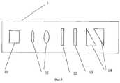
Сущность заявляемой системы открытой оптической связи поясняется примером ее реализации и чертежами. На фиг.1 схематично представлен общий вид системы с предпочтительным вариантом реализации базовой станции; на фиг.2 схематично показан поперечный разрез объектива в частном случае реализации - в виде концентрических слоев сферической формы; на фиг.3 представлена принципиальная схема предпочтительного варианта реализации устройства формирования оптического пучка, которым снабжены излучатели базовой станции и могут быть снабжены излучатели абонентских станций; на фиг.4 схематично показано устройство для регистрации угловых рассогласований. The essence of the claimed system of open optical communication is illustrated by an example of its implementation and drawings. Figure 1 schematically shows a General view of a system with a preferred embodiment of a base station; figure 2 schematically shows a transverse section of the lens in the particular case of implementation in the form of concentric layers of a spherical shape; Fig. 3 is a schematic diagram of a preferred embodiment of an optical beam forming apparatus with which base station emitters are provided and subscriber station emitters can be provided; figure 4 schematically shows a device for recording angular mismatches.
Система открытой оптической связи содержит базовую приемопередающую станцию 1 и несколько абонентских приемопередающих станций 2. Передающая станция содержит широкоугольный объектив 3, выполненный в виде одной линзы, выполняющий роль оптической антенны, который в частных случаях может быть выполнен в виде однородного или многослойного шара. Объектив закреплен в оправе 4, жестко закрепленной на основании станции (на чертеже не показано). На основании станции установлены несколько блоков 5, каждый из которых представляет собой объединенный в общем корпусе излучатель и устройство формирования оптического пучка. С оправой, непосредственно или через промежуточные элементы, жестко соединен датчик местной вертикали 6, который выбирается из числа известных (например, это может быть электропроводящий маятник, свободно колеблющийся в жидкой электропроводящей среде, размещенной в корпусе, на стенках которого закреплены контакты). Датчик соединен с блоком управления устройства стабилизации базовой станции (на чертеже не показано), которое может быть выбрано из числа известных. Кроме того, с основанием жестко соединены устройства привода 7, обеспечивающие угловое перемещение блоков 5 относительно него. С объективом оптически связаны фотодетекторы 8, которые в частных случаях могут быть снабжены световодами 9 для транспортировки оптического излучения, собранного объективом, к фотодетектору. В частных случаях эти световоды могут быть выполнены усиливающими. An open optical communication system includes a
Абонентские станции, так же как и базовая, могут быть снабжены аналогичными датчиком вертикали, устройствами формирования оптических пучков, устройствами регистрации углового рассогласования и т.п. На чертежах они не показаны, поскольку конструктивно аналогичны используемым на базовой станции. Кроме этого, абонентские станции снабжаются оптическими системами, обеспечивающими концентрацию излучения на их фотодетекторах (т.е. приемными оптическими системами), которые выбираются из числа известных. The subscriber stations, as well as the base station, can be equipped with similar vertical sensors, optical beam forming devices, angular mismatch recording devices, etc. They are not shown in the drawings, since they are structurally similar to those used at the base station. In addition, subscriber stations are equipped with optical systems that provide a concentration of radiation at their photodetectors (i.e., receiving optical systems), which are selected from among the known.
В блоке 5 устанавливается оптический излучатель (например, полупроводниковый лазер) и устройство формирования оптического пучка, которое в самом общем виде может быть выполнено в виде по крайней мере одного фокусирующего элемента или в предпочтительном варианте в виде телескопа 11 или аналогичной формирующей оптической системы и дополнено в частных случаях светофильтром 12, ослабителем 13 и парой оптических клиньев 14. In
Линзы телескопа 11 установлены с возможностью их трехкоординатного перемещения относительно излучателя и друг друга (или трехкоординатного перемещения излучателя относительно линз), а клинья - с возможностью вращения относительно оси оптического пучка. The lenses of the
Устройство регистрации угловых рассогласований содержит светоделитель 15, который может быть выполнен в виде полупрозрачной пластины или светоделительного кубика. Светоделитель устанавливается между элементами системы связи, угловое рассогласование которых между собой следует устранить, например, между устройством формирования оптического пучка базовой станции, размещенным в блоке 5 и приемной оптической системой абонентской станции 2. На пути отраженных от светоделителя световых пучков размещены с одной стороны ретрорефлектор 16 и фокусирующее устройство 17 - с другой. В фокальной области фокусирующего устройства размещают устройство 18 регистрации пространственного распределения интенсивности света, выполненное в виде фоточувствительного элемента, например в виде ПЗС-матрицы. The device for recording angular mismatches contains a
При этом устройство регистрации угловых рассогласований может быть выполнено стационарным, а может быть и переносным. Последний вариант представляется более дешевым, поскольку одно устройство может быть использовано при юстировке системы связи перед запуском и при проверке или при устранении рассогласований в процессе эксплуатации. В этом случае на станциях предусматриваются соответствующие установочные гнезда. In this case, the device for recording angular mismatches can be made stationary, or can be portable. The latter option seems to be cheaper, since one device can be used when adjusting the communication system before start-up and when checking or resolving inconsistencies during operation. In this case, the corresponding mounting sockets are provided at the stations.
Система оптической связи функционирует следующим образом. The optical communication system operates as follows.
Перед запуском системы оптической связи осуществляют юстировку приемопередающих устройств базовой станции 1 относительно абонентских станций 2 и каждой абонентской станции 2 относительно базовой станции 1. Для этого устройство регистрации угловых рассогласований должно быть размещено на базовой станции так, чтобы светоделитель 15 находился на пути прохождения света от устройства 5 формирования оптического пучка к приемной оптической системе абонентской станции 2. Устройство регистрации угловых рассогласований ориентируют так, чтобы изображение приемной оптической системы абонентской станции 2, формируемое фокусирующим устройством 17, оказалось на устройстве 18 регистрации пространственного распределения интенсивности света, которое и позволяет зарегистрировать это изображение, поскольку изображение физически представляет собой определенное пространственное распределение интенсивности света. Часть пучка от излучателя устройства 5 ответвляется светоделителем 15 на ретрорефлектор 16 (например, триппельпризма), который разворачивает световые лучи на 180o и направляет их на фокусирующее устройство 17. Это устройство формирует изображение дальней зоны пучка на элементе 18. Устройство 5 формирования оптического пучка ориентируют так, чтобы изображение пучка совместилось на устройстве 18 с изображением приемного устройства абонентской станции 2.Before starting the optical communication system, the transceivers of the
Таким образом, на устройстве 18 одновременно засвечиваются два пятна. Одно из них несет информацию о диаграмме направленности пучка базовой станции, а второе - о положении абонента. Совпадения этих пятен, фиксируемые по сигналам от устройства регистрации, соответствуют точному наведению пучка. Для обеспечения этого совпадения грубая юстировка осуществляется с помощью привода 7, обеспечивающих угловое перемещение блока 5 относительно основания станции, а более точная - путем поворота клиньев 14. Thus, on the
После этого устройство регистрации угловых рассогласований перемещают так, чтобы светоделитель был размещен на базовой станции между устройством формирования оптического пучка абонентской станции 2 и центром объектива 3 базовой станции 1 и путем перемещения приемника (фотодетектора 8 или конца световода 9, если он используется) добиваются совмещения изображения приемника на устройстве 18 с изображением выходной апертуры устройства формирования оптического пучка абонентской станции 2 по процедуре, описанной выше. After that, the device for recording the angular mismatches is moved so that the beam splitter is placed on the base station between the optical beam-forming device of the
Таким же путем осуществляют юстировку на абонентской станции, добиваясь соответственно углового согласования между устройством формирования пучка этой станции и приемным устройством базовой станции и между фотодетектором абонентской станции и устройством формирования пучка базовой станции. In the same way, alignment is carried out at the subscriber station, achieving, respectively, angular coordination between the beam-forming device of this station and the receiving device of the base station and between the photodetector of the subscriber station and the beam-forming device of the base station.
Проведение указанных выше котировочных операций с устройствами формирования пучка и приемными устройствами как на базовой станции, так и на абонентской обеспечивает расположение согласовываемых объектов на одной линии визирования и совмещение осей их диаграмм направленности. Излучение от излучателя 10 базовой станции 1, модулированное информационным сигналом с помощью известных средств модуляции (на чертежах не показаны), проходит последовательно устройство формирования пучка 11, светофильтр 12, ослабитель 13 и котировочные клинья 14 и через открытое пространство попадает на приемное устройство абонентской станции 2, которое выполнено известным образом, где подвергается демодуляции. Carrying out the above quotation operations with beam forming devices and receiving devices both at the base station and at the subscriber station ensures the location of the coordinated objects on the same line of sight and the alignment of the axes of their radiation patterns. The radiation from the
Аналогичным образом осуществляется передача от абонентской станции на приемное устройство базовой станции. На пути световых пучков от станции к станции в частных случаях могут быть установлены оптические усилители известной конструкции с необходимым набором оптических элементов, обеспечивающих прохождение передаваемых пучков через эти усилители (на чертеже не показаны в силу известности). Similarly, the transmission from the subscriber station to the receiving device of the base station. On the way of light beams from station to station, in special cases, optical amplifiers of known design can be installed with the necessary set of optical elements that ensure transmission of transmitted beams through these amplifiers (not shown due to popularity).
Компактность системы в сочетании с большой шириной углового поля приемного устройства позволяет одной базовой станции одновременно осуществлять обслуживание многих (до нескольких десятков) абонентов при высокой скорости информационного потока для каждого абонента (не менее 600 Мбит/с). The compactness of the system, combined with the large width of the angular field of the receiving device, allows one base station to simultaneously serve many (up to several dozen) subscribers at a high information flow rate for each subscriber (at least 600 Mbps).
Claims (20)
Translated fromRussianPriority Applications (2)
| Application Number | Priority Date | Filing Date | Title |
|---|---|---|---|
| RU2001122893/09ARU2212763C2 (en) | 2001-08-16 | 2001-08-16 | Open optical communication system |
| US09/983,227US7079774B2 (en) | 2001-08-16 | 2001-10-23 | Free-space optical communication system |
Applications Claiming Priority (1)
| Application Number | Priority Date | Filing Date | Title |
|---|---|---|---|
| RU2001122893/09ARU2212763C2 (en) | 2001-08-16 | 2001-08-16 | Open optical communication system |
Publications (2)
| Publication Number | Publication Date |
|---|---|
| RU2001122893A RU2001122893A (en) | 2003-06-27 |
| RU2212763C2true RU2212763C2 (en) | 2003-09-20 |
Family
ID=20252628
Family Applications (1)
| Application Number | Title | Priority Date | Filing Date |
|---|---|---|---|
| RU2001122893/09ARU2212763C2 (en) | 2001-08-16 | 2001-08-16 | Open optical communication system |
Country Status (2)
| Country | Link |
|---|---|
| US (1) | US7079774B2 (en) |
| RU (1) | RU2212763C2 (en) |
Cited By (5)
| Publication number | Priority date | Publication date | Assignee | Title |
|---|---|---|---|---|
| RU2388156C2 (en)* | 2004-09-23 | 2010-04-27 | Аирбус Дойчланд Гмбх | System for indirect optical communication in free space and high-speed broadband data transmission method |
| RU2580667C1 (en)* | 2015-02-27 | 2016-04-10 | Федеральное государственное бюджетное учреждение науки Институт проблем управления им. В.А. Трапезникова Российской академии наук | Method for laser wireless retro-reflector distributed optical switching and system therefor |
| RU2617207C1 (en)* | 2016-02-24 | 2017-04-24 | Ольга Олеговна Матросова | Method of subscriber access to data network |
| RU2685573C1 (en)* | 2018-07-04 | 2019-04-22 | АКЦИОНЕРНОЕ ОБЩЕСТВО "Научно-исследовательский институт оптико-электронного приборостроения" (АО "НИИ ОЭП") | Method of focusing optical radiation on object |
| RU2687989C2 (en)* | 2017-11-16 | 2019-05-17 | Общество с ограниченной ответственностью НаноРельеф Дисплей | Optical communication system |
Families Citing this family (24)
| Publication number | Priority date | Publication date | Assignee | Title |
|---|---|---|---|---|
| RU2219666C1 (en) | 2002-06-05 | 2003-12-20 | Общество с ограниченной ответственностью "Подсолнечник Технологии" | Light beam generating device |
| US20080138077A1 (en)* | 2004-10-26 | 2008-06-12 | Stephen Stretton | Diverging Beam Optical Communication System |
| US7606496B1 (en)* | 2005-06-02 | 2009-10-20 | Rockwell Collins, Inc. | Communications and position location system and method |
| US7646986B2 (en)* | 2006-04-27 | 2010-01-12 | Panasonic Corporation | Optical receiving device and optical receiving method |
| US8301032B2 (en)* | 2008-02-12 | 2012-10-30 | Arun Kumar Majumdar | Wide field-of-view amplified fiber-retro for secure high data rate communications and remote data transfer |
| NO20100377A1 (en)* | 2010-03-16 | 2011-09-19 | Polewall As | Method for pointing an optical receiver at a light source and apparatus for performing the method |
| US8666254B2 (en) | 2011-04-26 | 2014-03-04 | The Boeing Company | System and method of wireless optical communication |
| US9245443B2 (en) | 2013-02-21 | 2016-01-26 | The Boeing Company | Passenger services system for an aircraft |
| US10411812B1 (en)* | 2013-03-15 | 2019-09-10 | Forrest Rose | Optical interconnect computing module tolerant to changes in position and orientation |
| US9800332B2 (en)* | 2013-12-27 | 2017-10-24 | Space Photonics, Inc. | Acquisition, tracking, and pointing apparatus for free space optical communications with moving focal plane array |
| US9723386B1 (en)* | 2014-05-05 | 2017-08-01 | Google Inc. | Communication device |
| EP3189602A4 (en)* | 2014-09-04 | 2018-05-02 | Nokia Technology Oy | Free space communication |
| PE20180038A1 (en)* | 2015-05-21 | 2018-01-09 | Glaxosmithkline Ip Dev Ltd | TOPIC PHARMACEUTICAL COMPOSITIONS |
| US9747503B2 (en) | 2015-12-30 | 2017-08-29 | Surefire Llc | Optical narrowcasting augmented reality |
| EP3552325A4 (en) | 2016-12-06 | 2020-07-29 | LensVector Inc. | Liquid crystal beam control |
| US10277316B1 (en) | 2017-05-01 | 2019-04-30 | The United States Of America As Represented By The Secretary Of The Air Force | Free space optical headset |
| US9917652B1 (en) | 2017-06-06 | 2018-03-13 | Surefire Llc | Adaptive communications focal plane array |
| CN107634795B (en)* | 2017-10-20 | 2023-10-20 | 兰州理工大学 | Optical antenna of free space optical communication system and automatic alignment method thereof |
| US10250948B1 (en) | 2018-01-05 | 2019-04-02 | Aron Surefire, Llc | Social media with optical narrowcasting |
| US10473439B2 (en) | 2018-01-05 | 2019-11-12 | Aron Surefire, Llc | Gaming systems and methods using optical narrowcasting |
| US10236986B1 (en) | 2018-01-05 | 2019-03-19 | Aron Surefire, Llc | Systems and methods for tiling free space optical transmissions |
| WO2021069368A1 (en)* | 2019-10-09 | 2021-04-15 | Signify Holding B.V. | Optical wireless communication system and device |
| CN112165356B (en)* | 2020-09-29 | 2022-08-02 | 唐山德文电子商务有限公司 | Base station self-adaptive beam forming system and method based on optical communication |
| US12418342B2 (en) | 2021-04-13 | 2025-09-16 | Signify Holding B.V. | Optical detector |
Citations (4)
| Publication number | Priority date | Publication date | Assignee | Title |
|---|---|---|---|---|
| GB2180116A (en)* | 1985-08-29 | 1987-03-18 | Johnson Service Co | Data telemetry system using diffused infrared light |
| RU2138912C1 (en)* | 1994-09-03 | 1999-09-27 | Интернэшнл Бизнес Машинз Корпорейшн | Optical transmitting and receiving assembly for wireless data transmission |
| RU2172557C2 (en)* | 1996-08-09 | 2001-08-20 | Моторола, Инк. | Communication device |
| RU2174741C1 (en)* | 2000-12-19 | 2001-10-10 | Прохоров Дмитрий Владимирович | Optical air communication device |
Family Cites Families (15)
| Publication number | Priority date | Publication date | Assignee | Title |
|---|---|---|---|---|
| US3713163A (en)* | 1971-11-22 | 1973-01-23 | Nasa | Plural beam antenna |
| DE3328335C2 (en)* | 1983-08-05 | 1987-01-22 | Messerschmitt-Bölkow-Blohm GmbH, 8012 Ottobrunn | Remote data monitoring system |
| US5062150A (en)* | 1989-01-23 | 1991-10-29 | Massachusetts Institute Of Technology | Fiber-based free-space optical system |
| US4960315A (en)* | 1989-05-19 | 1990-10-02 | At&T Bell Laboratories | Atmosphric optical communication link |
| US5047776A (en)* | 1990-06-27 | 1991-09-10 | Hughes Aircraft Company | Multibeam optical and electromagnetic hemispherical/spherical sensor |
| US5887090A (en)* | 1995-06-30 | 1999-03-23 | Yissum Research Development Company Of The Hebrew University Of Jerusalem | Optical network |
| JP3859335B2 (en)* | 1996-12-17 | 2006-12-20 | Nec東芝スペースシステム株式会社 | Optical communication apparatus and optical communication system |
| GB9903142D0 (en) | 1999-02-11 | 1999-04-07 | Scient Generics Ltd | Free space optical communication system |
| US5909296A (en)* | 1997-04-04 | 1999-06-01 | The United States Of America As Represented By The Secretary Of The Air Force | Effective wide angle beam steering using spherical laser diode arrays |
| US6031648A (en)* | 1997-05-01 | 2000-02-29 | At&T Corp. | Automatic gain control for free-space optical telecommunications links |
| KR20010079835A (en)* | 1998-09-16 | 2001-08-22 | 추후 | Wireless optical communications without electronics |
| US6347001B1 (en)* | 1998-11-03 | 2002-02-12 | Trex Communications Corporation | Free-space laser communication system having six axes of movement |
| US6650451B1 (en)* | 1999-01-19 | 2003-11-18 | Lucent Technologies Inc. | Free space optical broadband access system |
| US6795655B1 (en)* | 2000-10-09 | 2004-09-21 | Meklyn Enterprises Limited | Free-space optical communication system with spatial multiplexing |
| US20020171896A1 (en)* | 2001-05-21 | 2002-11-21 | Lightpointe Communications, Inc. | Free-space optical communication system employing wavelength conversion |
- 2001
- 2001-08-16RURU2001122893/09Apatent/RU2212763C2/ennot_activeIP Right Cessation
- 2001-10-23USUS09/983,227patent/US7079774B2/ennot_activeExpired - Lifetime
Patent Citations (4)
| Publication number | Priority date | Publication date | Assignee | Title |
|---|---|---|---|---|
| GB2180116A (en)* | 1985-08-29 | 1987-03-18 | Johnson Service Co | Data telemetry system using diffused infrared light |
| RU2138912C1 (en)* | 1994-09-03 | 1999-09-27 | Интернэшнл Бизнес Машинз Корпорейшн | Optical transmitting and receiving assembly for wireless data transmission |
| RU2172557C2 (en)* | 1996-08-09 | 2001-08-20 | Моторола, Инк. | Communication device |
| RU2174741C1 (en)* | 2000-12-19 | 2001-10-10 | Прохоров Дмитрий Владимирович | Optical air communication device |
Non-Patent Citations (1)
| Title |
|---|
| ПРАТТ В.К. Лазерные системы связи. - М.: Связь, 1972, с.44. КЕРР ТИТТЕРТОН и др. Оптическая связь через атмосферу. ТИИЭР, 1970, 58, №10, с.318.* |
Cited By (5)
| Publication number | Priority date | Publication date | Assignee | Title |
|---|---|---|---|---|
| RU2388156C2 (en)* | 2004-09-23 | 2010-04-27 | Аирбус Дойчланд Гмбх | System for indirect optical communication in free space and high-speed broadband data transmission method |
| RU2580667C1 (en)* | 2015-02-27 | 2016-04-10 | Федеральное государственное бюджетное учреждение науки Институт проблем управления им. В.А. Трапезникова Российской академии наук | Method for laser wireless retro-reflector distributed optical switching and system therefor |
| RU2617207C1 (en)* | 2016-02-24 | 2017-04-24 | Ольга Олеговна Матросова | Method of subscriber access to data network |
| RU2687989C2 (en)* | 2017-11-16 | 2019-05-17 | Общество с ограниченной ответственностью НаноРельеф Дисплей | Optical communication system |
| RU2685573C1 (en)* | 2018-07-04 | 2019-04-22 | АКЦИОНЕРНОЕ ОБЩЕСТВО "Научно-исследовательский институт оптико-электронного приборостроения" (АО "НИИ ОЭП") | Method of focusing optical radiation on object |
Also Published As
| Publication number | Publication date |
|---|---|
| US7079774B2 (en) | 2006-07-18 |
| US20030035182A1 (en) | 2003-02-20 |
Similar Documents
| Publication | Publication Date | Title |
|---|---|---|
| RU2212763C2 (en) | Open optical communication system | |
| US6829439B1 (en) | Optical communication device | |
| US4651343A (en) | Piezoelectric apparatus for positioning optical fibers | |
| US5777768A (en) | Multiple transmitter laser link | |
| JP4753444B2 (en) | Communication transceiver architecture | |
| US20040042798A1 (en) | Optical transceiver with a dual-axis tilt mirror for pointing and tracking free space communication signals | |
| US10180543B2 (en) | Optical path control system and optical module | |
| RU2001122893A (en) | Open optical communication system | |
| US12147086B2 (en) | Imaging-based transmitter for free-space optical communications | |
| US11515941B2 (en) | Free space optical communication terminal with dispersive optical component | |
| US20020081060A1 (en) | MEMS based over-the-air optical data transmission system | |
| RU2174741C1 (en) | Optical air communication device | |
| CN108873181A (en) | light path control system and optical module | |
| JP4701454B2 (en) | Spatial optical communication method and spatial optical communication apparatus | |
| CN217766922U (en) | Optical communication device | |
| LV14146B (en) | Optisk &amacr; &Emacr; s Air Optical Communication &Imacr; | |
| JP3206993B2 (en) | Bidirectional optical space transmission equipment | |
| EP1162770A2 (en) | Free space optical communication device | |
| RU2264691C2 (en) | Open optical communication system | |
| Watanabe et al. | Robotic alignment technique of search control for laser beam communication | |
| JP2858488B2 (en) | Light source | |
| US7760976B1 (en) | Method and system for pointing a laser beam | |
| RU2272358C1 (en) | Two-way optical communication device | |
| RU2842479C1 (en) | Atmospheric optical transmission system transceiver device | |
| RU41397U1 (en) | OPEN OPTICAL COMMUNICATION TERMINAL |
Legal Events
| Date | Code | Title | Description |
|---|---|---|---|
| PC4A | Invention patent assignment | Effective date:20070131 | |
| MM4A | The patent is invalid due to non-payment of fees | Effective date:20130817 |