RU2210051C1 - Kudriakov's shooting trainer - Google Patents
Kudriakov's shooting trainerDownload PDFInfo
- Publication number
- RU2210051C1 RU2210051C1RU2002128184ARU2002128184ARU2210051C1RU 2210051 C1RU2210051 C1RU 2210051C1RU 2002128184 ARU2002128184 ARU 2002128184ARU 2002128184 ARU2002128184 ARU 2002128184ARU 2210051 C1RU2210051 C1RU 2210051C1
- Authority
- RU
- Russia
- Prior art keywords
- target
- channel
- signal
- amplitude
- radiation
- Prior art date
Links
- 230000005855radiationEffects0.000claimsabstractdescription24
- 230000005236sound signalEffects0.000claimsabstractdescription15
- 238000010304firingMethods0.000claimsdescription23
- 230000003287optical effectEffects0.000claimsdescription15
- 230000005693optoelectronicsEffects0.000abstractdescription16
- 238000000034methodMethods0.000abstractdescription9
- 230000007547defectEffects0.000abstractdescription2
- 238000012544monitoring processMethods0.000abstract1
- 239000000126substanceSubstances0.000abstract1
- 230000009466transformationEffects0.000abstract1
- 238000004364calculation methodMethods0.000description6
- 238000010586diagramMethods0.000description4
- 238000004519manufacturing processMethods0.000description4
- 230000000007visual effectEffects0.000description4
- 230000007423decreaseEffects0.000description2
- 210000000056organAnatomy0.000description2
- 230000035945sensitivityEffects0.000description2
- NIOPZPCMRQGZCE-WEVVVXLNSA-N2,4-dinitro-6-(octan-2-yl)phenyl (E)-but-2-enoateChemical compoundCCCCCCC(C)C1=CC([N+]([O-])=O)=CC([N+]([O-])=O)=C1OC(=O)\C=C\CNIOPZPCMRQGZCE-WEVVVXLNSA-N0.000description1
- 230000003321amplificationEffects0.000description1
- 239000000969carrierSubstances0.000description1
- 238000006243chemical reactionMethods0.000description1
- 230000007717exclusionEffects0.000description1
- 238000003199nucleic acid amplification methodMethods0.000description1
- 230000001902propagating effectEffects0.000description1
- 238000000926separation methodMethods0.000description1
- 238000004088simulationMethods0.000description1
- 230000008685targetingEffects0.000description1
- 230000007704transitionEffects0.000description1
Images


Landscapes
- Aiming, Guidance, Guns With A Light Source, Armor, Camouflage, And Targets (AREA)
Abstract
Description
Translated fromRussianИзобретение относится к техническим средствам обучения стрельбе из стрелкового оружия без применения боевых патронов и может быть использовано для обучения стрельбе из различных видов стрелкового оружия в условиях закрытых помещений и в полевых условиях. The invention relates to technical means of teaching shooting from small arms without the use of live ammunition and can be used to teach shooting from various types of small arms in closed rooms and in the field.
Известен тренажер по патенту US 6269730, F 41 G 3/26, 07.08.2001, в котором точность прицеливания, помимо визуального контроля, определяют по звуковым сигналам. Known simulator according to patent US 6269730, F 41 G 3/26, 08/07/2001, in which the accuracy of aiming, in addition to visual control, is determined by sound signals.
Недостатком известного тренажера является то, что звуковой контроль используется лишь для фиксирования факта точного прицеливания. A disadvantage of the known simulator is that sound control is used only to record the fact of accurate aiming.
Наиболее близким аналогом по совокупности существенных признаков является тренажер по патенту RU 2060437, F 41 G 3/26, 20.05.1996, который содержит оптический источник излучения, установленный на мишени, приемник излучения, установленный на оружии, блок обработки и регистрации результатов стрельбы, блок звукового контроля, выполненный с возможностью подачи звуковых сигналов стрелку в процессе наведения оружия. The closest analogue in terms of essential features is the simulator according to patent RU 2060437, F 41 G 3/26, 05.20.1996, which contains an optical radiation source mounted on a target, a radiation receiver mounted on a weapon, a unit for processing and recording the results of firing, a unit sound control, made with the possibility of sound signals to the arrow in the process of pointing weapons.
Недостатком прототипа является низкая эффективность звукового контроля при скоростной стрельбе, стрельбе по подвижным и появляющимся целям, т.к. не обеспечивает стреляющего объективной информацией о положении оружия относительно цели в процессе прицеливания. The disadvantage of the prototype is the low efficiency of sound control during high-speed shooting, shooting at moving and emerging targets, because It does not provide the shooter with objective information about the position of the weapon relative to the target during the aiming process.
Задачей изобретения является повышение качества и сокращение сроков обучения различным видам стрельбы. The objective of the invention is to improve the quality and reduce the training time for various types of shooting.
Технический результат заключается в повышении достоверности информации о положении оружия относительно цели в процессе прицеливания и повышение точности стрельбы в условиях недостаточной видимости или при наличии у стрелка дефектов зрения. The technical result consists in increasing the reliability of information about the position of the weapon relative to the target during the aiming process and increasing the accuracy of shooting in conditions of insufficient visibility or if the shooter has visual defects.
Указанный технический результат достигается тем, что стрелковый тренажер содержит мишень, в центре которой установлен оптический источник излучений и оптико-электронный приемник излучений, установленный на стрелковом оружии и связанный с блоками обработки принятого сигнала, звукового контроля и регистрации результатов стрельбы. В упомянутом тренажере оптико-электронный приемник излучений выполнен двухканальным, при этом один канал, с ненаправленным приемом излучений, выполнен с возможностью формирования на своем выходе опорного сигнала, амплитуда которого остается постоянной в процессе смещения линии прицеливания в границах внешнего круга мишени, а другой канал, с направленным приемом излучений, выполнен с возможностью формирования на своем выходе информационного сигнала, амплитуда которого меняется от минимума, при совпадении линии прицеливания с границей внешнего круга мишени, до максимума, равного амплитуде опорного сигнала, при совпадении линии прицеливания с центром мишени, причем блок звукового контроля выполнен с возможностью приема упомянутых сигналов и преобразования их в соответствующие звуковые сигналы. The specified technical result is achieved in that the shooting simulator contains a target, in the center of which there is an optical radiation source and an optoelectronic radiation receiver mounted on small arms and connected to the received signal processing, sound control and firing registration units. In the said simulator, the optoelectronic radiation receiver is made two-channel, while one channel, with non-directional radiation reception, is configured to generate a reference signal at its output, the amplitude of which remains constant during the shift of the aiming line within the boundaries of the outer circle of the target, and the other channel with directed radiation reception, it is made with the possibility of generating an information signal at its output, the amplitude of which changes from a minimum, when the aiming line coincides with the border the outer circle of the target, to a maximum of the amplitude of the reference signal at the coincidence of the center line of sight with the target, wherein the sound control unit is configured to receive said signals and converting them into corresponding sound signals.
Так как опорный и информационный сигналы формируются от единого для обоих каналов сигнала, что, в свою очередь, обеспечивает независимость относительных значений обоих сигналов от уровня входного сигнала, поступающего от мишенного устройства, то относительная точность наведения оружия на цель не зависит от дистанции стрельбы. Это позволяет осуществить жесткую привязку текущего значения информационного сигнала к габариту кругов мишени, по которой ведется стрельба, и оперативно передать стрелку информацию в виде звуковых сигналов. Since the reference and information signals are generated from a signal that is common to both channels, which, in turn, ensures that the relative values of both signals are independent of the level of the input signal coming from the target device, the relative accuracy of pointing the weapon at the target does not depend on the firing distance. This allows you to tightly link the current value of the information signal to the size of the circles of the target, which is firing, and quickly transmit information to the arrow in the form of sound signals.
В частных случаях реализации канал с ненаправленным приемом излучений выполнен в виде расположенной на входе собирающей линзы, в главном фокусе которой установлена диафрагма с калиброванным отверстием и фотоэлемент, а канал с направленным приемом излучений выполнен в виде оптического фильтра, установленного на входе, и собирающей линзы, в главном фокусе которой установлен фотоэлемент. In particular cases of implementation, the channel with non-directional reception of radiation is made in the form of a collecting lens located at the input, in the main focus of which there is a diaphragm with a calibrated hole and a photocell, and the channel with directed radiation reception is made in the form of an optical filter installed at the input and collecting lenses, in the main focus of which a photocell is installed.
Кроме того, звуковой сигнал, преобразованный из опорного сигнала, имеет постоянную тональность, а звуковой сигнал, преобразованный из информационного сигнала, - переменную. In addition, an audio signal converted from a reference signal has a constant tonality, and an audio signal converted from an information signal has a variable.
Изобретение иллюстрируется чертежами, где:
на фиг.1 - изображена структурная схема тренажера;
на фиг.2 - график амплитуды опорного сигнала;
на фиг.3 - график информационного сигнала;
на фиг.4 - оптическая схема канала с пространственным излучением;
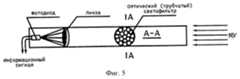
на фиг.5 - оптическая схема канала с направленным излучением;
на фиг.6 - конструкция оптико-электронной насадки.The invention is illustrated by drawings, where:
figure 1 - shows a structural diagram of a simulator;
figure 2 is a graph of the amplitude of the reference signal;
figure 3 is a graph of an information signal;
figure 4 is an optical diagram of a channel with spatial radiation;
figure 5 is an optical diagram of a channel with directional radiation;
figure 6 - design of the optoelectronic nozzle.
Стрелковый тренажер содержит мишенное устройство (МУ), которое выполнено в виде стандартной съемной мишени 1, в центре которой установлен оптический излучатель - источник лучистой энергии. The shooting simulator contains a target device (MU), which is made in the form of a standard
Им может быть, например, диод инфракрасного (ИК) излучения (АЛ107), работающий от формирователя излучаемого диодом сигнала 2. Подводимый к диоду сигнал модулирован по амплитуде. It can be, for example, an infrared (IR) radiation diode (AL107) operating from a shaper of a signal emitted by a diode 2. The signal supplied to the diode is modulated in amplitude.
Как вариант, в качестве источника лучистой энергии мишенного устройства в центре стандартной съемной мишени 1 вместо оптического излучателя может быть установлен оптический отражатель. В этом случае оптический излучатель и формирователь излучаемого сигнала устанавливаются на оружии стрелка. Alternatively, an optical reflector may be installed in the center of a standard
Приемником излучаемого (отраженного) мишенным устройством сигнала является оптико-электронная насадка 3, которая устанавливается на стрелковом оружии, предназначенном для ведения имитационной стрельбы, в отличие от известных имитаторов, где оптико-электронная насадка вмонтирована непосредственно в само оружие. The receiver of the signal emitted (reflected) by the target device is an optoelectronic nozzle 3, which is mounted on a small arms designed for firing simulations, in contrast to the well-known imitators, where the optoelectronic nozzle is mounted directly into the weapon itself.
Оптико-электронная насадка 3 выполнена двухканальной. На выходе одного канала формируется опорный сигнал (Uoпoрн.), а на выходе другого - информационный (Uинф.).Optoelectronic nozzle 3 is a two-channel. At the output of one channel, a reference signal is formed (Ureference ), and at the output of the other, an information signal (Uinf. ).
Опорный сигнал имеет постоянную амплитуду выходного напряжения при наведении стрелкового оружия на цель в процессе грубой и тонкой наводки, т.е. его амплитуда остается постоянной в процессе смещения линии прицеливания в границах внешнего круга мишени (фиг.2). The reference signal has a constant amplitude of the output voltage when pointing small arms at the target during coarse and fine aiming, i.e. its amplitude remains constant in the process of shifting the line of sight within the outer circle of the target (figure 2).
Амплитуда информационного сигнала на выходе другого канала переменная и зависит от точности наведения стрелкового оружия на цель, т.е. амплитуда информационного сигнала меняется от минимума, при совпадении линии прицеливания с границей внешнего круга мишени, до максимума, равного амплитуде опорного сигнала, при совпадении линии прицеливания с центром мишени (фиг.3). The amplitude of the information signal at the output of another channel is variable and depends on the accuracy of pointing the small arms at the target, i.e. the amplitude of the information signal varies from the minimum, when the line of sight coincides with the boundary of the outer circle of the target, to a maximum equal to the amplitude of the reference signal, when the line of sight coincides with the center of the target (figure 3).
Оптико-электронная система, формирующая опорный сигнал (фиг.4), состоит из установленной на входе собирающей линзы, в главном фокусе которой установлена диафрагма с калиброванным отверстием и фотоэлемент. Постоянство амплитуды опорного сигнала обеспечивается тем, что его оптико-электронная система рассчитана на прием излучений, поступающих от мишенного устройства в границах внешнего габаритного круга мишени. The optoelectronic system that forms the reference signal (Fig. 4) consists of a collecting lens installed at the input, in the main focus of which there is a diaphragm with a calibrated hole and a photocell. The constancy of the amplitude of the reference signal is ensured by the fact that its optoelectronic system is designed to receive radiation coming from the target device within the boundaries of the outer dimensional circle of the target.
При выходе точки прицеливания за пределы внешнего габаритного круга мишени амплитуда выходного сигнала уменьшается до нулевого значения. When the aiming point goes beyond the external dimensional circle of the target, the amplitude of the output signal decreases to zero.
Оптико-электронная система формирования информационного сигнала (фиг.5) состоит из оптического остронаправленного линейчатого фильтра, установленного на входе собирающей линзы, в главном фокусе которой установлен фотоэлемент. The optoelectronic system for generating an information signal (Fig. 5) consists of an optically sharpened line filter installed at the input of a collecting lens, in the main focus of which a photocell is installed.
Один из вариантов конструкции оптико-электронной насадки 3 представлен на фиг.6. One of the design options of the optoelectronic nozzle 3 is presented in Fig.6.
Расчет конструктивных элементов оптико-электронной насадки производится по следующей схеме. The calculation of the structural elements of the optoelectronic nozzle is performed according to the following scheme.
За исходные данные принимаются:
- дистанция стрельбы (для короткоствольного оружия она составляет 25 м, для длинноствольного -100 м;
- диаметр внешнего круга мишени при стрельбе на дистанцию 25 м и 100 м (при стрельбе из пистолета и автомата мишень М4 с кругами. Диаметр внешнего круга составляет 70 см);
- ширина огневого рубежа, откуда ведется стрельба (при групповом обучении для размещения 5-7 стрелковых мест необходим огневой рубеж шириной около 5 м); излучаемая мощность источника лучистой энергии, установленного на мишенном устройстве (в ТСК-1 в качестве излучателя применен диод АЛ107Б, излучаемая мощность которого составляет порядка 10 мВт).For the initial data are taken:
- firing distance (for short-barrel weapons it is 25 m, for long-barrel -100 m;
- the diameter of the outer circle of the target when firing at a distance of 25 m and 100 m (when firing with a pistol and machine gun target M4 with circles. The diameter of the outer circle is 70 cm);
- the width of the firing line from where the firing is being carried out (in group training, a firing line of about 5 m wide is needed to accommodate 5-7 shooting places); radiated power of a radiant energy source installed on the target device (in ТСК-1, the AL107B diode is used as a radiator, the radiated power of which is about 10 mW).
Произведем расчет для короткоствольного оружия (пистолет ПМ). We will calculate for short-barreled weapons (PM pistol).
1. Расчет приемника и формирователя опорного сигнала. Диаметр внешнего круга мишени М4 при стрельбе на 25 м составляет D1=70 см. Фокусное расстояние входной линзы примем равным 5 см, диаметр линзы -10 мм. 1. The calculation of the receiver and the driver of the reference signal. The diameter of the outer circle of the M4 target when shooting at 25 m is D1 = 70 cm. The focal length of the input lens is assumed to be 5 cm, the diameter of the lens is 10 mm.
Диаметр отверстия диафрагмы определим по формуле
2. Расчет приемника формирователя информационного канала
Расчет производится с учетом полученных выше данных по формирователю опорного сигнала.The diameter of the aperture is determined by the formula
2. Calculation of the receiver of the shaper information channel
The calculation is based on the above data on the reference signal shaper.
А) Расчет трубчатого светофильтра произведем для единичного элемента, представляющего собой трубку определенного диаметра и заданной длины. A) Calculation of the tubular filter will produce for a single element, which is a tube of a certain diameter and a given length.
Исходя из конструктивной и эксплуатационной целесообразности длину трубки примем равной 10 см, а необходимый внутренний диаметр определим по формуле:
D отверстия=(0,5 длины трубки • диаметр внешнего круга мишени)/дистанция стрельбы
Б) Принимая во внимание требование в отношении одинаковой чувствительности одного и другого каналов оптико-электронной насадки, произведем расчет количества трубок, обеспечивающих это требование.Based on the constructive and operational feasibility, we take the length of the tube equal to 10 cm, and the required internal diameter is determined by the formula:
D holes = (0.5 tube length • diameter of the outer circle of the target) / firing distance
B) Taking into account the requirement for the same sensitivity of one and the other channels of the optoelectronic nozzle, we will calculate the number of tubes providing this requirement.
Площадь входного светового отверстия со стороны линзы опорного канала составляет
Площадь входного отверстия единичного элемента светофильтра
Количество трубок в комплекте светофильтра составит
В) При 2-рядной укладке единичных элементов диаметр линзы информационного канала составит 17 мм с фокусным расстоянием в 2-5 см (как позволяет конструкция).The area of the light input hole from the lens side of the reference channel is
The area of the inlet of a single element of the filter
The number of tubes in the filter kit is
C) With a 2-row stacking of single elements, the diameter of the lens of the information channel will be 17 mm with a focal length of 2-5 cm (as the design allows).
Расчет конструктивных элементов оптико-электронной насадки к длинноствольному оружию производится аналогично. The calculation of the structural elements of the optoelectronic nozzle for long-barrel weapons is carried out similarly.
Тренажер работает следующим образом. The simulator works as follows.
На стрелковое оружие устанавливают оптико-электронную насадку 3 и производят юстировку ее оптической оси относительно оси прицельного приспособления указанного оружия до полного их совпадения. An optical-electronic nozzle 3 is mounted on the small arms and its optical axis is adjusted relative to the axis of the sights of the specified weapon until they coincide.
Так как излучатель мишенного устройства является источником лучистой энергии, то оптический фильтр оптико-электронной системы формирования информационного сигнала, установленный перед собирающей линзой, пропускает в полную силу только лучи, распространяющиеся параллельно его оптической оси. В связи с этим при наведении стрелкового оружия точно в центр мишени, когда оптический фильтр обладает наибольшей пропускной способностью, на выходе оптико-электронной системы формируется сигнал максимальной амплитуды, равный по абсолютной величине опорному сигналу. Since the emitter of the target device is a source of radiant energy, the optical filter of the optoelectronic system for generating the information signal installed in front of the collecting lens transmits in full force only the rays propagating parallel to its optical axis. In this regard, when aiming small arms exactly at the center of the target, when the optical filter has the highest throughput, a signal of maximum amplitude equal to the absolute value of the reference signal is formed at the output of the optoelectronic system.
При изменении направленности оружия по отношению к цели, а следовательно, и оптической оси фильтра амплитуда выходного сигнала уменьшается. Нулевое значение информационного сигнала свидетельствует о том, что линия прицеливания вышла за внешний габаритный круг мишени. With a change in the direction of the weapon with respect to the target, and hence the optical axis of the filter, the amplitude of the output signal decreases. The zero value of the information signal indicates that the line of sight has gone beyond the outer overall circle of the target.
Опорный и информационный сигналы раздельно поступают на вход контрольно регистрирующего устройства (фиг.1). The reference and information signals are separately fed to the input of the control recording device (Fig. 1).
Так как уровень обоих сигналов, поступающих с выхода приемника излучений мишенного устройства, очень мал, сигналы усиливаются, преобразуются в постоянный ток и далее поступают на блоки обработки контрольно регистрирующего устройства:
- на блок визуально-звукового контроля 7-19;
- на блок свето-цифровой отметки и регистрации результатов стрельбы 6;
- на блок разрешения прицельной стрельбы 5.Since the level of both signals coming from the output of the radiation receiver of the target device is very small, the signals are amplified, converted to direct current and then fed to the processing units of the control recording device:
- to the block of visual-sound control 7-19;
- to the block of light-digital marking and recording the results of firing 6;
- on the block of permission of aimed
При нажатии на спусковой крючок и производстве выстрела с контактной группы 20 (фиг. 1), непосредственно связанной со спусковым крючком оружия, подается сигнал на блок управления стрельбой 21, который управляет работой блока свето-цифровой отметки и регистрации результатов стрельбы 6 и имитатором звука выстрела 18. Электропитание тренажера осуществляется от блока 22 - встроенной в контрольно регистрирующее устройство (КРУ) аккумуляторной батареи. Предусматривается электропитание КРУ и от внешнего источника - сети переменного тока напряжением 220 В, 50 Гц. When you press the trigger and firing from the contact group 20 (Fig. 1), directly connected with the trigger of the weapon, a signal is sent to the firing control unit 21, which controls the operation of the light-digital marking unit and recording the results of firing 6 and the firing sound simulator 18. The power supply of the simulator is carried out from the unit 22 - built-in control battery recording device (KRU). The switchgear power supply is also provided from an external source - AC network voltage of 220 V, 50 Hz.
Органы слуха человека таковы, что они хорошо воспринимают и различают звуки по частоте (тону) звучания. Также легко различаются звуки с разным тембром звучания, даже если они одной и той же частоты. The human hearing organs are such that they perceive and distinguish sounds well by the frequency (tone) of the sound. Sounds with different timbres of sound are also easily distinguished, even if they are of the same frequency.
По-разному воспринимают органы слуха моно- и стереозвучание. Например, двухчастотный звук подается на головные телефоны для прослушивания в неразделенном по частоте виде или в разделенном - к одному наушнику поступает звук одной частоты, а к другому - другой частоты. Mono and stereo sound are perceived differently by the hearing organs. For example, dual-frequency sound is fed to the headphone for listening in an inseparable form of frequency or in a split form - one earphone receives sound of one frequency, and to another - of a different frequency.
В первом случае, неразделенные по частоте звуки маскируют друг друга, а во втором случае разделенные по частоте и наушникам звуки не влияют друг на друга и их различимость и громкость оказываются максимальными. In the first case, sounds not separated by frequency mask each other, and in the second case, sounds separated by frequency and headphones do not affect each other and their distinguishability and volume turn out to be maximum.
В связи с этим исключение из информационного звукового сигнала амплитудной составляющей и использование режима стереоприема повышает чувствительность приема звукового сигнала и соответственно повышает эффективность звукового контроля. In this regard, the exclusion of the amplitude component from the information sound signal and the use of the stereo mode increase the sensitivity of receiving the sound signal and, accordingly, increase the effectiveness of sound control.
Таким образом, при обучении технике любого вида стрельбы в полной мере используется объективность звукового контроля в сочетании с оперативностью передачи стрелку звуковой информации, что позволяет ему своевременно принимать меры по устранению допущенных ошибок в процессе изготовки, прицеливания и производства выстрела. Thus, when learning the technique of any type of shooting, the objectivity of sound control is fully used in conjunction with the speed of transmitting the arrow of sound information, which allows him to take timely measures to eliminate errors made during the manufacture, aiming and firing of a shot.
Носителями звуковой информации, передаваемой стрелку по каналу обратной связи в ходе изготовки, прицеливания и производства выстрела, являются следующие звуковые сигналы:
а) монотонный низкочастотный звук появляется в одном из наушников при готовности стрелка к открытию прицельного огня после завершения изготовки в начале проведения грубой наводки оружия на цель;
б) появление на фоне монотонного звучания низкой частоты сначала редких, а затем частых щелчков, переходящих в прерывистое звучание той же частоты, является сигналом завершения грубой наводки;
в) появление в другом наушнике сначала редких, а затем частых щелчков звука более высокой частоты, по сравнению с частотой звука, характерной для грубой наводки, обозначает границу тонкой наводки;
г) в процессе проведения стрелком тонкой наводки, заканчивающейся точным наведением оружия в цель, являются следующие сигналы:
- прекращение звучания в наушнике низкочастотного сигнала-спутника, обозначающего грубую наводку;
- переход редких щелчков в часто повторяющиеся на фоне тонального звучания высокой частоты;
- появление тонального монотонного звучания той же высокой частоты;
д) нажатие на спусковой крючок и производство выстрела осуществляются при монотонном и непрерывном звучании в одном наушнике высокочастотного тона;
е) появление в свободном от звучания наушнике звукового сигнала, имитирующего звук выстрела боевого оружия, является сигналом завершения выстрела.The carriers of the sound information transmitted to the shooter through the feedback channel during the manufacture, aiming and firing of the shot are the following sound signals:
a) a monotonous low-frequency sound appears in one of the headphones when the shooter is ready to open aimed fire after completion of manufacture at the beginning of a rough aiming of the weapon at the target;
b) the appearance, against the background of the monotonous sound of a low frequency, first of rare, and then frequent clicks, turning into an intermittent sound of the same frequency, is a signal for completion of rough aiming;
c) the appearance of rare and then frequent clicks of sound of a higher frequency in another earphone, in comparison with the sound frequency characteristic of coarse pickup, indicates the border of a fine pickup;
d) in the process of the shooter conducting a fine tip, ending with the precise aiming of the weapon at the target, the following signals are:
- cessation of sound in the headphone low-frequency satellite signal, indicating coarse pickup;
- the transition of rare clicks into those often repeated against the background of high-frequency tonal sound;
- the appearance of tonal monotonous sound of the same high frequency;
e) pulling the trigger and firing the shot are carried out with monotonous and continuous sounding in one earphone of a high-frequency tone;
e) the appearance in the earphone-free sound signal simulating the sound of a shot of a military weapon is a signal of completion of the shot.
Своевременный учет визуальной и звуковой информации, описанной в изложенных выше пунктах, обеспечивает повышение точности стрельбы из стрелкового оружия. Timely accounting of visual and audio information described in the paragraphs above provides improved accuracy of fire from small arms.
Канал звукового контроля, структурная схема которого представлена на фиг.1, осуществляет передачу информации следующим образом. The sound control channel, the structural diagram of which is presented in figure 1, transmits information as follows.
При обнаружении цели и проведении стрелком необходимой изготовки для открытия огня, когда оружие направлено в сторону цели (начало грубой наводки), с выхода усилителя 4 опорный сигнал поступает на вход блока разрешения прицельной стрельбы 5, при помощи которого (выход - а) включается в работу канал звукового контроля. When a target is detected and the shooter is in the necessary position to open fire, when the weapon is aimed toward the target (the beginning of a rough aim), from the output of amplifier 4, the reference signal is fed to the input of the target
Опорный и информационный сигналы после усиления и преобразования в положительную полярность поступают на вход дифференциального усилителя 7, причем информационный сигнал подводится к инвертируемому входу (-) упомянутого усилителя 7, а опорный сигнал через "регулятор точности наведения орудия в цель" 19 поступает на неинвертируемый вход (+). The reference and information signals, after amplification and conversion to positive polarity, are fed to the input of the differential amplifier 7, the information signal being supplied to the invertible input (-) of the mentioned amplifier 7, and the reference signal through the "accuracy of the targeting of the guns to the target" 19 signal is sent to the non-invertible input ( +).
При тренировке начинающих и малотренированных стрелков указанный регулятор 19 устанавливается в положение, когда информационный сигнал формируется в пределах габаритного круга мишени большого размера (габаритный круг 6-7), а для тренированных стрелков указанный регулятор устанавливается в положение, когда информационный сигнал формируется в пределах габаритного круга мишени меньшего размера (габаритный круг 8-9-10). When training beginners and low-trained shooters, the specified regulator 19 is set to the position when an information signal is generated within the overall circle of the large target (large circle 6-7), and for trained shooters, this regulator is set to the position when the information signal is formed within the overall circle smaller targets (clearance circle 8-9-10).
Усилитель работает в режиме ограничения усиливаемых сигналов. Следовательно, при равных или близких к этим значениям сигналах, поступающих на вход усилителя, на выходе его формируется разностный сигнал. The amplifier operates in the mode of limiting amplified signals. Therefore, at equal or close to these values of the signals supplied to the input of the amplifier, a difference signal is formed at its output.
В зависимости от уровней текущих значений опорного и информационного сигналов, поступающих на вход усилителя, на его выходе формируются при Δ Uопорн > Δ Uинф выходной сигнал положительной полярности, а при Δ Uопорн < Δ Uинф - отрицательной полярности. Разностный сигнал через разделительные диоды 8, 9 поступает на модуляторы 10, 12, где сигнал положительной полярности (опорный) модулируется тоном низкочастотного генератора, а сигнал отрицательной полярности (информационный) модулируется тоном высокочастотного генератора 11.Depending on the levels of the current values of the reference and information signals input to the amplifier input, an output signal of positive polarity is formed at Δ Ureference > Δ Uinf at Δ Ureference <Δ Uinf and negative polarity. The difference signal through the
Полученный таким образом тональный низкочастотный или высокочастотный сигнал раздельно поступает на вход усилителей мощности 14, 15, с выхода которых раздельно подается на стереотелефоны 16, 17 для осуществления стрелком звукового контроля. Thus obtained tonal low-frequency or high-frequency signal is separately fed to the input of power amplifiers 14, 15, the output of which is separately fed to stereo phones 16, 17 for sound control by the shooter.
При нажатии на спусковой крючок в момент производства имитационного выстрела на вход усилителя 15 низкочастотного сигнала подается сигнал от имитатора звука выстрела 18. When you press the trigger at the time of the firing shot at the input of the amplifier 15 of the low-frequency signal, the signal from the simulator of the sound of the shot 18.
Таким образом, на головные телефоны стрелка с момента завершения им изготовки в непрерывном и раздельном режимах подаются звуковые сигналы разной тональности, несущие информацию о точности наведения оружия в цель, что позволяет стрелку, не прибегая к общепринятому визуальному контролю, оперативно оценивать точность наведения оружия в цель в процессе прицеливания и производства выстрела независимо от вида стрельбы. Thus, from the moment the gunman completes production in continuous and separate modes, sound signals of different tonality are transmitted to the shooter's head phones, which carry information about the accuracy of pointing the weapon at the target, which allows the shooter to quickly evaluate the accuracy of pointing the weapon at the target without resorting to conventional visual control in the process of aiming and firing a shot, regardless of the type of fire.
Использование звукового контроля описанным выше образом позволяет обучать стрельбе из стрелкового оружия стрелков с плохим зрением. Using sound control in the manner described above allows you to teach small-sighted shooters to shoot from small arms.
Claims (3)
Translated fromRussianPriority Applications (1)
| Application Number | Priority Date | Filing Date | Title |
|---|---|---|---|
| RU2002128184ARU2210051C1 (en) | 2002-10-23 | 2002-10-23 | Kudriakov's shooting trainer |
Applications Claiming Priority (1)
| Application Number | Priority Date | Filing Date | Title |
|---|---|---|---|
| RU2002128184ARU2210051C1 (en) | 2002-10-23 | 2002-10-23 | Kudriakov's shooting trainer |
Publications (1)
| Publication Number | Publication Date |
|---|---|
| RU2210051C1true RU2210051C1 (en) | 2003-08-10 |
Family
ID=29246881
Family Applications (1)
| Application Number | Title | Priority Date | Filing Date |
|---|---|---|---|
| RU2002128184ARU2210051C1 (en) | 2002-10-23 | 2002-10-23 | Kudriakov's shooting trainer |
Country Status (1)
| Country | Link |
|---|---|
| RU (1) | RU2210051C1 (en) |
Cited By (2)
| Publication number | Priority date | Publication date | Assignee | Title |
|---|---|---|---|---|
| RU2280902C1 (en)* | 2005-02-07 | 2006-07-27 | Борис Иванович Кудряков | Shooting trainer |
| US10260845B2 (en) | 2011-08-05 | 2019-04-16 | Board Of Regents Of The University Of Texas System | Marksmanship training aid |
Citations (5)
| Publication number | Priority date | Publication date | Assignee | Title |
|---|---|---|---|---|
| DE2105016C3 (en)* | 1970-02-18 | 1980-05-14 | Contraves Ag, Zuerich (Schweiz) | Testing and training system for the operation of anti-aircraft guns |
| US5215465A (en)* | 1991-11-05 | 1993-06-01 | The United States Of America As Represented By The Secretary Of The Navy | Infrared spot tracker |
| RU2056614C1 (en)* | 1992-12-22 | 1996-03-20 | Центральное конструкторское бюро точного приборостроения | Shooting simulator for small arms |
| RU2060437C1 (en)* | 1992-11-16 | 1996-05-20 | Борис Иванович Кудряков | Shooting trainer |
| US6269730B1 (en)* | 1999-10-22 | 2001-08-07 | Precision Remotes, Inc. | Rapid aiming telepresent system |
- 2002
- 2002-10-23RURU2002128184Apatent/RU2210051C1/ennot_activeIP Right Cessation
Patent Citations (5)
| Publication number | Priority date | Publication date | Assignee | Title |
|---|---|---|---|---|
| DE2105016C3 (en)* | 1970-02-18 | 1980-05-14 | Contraves Ag, Zuerich (Schweiz) | Testing and training system for the operation of anti-aircraft guns |
| US5215465A (en)* | 1991-11-05 | 1993-06-01 | The United States Of America As Represented By The Secretary Of The Navy | Infrared spot tracker |
| RU2060437C1 (en)* | 1992-11-16 | 1996-05-20 | Борис Иванович Кудряков | Shooting trainer |
| RU2056614C1 (en)* | 1992-12-22 | 1996-03-20 | Центральное конструкторское бюро точного приборостроения | Shooting simulator for small arms |
| US6269730B1 (en)* | 1999-10-22 | 2001-08-07 | Precision Remotes, Inc. | Rapid aiming telepresent system |
Cited By (2)
| Publication number | Priority date | Publication date | Assignee | Title |
|---|---|---|---|---|
| RU2280902C1 (en)* | 2005-02-07 | 2006-07-27 | Борис Иванович Кудряков | Shooting trainer |
| US10260845B2 (en) | 2011-08-05 | 2019-04-16 | Board Of Regents Of The University Of Texas System | Marksmanship training aid |
Similar Documents
| Publication | Publication Date | Title |
|---|---|---|
| US4195422A (en) | System for simulating weapon firing | |
| US8448373B2 (en) | Gun sight | |
| JP4001918B2 (en) | Landing position marker for normal or simulated shooting | |
| US7325318B2 (en) | Compact multifunction sight | |
| US6247259B1 (en) | Method and apparatus for fire control | |
| US20110111374A1 (en) | Training system | |
| US4592730A (en) | Rifle training apparatus | |
| US5040885A (en) | Telescope designator | |
| EP2513700B1 (en) | Aiming device with a reticle defining a target area at a specified distance | |
| AU2019388605A1 (en) | Reticles, methods of use and manufacture | |
| FI66987B (en) | FOERFARANDE FOER SKJUTTRAENING | |
| US8898915B2 (en) | Twin-beam laser module for use with a laser sight | |
| CN104067085A (en) | Dynamic targeting and training system | |
| RU2210051C1 (en) | Kudriakov's shooting trainer | |
| CN204757810U (en) | Directly take aim at weapon shooting training system | |
| CN211291170U (en) | Laser transmitting and receiving system with equal-diameter light spots | |
| CN114459290B (en) | A self-ranging shooting training process measuring device | |
| CN110686557A (en) | A Laser Transmitting and Receiving System with Equal Spots | |
| RU2060437C1 (en) | Shooting trainer | |
| RU2280902C1 (en) | Shooting trainer | |
| SE516884C2 (en) | System for the uniforming of a sliding simulator and a unit for this | |
| CN106017214B (en) | A kind of ultrasound compensation night vision electronic sighting device | |
| RU196534U1 (en) | SIGHT OF THE HEAT AND VISION AND SOUND | |
| RU2774375C2 (en) | Shooting simulator | |
| RU2397423C1 (en) | Firing training simulator |
Legal Events
| Date | Code | Title | Description |
|---|---|---|---|
| MM4A | The patent is invalid due to non-payment of fees | Effective date:20121024 |