RU2209530C1 - Compensated multielement receiving antenna for deep-bathymetric side-scan phased sonar - Google Patents
Compensated multielement receiving antenna for deep-bathymetric side-scan phased sonarDownload PDFInfo
- Publication number
- RU2209530C1 RU2209530C1RU2002115196ARU2002115196ARU2209530C1RU 2209530 C1RU2209530 C1RU 2209530C1RU 2002115196 ARU2002115196 ARU 2002115196ARU 2002115196 ARU2002115196 ARU 2002115196ARU 2209530 C1RU2209530 C1RU 2209530C1
- Authority
- RU
- Russia
- Prior art keywords
- antenna
- acoustically
- receiving antenna
- receiving
- width
- Prior art date
Links
- 239000007779soft materialSubstances0.000claimsabstractdescription19
- 239000000463materialSubstances0.000claimsabstractdescription17
- 239000002184metalSubstances0.000claimsabstractdescription5
- 239000011343solid materialSubstances0.000claimsdescription2
- 230000003993interactionEffects0.000abstractdescription9
- 238000012216screeningMethods0.000abstractdescription4
- 238000012876topographyMethods0.000abstractdescription4
- 230000000694effectsEffects0.000abstractdescription2
- 238000005516engineering processMethods0.000abstractdescription2
- 230000010355oscillationEffects0.000abstract1
- 238000007493shaping processMethods0.000abstract1
- 239000000126substanceSubstances0.000abstract1
- 238000012545processingMethods0.000description3
- 238000004458analytical methodMethods0.000description2
- 238000003491arrayMethods0.000description2
- 230000015572biosynthetic processEffects0.000description2
- 238000013461designMethods0.000description2
- 239000012530fluidSubstances0.000description2
- 239000007788liquidSubstances0.000description2
- 238000003672processing methodMethods0.000description2
- 230000001364causal effectEffects0.000description1
- 238000000576coating methodMethods0.000description1
- 238000010835comparative analysisMethods0.000description1
- 230000006866deteriorationEffects0.000description1
- 238000011161developmentMethods0.000description1
- 238000009432framingMethods0.000description1
- 230000002706hydrostatic effectEffects0.000description1
- 238000009434installationMethods0.000description1
- 238000000034methodMethods0.000description1
- 230000000737periodic effectEffects0.000description1
- 230000002093peripheral effectEffects0.000description1
- 238000003786synthesis reactionMethods0.000description1
- XLYOFNOQVPJJNP-UHFFFAOYSA-NwaterSubstancesOXLYOFNOQVPJJNP-UHFFFAOYSA-N0.000description1
Images

Landscapes
- Transducers For Ultrasonic Waves (AREA)
Abstract
Description
Translated fromRussianИзобретение относится к подводной технике и может быть использовано при разработке фазового батиметрического гидролокатора бокового обзора, предназначенного для формирования трехмерной картины рельефа морского дна при проведении обзорно-поисковых работ с использованием звуковых или ультразвуковых колебаний со средствами подавления нежелательных колебаний. The invention relates to underwater technology and can be used in the development of a phase bathymetric side-scan sonar designed to form a three-dimensional picture of the topography of the seabed when conducting survey and search operations using sound or ultrasonic vibrations with means to suppress unwanted vibrations.
Известно, что гидролокаторы бокового обзора (ГБО), которые получили название батиметрических (БГБО), имеют в составе несколько параллельных отдельных линейных антенн, ориентированных вдоль продольной оси носителя, и разделяются на интерферометрические и фазовые в зависимости от размера измерительной базы приемной антенны (расстояния между соседними отдельными линейными антеннами). Совместная обработка данных, принятых отдельными линейными антеннами, дает информацию о высоте отражателей морского дна. Точность и разрешение по угломестной координате в плоскости, поперечной направлению движения носителя, определяется характеристиками приемной антенны. Интерферометрические БГБО имеют измерительную базу, составляющую несколько длин волн рабочей частоты, и обеспечивают достаточно высокое разрешение. Но их недостатком является фазовая неоднозначность. Это приводит к появлению ложных целей и необходимости устранения неоднозначности за счет дополнительного усложнения аппаратуры [1]. It is known that side-scan sonar (HBO), which is called bathymetric (BBBO), consists of several parallel separate linear antennas oriented along the longitudinal axis of the carrier, and is divided into interferometric and phase depending on the size of the measuring base of the receiving antenna (distance between adjacent separate line antennas). Joint processing of data received by individual linear antennas provides information on the height of the seafloor reflectors. The accuracy and resolution in the elevation coordinate in a plane transverse to the direction of movement of the medium is determined by the characteristics of the receiving antenna. Interferometric BBBOs have a measuring base, comprising several wavelengths of the operating frequency, and provide a fairly high resolution. But their disadvantage is phase ambiguity. This leads to the appearance of false goals and the need to eliminate ambiguity due to additional complication of the equipment [1].
В фазовых БГБО для исключения фазовых неоднозначностей измерительная база имеет размер порядка длины волны. Это ограничивает геометрические размеры всей приемной антенны, а отдельные линейные антенны выполняются в общем корпусе. Суммарный волновой размер базы всей приемной антенны становится малым и это приводит к уменьшению углового разрешения при использовании обычных методов обработки [2]. Известно, что для увеличения углового разрешения при использовании приемных антенн с малым волновым размером измерительной базы применяются методы высокого разрешения [3-4]. Важнейшим условием эффективной обработки данных в таком ГБО является максимальная идентичность амплитудных и линейность фазовых характеристик отдельных линейных антенн [5]. Расхождение амплитудных характеристик направленности отдельных линейных антенн при таких нелинейных методах обработки приводит к смещению оценки углов нахождения целей и, соответственно, ухудшению разрешения. In phase BGBO, to eliminate phase ambiguities, the measuring base has a size of the order of the wavelength. This limits the geometric dimensions of the entire receiving antenna, and individual linear antennas are performed in a common housing. The total wave size of the base of the entire receiving antenna becomes small and this leads to a decrease in angular resolution using conventional processing methods [2]. It is known that to increase the angular resolution when using receiving antennas with a small wave size of the measuring base, high-resolution methods are used [3-4]. The most important condition for efficient data processing in such a HBO is the maximum identity of the amplitude and linearity of the phase characteristics of individual linear antennas [5]. The divergence of the amplitude directivity characteristics of individual linear antennas with such non-linear processing methods leads to a bias in the estimate of the target angles and, consequently, to a deterioration in resolution.
Общеизвестны конструкции плоских многоэлементных приемных антенн, выполненных в прямоугольном корпусе, заполненном жидкостью, компенсирующей гидростатическое давление [6]. Пьезоактивные элементы антенны могут быть конфигурированы в виде нескольких независимых отдельных линейных антенн, установленных на измерительной базе нужных волновых размеров. Такая антенна может быть глубоководной и применяться в качестве приемной компенсированной многоэлементной антенны глубоководного фазового БГБО. Недостатком приемных многоэлементных компенсированных антенн, выполненных в виде отдельных параллельных линейных антенн при малых (менее длины волны) расстояниях между ними, является то, что отдельные линейные антенны имеют значительный разброс амплитудных и фазовых характеристик. Это обусловлено взаимодействием отдельных линейных антенн по полю, по внутреннему объему, корпусу и различными условиями акустической нагруженности центральных и периферийных отдельных линейных антенн на фронтальной плоскости. Примеры анализа этих эффектов приведены в [7] . Взаимодействие отдельных линейных антенн определяется характеристиками экранов, заполняющих апертуру антенны между пьезоактивными элементами, корпусом и пьезоактивными элементами и т.д. Известно, что отдельный излучатель (приемник) при наличии акустического импедансного экрана имеет характеристику направленности, которая слабо зависит от акустического экрана обрамляющего его апертуру в том случае, если экран абсолютно мягкий или выполнен в виде чередующихся полос акустически мягкого и жесткого материалов [8]. Причем волновая ширина каждой из чередующихся полос акустически мягкого и жесткого материалов мала, а суммарная ширина экрана составляет одну длину волны [9] . Но в рамках этой модели не учитывается взаимодействие по внутреннему объему антенны. Well-known designs of flat multi-element receiving antennas made in a rectangular case filled with a fluid that compensates for hydrostatic pressure [6]. The piezoelectric elements of the antenna can be configured as several independent separate linear antennas mounted on the measuring base of the desired wave sizes. Such an antenna can be deep-sea and can be used as a receiving compensated multi-element antenna of a deep-sea phase BBBO. The disadvantage of receiving multi-element compensated antennas made in the form of separate parallel linear antennas at small (less than wavelength) distances between them is that individual linear antennas have a significant spread in amplitude and phase characteristics. This is due to the interaction of individual linear antennas in the field, in the internal volume, in the housing and in different acoustic loading conditions of the central and peripheral individual linear antennas on the frontal plane. Examples of analysis of these effects are given in [7]. The interaction of individual linear antennas is determined by the characteristics of the screens filling the aperture of the antenna between the piezoelectric elements, the housing and the piezoelectric elements, etc. It is known that a separate emitter (receiver) in the presence of an acoustic impedance screen has a directivity characteristic that weakly depends on the acoustic screen framing its aperture if the screen is absolutely soft or made in the form of alternating bands of acoustically soft and hard materials [8]. Moreover, the wavelength of each of the alternating bands of acoustically soft and hard materials is small, and the total screen width is one wavelength [9]. But within the framework of this model, the interaction over the internal volume of the antenna is not taken into account.
Известно, что отдельные линейные антенны выполняют в виде излучающих (или приемных) полос (линеек), разделенных прямоугольными канавками [10]. Эти канавки служат для изменения взаимодействия по объему антенны, но недостатком таких структур являются значительные искажения амплитудных и фазовых характеристик при малых расстояниях между линейками. It is known that individual linear antennas are made in the form of emitting (or receiving) bands (rulers) separated by rectangular grooves [10]. These grooves serve to change the interaction over the antenna volume, but the disadvantage of such structures is significant distortion of the amplitude and phase characteristics at small distances between the arrays.
Известно также, что акустические характеристики периодической гребенчатой структуры в виде узких канавок (прорезей, которые сделаны на фронтальной поверхности акустически жесткого тела), ширина которых мала в сравнении с глубиной и длиной волны в жидкости, в которой размещена такая структура, таковы, что входной импеданс определяется только характеристиками жидкости и волновой высотой канавки и остается постоянным независимо от угла падения акустического луча на такую структуру [11]. В такой структуре акустический сигнал не распространяется в поперечном направлении (вдоль фронтальной поверхности) и фазовый набег сигнала между двумя гребнями определяется только распространением сигнала по рабочей среде. Такие структуры используются в звукопоглощающих покрытиях и могут быть применены в качестве эффективных экранов в глубоководных (компенсированных) приемных антеннах фазового БГБО, однако их недостатком является то, что входной акустический импеданс структуры на фронтальной поверхности не соответствует условиям недеформируемости характеристики направленности (ХН) отдельных линейных антенн, что приводит к искажениям амплитудных и фазовых характеристик за счет взаимодействия по полю принимаемого сигнала. It is also known that the acoustic characteristics of a periodic ridge structure in the form of narrow grooves (slots that are made on the front surface of an acoustically rigid body), the width of which is small in comparison with the depth and wavelength in the fluid in which such a structure is placed, is such that the input impedance determined only by the characteristics of the liquid and the wave height of the grooves and remains constant regardless of the angle of incidence of the acoustic beam on such a structure [11]. In such a structure, the acoustic signal does not propagate in the transverse direction (along the frontal surface) and the phase incursion of the signal between two ridges is determined only by the signal propagation through the working medium. Such structures are used in sound-absorbing coatings and can be used as effective screens in deep-water (compensated) receiving antennas of a phase BGBO, however, their disadvantage is that the input acoustic impedance of the structure on the front surface does not correspond to the conditions of nondeformability of the directivity (XI) characteristics of individual linear antennas , which leads to distortion of the amplitude and phase characteristics due to the interaction over the field of the received signal.
Наиболее близкой по технической сущности является многоэлементная компенсированная прямоугольная антенна [6], содержащая в общем корпусе несколько линейных полос элементов, из которых составлены несколько независимых отдельных линейных антенн шириной менее λ/2 и длиной, равной длине приемной антенны, причем отдельные линейные антенны размещены по ширине приемной антенны на расстоянии менее λ, зазоры между которыми заполнены компенсирующей жидкостью. The closest in technical essence is a multi-element compensated rectangular antenna [6], which contains several linear strips of elements in the common housing, of which several independent separate linear antennas are made with a width less than λ / 2 and a length equal to the length of the receiving antenna, with individual linear antennas arranged along the width of the receiving antenna at a distance less than λ, the gaps between which are filled with a compensating liquid.
Недостатком такой антенны является то, что при малых зазорах между линейными антеннами не обеспечиваются условия уменьшения их взаимодействия по полю и внутреннему объему [8, с. 30-31], что приводит к фазовым и амплитудным искажениям, как это подтверждается расчетами, приведенными в [10]. The disadvantage of such an antenna is that with small gaps between the linear antennas, the conditions for reducing their interaction along the field and internal volume are not provided [8, p. 30-31], which leads to phase and amplitude distortions, as is confirmed by the calculations given in [10].
Задачей настоящего изобретения является создание для глубоководного фазового батиметрического гидролокатора бокового обзора приемной многоэлементной компенсированной антенны с увеличенным угловым разрешением за счет формирования идентичных амплитудных и линейных фазовых характеристик путем уменьшения взаимодействия между отдельными линейными антеннами по полю и внутреннему объему приемной антенны. The objective of the present invention is to provide for a deep-sea phase bathymetric sonar a side view of a receiving multi-element compensated antenna with an increased angular resolution due to the formation of identical amplitude and linear phase characteristics by reducing the interaction between individual linear antennas along the field and the internal volume of the receiving antenna.
Поставленная задача решается тем, что в приемной многоэлементной компенсированной антенне для глубоководного фазового батиметрического гидролокатора бокового обзора, содержащей корпус, несколько рядов прямоугольных пьезоэлементов, размещенных в этом корпусе, каждый из рядов пьезоэлементов представляет отдельную линейную антенну шириной менее λ/2 и длиной, равной длине приемной антенны, причем отдельные линейные антенны размещены по ширине приемной антенны на расстоянии менее λ, а сама приемная антенна имеет тыльный экран, расположенный параллельно ее фронтальной поверхности, зазоры между линейными антеннами, а также корпусом приемной антенны и крайними линейными антеннами заполнены экранирующим слоем из акустически мягкого материала, каждый зазор разделен по ширине на две части ребром из акустически жесткого материала, ширина этих частей зазора и ширина ребра равны и выполнены меньше длины волны рабочей частоты λ, высота ребра выбирается из условия hm≈λm/2•m, а высота экранирующего слоя выбирается из условия hp≈λp/4•n, где λ, λm, λp - длина волны в рабочей среде, в акустически жестком и акустически мягком материалах соответственно, n=1,3...., m=1,2...The problem is solved in that in the receiving multi-element compensated antenna for a deep-sea phase bathymetric side-scan sonar containing a housing, several rows of rectangular piezoelectric elements located in this housing, each of the rows of piezoelectric elements represents a separate linear antenna with a width of less than λ / 2 and a length equal to a length receiving antenna, and individual linear antennas are located across the width of the receiving antenna at a distance less than λ, and the receiving antenna itself has a rear screen, located parallel to its front surface, the gaps between the linear antennas, as well as the receiving antenna housing and the outermost linear antennas are filled with a shielding layer of acoustically soft material, each gap is divided in width into two parts by an edge of acoustically rigid material, the width of these parts of the gap and the width of the edge are equal and are made smaller than the wavelength of the operating frequency λ, the rib height is selected from the condition hm ≈λm / 2 • m, and the height of the shielding layer is selected from the condition hp ≈λp / 4 • n, where λ, λm , λp - wavelength in a working environment, in acoustically hard and acoustically soft materials, respectively, n = 1.3 ...., m = 1.2 ...
Тыльный экран образован слоем из акустически мягкого и слоем из акустически жесткого материалов. The back screen is formed by a layer of acoustically soft and a layer of acoustically hard materials.
В качестве акустически мягкого материала для тыльного экрана и экранирующего слоя использована резина. Rubber was used as an acoustically soft material for the back screen and the shielding layer.
В качестве акустически твердого материала для тыльного экрана и ребер использован металл. Metal was used as an acoustically solid material for the back screen and ribs.
В заявленной приемной многоэлементной компенсированной антенне для глубоководного фазового батиметрического гидролокатора бокового обзора общими существенными признаками для нее и для ее прототипа являются:
- приемная многоэлементная компенсированная антенна для глубоководного фазового батиметрического гидролокатора бокового обзора;
- корпус;
- несколько рядов прямоугольных пьезоэлементов, размещенных в корпусе;
- каждый из рядов пьезоэлементов представляет отдельную линейную антенну шириной менее λ/2 и длиной, равной длине приемной антенны, причем отдельные линейные антенны размещены по ширине приемной антенны на расстоянии менее λ;
- сама приемная антенна имеет тыльный экран, расположенный параллельно ее фронтальной поверхности.In the claimed receiving multi-element compensated antenna for a deep-sea phase bathymetric side-scan sonar, the common essential features for her and her prototype are:
- receiving multi-element compensated antenna for deep-sea phase bathymetric side-scan sonar;
- housing;
- several rows of rectangular piezoelectric elements placed in the housing;
- each of the rows of piezoelectric elements represents a separate linear antenna with a width of less than λ / 2 and a length equal to the length of the receiving antenna, with individual linear antennas placed along the width of the receiving antenna at a distance of less than λ;
- the receiving antenna itself has a rear screen located parallel to its front surface.
Сопоставительный анализ существенных признаков заявленной приемной антенны и прототипа показывает, что первая в отличии от прототипа имеет следующие существенные отличительные признаки:
- зазоры между линейными антеннами, а также корпусом приемной антенны и крайними линейными антеннами заполнены экранирующим слоем из акустически мягкого материала;
- каждый зазор разделен по ширине на две части ребром из акустически жесткого материала, ширина этих частей зазора и ширина ребра равны и выполнены меньше длины волны рабочей частоты λ,
- высота ребра выбирается из условия hm≈λm/2•m, а высота экранирующего слоя выбирается из условия hp≈λp/4•n, где λ, λm, λp - длина волны в рабочей среде, в акустически жестком и акустически мягком материалах соответственно, n=1.3...., m=1,2...A comparative analysis of the essential features of the claimed receiving antenna and the prototype shows that the first, unlike the prototype, has the following significant distinguishing features:
- the gaps between the linear antennas, as well as the housing of the receiving antenna and the extreme linear antennas are filled with a shielding layer of acoustically soft material;
- each gap is divided in width into two parts by an edge of acoustically rigid material, the width of these parts of the gap and the width of the ribs are equal and made smaller than the wavelength of the operating frequency λ,
- the rib height is selected from the condition hm ≈λm / 2 • m, and the height of the shielding layer is selected from the condition hp ≈λp / 4 • n, where λ, λm , λp is the wavelength in the working medium, in acoustically hard and acoustically soft materials, respectively, n = 1.3 ...., m = 1.2 ...
Отличительными признаками, обеспечивающими совместно с общей совокупностью признаков заявленной приемной многоэлементной компенсированной антенны достижение заявленного технического результата лишь в частных случаях его осуществления, являются:
- тыльный экран образован слоем из акустического мягкого и слоем из акустически жесткого материалов;
- в качестве акустически мягкого материала для тыльного экрана и экранирующего слоя использована резина;
- в качестве акустически твердого материала для тыльного экрана и ребер использован металл.Distinctive features that provide, together with the general set of features of the claimed receiving multi-element compensated antenna, the achievement of the claimed technical result only in special cases of its implementation, are:
- the back screen is formed by a layer of acoustic soft and a layer of acoustically hard materials;
- rubber was used as an acoustically soft material for the back screen and the shielding layer;
- metal was used as an acoustically hard material for the back screen and ribs.
В заявленной приемной многоэлементной компенсированной антенне идентичность амплитудных и гармоничность (или линейность в пределах выделенного сектора приема) фазовых характеристик достигается созданием условий акустического экранирования отдельной линейной антенны, при которых прием акустических сигналов тыльной и боковой поверхностями антенны мал за счет наличия соответствующих экранов у прототипа, выполненных на основании хорошо известных рекомендаций [12], а прием сигнала из внешней среды фронтальной поверхностью осуществляется только фронтальными поверхностями отдельных линейных антенн, причем каждая отдельная линейная антенна на фронтальной поверхности находится в локально-импедансном экране, который образован чередующимися полосами малой волновой ширины акустически мягкого и жесткого материалов. Геометрические размеры этих полос выбраны, чтобы обеспечить входной нормальный импеданс, равный нулю и бесконечности, соответственно, и не зависящим от угла падения звуковых лучей на фронтальную поверхность антенны. При выполнении перечисленных условий звуковая волна не принимается тыльной и боковыми поверхностями, а при падении на фронтальную поверхность независимо от угла падения не распространяется по конструкции антенны, т.е. прием акустического сигнала отдельной линейной антенной не зависит от корпуса антенны и наличия или отсутствия на приемной апертуре других линейных антенн. При этом каждая отдельная линейная антенна имеет одинаковые амплитудные характеристики направленности, зависящие только от ширины отдельной линейной антенны. Разности фаз между отдельными линейными антеннами в зависимости от угла прихода акустического сигнала определяются набегом фазы в рабочей среде и зависят только от расстояния между отдельными линейными антеннами. In the claimed receiving multi-element compensated antenna, the identity of the amplitude and harmony (or linearity within the selected receiving sector) of the phase characteristics is achieved by creating conditions for the acoustic shielding of a separate linear antenna, in which the reception of acoustic signals by the rear and side surfaces of the antenna is small due to the presence of the corresponding screens of the prototype made based on well-known recommendations [12], and the reception of a signal from the environment by the frontal surface is carried out Xia only frontal surfaces of individual linear antennas, wherein each individual linear antenna on the front surface stored in the locally-impedance screen which is formed of alternating strips of small width wave acoustically soft and rigid materials. The geometric dimensions of these bands are selected to provide an input normal impedance of zero and infinity, respectively, and independent of the angle of incidence of the sound rays on the front surface of the antenna. Under the above conditions, the sound wave is not received by the back and side surfaces, and when it falls on the frontal surface, regardless of the angle of incidence, it does not propagate along the antenna design, i.e. Acoustic signal reception by a separate linear antenna is independent of the antenna body and the presence or absence of other linear antennas at the receiving aperture. Moreover, each individual linear antenna has the same amplitude directivity, depending only on the width of a single linear antenna. The phase differences between the individual linear antennas depending on the angle of arrival of the acoustic signal are determined by the phase incursion in the working medium and depend only on the distance between the individual linear antennas.
Перечисленные признаки, отличающие заявленную приемную многоэлементную компенсированную антенну для глубоководного фазового батиметрического гидролокатора бокового обзора от ее наиболее близкого аналога (прототипа) в совокупности с признаками, общими для нее и для прототипа, обеспечивают достижение заявленного технического результата во всех случаях, на которые распространяется испрашиваемый объем правовой охраны. The listed features distinguishing the claimed receiving multi-element compensated antenna for the deep-sea phase bathymetric side-scan sonar from its closest analogue (prototype), together with the features common to it and the prototype, ensure the achievement of the claimed technical result in all cases to which the requested volume legal protection.
В приемной антенне зазоры между линейными антеннами, а также корпусом приемной антенны и крайними линейными антеннами заполнены экранирующим слоем из акустически мягкого материала, каждый зазор разделен по ширине на две части ребром из акустически жесткого материала, ширина этих частей зазора и ширина ребра равны и выполнены меньше длины волны рабочей частоты λ, высота ребра выбирается из условия hm≈λm/2•m, а высота экранирующего слоя выбирается из условия hp≈λp/4•n, где λ, λm, λp - длина волны в рабочей среде, в акустически жестком и акустически мягком материалах соответственно, n=1,3... ., m=1,2...In the receiving antenna, the gaps between the linear antennas, as well as the housing of the receiving antenna and the outermost linear antennas are filled with a shielding layer of acoustically soft material, each gap is divided in width into two parts by an edge of acoustically rigid material, the width of these parts of the gap and the width of the rib are equal and smaller the wavelength of the working frequency λ, the rib height is selected from the condition hm ≈λm / 2 • m, and the height of the shielding layer is selected from the condition hp ≈λp / 4 • n, where λ, λm , λp is the wavelength in work environment in acoustically tough and aku cally soft materials respectively, n = 1,3 ...., m = 1,2 ...
Таким образом, все отличительные признаки заявленной приемной антенны обеспечивают достижение технического результата, т.е. находятся с техническим результатом в причинно-следственной связи. Thus, all the distinguishing features of the claimed receiving antenna ensure the achievement of a technical result, i.e. are with a technical result in a causal relationship.
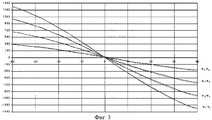
Сущность изобретения поясняется чертежами, где на фиг.1 изображен поперечный разрез приемной многоэлементной компенсированной антенны для глубоководного фазового батиметрического гидролокатора бокового обзора, на фиг.2 приведены экспериментальные амплитудные характеристики направленности каждой линейной антенны в поперечной плоскости, на фиг.3 приведены экспериментальные фазовые характеристики приемной антенны в поперечной плоскости. The invention is illustrated by drawings, where Fig. 1 shows a cross section of a receiving multi-element compensated antenna for a deep-sea phase bathymetric side-scan sonar, Fig. 2 shows the experimental amplitude directivity characteristics of each linear antenna in the transverse plane, Fig. 3 shows the experimental phase characteristics of the receiving antennas in the transverse plane.
Приемная многоэлементная компенсированная антенна для глубоководного фазового батиметрического гидролокатора бокового обзора (фиг.1) содержит корпус, включающий тыльную 1 и боковую 2 поверхности, несколько рядов прямоугольных пьезоэлементов 3, размещенных в этом корпусе. Каждый из рядов пьезоэлементов 3 представляет отдельную линейную антенну шириной менее λ/2 и длиной, равной длине приемной антенны. Причем отдельные линейные антенны размещены по ширине приемной антенны на расстоянии менее λ. Приемная антенна имеет тыльный экран, образованный тыльной поверхностью 1 корпуса антенны, выполненный из акустически жесткого материала, и слоем 4 из акустически мягкого материала. Тыльный экран расположен параллельно фронтальной поверхности приемной антенны. Зазоры между линейными антеннами 3, а также боковой поверхностью 2 корпуса приемной антенны и крайними линейными антеннами 3 заполнены экранирующим слоем 5 из акустически мягкого материала. Каждый зазор разделен по ширине на две части ребром 6 из акустически жесткого материала. Ширина этих частей зазора и ширина ребра 6 равны и выполнены меньше длины волны рабочей частоты λ. Высота ребра 6 выбирается из условия hm≈λm/2•m, а высота экранирующего слоя выбирается из условия hp≈λp/4•n, где λ, λm, λp - длина волны в рабочей среде, в акустически жестком и акустически мягком материалах соответственно, n=1,3..., m=1,2... В качестве акустически мягкого материала для тыльного экрана и экранирующего слоя использована резина, а в качестве акустически жесткого материала для тыльного экрана и ребра использован металл.A receiving multi-element compensated antenna for a deep-sea phase bathymetric side-scan sonar (Fig. 1) comprises a housing including a rear 1 and side 2 surfaces, several rows of rectangular piezoelectric elements 3 placed in this housing. Each of the rows of piezoelectric elements 3 represents a separate linear antenna with a width of less than λ / 2 and a length equal to the length of the receiving antenna. Moreover, individual linear antennas are placed across the width of the receiving antenna at a distance of less than λ. The receiving antenna has a back screen formed by the
Приемная многоэлементная компенсированная антенна для глубоководного фазового батиметрического гидролокатора бокового обзора работает следующим образом. The receiving multi-element compensated antenna for a deep-sea phase bathymetric side-scan sonar operates as follows.
Акустические сигналы, фазы которых содержат информацию о высоте отражателей на морском дне и пришедшие с произвольных направлений, принимаются поверхностями приемной антенны. В диапазоне углов 180±90 градусов уровень сигнала мал за счет обычного тыльного экранирования. В секторе 0±90 градусов акустические сигналы поступают из рабочей среды на фронтальную поверхность каждой отдельной линейной антенны. Кроме того, сигналы распространяются по поверхности и корпусу антенны. Вследствие того, что высота слоя из акустически мягкого материала выбрана равной hp≈λp/4•n, ее входной импеданс, определяемый формулой
при n=1,3... равен нулю.Acoustic signals whose phases contain information about the height of the reflectors on the seabed and come from arbitrary directions are received by the surfaces of the receiving antenna. In the range of angles of 180 ± 90 degrees, the signal level is small due to the usual rear screening. In a sector of 0 ± 90 degrees, acoustic signals come from the working medium to the frontal surface of each individual linear antenna. In addition, signals propagate along the surface and body of the antenna. Due to the fact that the height of the layer of acoustically soft material is chosen equal to hp ≈λp / 4 • n, its input impedance, determined by the formula
for n = 1.3 ... it is equal to zero.
Входной импеданс металлического ребра
при hm≈λm/2•m для m=1,2.. равен бесконечности. В результате для каждой из пяти отдельных линейных антенн получим идентичные условия акустического экранирования в виде полос одинаковой ширины с чередованием акустически мягкого и жесткого участков. Импеданс такой структуры не зависит от угла прихода сигнала. При таком выполнении заполняющего экрана взаимодействие между отдельными линейными антеннами отсутствует, характеристика направленности отдельной линейной антенны в поперечной плоскости определяется только ее шириной l
а фазовые характеристики отдельных линейных антенн относительно первой определяются только расстоянием между отдельными линейными антеннами d
где θ - угол прихода плоской волны относительно нормали антенны;
i=2, 3, 4, 5 - номер отдельной линейной антенны.Input rib impedance
when hm ≈λm / 2 • m for m = 1,2 .. is equal to infinity. As a result, for each of the five separate linear antennas, we obtain identical conditions for acoustic shielding in the form of strips of the same width with alternating acoustically soft and hard sections. The impedance of such a structure does not depend on the angle of arrival of the signal. With this embodiment of the filling screen, there is no interaction between the individual linear antennas, the directivity characteristic of an individual linear antenna in the transverse plane is determined only by its width l
and the phase characteristics of individual linear antennas relative to the first are determined only by the distance between the individual linear antennas d
where θ is the angle of arrival of the plane wave relative to the normal of the antenna;
i = 2, 3, 4, 5 - number of a separate linear antenna.
Экспериментальные амплитудные характеристики направленности каждой линейной антенны в поперечной плоскости приведены на фиг.2. Параметры кривых соответствуют условию (3). The experimental amplitude directivity characteristics of each linear antenna in the transverse plane are shown in figure 2. The parameters of the curves correspond to condition (3).
Экспериментальные фазовые характеристики приведены на фиг.3. Точками нанесены соответствующие теоретические значения, рассчитанные по формуле (4). The experimental phase characteristics are shown in figure 3. The dots show the corresponding theoretical values calculated by the formula (4).
Таким образом, в сравнении с прототипом в заявленной антенне обеспечена идентичность амплитудных и фазовых характеристик, что позволило увеличить угловое разрешение при обработке сигналов отдельных линейных антенн. Такое техническое решение дает возможность использовать приемную антенну для решения задач фазовой батиметрии при гидролокационной съемке рельефа морского дна. Thus, in comparison with the prototype in the claimed antenna, the amplitude and phase characteristics are identical, which allowed to increase the angular resolution when processing the signals of individual linear antennas. Such a technical solution makes it possible to use a receiving antenna to solve the problems of phase bathymetry when sonar surveying the topography of the seabed.
В настоящее время приемная многоэлементная компенсированная антенна для глубоководного батиметрического гидролокатора бокового обзора прошла испытания, показала хорошие результаты и включена в состав фазового БГБО, предназначенного для установки на автономных необитаемых подводных аппаратах, разрабатываемых в ИПМТ ДВО РАН. Currently, the receiving multi-element compensated antenna for the deep-sea bathymetric side-scan sonar has been tested, has shown good results and is included in the phase BBBO intended for installation on autonomous uninhabited underwater vehicles developed at IPMT FEB RAS.
Источники информации
1. Ph. Denbigh. Swath bathymetry- Principles of operation and an analysis of errors. - IEEE J. Oceanic Eng.., vol.14, p.298, No4, Оct. 1989.Sources of information
1. Ph. Denbigh Swath bathymetry- Principles of operation and an analysis of errors. - IEEE J. Oceanic Eng .., vol. 14, p. 298, No. 4, Oct. 1989.
2. X. Lurton. Swath bathymetry Using Phase Difference - Theoretical Analysis of Acoustical Measurement Precision - IEEE J. Oceanic Eng.., vol. 25, p.351-363, No3, Jul. 2000. 2. X. Lurton. Swath bathymetry Using Phase Difference - Theoretical Analysis of Acoustical Measurement Precision - IEEE J. Oceanic Eng .., vol. 25, p. 351-363, No3, Jul. 2000.
3. F. Le Clerc. Performance of Angle Estimation Methods Applied to Multibeam Swath Bathymetry. - Ocean-1994 France, vol.3, p.231-236. 3. F. Le Clerc. Performance of Angle Estimation Methods Applied to Multibeam Swath Bathymetry. - Ocean-1994 France, vol. 3, p. 231-236.
4. Guoliang Jin and Dajun Tang. Uncertainties of Differential Phase Estimation Associated with Interferometric Sonars. - IEEE J. Oceanic Eng.., vol.21, p.53-63, Nol, Jan. 1996. 4. Guoliang Jin and Dajun Tang. Uncertainties of Differential Phase Estimation Associated with Interferometric Sonars. - IEEE J. Oceanic Eng .., vol. 21, p. 53-63, Nol, Jan. 1996.
5. Weiqing Zhu, Feng Pan, Min Zhu, Xiangjun Zhang, Changhong Wang, Xiaodong Liu. The AUV 3D Acoustics Imaging Systems -Workshop on Sensors and Sensing Technology for Autonomous Ocean Systems. Hawaii, Oct., 2000. 5. Weiqing Zhu, Feng Pan, Min Zhu, Xiangjun Zhang, Changhong Wang, Xiaodong Liu. The AUV 3D Acoustics Imaging Systems -Workshop on Sensors and Sensing Technology for Autonomous Ocean Systems. Hawaii, Oct., 2000.
6. Свердлин Г.М. Гидроакустические преобразователи и антенны. - Л.: Судостроение, 1980, с. 178, рис.6.16 - прототип. 6. Sverdlin G.M. Hydroacoustic transducers and antennas. - L .: Shipbuilding, 1980, p. 178, Fig. 6.16 - prototype.
7. Н. М. Иванов. Фазовый синтез акустических антенных решеток с взаимодействующими элементами. - Акуст. Журнал, 1992, т. 38, вып.1, с. 65-69. 7. N. M. Ivanov. Phase synthesis of acoustic antenna arrays with interacting elements. - Acoustics. Journal, 1992, v. 38,
8. Смарышев М. Д., Добровольский Ю.Ю. Гидроакустические антенны. - Л.: Судостроение, 1984, с. 217. 8. Smaryshev M. D., Dobrovolsky Yu.Yu. Hydroacoustic antennas. - L .: Shipbuilding, 1984, p. 217.
9. Шабров А. А. Направленность одностороннего поршня в экране конечных размеров с переменным импедансом. - Акуст. Журнал, 1984, т. 30, вып.1, с. 114-117. 9. Shabrov A. A. Orientation of a one-sided piston in a finite-size screen with variable impedance. - Acoustics. Journal, 1984, v. 30,
10. Севрюгова Н.В. Звуковое поле вблизи плоской периодической структуры с импедансными полосами. - Акуст. Журнал, 1981, т. 27, вып.1, с. 138-142. 10. Sevryugova N.V. Sound field near a flat periodic structure with impedance bands. - Acoustics. Journal, 1981, v. 27,
11. Бреховских Л.М. Волны в слоистых средах. - М.: Наука, 1973, с. 13. 11. Brekhovskikh L.M. Waves in layered media. - M .: Nauka, 1973, p. thirteen.
12. Глазанов В.Е. Экранирование гидроакустических антенн. - Л.: Судостроение, 1986, с. 27. 12. Glazanov V.E. Shielding sonar antennas. - L .: Shipbuilding, 1986, p. 27.
Claims (4)
Translated fromRussianPriority Applications (1)
| Application Number | Priority Date | Filing Date | Title |
|---|---|---|---|
| RU2002115196ARU2209530C1 (en) | 2002-06-06 | 2002-06-06 | Compensated multielement receiving antenna for deep-bathymetric side-scan phased sonar |
Applications Claiming Priority (1)
| Application Number | Priority Date | Filing Date | Title |
|---|---|---|---|
| RU2002115196ARU2209530C1 (en) | 2002-06-06 | 2002-06-06 | Compensated multielement receiving antenna for deep-bathymetric side-scan phased sonar |
Publications (1)
| Publication Number | Publication Date |
|---|---|
| RU2209530C1true RU2209530C1 (en) | 2003-07-27 |
Family
ID=29211979
Family Applications (1)
| Application Number | Title | Priority Date | Filing Date |
|---|---|---|---|
| RU2002115196ARU2209530C1 (en) | 2002-06-06 | 2002-06-06 | Compensated multielement receiving antenna for deep-bathymetric side-scan phased sonar |
Country Status (1)
| Country | Link |
|---|---|
| RU (1) | RU2209530C1 (en) |
Cited By (6)
| Publication number | Priority date | Publication date | Assignee | Title |
|---|---|---|---|---|
| RU2303336C1 (en)* | 2005-12-26 | 2007-07-20 | Федеральное государственное унитарное предприятие "Центральный научно-исследовательский институт "Морфизприбор" | Hydro-acoustic multi-element antenna and piezo-electric rod transformer for such an antenna |
| RU2340916C1 (en)* | 2007-04-27 | 2008-12-10 | Евгений Андреевич Денесюк | Method of surveying bottom contour of water bodies and device to that end |
| RU2344435C1 (en)* | 2007-05-08 | 2009-01-20 | Институт проблем морских технологий Дальневосточного отделения Российской академии наук (ИПМТ ДВО РАН) | Method of navigational support of autonomous underwater robot controlled from control ship |
| RU2366104C1 (en)* | 2007-12-04 | 2009-08-27 | Открытое акционерное общество "Концерн "Центральный научно-исследовательский институт "Электроприбор" | Antenna module with digital output |
| CN105759257A (en)* | 2016-04-01 | 2016-07-13 | 中国船舶重工集团公司第七〇五研究所 | Deep sea side scan sonar array and manufacturing method |
| RU2596244C1 (en)* | 2015-08-10 | 2016-09-10 | Армен Ованесович Кочаров | Arctic underwater navigation system for driving and navigation support of water surface and underwater objects of navigation in constrained conditions of navigation |
Citations (11)
| Publication number | Priority date | Publication date | Assignee | Title |
|---|---|---|---|---|
| US3359537A (en)* | 1964-06-30 | 1967-12-19 | Westinghouse Electric Corp | Transducer |
| FR2290812A1 (en)* | 1974-11-08 | 1976-06-04 | Thomson Csf | ELECTROACOUSTIC TRANSDUCER FOR DEEP IMMERSION |
| FR2290813A1 (en)* | 1974-11-08 | 1976-06-04 | Thomson Csf | Pressure resistant electro-acoustic transducer - has transmitter or receiver device resisting hydrostatic pressure using special fluid |
| GB1580720A (en)* | 1976-08-03 | 1980-12-03 | France Armed Forces | Piezo electric transducers and acoustic antennae |
| FR2498867A1 (en)* | 1981-01-27 | 1982-07-30 | Tech Radioelect Electro Fs | Electroacoustic transducer for great depth - has piezoelectric discs and counterweight in container with double walls separated by gas under pressure |
| US4633119A (en)* | 1984-07-02 | 1986-12-30 | Gould Inc. | Broadband multi-resonant longitudinal vibrator transducer |
| WO1987005772A1 (en)* | 1986-03-19 | 1987-09-24 | The Secretary Of State For Defence In Her Britanni | Sonar transducers |
| DE4339798A1 (en)* | 1993-11-23 | 1995-05-24 | Stn Atlas Elektronik Gmbh | Electroacoustic transducer arrangement |
| RU2087082C1 (en)* | 1989-07-06 | 1997-08-10 | Центральный научно-исследовательский институт "Морфизприбор" | Multielement resonant sonar antenna |
| RU2121771C1 (en)* | 1996-06-18 | 1998-11-10 | Центральный научно-исследовательский институт "Морфизприбор" | Hydroacoustic transducer for antenna array |
| RU2166840C2 (en)* | 1998-12-29 | 2001-05-10 | Государственное унитарное предприятие "Центральный научно-исследовательский институт "Морфизприбор" | Hydroacoustic antenna |
- 2002
- 2002-06-06RURU2002115196Apatent/RU2209530C1/ennot_activeIP Right Cessation
Patent Citations (11)
| Publication number | Priority date | Publication date | Assignee | Title |
|---|---|---|---|---|
| US3359537A (en)* | 1964-06-30 | 1967-12-19 | Westinghouse Electric Corp | Transducer |
| FR2290812A1 (en)* | 1974-11-08 | 1976-06-04 | Thomson Csf | ELECTROACOUSTIC TRANSDUCER FOR DEEP IMMERSION |
| FR2290813A1 (en)* | 1974-11-08 | 1976-06-04 | Thomson Csf | Pressure resistant electro-acoustic transducer - has transmitter or receiver device resisting hydrostatic pressure using special fluid |
| GB1580720A (en)* | 1976-08-03 | 1980-12-03 | France Armed Forces | Piezo electric transducers and acoustic antennae |
| FR2498867A1 (en)* | 1981-01-27 | 1982-07-30 | Tech Radioelect Electro Fs | Electroacoustic transducer for great depth - has piezoelectric discs and counterweight in container with double walls separated by gas under pressure |
| US4633119A (en)* | 1984-07-02 | 1986-12-30 | Gould Inc. | Broadband multi-resonant longitudinal vibrator transducer |
| WO1987005772A1 (en)* | 1986-03-19 | 1987-09-24 | The Secretary Of State For Defence In Her Britanni | Sonar transducers |
| RU2087082C1 (en)* | 1989-07-06 | 1997-08-10 | Центральный научно-исследовательский институт "Морфизприбор" | Multielement resonant sonar antenna |
| DE4339798A1 (en)* | 1993-11-23 | 1995-05-24 | Stn Atlas Elektronik Gmbh | Electroacoustic transducer arrangement |
| RU2121771C1 (en)* | 1996-06-18 | 1998-11-10 | Центральный научно-исследовательский институт "Морфизприбор" | Hydroacoustic transducer for antenna array |
| RU2166840C2 (en)* | 1998-12-29 | 2001-05-10 | Государственное унитарное предприятие "Центральный научно-исследовательский институт "Морфизприбор" | Hydroacoustic antenna |
Cited By (7)
| Publication number | Priority date | Publication date | Assignee | Title |
|---|---|---|---|---|
| RU2303336C1 (en)* | 2005-12-26 | 2007-07-20 | Федеральное государственное унитарное предприятие "Центральный научно-исследовательский институт "Морфизприбор" | Hydro-acoustic multi-element antenna and piezo-electric rod transformer for such an antenna |
| RU2340916C1 (en)* | 2007-04-27 | 2008-12-10 | Евгений Андреевич Денесюк | Method of surveying bottom contour of water bodies and device to that end |
| RU2344435C1 (en)* | 2007-05-08 | 2009-01-20 | Институт проблем морских технологий Дальневосточного отделения Российской академии наук (ИПМТ ДВО РАН) | Method of navigational support of autonomous underwater robot controlled from control ship |
| RU2366104C1 (en)* | 2007-12-04 | 2009-08-27 | Открытое акционерное общество "Концерн "Центральный научно-исследовательский институт "Электроприбор" | Antenna module with digital output |
| RU2596244C1 (en)* | 2015-08-10 | 2016-09-10 | Армен Ованесович Кочаров | Arctic underwater navigation system for driving and navigation support of water surface and underwater objects of navigation in constrained conditions of navigation |
| CN105759257A (en)* | 2016-04-01 | 2016-07-13 | 中国船舶重工集团公司第七〇五研究所 | Deep sea side scan sonar array and manufacturing method |
| CN105759257B (en)* | 2016-04-01 | 2018-09-21 | 中国船舶重工集团公司第七一五研究所 | A kind of deep-sea side scan sonar basic matrix and preparation method |
Similar Documents
| Publication | Publication Date | Title |
|---|---|---|
| US11119211B2 (en) | Acoustic doppler system and method | |
| US11668820B2 (en) | Sonar data compression | |
| de MOUSTIER | State of the art in swath bathymetry survey systems | |
| US20100067330A1 (en) | Ship mounted underwater sonar system | |
| US12345839B2 (en) | Sonar system with adjusted beam | |
| US20220187452A1 (en) | Acoustic doppler system and method | |
| JP2014178320A (en) | Sonar transducer assembly | |
| US20210341601A1 (en) | Multimission and multispectral sonar | |
| CN110177325A (en) | Wideband electro-acoustic energy converter and wideband electro-acoustic array | |
| RU2209530C1 (en) | Compensated multielement receiving antenna for deep-bathymetric side-scan phased sonar | |
| US11194046B2 (en) | Multiple frequency side-scan sonar | |
| US6240050B1 (en) | Method of resetting sonar images using secondary antenna | |
| RU2840131C1 (en) | Acoustic doppler method of profiling currents in water medium | |
| Carter et al. | Sonar systems | |
| RU98254U1 (en) | MULTI-FREQUENCY CORRELATION HYDROACOUSTIC LAG | |
| RU179409U1 (en) | MULTI-ELEMENT ARC ANTENNA | |
| RU178896U1 (en) | ACOUSTIC HYDROLOCATION DEVICE | |
| Riegl et al. | Acoustic methods overview | |
| Jones et al. | 3 Acoustic Seabed Survey Methods, Analysis and Applications | |
| Wu | 2.1 Principle of Multi-beam Sounding Technology | |
| Huang et al. | The design of sidelobe suppressed PVDF beamforming elements for high performance underwater multi-beam swath transducers | |
| Voloshchenko et al. | The Underwater Ultrasonic Equipment with the Nonlinear Acoustics Effect’s Application | |
| JP2955422B2 (en) | Transducer and towing body | |
| Stergiopoulos | Sonar Systems |
Legal Events
| Date | Code | Title | Description |
|---|---|---|---|
| MM4A | The patent is invalid due to non-payment of fees | Effective date:20200607 |