RU2204418C2 - Syringe - Google Patents
SyringeDownload PDFInfo
- Publication number
- RU2204418C2 RU2204418C2RU2000122741/14ARU2000122741ARU2204418C2RU 2204418 C2RU2204418 C2RU 2204418C2RU 2000122741/14 ARU2000122741/14 ARU 2000122741/14ARU 2000122741 ARU2000122741 ARU 2000122741ARU 2204418 C2RU2204418 C2RU 2204418C2
- Authority
- RU
- Russia
- Prior art keywords
- tip
- injection needle
- syringe
- adapter
- insert
- Prior art date
Links
- 238000002347injectionMethods0.000claimsabstractdescription48
- 239000007924injectionSubstances0.000claimsabstractdescription48
- 230000003313weakening effectEffects0.000claimsdescription5
- 239000011324beadSubstances0.000abstract1
- 238000010276constructionMethods0.000abstract1
- 230000000694effectsEffects0.000abstract1
- 208000015181infectious diseaseDiseases0.000abstract1
- 239000000126substanceSubstances0.000abstract1
- 239000003814drugSubstances0.000description9
- 229940079593drugDrugs0.000description8
- 239000003708ampulSubstances0.000description2
- 239000002775capsuleSubstances0.000description2
- 230000000903blocking effectEffects0.000description1
- 230000006378damageEffects0.000description1
- 239000003292glueSubstances0.000description1
- 238000010438heat treatmentMethods0.000description1
Images


Landscapes
- Infusion, Injection, And Reservoir Apparatuses (AREA)
Abstract
Description
Translated fromRussianИзобретение относится к области медицинского оборудования, а более конкретно, к устройствам, предназначенным для разового введения (инъекции) лекарственных средств. The invention relates to the field of medical equipment, and more specifically, to devices intended for a single administration (injection) of drugs.
Известна шприц-ампула по а.с. 1018646, содержащая эластичную капсулу с лекарственным средством и инъекционную иглу. Заполнение капсулы лекарственным средством производится на предприятии-изготовителе, поэтому использование данной шприц-ампулы оправдано только для комплектования различных специализированных аптечек. Known syringe ampoule by A.S. 1018646 containing an elastic capsule with a drug and an injection needle. Filling the capsule with a drug is carried out at the manufacturer, so the use of this syringe ampoule is justified only for the acquisition of various specialized first-aid kits.
Известен также шприц по заявке а.с. 1801507, содержащий корпус с наконечником для присоединения инъекционной иглы, крышку с лепестками, поршень со ступенчатым штоком и размещенной на последнем втулкой. После выполнения инъекции лепестки крышки, взаимодействуя со ступенькой на штоке, блокируют шток с поршнем и препятствуют повторному набору лекарственного средства в корпус шприца. A syringe is also known at the request of A.S. 1801507, comprising a housing with a tip for attaching an injection needle, a cover with petals, a piston with a stepped rod and placed on the last sleeve. After the injection, the lid petals, interacting with a step on the stem, block the piston rod and prevent re-injection of the drug into the syringe body.
Недостатком данного шприца является то, что он, обеспечивая одноразовость использования корпуса шприца, в то же время не исключает возможности повторного использования инъекционной иглы. Объясняется это следующим. После выполнения инъекции и блокировки штока с поршнем в корпусе шприца инъекционная игла может быть отделена от наконечника корпуса и присоединена к наконечнику корпуса другого шприца, т.е. использована для повторной инъекции. The disadvantage of this syringe is that it, providing a one-time use of the body of the syringe, at the same time does not exclude the possibility of reuse of the injection needle. This is explained as follows. After the injection and blocking of the stem with the piston in the syringe body, the injection needle can be separated from the body tip and attached to the body tip of another syringe, i.e. used for re-injection.
Целью предлагаемого изобретения является исключение возможности последующего повторного использования инъекционной иглы. The aim of the invention is to eliminate the possibility of subsequent reuse of the injection needle.
Поставленная цель достигается тем, что на наконечнике между корпусом и головкой наконечника закреплен полый вкладыш, внутренняя и наружная поверхности которого контактируют соответственно с наружной поверхностью наконечника и внутренней поверхностью переходника инъекционной иглы. На внутренней поверхности вкладыша и его торце, взаимодействующем с корпусом, выполнены каналы, одни концы которых сообщены с атмосферой, а другие - перекрыты головкой наконечника. На наконечнике имеется кольцевое ослабление, а на внутренней поверхности переходника со стороны, противоположной инъекционной игле, выполнен буртик, взаимодействующий с пазом, выполненным на наружной поверхности вкладыша. Буртик обеспечивает возможность разрушения наконечника по кольцевому ослаблению и снятия вкладыша совместно с переходником при снятии инъекционной иглы с наконечника шприца. Инъекционная игла не может быть присоединена к наконечнику другого шприца ввиду наличия в ее переходнике вкладыша. При установке использованной инъекционной иглы на наконечник шприца с сорванной головкой наконечника и вкладышем внутренняя полость шприца будет сообщаться с атмосферой через каналы, имеющиеся на внутренней поверхности вкладыша и его торце, что делает инъекцию невозможной. This goal is achieved by the fact that a hollow insert is fixed on the tip between the body and the tip head, the inner and outer surfaces of which contact respectively the outer surface of the tip and the inner surface of the injection needle adapter. On the inner surface of the liner and its end interacting with the housing, channels are made, some ends of which are in communication with the atmosphere, while others are overlapped by the tip head. On the tip there is an annular weakening, and on the inner surface of the adapter from the side opposite the injection needle, a collar is made, interacting with a groove made on the outer surface of the liner. The collar provides the possibility of destruction of the tip by annular weakening and removal of the liner together with the adapter when removing the injection needle from the tip of the syringe. An injection needle cannot be attached to the tip of another syringe due to the presence of a liner in its adapter. When the used injection needle is installed on the tip of the syringe with a torn tip head and the liner, the inner cavity of the syringe will communicate with the atmosphere through the channels available on the inner surface of the liner and its end, which makes injection impossible.
Предлагаемое устройство поясняется на чертежах. The proposed device is illustrated in the drawings.
На фиг. 1 представлен продольный разрез предложенного шприца в исходном положении (перед началом забора лекарственного средства). In FIG. 1 shows a longitudinal section of the proposed syringe in the initial position (before the start of drug intake).
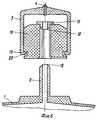
На фиг.2 показан выносной элемент I согласно фиг.1. Figure 2 shows the remote element I according to figure 1.
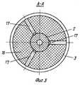
На фиг.3 показан разрез А-А согласно фиг.2. Figure 3 shows a section aa according to figure 2.
На фиг.4 представлен продольный разрез предложенного шприца перед выполнением инъекции (после сброса воздуха из подпоршневого пространства). Figure 4 presents a longitudinal section of the proposed syringe before performing the injection (after air discharge from the sub-piston space).
На фиг.5 представлен продольный разрез предложенного шприца после выполнения инъекции (при попытке повторного набора лекарственного средства). Figure 5 presents a longitudinal section of the proposed syringe after the injection (when trying to re-dial the drug).
На фиг.6 показан продольный разрез наконечника и инъекционной иглы предложенного шприца после снятия инъекционной иглы с наконечника шприца. Figure 6 shows a longitudinal section of the tip and injection needle of the proposed syringe after removing the injection needle from the tip of the syringe.
На фиг.7 показан продольный разрез наконечника другого шприца и инъекционной иглы при попытке повторной установки инъекционной иглы на наконечник. 7 shows a longitudinal section of the tip of another syringe and injection needle while trying to re-install the injection needle on the tip.
На фиг. 8 показан продольный разрез наконечника и инъекционной иглы предложенного шприца после повторной установки инъекционной иглы на наконечник шприца со снятым вкладышем. In FIG. 8 shows a longitudinal section through the tip and injection needle of the proposed syringe after re-installing the injection needle on the tip of the syringe with the liner removed.
Шприц содержит корпус 1 (фиг.1) с наконечником 2, на котором посредством переходника 3 установлена инъекционная игла 4, подвижно размещенный в корпусе 1 поршень 5 со ступенчатым штоком 6, на ступени меньшего сечения которого подвижно установлена втулка 7 и закреплена рукоятка 8. Со стороны, противоположной наконечнику 2, корпус 1 закрыт крышкой 9, имеющей центральное отверстие 10. В центральном отверстии 10 размещена втулка 7, а по краям центрального отверстия 10 выполнены наружные 11 и внутренние лепестки 12. Причем внутренние лепестки 12 взаимодействуют с наружной поверхностью втулки 7 и имеют возможность взаимодействия со ступенькой 13 штока 6, а наружные лепестки 11 имеют возможность взаимодействия с торцом 14 втулки 7. На наконечнике 2 (фиг.1, 2) между корпусом 1 и головкой 15 наконечника 2 закреплен полый вкладыш 16, внутренняя и наружная поверхности которого контактируют соответственно с наружной поверхностью наконечника 2 и внутренней поверхностью переходника 3 инъекционной иглы 4. На внутренней поверхности вкладыша 16 и его торце, взаимодействующем с корпусом 1, выполнены каналы 17, одни концы которых сообщены с атмосферой, а другие - перекрыты головкой 15 наконечника 2. На наконечнике 2 имеется кольцевое ослабление 18, а на внутренней поверхности переходника 3 со стороны, противоположной инъекционной игле 4, выполнен буртик 19, взаимодействующий с пазом 20, выполненным на наружной поверхности вкладыша 16. The syringe comprises a housing 1 (Fig. 1) with a
Сборка шприца проводится на предприятии-изготовителе в следующей последовательности. The syringe assembly is carried out at the manufacturer in the following sequence.
На наконечник 2 устанавливается вкладыш 16 и внешний край наконечника 2 подвергается термообработке (оплавляется) при этом формируется головка 15 наконечника 2. Поршень 5 (фиг.1), соединенный со штоком 6, вводится в корпус 1 шприца, и на ступень штока 6 меньшего сечения устанавливается втулка 7 и технологическая коническая втулка (на чертежах условно не показана). На шток 6 центральным отверстием 10 устанавливается крышка 9, внутренние лепестки 12 которой расходятся, контактируя с наружной поверхностью технологической конической втулки. Крышка 10 крепится (клеем или термообработкой) к фланцу корпуса 1. Затем удаляется технологическая коническая втулка и к штоку 6 прикрепляется рукоятка 8. An
Присоединение инъекционной иглы 4 к наконечнику 2 шприца может производиться как на предприятии-изготовителе, так и пользователем непосредственно перед выполнением инъекции. Attachment of the
Шприц функционирует следующим образом. The syringe operates as follows.
При наборе лекарственного средства 21 в корпус 1 (фиг.4) при вытягивании штока 6 втулка 7 разводит наружные лепестки 11 и выходит из центрального отверстия 10 крышки 9. Внутренние лепестки 12 контактируют с наружной поверхностью ступени штока 6 большего сечения и не препятствуют перемещению штока 6. После набора необходимой дозы лекарственного средства 21 из подпоршневого пространства сбрасывается воздух и производится инъекция. Незадолго до окончания выполнения инъекции наружные лепестки 11 (фиг.4, 5) взаимодействуют с торцом 14 втулки 7 и препятствуют ее заходу в центральное отверстие 10 крышки 9, а внутренние лепестки 12 срываются с наружной поверхности ступени штока 6 большего сечения после прохождения под концами внутренних лепестков 12 ступеньки 13 штока 6. Повторный набор лекарственного средства 21 в корпус 1 (фиг.5) шприца невозможен ввиду того, что внутренние лепестки 12 взаимодействуют со ступенькой 13 на штоке 6 и не позволяют вытянуть шток 6 из корпуса 1. When collecting medicine 21 into the housing 1 (Fig. 4), when the
При снятии инъекционной иглы 4 (фиг.2, 6) с наконечника 2 предлагаемого шприца переходник 3 через буртик 19 воздействует на паз 20 вкладыша 16, а последний, в свою очередь, воздействует на головку 15 наконечника 2. При создании определенного усилия происходит разрушение наконечника 2 по кольцевому ослаблению 18 и переходник 3 инъекционной иглы отделяется от наконечника 2 вместе со вкладышем 16 и головкой 15. Снятая таким образом инъекционная игла 3 не может быть использована повторно для инъекции ввиду невозможности ее установки на наконечник 2 (фиг.7) со вкладышем 16 другого шприца из-за наличия в переходнике 3 использованной инъекционной иглы 4 вкладыша 16. Попытка повторно использовать инъекционную иглу 4 (фиг.8) после присоединения ее к наконечнику 2 предлагаемого шприца, с которого удален вкладыш 16 и наконечник 2 разрушен по кольцевому ослаблению 18, будет также невозможна, так как через каналы 17, имеющиеся на внутренней поверхности вкладыша и его торце, внутренняя полость шприца будет сообщаться с атмосферой. When removing the injection needle 4 (figure 2, 6) from the
Таким образом, предложенное устройство имеет существенные отличия от ранее известных шприцов и позволяет исключить возможность повторного использования инъекционной иглы. Thus, the proposed device has significant differences from previously known syringes and eliminates the possibility of reuse of the injection needle.
Claims (1)
Translated fromRussianPriority Applications (1)
| Application Number | Priority Date | Filing Date | Title |
|---|---|---|---|
| RU2000122741/14ARU2204418C2 (en) | 2000-08-30 | 2000-08-30 | Syringe |
Applications Claiming Priority (1)
| Application Number | Priority Date | Filing Date | Title |
|---|---|---|---|
| RU2000122741/14ARU2204418C2 (en) | 2000-08-30 | 2000-08-30 | Syringe |
Publications (2)
| Publication Number | Publication Date |
|---|---|
| RU2000122741A RU2000122741A (en) | 2002-07-27 |
| RU2204418C2true RU2204418C2 (en) | 2003-05-20 |
Family
ID=20239670
Family Applications (1)
| Application Number | Title | Priority Date | Filing Date |
|---|---|---|---|
| RU2000122741/14ARU2204418C2 (en) | 2000-08-30 | 2000-08-30 | Syringe |
Country Status (1)
| Country | Link |
|---|---|
| RU (1) | RU2204418C2 (en) |
Citations (4)
| Publication number | Priority date | Publication date | Assignee | Title |
|---|---|---|---|---|
| SU156023A1 (en)* | Специальное Конструкторское Бюро | GAZSTROYMASHINA "GLAVGAZA USSR | ||
| US4966593A (en)* | 1989-03-06 | 1990-10-30 | Design Specialties Laboratories | Disposable hypodermic syringe with retractable needle |
| US4973316A (en)* | 1990-01-16 | 1990-11-27 | Dysarz Edward D | One handed retractable safety syringe |
| SU1774874A3 (en)* | 1987-07-10 | 1992-11-07 | Zhak Verle | Syringe |
- 2000
- 2000-08-30RURU2000122741/14Apatent/RU2204418C2/ennot_activeIP Right Cessation
Patent Citations (4)
| Publication number | Priority date | Publication date | Assignee | Title |
|---|---|---|---|---|
| SU156023A1 (en)* | Специальное Конструкторское Бюро | GAZSTROYMASHINA "GLAVGAZA USSR | ||
| SU1774874A3 (en)* | 1987-07-10 | 1992-11-07 | Zhak Verle | Syringe |
| US4966593A (en)* | 1989-03-06 | 1990-10-30 | Design Specialties Laboratories | Disposable hypodermic syringe with retractable needle |
| US4973316A (en)* | 1990-01-16 | 1990-11-27 | Dysarz Edward D | One handed retractable safety syringe |
Similar Documents
| Publication | Publication Date | Title |
|---|---|---|
| US5993417A (en) | Disposable syringe with an automatically retractable hypodermic needle | |
| EP0337252B1 (en) | Safety syringe | |
| RU2217175C1 (en) | Disposable injection device | |
| JP2644568B2 (en) | Disposable hypodermic syringe | |
| AU685145B2 (en) | Cartridge-needle unit having retractable needle | |
| ES2301638T3 (en) | SECURITY PROTECTIVE SYSTEM FOR PRE-FILLED SYRINGES. | |
| KR960005816B1 (en) | Anti-needle strike and anti-drug abuse syringe | |
| US4944723A (en) | Universal disposable safety syringe system | |
| EP1092443B1 (en) | Retracting needle syringe | |
| JP5030593B2 (en) | Safety shield system for prefilled syringes | |
| US4699614A (en) | Non-reusable syringe | |
| US4767413A (en) | Dental syringe having an automatically retractable needle | |
| US7815610B2 (en) | Injection apparatus | |
| RO116949B1 (en) | UNIT DEVICE FOR IMPLANT INJECTION | |
| CA2126440A1 (en) | Safety syringe | |
| JP2002533173A (en) | Disposable syringe with separation plunger | |
| MX2007000146A (en) | Single-use syringe. | |
| WO1999037346A1 (en) | Single-use syringe | |
| JPH0649073B2 (en) | Hypodermic syringe | |
| EP0649318A1 (en) | Syringe for medicinal purposes | |
| US4950253A (en) | Needle ejector structure for a syringe | |
| US5554126A (en) | Multiple purpose protective hypodermic needle cap | |
| CN110691622B (en) | Safety needle with deformable cannula for injection pen | |
| US4816021A (en) | Self-destructing hypodermic syringes and hypodermic plunger devices | |
| RU2204418C2 (en) | Syringe |
Legal Events
| Date | Code | Title | Description |
|---|---|---|---|
| MM4A | The patent is invalid due to non-payment of fees | Effective date:20040831 |