RU2200869C2 - Fuel injection nozzle with prechamber - Google Patents
Fuel injection nozzle with prechamberDownload PDFInfo
- Publication number
- RU2200869C2 RU2200869C2RU2000126110/06ARU2000126110ARU2200869C2RU 2200869 C2RU2200869 C2RU 2200869C2RU 2000126110/06 ARU2000126110/06 ARU 2000126110/06ARU 2000126110 ARU2000126110 ARU 2000126110ARU 2200869 C2RU2200869 C2RU 2200869C2
- Authority
- RU
- Russia
- Prior art keywords
- fuel
- prechamber
- nozzle
- mixture
- engine
- Prior art date
Links
Images


Landscapes
- Combustion Methods Of Internal-Combustion Engines (AREA)
Abstract
Description
Translated fromRussianИзобретение относится к двигателестроению, а именно к двигателям внутреннего строения с искровым зажиганием топливовоздушной смеси. The invention relates to engine building, and in particular to internal structure engines with spark ignition of an air-fuel mixture.
Целью изобретения является повышение топливной экономичности и снижение токсичности отработанных газов двигателя внутреннего сгорания. The aim of the invention is to increase fuel efficiency and reduce the toxicity of exhaust gases of an internal combustion engine.
Известен двигатель, содержащий камеру сгорания, образованную в цилиндре его головкой и поршнем, форкамеру, соединенную с камерой сгорания каналом, снабженную свечой зажигания и форсункой для впрыска топлива через форкамеру в камеру сгорания (SU 1359447 А1). Форсунка для впрыска топлива с форкамерой позволяет реализовать данный способ работы двигателя внутреннего сгорания. A known engine comprising a combustion chamber formed in the cylinder by its head and piston, a prechamber connected to the combustion chamber by a channel, equipped with a spark plug and an injector for injecting fuel through the prechamber into the combustion chamber (SU 1359447 A1). A nozzle for fuel injection with a pre-chamber allows you to implement this method of operation of an internal combustion engine.
Наиболее близким техническим решением является решение по патенту GB 2011539 А. В данном техническом решении говорится о форсунке для впрыска топлива или топливовоздушной смеси непосредственно в камеру сгорания двигателя, установленной между головкой цилиндра и свечой зажигания. Дополнительную топливовоздушную смесь вводят в камеру сгорания двигателя через снабженный клапаном канал под электрод свечи зажигания. Для работы двигателя необходимы два канала формирования и дозирования топливовоздушной смеси. The closest technical solution is the solution according to patent GB 2011539 A. This technical solution refers to an injector for injecting fuel or air-fuel mixture directly into the combustion chamber of an engine installed between the cylinder head and the spark plug. An additional air-fuel mixture is introduced into the combustion chamber of the engine through a channel provided with a valve under the spark plug electrode. For the engine to work, two channels of formation and dosing of the air-fuel mixture are required.
В отличие от прототипа форсунка для впрыска топлива с форкамерой позволяет в широких пределах регулировать качество топливовоздушной смеси в камере сгорания и автоматически формировать топливовоздушную смесь необходимого качества в области искрового промежутка свечи зажигания. In contrast to the prototype, a nozzle for injecting fuel with a pre-chamber allows a wide control of the quality of the air-fuel mixture in the combustion chamber and the formation of the air-fuel mixture of the required quality in the spark gap of the spark plug.
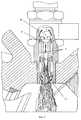
Расположение форсунки с форкамерой на двигателе показано на фиг.1, где 1,1 - форсунка с форкамерой, 1,2 - свеча зажигания, 1,3 - головка цилиндра, 1,4 - поршень. The location of the nozzle with the prechamber on the engine is shown in Fig. 1, where 1.1 is the nozzle with the prechamber, 1.2 is the spark plug, 1.3 is the cylinder head, 1.4 is the piston.
Конструкция форсунки с форкамерой изображена на фиг.2 и фиг.3, где 1 - корпус, 2 - распределительная втулка, 3 - топливо подводящая муфта, 4 - шайба, 5 - гайка, 6 - три сопла, 7 - топливные каналы, 8 - основной соединительный канал, 9 - три дополнительных соединительных канала, 10 - форкамера, образованная корпусом форсунки и свечой зажигания. The nozzle design with a pre-chamber is shown in FIG. 2 and FIG. 3, where 1 is a housing, 2 is a distribution sleeve, 3 is a fuel inlet sleeve, 4 is a washer, 5 is a nut, 6 is three nozzles, 7 are fuel channels, 8 is main connecting channel, 9 - three additional connecting channels, 10 - prechamber formed by the nozzle body and the spark plug.
Работу двигателя с форсункой поясняет фиг.4 и фиг.5. The operation of the engine with the nozzle is illustrated in figure 4 and figure 5.
Всасывающий коллектор двигателя необходимо выполнить без дроссельной заслонки, с наименьшим аэродинамическим сопротивлением для более полного наполнения цилиндра воздухом. The intake manifold of the engine must be performed without a throttle, with the lowest aerodynamic resistance for more complete filling of the cylinder with air.
В процессе такта всасывания (фиг.4) происходит наполнение цилиндра воздухом и очищение форкамеры 10, основного соединительного канала 8 и трех дополнительных соединительных каналов 9 от продуктов сгорания предыдущего рабочего хода, а также смешивание их с воздухом, заполняющим цилиндр. В конце такта всасывания - начале такта сжатия производится впрыск топлива из трех сопел, расположенных в основном соединительном канале форсунки (фиг.5). Сопла направлены в сторону камеры сгорания и встречно друг к другу таким образом, чтобы обеспечить соударение топливных факелов 11 из них на выходе из основного соединительного канала. В результате суммарный топливный факел получает сложную форму, что способствует образованию однородной топливовоздушной смеси в камере сгорания. В то же время богатая топливовоздушная смесь из поверхностных слоев топливных факелов по трем дополнительным соединительным каналам 9 заполняет форкамеру 10. Дополнительные соединительные каналы расположены вокруг основного канала параллельно ему. Качество смеси, циркулирующей в форкамере 10 по основному 8 и трем дополнительным 9 соединительным каналам, остается неизменным и не зависит от длительности (количества топлива) впрыска. В конце такта сжатия богатая топливовоздушная смесь в форкамере воспламеняется искрой свечи зажигания. Пламя, распространяясь по основному и дополнительным каналам, устремляется в камеру сгорания. Факел пламени на выходе из форсунки имеет опять же сложную форму, что способствует лучшему воспламенению бедной смеси в камере сгорания и позволяет избежать местного перегрева поршня. During the suction stroke (Fig. 4), the cylinder is filled with air and the
Объем форкамеры и каналов в форсунке должен обеспечивать нагрев бедной смеси в камере сгорания до температуры вспышки топлива в ней (3-5% от объема камеры). В зависимости от режима работы двигателя меняется качество топливовоздушной смеси в камере сгорания, качество смеси в форкамере остается неизменным. Таким образом, на малых и средних нагрузках двигатель работает на бедной топливовоздушной смеси, меняется количество теплоты, подведенной к неизменному количеству рабочего тела, что на малых и средних нагрузках уменьшает потери тепла и облегчает тепловой режим двигателя. The volume of the prechamber and the channels in the nozzle must ensure that the lean mixture in the combustion chamber is heated to the flash point of the fuel in it (3-5% of the chamber volume). Depending on the engine operating mode, the quality of the air-fuel mixture in the combustion chamber changes, the quality of the mixture in the prechamber remains unchanged. Thus, at low and medium loads, the engine runs on a lean air-fuel mixture, the amount of heat supplied to the constant amount of the working fluid changes, which at low and medium loads reduces heat loss and facilitates the thermal regime of the engine.
Применение форсунки с форкамерой позволяет добиться полного сгорания топлива и снизить токсичность по СО в сравнение с карбюраторным двигателем (качественное регулирование смеси, продукты неполного сгорания из форкамеры дожигаются в следующем рабочем ходе двигателя), а также токсичность по NО# в сравнении с дизелем (низкая степень сжатия). Кроме того, при незначительных изменениях в головке цилиндров позволяет конвертировать выпускаемые промышленностью карбюраторные двигатели внутреннего сгорания.The use of a nozzle with a prechamber allows achieving complete combustion of fuel and reducing CO toxicity in comparison with a carburetor engine (high-quality regulation of the mixture, products of incomplete combustion from the prechamber are burned out in the next engine operation), as well as NO# toxicity compared to a diesel engine (low degree compression). In addition, with minor changes in the cylinder head, it is possible to convert carburetor internal combustion engines manufactured by the industry.
Claims (1)
Translated fromRussianPriority Applications (1)
| Application Number | Priority Date | Filing Date | Title |
|---|---|---|---|
| RU2000126110/06ARU2200869C2 (en) | 2000-10-16 | 2000-10-16 | Fuel injection nozzle with prechamber |
Applications Claiming Priority (1)
| Application Number | Priority Date | Filing Date | Title |
|---|---|---|---|
| RU2000126110/06ARU2200869C2 (en) | 2000-10-16 | 2000-10-16 | Fuel injection nozzle with prechamber |
Publications (2)
| Publication Number | Publication Date |
|---|---|
| RU2000126110A RU2000126110A (en) | 2002-09-10 |
| RU2200869C2true RU2200869C2 (en) | 2003-03-20 |
Family
ID=20241092
Family Applications (1)
| Application Number | Title | Priority Date | Filing Date |
|---|---|---|---|
| RU2000126110/06ARU2200869C2 (en) | 2000-10-16 | 2000-10-16 | Fuel injection nozzle with prechamber |
Country Status (1)
| Country | Link |
|---|---|
| RU (1) | RU2200869C2 (en) |
Cited By (2)
| Publication number | Priority date | Publication date | Assignee | Title |
|---|---|---|---|---|
| RU2541478C2 (en)* | 2010-04-28 | 2015-02-20 | Сименс Акциенгезелльшафт | Injector system and method of injector system damping |
| RU2705346C1 (en)* | 2017-12-27 | 2019-11-06 | Тойота Дзидося Кабусики Кайся | Internal combustion engine |
Citations (12)
| Publication number | Priority date | Publication date | Assignee | Title |
|---|---|---|---|---|
| SU64788A1 (en)* | 1943-09-02 | 1945-05-31 | Н.А. Губанов | Pre-chamber for internal combustion engine |
| US3884211A (en)* | 1972-06-30 | 1975-05-20 | Honda Motor Co Ltd | Combustion chamber device for an internal combustion engine |
| DE2641377A1 (en)* | 1976-09-15 | 1978-03-16 | Kloeckner Humboldt Deutz Ag | Cylinder head for piston IC engine - has hood closing off oil containing chambers and fuel injection valve projecting into antechamber |
| US4095580A (en)* | 1976-10-22 | 1978-06-20 | The United States Of America As Represented By The United States Department Of Energy | Pulse-actuated fuel-injection spark plug |
| GB2011539A (en)* | 1977-12-24 | 1979-07-11 | Franke W | Pollution and ignition control in an internal combustion engine |
| SU903577A1 (en)* | 1980-05-08 | 1982-02-07 | Войсковая часть 52609 | Compression-ignited i.c. engine |
| GB2101207A (en)* | 1981-06-27 | 1983-01-12 | Bosch Gmbh Robert | A pre-chamber for a combustion engine |
| SU1511448A1 (en)* | 1986-09-19 | 1989-09-30 | Московский карбюраторный завод | Supply system for ic-engine |
| DE4041443A1 (en)* | 1990-12-21 | 1992-07-02 | Mak Maschinenbau Krupp | INTERNAL COMBUSTION ENGINE, ESPECIALLY DIESEL ENGINE |
| RU2017991C1 (en)* | 1991-10-09 | 1994-08-15 | Товарищество с ограниченной ответственностью "АДВИ-АЛМАС" | Internal combustion engine with compression ignition |
| EP0632198A1 (en)* | 1993-06-30 | 1995-01-04 | Ngk Spark Plug Co., Ltd | A spark plug having a fuel injector valve |
| US5497744A (en)* | 1993-11-29 | 1996-03-12 | Toyota Jidosha Kabushiki Kaisha | Fuel injector with an integrated spark plug for a direct injection type engine |
- 2000
- 2000-10-16RURU2000126110/06Apatent/RU2200869C2/ennot_activeIP Right Cessation
Patent Citations (12)
| Publication number | Priority date | Publication date | Assignee | Title |
|---|---|---|---|---|
| SU64788A1 (en)* | 1943-09-02 | 1945-05-31 | Н.А. Губанов | Pre-chamber for internal combustion engine |
| US3884211A (en)* | 1972-06-30 | 1975-05-20 | Honda Motor Co Ltd | Combustion chamber device for an internal combustion engine |
| DE2641377A1 (en)* | 1976-09-15 | 1978-03-16 | Kloeckner Humboldt Deutz Ag | Cylinder head for piston IC engine - has hood closing off oil containing chambers and fuel injection valve projecting into antechamber |
| US4095580A (en)* | 1976-10-22 | 1978-06-20 | The United States Of America As Represented By The United States Department Of Energy | Pulse-actuated fuel-injection spark plug |
| GB2011539A (en)* | 1977-12-24 | 1979-07-11 | Franke W | Pollution and ignition control in an internal combustion engine |
| SU903577A1 (en)* | 1980-05-08 | 1982-02-07 | Войсковая часть 52609 | Compression-ignited i.c. engine |
| GB2101207A (en)* | 1981-06-27 | 1983-01-12 | Bosch Gmbh Robert | A pre-chamber for a combustion engine |
| SU1511448A1 (en)* | 1986-09-19 | 1989-09-30 | Московский карбюраторный завод | Supply system for ic-engine |
| DE4041443A1 (en)* | 1990-12-21 | 1992-07-02 | Mak Maschinenbau Krupp | INTERNAL COMBUSTION ENGINE, ESPECIALLY DIESEL ENGINE |
| RU2017991C1 (en)* | 1991-10-09 | 1994-08-15 | Товарищество с ограниченной ответственностью "АДВИ-АЛМАС" | Internal combustion engine with compression ignition |
| EP0632198A1 (en)* | 1993-06-30 | 1995-01-04 | Ngk Spark Plug Co., Ltd | A spark plug having a fuel injector valve |
| US5497744A (en)* | 1993-11-29 | 1996-03-12 | Toyota Jidosha Kabushiki Kaisha | Fuel injector with an integrated spark plug for a direct injection type engine |
Cited By (2)
| Publication number | Priority date | Publication date | Assignee | Title |
|---|---|---|---|---|
| RU2541478C2 (en)* | 2010-04-28 | 2015-02-20 | Сименс Акциенгезелльшафт | Injector system and method of injector system damping |
| RU2705346C1 (en)* | 2017-12-27 | 2019-11-06 | Тойота Дзидося Кабусики Кайся | Internal combustion engine |
Similar Documents
| Publication | Publication Date | Title |
|---|---|---|
| CN105317573B (en) | Fuel-injecting method for in-cylinder direct-jet combustion system | |
| CN111164285B (en) | Internal combustion engine for a motor vehicle | |
| CN100398793C (en) | Internal combustion engine with gaseous fuel injection | |
| US9909489B1 (en) | Piston fluid passages for reduced soot | |
| US20160169086A1 (en) | Combustion chamber with ducts for internal combustion engines | |
| US4237827A (en) | Swirl-chamber diesel engine with piston formed with curved groove at its crown | |
| AU2016217589B2 (en) | Injection system for two-stroke engines | |
| US7201135B2 (en) | Internal combustion engine | |
| US20070125337A1 (en) | Petrol internal combustion engine with controlled ignition and a very high pressure injection system | |
| RU2200869C2 (en) | Fuel injection nozzle with prechamber | |
| KR102078882B1 (en) | Injector configuration of a cylinder head of a dual fuel internal combustion engine | |
| KR100306600B1 (en) | Piston for direct injection type gasoline engine | |
| KR100828749B1 (en) | Direct injection engine | |
| CN109184926A (en) | A kind of dual fuel engine burner and method based on crosspointer valve fuel injector | |
| CN112832904A (en) | A small multi-fuel triangular rotary engine and its working mode | |
| KR100251914B1 (en) | Apparatus for swirling of intake for combustion chamber in diesel engines | |
| RU2717201C1 (en) | Internal combustion engine | |
| Ganesan | Combustion Aspects of Non-Conventional Reciprocating Internal Combustion Engines | |
| SU886758A3 (en) | Internal combustion engine | |
| JP2004251194A (en) | Gas engine | |
| WO2024201934A1 (en) | Internal combustion engine with auxiliary combustion chamber | |
| RU2044897C1 (en) | Internal combustion engine | |
| WO2024201933A1 (en) | Internal combustion engine with auxiliary combustion chamber | |
| CN116292015A (en) | Compression ignition system with multi-point heating ring | |
| WO2024201935A1 (en) | Internal combustion engine with auxiliary combustion chamber |
Legal Events
| Date | Code | Title | Description |
|---|---|---|---|
| MM4A | The patent is invalid due to non-payment of fees | Effective date:20041017 |