RU2192667C2 - Facsimile signal identifying device - Google Patents
Facsimile signal identifying deviceDownload PDFInfo
- Publication number
- RU2192667C2 RU2192667C2RU2000113767ARU2000113767ARU2192667C2RU 2192667 C2RU2192667 C2RU 2192667C2RU 2000113767 ARU2000113767 ARU 2000113767ARU 2000113767 ARU2000113767 ARU 2000113767ARU 2192667 C2RU2192667 C2RU 2192667C2
- Authority
- RU
- Russia
- Prior art keywords
- unit
- calculation unit
- input
- block
- output
- Prior art date
Links
Images
Landscapes
- Facsimiles In General (AREA)
- Telephonic Communication Services (AREA)
Abstract
Description
Translated fromRussianИзобретение относится к области электросвязи, в частности к средствам автоматической диагностики коммуникационного и канального оборудования в многоканальных системах телефонной связи. Данное изобретение может использоваться, например, в составе сервисных аппаратно-программных средств анализа трафика соединительных трактов. The invention relates to the field of telecommunications, in particular to means for automatic diagnostics of communication and channel equipment in multi-channel telephone communication systems. This invention can be used, for example, as part of service hardware-software means for analyzing the traffic of the connecting paths.
Для выделения факсимильных сигналов в каналах связи используется достаточно широкий спектр устройств. Так, например, в ряде устройств, таких как /1/, различение речевых сигналов с сигналами факсимильных передач осуществляется на основе известного различия в спектрах этих сигналов. В состав устройства входит блок согласования с каналом связи, аналого-цифровой преобразователь, два полосовых фильтра: один настроенный на низкочастотный диапазон канала связи (порядка 300-900 Гц), а другой на среднюю часть частотного диапазона, два пороговых элемента, логический элемент И и блок принятия решения. К сожалению, данное устройство не обеспечивает высокую точность различения сигналов из-за больших различий в статистических свойствах речевого сигнала. A fairly wide range of devices is used to highlight fax signals in communication channels. So, for example, in a number of devices, such as / 1 /, the distinction between speech signals and facsimile signals is based on a known difference in the spectra of these signals. The device includes a matching unit with a communication channel, an analog-to-digital converter, two band-pass filters: one tuned to the low-frequency range of the communication channel (of the order of 300-900 Hz), and the other to the middle part of the frequency range, two threshold elements, logical element And and decision block. Unfortunately, this device does not provide high accuracy of distinguishing signals due to large differences in the statistical properties of the speech signal.
Известно также устройство /2/, называемое дискриминатором сигналов речи и данных, в основу работы которого положено отличие значения автокорреляционной функции и нормированного момента второго порядка для речи и факсимильного сигнала. Данное устройство наиболее близко по своей технической сущности к заявляемому. Дискриминатор сигналов речи и данных содержит блок согласования с каналом связи, аналого-цифровой преобразователь, линию задержки, умножитель, первый, второй и третий интеграторы, первый и второй пороговые элементы, первый и второй квадраторы, блок вычисления отношения, логический элемент И и блок принятия решения. Однако такое устройство не обеспечивает необходимой точности идентификации факсимильного сигнала, что связано с большой нестационарностью речевого сигнала, и, как следствие, появление ложных срабатываний. Наиболее высока вероятность ошибки на участках речи, содержащих шипящие звуки. There is also a device / 2 /, called the discriminator of speech and data signals, which is based on the difference between the values of the autocorrelation function and the normalized second-order moment for speech and facsimile signal. This device is the closest in its technical essence to the claimed. The discriminator of speech and data signals contains a matching unit with a communication channel, an analog-to-digital converter, a delay line, a multiplier, first, second and third integrators, first and second threshold elements, first and second quadrators, a ratio calculation unit, an AND logic element, and an acceptance unit solutions. However, such a device does not provide the necessary accuracy of identifying a facsimile signal, which is associated with a large non-stationarity of the speech signal, and, as a consequence, the appearance of false responses. The highest probability of error in areas of speech containing hissing sounds.
Целью изобретения является повышение точности при идентификации вида передаваемых сигналов. The aim of the invention is to improve the accuracy in identifying the type of transmitted signals.
Для достижения поставленной цели в устройство для идентификации факсимильных сигналов, содержащее блок согласования с каналом связи, интегрирующее звено, первый и второй пороговые элементы, логический элемент И и блок принятия решения, согласно изобретению дополнительно введены полосовой фильтр, блок вычисления абсолютного значения, блок вычисления преобразования Фурье, арифметический блок, первый, второй, третий и четвертый блоки вычисления дисперсии, сумматор, третий пороговый элемент, причем выход блока согласования с каналом связи через полосовой фильтр связан с входами первого блока вычисления абсолютного значения и блока вычисления преобразования Фурье, а выход первого блока вычисления абсолютного значения через последовательно включенные первое интегрирующее звено и первый пороговый элемент подключен к первому входу логического элемента И, тогда как первый выход блока вычисления преобразования Фурье через последовательно соединенные арифметический блок, первый блок вычисления дисперсии и второй пороговый элемент соединен со вторым входом логического элемента И, при этом второй, третий и четвертый выходы блока вычисления преобразования Фурье через соответственно второй, третий и четвертый блоки вычисления дисперсии связаны с первым, вторым и третьим входами сумматора, который в свою очередь через третий пороговый элемент подключен к третьему входу логического элемента И, в то время как выход логического элемента И соединен с управляющим входом блока принятия решения. To achieve this goal, a device for identifying facsimile signals containing a matching unit with a communication channel, an integrating unit, first and second threshold elements, a logical element And and a decision block, according to the invention, a band-pass filter, an absolute value calculation unit, a conversion calculation unit are additionally introduced Fourier, arithmetic block, first, second, third and fourth dispersion calculation blocks, adder, third threshold element, and the output of the matching block with the communication channel and through a band-pass filter it is connected to the inputs of the first absolute value calculation unit and the Fourier transform calculation unit, and the output of the first absolute value calculation unit through the first integrating link and the first threshold element connected in series is connected to the first input of the AND gate, while the first output of the conversion calculation unit Fourier through a series-connected arithmetic unit, the first dispersion calculation unit and the second threshold element is connected to the second input of the logical e element And, in this case, the second, third and fourth outputs of the Fourier transform calculation unit through respectively the second, third and fourth dispersion calculation units are connected to the first, second and third inputs of the adder, which in turn is connected to the third input of the logical element And through the third threshold element , while the output of the AND gate is connected to the control input of the decision block.
Устройство для идентификации факсимильных сигналов (см. фиг. 1) содержит блок 1 согласования с каналом связи, полосовой фильтр 2, блок 3 вычисления абсолютного значения, интегрирующее звено 4, первый пороговый элемент 5, блок 6 вычисления преобразования Фурье, арифметический блок 7, первый блок 8 вычисления дисперсии, второй пороговый элемент 9, второй блок 10 вычисления дисперсии, третий блок 11 вычисления дисперсии, четвертый блок 12 вычисления дисперсии, сумматор 13, третий пороговый элемент 14, логический элемент И 15, блок принятия решения 16. A device for identifying facsimile signals (see Fig. 1) contains a block 1 matching with a communication channel, a bandpass filter 2, an absolute value calculation unit 3, an integrating unit 4, a first threshold element 5, a Fourier transform calculation unit 6, an arithmetic unit 7, the first dispersion calculation unit 8, second threshold element 9, second dispersion calculation unit 10, third dispersion calculation unit 11, fourth dispersion calculation unit 12, adder 13, third threshold element 14, AND gate 15, decision block 16.
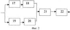
Структура первого, второго, третьего и четвертого блоков вычисления дисперсии проиллюстрирована на фиг. 2. Блок вычисления дисперсии содержит первый и второй квадраторы 17, 20, второе, третье и четвертое интегрирующие звенья соответственно 18, 19 и 22 и вычитатель 21. The structure of the first, second, third, and fourth dispersion calculation units is illustrated in FIG. 2. The dispersion calculation unit contains the first and
Заявляемое устройство должно входить составной частью в общий комплект аппаратно-программных средств мониторинга каналов связи и обеспечивать решение задачи по выделению сигналов факсимильных передач от речи, канального шума и сигналов тональной сигнализации. The inventive device should be part of a common set of hardware and software for monitoring communication channels and provide a solution to the problem of extracting fax signals from speech, channel noise and tonal signals.
Работа устройства основана на оценивании трех информационных статистик, которые обеспечивают устойчивое различение сигналов факсимильных передач от других сигналов, передаваемых по соединительным трактам. The operation of the device is based on the evaluation of three information statistics, which provide a stable distinction between fax signals from other signals transmitted along the connecting paths.
В качестве информационных статистик используются оценка мощности сигнала в рабочей полосе частот, оценка нестабильности огибающей и оценка временной нестабильности значений спектра входного сигнала, которые вычисляется в трех фиксированных точках частотного диапазона канала связи. As information statistics, an estimate of the signal power in the working frequency band, an estimate of the instability of the envelope, and an estimate of the temporal instability of the spectrum of the input signal, which are calculated at three fixed points in the frequency range of the communication channel, are used.
Рассмотрим подробнее работу заявляемого устройства. Анализируемый сигнал с выхода канала связи, пройдя через блок 1 согласования с каналом связи и полосовой фильтр 2, настроенный на рабочую полосу канала связи, поступает одновременно на вход первого блока 3 вычисления абсолютного значения и вход блока вычисления преобразования Фурье. При этом последовательность элементов 3 и 4 обеспечивает получение приближенной оценки уровня сигнала в канале связи. Здесь используется априорная информация о том, что уровень обнаруживаемого сигнала не может быть меньше некоторого фиксированного значения, регламентируемого действующими в телекоммуникационных системах нормами. Входной сигнал уровня меньше порогового считается канальным шумом. Получаемая оценка уровня сигнала подается на вход первого порогового элемента 5, где происходит сравнение полученной величины с граничным значением. Если полученное значение превышает пороговое, то на выходе первого порогового элемента 5 формируется напряжение, соответствующее уровню логической единицы. Далее это значение подается на первый вход логического элемента И 15. Таким образом, осуществляется оценка первого информационного признака для выделения сигналов факсимильного обмена. Consider in more detail the operation of the claimed device. The analyzed signal from the output of the communication channel, passing through the matching unit 1 with the communication channel and the bandpass filter 2 tuned to the working band of the communication channel, is fed simultaneously to the input of the first unit 3 for calculating the absolute value and the input of the Fourier transform calculation unit. The sequence of elements 3 and 4 provides an approximate estimate of the signal level in the communication channel. Here we use a priori information that the level of the detected signal cannot be less than some fixed value regulated by the norms applicable in telecommunication systems. An input signal of a level lower than the threshold is considered channel noise. The resulting signal level estimate is fed to the input of the first threshold element 5, where the obtained value is compared with the boundary value. If the obtained value exceeds the threshold, then at the output of the first threshold element 5, a voltage corresponding to the level of a logical unit is formed. Further, this value is supplied to the first input of AND gate 15. Thus, an evaluation of the first information feature is carried out for extracting fax signals.
Для повышения достоверности различения факсимильного сигнала от сигналов тоновой сигнализации в заявляемом устройстве используется второй информационный признак. Как известно из теории передачи информации, для обеспечения высокой скорости информационного обмена необходимо возможно более полно использовать частотный диапазон канала связи. Данное обстоятельство приводит к тому, что спектр информационного сигнала устройств документальной связи все более приближается к "белому", т.е. происходит достаточно равномерное заполнение частотного диапазона. To increase the reliability of distinguishing a facsimile signal from tone signals in the inventive device, a second information feature is used. As is known from the theory of information transfer, to ensure a high speed of information exchange, it is necessary to use the frequency range of the communication channel as fully as possible. This circumstance leads to the fact that the spectrum of the information signal of documentary communication devices is increasingly approaching the “white” one, i.e. a fairly uniform filling of the frequency range occurs.
Совсем иная картина имеет место применительно к спектрограмме речевого сигнала. Последняя имеет ярко выраженную неравномерность и содержит достаточно продолжительные паузы. A completely different picture takes place with respect to the spectrogram of a speech signal. The latter has a pronounced unevenness and contains quite long pauses.
Еще более значимое отличие данный признак дает при сравнении факсимильного и любого тонального (или двухтонального) сигналов, имеющих стабильную по времени неравномерность спектрограммы. This feature gives an even more significant difference when comparing facsimile and any tonal (or two-tonal) signals with a time-stable spectrogram unevenness.
Таким образом, можно говорить о том, что сущность второго информационного признака основана на различии статистических моделей факсимильного сигнала и других сигналов, которые могут иметь место в канале связи. Thus, we can say that the essence of the second information feature is based on the difference in statistical models of the facsimile signal and other signals that can occur in the communication channel.
Реализация третьего информационного признака производится посредством блоков 6-9. Здесь в блоке 6 преобразования Фурье осуществляется вычисление коэффициентов Фурье, которые затем в последовательном виде передаются в арифметический блок 7, где осуществляется их пересчет в спектрограмму. The implementation of the third information feature is carried out through blocks 6-9. Here, in the block 6 of the Fourier transform, the Fourier coefficients are calculated, which are then sequentially transmitted to the arithmetic block 7, where they are converted into a spectrogram.
В качестве количественной меры неравномерности спектра в заявляемом устройстве выбрана дисперсия спектральных отсчетов. Оценка дисперсии производится в соответствии с выражением:
где
Where
Практически необходимые арифметические операции производятся в блоке 8 вычисления дисперсии (см. фиг. 2). В этом блоке для упрощения технической реализации операция суммирования в выражении (1) заменена интегрированием. Поэтому над сигналом, поступающим на вход блока 8 вычисления дисперсии, выполняется два преобразования: элементы 17 и 18 обеспечивают накопление среднего квадрата, а элементы 19-20 - квадрата среднего значения входного сигнала. Далее в вычитателе 21 производится вычисление разности двух этих величин, а окончательная оценка дисперсии получается на выходе четвертого интегрирующего звена 2. После этого полученное значение дисперсии сравнивается в третьем пороговом элементе 9 с граничной величиной. В случае если граничное значение не превышено, на второй выход логического элемента И 15 подается логическая единица. Practically necessary arithmetic operations are performed in block 8 for calculating the variance (see Fig. 2). In this block, to simplify the technical implementation, the summation operation in expression (1) is replaced by integration. Therefore, on the signal received at the input of the dispersion calculation unit 8, two transformations are performed:
Рассмотрим теперь процедуру оценивания третьего информационного признака, которая производится с помощью блоков 10-14. Как уже упоминалось ранее, третий информационный признак представляет собой оценку временной нестабильности значений спектра входного сигнала, которые вычисляется в трех фиксированных точках частотного диапазона канала связи. Для этого с трех параллельных выходов арифметического блока 7 присутствующие там значения считываются соответственно во второй, третий и четвертый блоки 10,11,12 вычисления дисперсии. Функционирование этих блоков вычисления дисперсии аналогично рассмотренному выше при описании вычисления второго информационного признака. Полученные же на их выходах значения передаются в сумматор 13 для нахождения интегральной оценки нестабильности на всех трех частотах. Далее эта оценка подается на вход третьего порогового элемента 14, где происходит сравнение полученной величины с граничным значением. Если полученное значение превышает пороговое, то на выходе третьего порогового элемента 14 формируется напряжение, соответствующее уровню логической единицы. Затем это значение подается на первый вход логического элемента И 15. Consider now the procedure for evaluating the third information feature, which is performed using blocks 10-14. As mentioned earlier, the third information feature is an estimate of the temporal instability of the values of the spectrum of the input signal, which is calculated at three fixed points in the frequency range of the communication channel. For this, from the three parallel outputs of the arithmetic unit 7, the values present there are read in the second, third, and fourth dispersion calculation blocks 10, 11, 12 respectively. The functioning of these dispersion calculation units is similar to that described above in the description of the calculation of the second information feature. The values obtained at their outputs are transmitted to the adder 13 to find an integral estimate of the instability at all three frequencies. Further, this estimate is fed to the input of the third threshold element 14, where the obtained value is compared with the boundary value. If the obtained value exceeds the threshold, then at the output of the third threshold element 14 a voltage is generated corresponding to the level of a logical unit. Then this value is fed to the first input of the AND gate 15.
При появлении на всех трех входах логического элемента И 15 сигналов, соответствующих логической единице, определенный сигнал подается на управляющий вход блока принятия решения 16. When at all three inputs of the logical element AND 15 the signals corresponding to the logical unit appear, a certain signal is supplied to the control input of the decision block 16.
Реализацию предлагаемого устройства целесообразно проводить с использованием сигнальных микропроцессоров либо с использованием средств вычислительной техники. The implementation of the proposed device, it is advisable to carry out using signal microprocessors or using computer technology.
Источники информации
1. C. Roberge and J.P. Adoul, "Fast on-line speech/voiceband data discrimination for statistical multiplexing of data with telephone conversations" IEEE Transactions Communications, vol. COM-34, pp. 744-751.Aug.l986.Sources of information
1. C. Roberge and JP Adoul, "Fast on-line speech / voiceband data discrimination for statistical multiplexing of data with telephone conversations" IEEE Transactions Communications, vol. COM-34, pp. 744-751.Aug.l986.
2. N. Benvenuto and W. R. Daumer " Classification of voiceband date signals'" Proc. Conference Communications, Atlanta, GA, pp. 1010-1013, Apr. 1990. 2. N. Benvenuto and W. R. Daumer "Classification of voiceband date signals'" Proc. Conference Communications, Atlanta, GA, pp. 1010-1013, Apr. 1990.
Claims (1)
Translated fromRussianPriority Applications (1)
| Application Number | Priority Date | Filing Date | Title |
|---|---|---|---|
| RU2000113767ARU2192667C2 (en) | 2000-05-31 | 2000-05-31 | Facsimile signal identifying device |
Applications Claiming Priority (1)
| Application Number | Priority Date | Filing Date | Title |
|---|---|---|---|
| RU2000113767ARU2192667C2 (en) | 2000-05-31 | 2000-05-31 | Facsimile signal identifying device |
Publications (2)
| Publication Number | Publication Date |
|---|---|
| RU2000113767A RU2000113767A (en) | 2002-04-10 |
| RU2192667C2true RU2192667C2 (en) | 2002-11-10 |
Family
ID=20235524
Family Applications (1)
| Application Number | Title | Priority Date | Filing Date |
|---|---|---|---|
| RU2000113767ARU2192667C2 (en) | 2000-05-31 | 2000-05-31 | Facsimile signal identifying device |
Country Status (1)
| Country | Link |
|---|---|
| RU (1) | RU2192667C2 (en) |
Citations (5)
| Publication number | Priority date | Publication date | Assignee | Title |
|---|---|---|---|---|
| RU2012057C1 (en)* | 1991-07-04 | 1994-04-30 | Эдуард Васильевич Борисов | Device for situation recognition |
| RU2080655C1 (en)* | 1994-03-05 | 1997-05-27 | Институт прикладной астрономии РАН | Device which recognizes information signals |
| US5799010A (en)* | 1995-06-30 | 1998-08-25 | Interdigital Technology Corporation | Code division multiple access (CDMA) communication system |
| US5799111A (en)* | 1991-06-14 | 1998-08-25 | D.V.P. Technologies, Ltd. | Apparatus and methods for smoothing images |
| RU2133501C1 (en)* | 1998-02-04 | 1999-07-20 | Военная академия связи | Method and device to identify classes of signals |
- 2000
- 2000-05-31RURU2000113767Apatent/RU2192667C2/ennot_activeIP Right Cessation
Patent Citations (5)
| Publication number | Priority date | Publication date | Assignee | Title |
|---|---|---|---|---|
| US5799111A (en)* | 1991-06-14 | 1998-08-25 | D.V.P. Technologies, Ltd. | Apparatus and methods for smoothing images |
| RU2012057C1 (en)* | 1991-07-04 | 1994-04-30 | Эдуард Васильевич Борисов | Device for situation recognition |
| RU2080655C1 (en)* | 1994-03-05 | 1997-05-27 | Институт прикладной астрономии РАН | Device which recognizes information signals |
| US5799010A (en)* | 1995-06-30 | 1998-08-25 | Interdigital Technology Corporation | Code division multiple access (CDMA) communication system |
| RU2133501C1 (en)* | 1998-02-04 | 1999-07-20 | Военная академия связи | Method and device to identify classes of signals |
Similar Documents
| Publication | Publication Date | Title |
|---|---|---|
| JP3066213B2 (en) | Control signal detection method | |
| CN111200569B (en) | Broadband signal detection and identification method and device | |
| US20070133787A1 (en) | Method and apparatus for identifying crosstalk sources | |
| Ramirez et al. | A generalization of the magnitude squared coherence spectrum for more than two signals: definition, properties and estimation | |
| US4853958A (en) | LPC-based DTMF receiver for secondary signalling | |
| US5353345A (en) | Method and apparatus for DTMF detection | |
| RU2192667C2 (en) | Facsimile signal identifying device | |
| JPH0678345A (en) | Multiple signal detection and identification system and method | |
| Scholz et al. | Estimation of the quality dimension" directness/frequency content" for the instrumental assessment of speech quality. | |
| Chang | On the filter problem of the power-spectrum analyzer | |
| US7020272B2 (en) | High density signal classifier for media gateways | |
| US4922528A (en) | Circuitry for recognizing two-tone compound signals in telephone installations | |
| US20060008074A1 (en) | Tone detector judging a detection of a predetermined tone signal by comparing a characteristic quantity of the tone signal with characteristic quantities of other signals | |
| CN115981192B (en) | Industrial network-based cooperative control and prejudgment method | |
| KR100839691B1 (en) | Tone Detection Method and System | |
| RU2171549C1 (en) | Device for discriminating acoustic signals in communication channels | |
| US11418422B1 (en) | Received-signal rate detection | |
| CN101635865A (en) | System and method for preventing error detection of dual-tone multi-frequency signals | |
| RU2118067C1 (en) | Device for detection of acoustic signals in communication channels | |
| RU2214051C2 (en) | Device for separating voice-frequency signals in communication channels | |
| Waltermann et al. | Towards a new E-model impairment factor for linear distortion of narrowband and wideband speech transmission | |
| RU2210188C2 (en) | Facility detecting signals of exchange between means of document communication | |
| US4384175A (en) | Tone detection method and arrangement for observing and classifying repetitive status signals | |
| CN119450564B (en) | Dual-mode interphone communication effect evaluation and optimization method based on multi-feature fusion | |
| WO2006040317A1 (en) | Method and apparatus for recognizing a disturbing effect in an information channel |
Legal Events
| Date | Code | Title | Description |
|---|---|---|---|
| MM4A | The patent is invalid due to non-payment of fees | Effective date:20190601 |