RU2184347C2 - Process generating images of internal structure of objects - Google Patents
Process generating images of internal structure of objectsDownload PDFInfo
- Publication number
- RU2184347C2 RU2184347C2RU2000122049ARU2000122049ARU2184347C2RU 2184347 C2RU2184347 C2RU 2184347C2RU 2000122049 ARU2000122049 ARU 2000122049ARU 2000122049 ARU2000122049 ARU 2000122049ARU 2184347 C2RU2184347 C2RU 2184347C2
- Authority
- RU
- Russia
- Prior art keywords
- radiation
- scattered
- resolution
- internal structure
- plane
- Prior art date
Links
- 238000000034methodMethods0.000titleclaimsabstractdescription66
- 230000008569processEffects0.000titleclaimsdescription8
- 230000005855radiationEffects0.000claimsabstractdescription204
- 238000001914filtrationMethods0.000claimsabstractdescription10
- 238000012545processingMethods0.000claimsabstractdescription10
- 230000003595spectral effectEffects0.000claimsdescription43
- 238000000354decomposition reactionMethods0.000claimsdescription20
- 238000005259measurementMethods0.000claimsdescription13
- 238000001514detection methodMethods0.000claimsdescription6
- 230000015572biosynthetic processEffects0.000claims1
- 230000003287optical effectEffects0.000abstractdescription24
- 238000001228spectrumMethods0.000abstractdescription22
- 230000001427coherent effectEffects0.000abstractdescription10
- 238000003325tomographyMethods0.000abstractdescription7
- 230000000694effectsEffects0.000abstractdescription3
- 238000010183spectrum analysisMethods0.000abstract2
- 239000000126substanceSubstances0.000abstract1
- 238000012014optical coherence tomographyMethods0.000description33
- 238000004624confocal microscopyMethods0.000description10
- 239000010755BS 2869 Class GSubstances0.000description8
- 238000012552reviewMethods0.000description7
- 230000004044responseEffects0.000description6
- 238000005305interferometryMethods0.000description4
- 238000002577ophthalmoscopyMethods0.000description4
- 230000010355oscillationEffects0.000description4
- 210000001525retinaAnatomy0.000description4
- 230000009466transformationEffects0.000description4
- 238000006243chemical reactionMethods0.000description3
- 238000005516engineering processMethods0.000description3
- 230000002441reversible effectEffects0.000description3
- 238000011896sensitive detectionMethods0.000description3
- 230000035945sensitivityEffects0.000description3
- 238000010586diagramMethods0.000description2
- 239000006185dispersionSubstances0.000description2
- 238000001839endoscopyMethods0.000description2
- 238000005286illuminationMethods0.000description2
- 230000002452interceptive effectEffects0.000description2
- 239000000203mixtureSubstances0.000description2
- 238000001579optical reflectometryMethods0.000description2
- 239000007787solidSubstances0.000description2
- 238000000844transformationMethods0.000description2
- 230000009471actionEffects0.000description1
- 238000000149argon plasma sinteringMethods0.000description1
- 230000005540biological transmissionEffects0.000description1
- 230000008859changeEffects0.000description1
- 238000004891communicationMethods0.000description1
- 239000000470constituentSubstances0.000description1
- 230000008878couplingEffects0.000description1
- 238000010168coupling processMethods0.000description1
- 238000005859coupling reactionMethods0.000description1
- 230000003111delayed effectEffects0.000description1
- 230000023077detection of light stimulusEffects0.000description1
- 238000011161developmentMethods0.000description1
- 238000006073displacement reactionMethods0.000description1
- 230000008030eliminationEffects0.000description1
- 238000003379elimination reactionMethods0.000description1
- 238000000295emission spectrumMethods0.000description1
- 239000000835fiberSubstances0.000description1
- 238000009472formulationMethods0.000description1
- 230000036039immunityEffects0.000description1
- 230000006872improvementEffects0.000description1
- 238000001727in vivoMethods0.000description1
- 230000010354integrationEffects0.000description1
- 239000000463materialSubstances0.000description1
- 238000000691measurement methodMethods0.000description1
- 238000000386microscopyMethods0.000description1
- 238000012544monitoring processMethods0.000description1
- 239000013307optical fiberSubstances0.000description1
- 230000005693optoelectronicsEffects0.000description1
- 230000010363phase shiftEffects0.000description1
- 238000012827research and developmentMethods0.000description1
- 238000004621scanning probe microscopyMethods0.000description1
- 230000001360synchronised effectEffects0.000description1
- 230000002123temporal effectEffects0.000description1
Images


Landscapes
- Investigating Or Analysing Materials By Optical Means (AREA)
Abstract
Description
Translated fromRussianИзобретение относится к оптическому приборостроению, в частности к технике получения изображений внутренней структуры трехмерных объектов (оптической томографии) с предельно высоким пространственным разрешением, определяемым волновыми свойствами излучения. The invention relates to optical instrumentation, in particular to a technique for obtaining images of the internal structure of three-dimensional objects (optical tomography) with extremely high spatial resolution, determined by the wave properties of radiation.
Преимущественными областями применения изобретения является биологическая и медицинская микроскопия, офтальмоскопия, ретиноскопия и эндоскопия. Preferred fields of application of the invention are biological and medical microscopy, ophthalmoscopy, retinoscopy and endoscopy.
Уровень техники
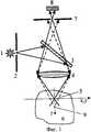
Для развития техники томографии с разрешением, определяемым волновыми свойствами излучения, основополагающее значение имеет способ конфокальной сканирующей микроскопии (Патент US 03013467, публ. 1961). Принцип конфокальной микроскопии иллюстрируется фиг.1. Излучение источника света 1 фильтруют точечной диафрагмой 2 и получают источник дифракционно-ограниченного излучения (Под точечной диафрагмой имеется в виду диафрагма, отверстие которой не превышает размер дифракционного пятна фильтруемого излучения). Наиболее часто источником излучения дифракционно-ограниченного излучения фактически является лазер. Излучение направляют на светоделитель 3. Излучение, отраженное от светоделителя 3, фокусируют объективом 4 в точке 5 внутри трехмерного объекта 6. Вторичное излучение, испускаемое объектом, направляют на диафрагму 7 с помощью объектива 4, при этом центр диафрагмы совмещают с изображением точки фокусировки 4. Вторичное излучение, испускаемое из точки фокусировки 5, проходит сквозь отверстие диафрагмы 7 и попадает на фотоприемник 8. Излучение, испускаемое точечными вторичными излучателями объекта, расположенными на некотором расстоянии от точки фокусировки (например, излучение из точки 9), в той или иной степени задерживается диафрагмой 6. В результате на фотоприемник 8 попадает, главным образом, вторичное излучение объекта, испускаемое из практически ограниченной области трехмерного пространства, с центром в точке фокусировки 4.State of the art
For the development of tomography technique with a resolution determined by the wave properties of radiation, the method of confocal scanning microscopy is of fundamental importance (Patent US 03013467, publ. 1961). The principle of confocal microscopy is illustrated in figure 1. The radiation of the
Размер этой области в поперечном направлении (х, у на фиг.1) равен
dxy≈0.9λ/2A, (1)
а ее размер в продольном направлении (z на фиг.1) равен
dz≈1.8λ/(A2). (2)
Здесь λ- длина волны излучения,
А - численная апертура объектива микроскопа 4.The size of this region in the transverse direction (x, y in FIG. 1) is equal to
dxy ≈0.9λ / 2A, (1)
and its size in the longitudinal direction (z in figure 1) is equal to
dz ≈1.8λ / (A2 ). (2)
Here λ is the radiation wavelength,
A is the numerical aperture of the
(Например, Handbook of Biological Confocal Microscopy, Ed. J.B. Pawley, New York, Plenum, 1995). (E.g. Handbook of Biological Confocal Microscopy, Ed. J. B. Pawley, New York, Plenum, 1995).
Точку фокусировки 5 перемещают в трехмерном пространстве объекта (например, при движении объекта) и детектируют вторичное излучение объекта фотоприемником 8. Т.к. интенсивность вторичных излучателей зависит от плотности материала объекта, то в результате сканирования получают изображение трехмерной структуры объекта. Это изображение характеризуется поперечным разрешением dxy и продольным разрешением dz.The
В частности, конфокальный микроскоп, в котором используется гетеродинная регистрация излучения, рассеянного объектом, описан в патенте US 3780217, кл. H 04 N 1/26; H 04 N 7/18, публ. 1973. Использование конфокальной фильтрации излучения, рассеянного объектом в сочетании с гетеродинной регистрацией излучения, является существенным признаком заявляемого изобретения. In particular, a confocal microscope that uses a heterodyne registration of radiation scattered by an object is described in US Pat. No. 3,780,217, class. H 04
Одним из факторов, ограничивающих возможности конфокальной микроскопии, является то, что, согласно формуле (2) при малых значениях численной апертуры А продольное разрешение, пропорциональное 1/(А2), оказывается существенно хуже поперечного. Вместе с тем малые значения численной апертуры неизбежны в задачах получения изображения на большой глубине объекта, а также характерны для таких важных медицинских применений, как эндоскопия и офтальмоскопия.One of the factors limiting the possibilities of confocal microscopy is that, according to formula (2), for small values of the numerical aperture A, the longitudinal resolution proportional to 1 / (A2 ) is significantly worse than the transverse one. At the same time, small values of the numerical aperture are inevitable in the tasks of obtaining images at a great depth of the object, and are also characteristic of such important medical applications as endoscopy and ophthalmoscopy.
Устранение этого недостатка при улучшении продольного разрешения реализовано при использовании методов низкокогерентной интерферометрии в сочетании с конфокальной микроскопией. Соответствующий способ получения изображений внутренней структуры объектов был назван оптической когерентной томографией (ОКТ). The elimination of this drawback with the improvement of the longitudinal resolution was realized using the methods of low coherent interferometry in combination with confocal microscopy. The corresponding method for obtaining images of the internal structure of objects was called optical coherence tomography (OCT).
В способе ОКТ используется немонохроматическое излучение с широким спектром (например, 50 нм) и, следовательно, с низкой временной когерентностью. При двухлучевой интерференции немонохроматического излучения диапазон разности хода, в пределах которого возможна интерференция, ограничен. Этот диапазон определяется временем когерентности излучения и он тем уже, чем шире спектр излучения (чем ниже его время когерентности). Указанное свойство использовано для получения высокого продольного разрешения при наблюдении рассеивающих свет объектов (патент ЕР 0659383, кл. А 61 В 3/12, публ. 1995; патент US 5459570, кл. G 01 D 9/02. публ. 1995; патент WO 9838907, кл. А 61 В 5/00, публ. 1998; патент WO 9732182, кл. G 01 B 11/12; G 01 B 9/02; публ. 1997; патент US 5321501, кл. G 01 B 9/02, публ. 1994; D. Huang и др. "Optical Coherence Tomography", Science, Vol. 254, pp. 1178-1181, 1991; J.M. Schmitt, "Optical Coherence Tomography (OCT): A. Review", IEEE Journal of Selected Topics in Quantum Electronics, Vol. 5, No 4, p. 1205-1215, 1999; Optical Coherence Tomograph, описание прибора, выпускаемого фирмой Zeiss-Humphrey. The OCT method uses non-monochromatic radiation with a wide spectrum (for example, 50 nm) and, therefore, with low temporal coherence. In case of two-beam interference of nonmonochromatic radiation, the range of the path difference within which interference is possible is limited. This range is determined by the coherence time of the radiation and the narrower it is, the wider the spectrum of the radiation (the lower its coherence time). This property was used to obtain high longitudinal resolution when observing light-scattering objects (patent EP 0659383, class A 61 3/12, publ. 1995; patent US 5459570, class G 01
Указанный способ иллюстрируется фиг.2. Излучение точечного источника немонохроматического излучения 1 (фактически таким источником наиболее часто является суперлюминесцентный диод, испускающий дифракционно-ограниченное излучение с достаточно широким спектром) расщепляют светоделителем 3 на опорное излучение 10 и объектное излучение 11. Объектное излучение фокусируют в точке 5 внутри объекта 6. При этом в объекте возникают источники вторичного рассеянного излучения. Излучение, рассеянное объектом в обратном направлении, направляют на диафрагму 7. Опорное излучение отражается от отражателя 12, светоделителя 3 и его также фокусируют на диафрагму 7. Таким образом, в данном примере реализуется интерферометр Майкельсона, в котором в качестве одного из отражателей выступает исследуемый объект 6. Опорное излучение и рассеянное излучение, испускаемое вторичными источниками объекта, интерферируют в плоскости диафрагмы 7. При этом интерференция возможна только для тех вторичных излучателей, которые расположены в пределах плоского слоя 13, перпендикулярного оптической оси объектива (оси z). Положение серединной плоскости этого слоя отвечает равенству двух оптических путей (а) от источника до указанной плоскости и от указанной плоскости до диафрагмы 7 и (б) от источника до отражателя 12 и далее до диафрагмы 7. Толщина слоя 13 dc определяет продольное разрешение метода ОКТ. Эта толщина равна половине времени когерентности, умноженной на скорость света в среде. В свою очередь, время когерентности равно обратной величине полосы частот излучения. Выражение, описывающее продольное разрешение метода ОКТ, имеет вид:
dc≈0,44λ2/Δλ. (3)
Здесь λ- средняя длина волны источника излучения,
Δλ- ширина спектра источника излучения в шкале длин волн
(например, J.M. Schmitt, "Optical Coherence Tomography (OCT): A Review", IEEE Journal of Selected Topics in Quantum Electronics, Vol. 5, 4, p. 1205-1215, 1999).The specified method is illustrated in figure 2. The radiation from a point source of nonmonochromatic radiation 1 (in fact, the most commonly used source is a superluminescent diode emitting diffraction-limited radiation with a fairly wide spectrum) is split by a
dc ≈0.44λ2 / Δλ. (3)
Here λ is the average wavelength of the radiation source,
Δλ is the width of the spectrum of the radiation source in the wavelength scale
(e.g. JM Schmitt, "Optical Coherence Tomography (OCT): A Review", IEEE Journal of Selected Topics in Quantum Electronics, Vol. 5, 4, p. 1205-1215, 1999).
Величина dc может быть существенно меньше разрешения dz в способе конфокальной микроскопии, определяемого формулой (2).The value of dc may be significantly less than the resolution of dz in the method of confocal microscopy defined by formula (2).
Кроме излучения, испускаемого слоем 13, существует рассеянное излучение, исходящее из других точек объекта и также попадающее на фотоприемник 8. Чтобы селектировать излучение слоя 13 (способное к интерференции с опорным излучением) от излучения, рассеянного другими слоями объекта (не способного к интерференции с опорным излучением), отражатель 12 непрерывно перемещают в продольном направлении. При этом возникает доплеровский сдвиг частот отраженного опорного излучения. При интерференции опорного излучения и рассеянного излучения, испускаемого слоем 13, возникают биения интенсивности на частоте доплеровского сдвига. Эти биения детектируются фотоприемником 8. По мере движения отражателя 12 слой интерферирующих вторичных излучателей 13 также перемещается внутри объекта. Таким образом, производят сканирование объекта в продольном направлении и одновременно регистрируют его внутреннюю структуру в виде зависимости интенсивности биений от координаты z положения слоя 13с разрешением dc, определяемым формулой (3).In addition to the radiation emitted by
Чтобы получить изображение трехмерной структуры объекта, точку фокусировки перемещают, кроме того, в поперечных направлениях (x и y). При этом поперечное разрешение определяется формулой (1). In order to obtain an image of the three-dimensional structure of the object, the focus point is also moved in the transverse directions (x and y). In this case, the transverse resolution is determined by formula (1).
Сопоставление оптической когерентной томографии с конфокальной микроскопией, важное для обоснования преимуществ заявляемого изобретения, показано на фиг.3 и 4. На этих фигурах изображена более детальная картина фокусировки излучения внутри объекта с учетом волновых свойств излучения. Структура излучения вблизи точки фокуса 5 объектива 4 имеет вид перетяжки. Заштрихованный эллипс 14 на фиг. 3 изображает область пространства, определяющую пространственное разрешение при конфокальном сканировании. На фиг.4 заштрихованная область 15 определяет пространственное разрешение способа ОКТ. Как можно видеть из сопоставления фиг.3 и фиг.4, применение ОКТ позволяет существенно улучшить продольное разрешение по сравнению с конфокальным методом. A comparison of optical coherence tomography with confocal microscopy, which is important to justify the advantages of the claimed invention, is shown in FIGS. 3 and 4. These figures show a more detailed picture of the focusing of radiation inside an object, taking into account the wave properties of the radiation. The radiation structure near the
Описанные способы ОКТ обладают тем недостатком, что в них используется механическое сканирование отражателя интерферометра. Это ограничивает быстроту измерения либо приводит к очень сложным конструкциям движущегося отражателя. The described OCT methods have the disadvantage that they use mechanical scanning of the reflector of the interferometer. This limits the speed of measurement or leads to very complex designs of a moving reflector.
Другой важный недостаток заключается в том, что производительность этих способов существенно ниже, чем принципиально возможная. Это связано с тем, что из всего, в принципе, доступного для измерения рассеянного излучения, испускаемого из объема, ограниченного телом конфокального разрешения 14 (фиг. 3), используется только излучение, испускаемое из сравнительно малой области 15 фиг.4. Эти недостатки устранены в заявляемом изобретении. Another important drawback is that the performance of these methods is significantly lower than the fundamentally possible. This is due to the fact that of all, in principle, available for measuring the scattered radiation emitted from the volume limited by the confocal resolution body 14 (Fig. 3), only the radiation emitted from the relatively
В другом способе оптической когерентной томографии (патент WO 9835203, кл. G 01 B 9/02; H 01 S 3/085, публ. 1998; патент US 5956355, кл. H 01 S 3/10, публ. 1999) вместо немонохроматического источника используется источник монохроматического излучения, частота излучения которого быстро перестраивается в заданном частотном диапазоне. Фотоприемник регистрирует зависимость сигнала биений от частоты излучения источника. Результаты детектирования сигнала интерференции в зависимости от частоты преобразуются в зависимость отраженного сигнала от продольной координаты z в исследуемом объекте с помощью преобразования Фурье. Недостатком способа является сложность реализации лазерного устройства с достаточно быстрым сканированием частоты в достаточно широком частотном интервале. Фактически в реализациях этого способа для перестройки частоты используется механическое сканирование зеркала, помещаемого в резонатор лазера (S.R. Chinn, E.A. Swanson, J.G. Fujimoto, "Optical coherence tomography using a frequency-tunable optical source". Optics Letters, Vol. 22, 5, pp. 340-342, 1997). В заявляемом изобретении также используется спектральное разложение, но без сканирования частоты. In another optical coherence tomography method (patent WO 9835203, class G 01
Известен также способ томографии (T. Mitsui, "Dynamic range of optical reflectometry with spectral interferometry", Japanese Journal of Applied Physics, Vol. 38, Part. 1, 10, pp. 6133-6137, 1999), в котором используют спектральное разложение суммы опорного и рассеянного излучения. В результате спектрального разложения получают распределение интенсивности суммы опорного и рассеянного излучения по спектру (спектральную голограмму). Это распределение содержит полосы интерференции. Спектральную голограмму регистрируют панорамным приемником методом прямого детектирования. Затем голограмму расшифровывают известными методами. Недостатком метода является низкая чувствительность прямого детектирования слабого полезного сигнала рассеяния на фоне существенных паразитных засветок. В заявляемом изобретении, также использующем пространственное спектральное разложение, этот недостаток устранен. Also known is a tomography method (T. Mitsui, "Dynamic range of optical reflectometry with spectral interferometry", Japanese Journal of Applied Physics, Vol. 38, Part. 1, 10, pp. 6133-6137, 1999), which uses spectral decomposition the sum of the reference and scattered radiation. As a result of spectral decomposition, the intensity distribution of the sum of the reference and scattered radiation over the spectrum (spectral hologram) is obtained. This distribution contains interference bands. The spectral hologram is recorded with a panoramic receiver by direct detection. Then the hologram is decrypted by known methods. The disadvantage of this method is the low sensitivity of direct detection of a weak useful scattering signal against the background of significant spurious illumination. In the claimed invention, also using spatial spectral decomposition, this disadvantage is eliminated.
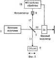
Наиболее близким аналогом (прототипом) заявляемого изобретения являются способ и устройство, описанные в патенте WO 9961865, кл. G 01 B 9/02, публ. 1999. Целью этого изобретения является получение изображений поперечного сечения объектов при продольном разрешении, существенно лучшем, чем конфокальное продольное разрешение. The closest analogue (prototype) of the claimed invention are the method and device described in patent WO 9961865, class. G 01
Существенные признаки указанного изобретения иллюстрируются фиг.5. Источник излучения 1 является дифракционно-ограниченным (например, лазером) и немонохроматическим, обладающим некоторой шириной спектра Δλ. Излучение источника расщепляют светоделителем 3 на опорное излучение 10 и объектное излучение 11. Опорное излучение пропускают через фазовый модулятор 16, в результате чего все его частотные составляющие приобретают одинаковый частотный сдвиг. Объектное излучение фокусируют в точке внутри объекта 6. Излучение, рассеянное объектом, и опорное излучение пространственно совмещают в единое суммарное излучение 17, которое падает на фотодетектор 8. Как и в методе конфокальной микроскопии (см. фиг. 1), рассеянное излучение пространственно фильтруют диафрагмой на плоскости, сопряженной с плоскостью фокусировки объектного излучения. С помощью фотодетектора 8 и устройства обработки 18 регистрируют сигнал биений опорного и объектного излучения, вызванный сдвигом частот опорного излучения и интерференцией опорного и рассеянного излучения. В интерференции участвует только рассеянное излучение, испускаемое тонким слоем объекта, как это показано на фиг.2. Положение этого слоя определяется условиями равенства длин путей в двух плечах интерферометра, а его толщина dc определяется формулой (3). Величину dc выбирают существенно меньшей, чем продольное конфокальное разрешение dz. Поэтому осуществляется ситуация, при которой поперечное разрешение определяется дифракцией согласно формуле (1), а продольное разрешение - формулой (3). В результате реализуется тело объемного разрешения 15, изображенное на фиг.4.The essential features of this invention are illustrated in FIG. The
При сканировании точки фокусировки объектного излучения в плоскости фокусировки х, у и одновременной регистрации сигнала биений получают изображение поперечного сечения объекта с продольным разрешением, определяемым формулой (3). При смещении плоскости фокусировки в продольном направлении возможно получение изображений любых других поперечных сечений объекта с тем же продольным разрешением. When scanning the focus point of the object radiation in the focusing plane x, y and simultaneously registering the beat signal, an image of the cross section of the object with a longitudinal resolution determined by formula (3) is obtained. When the focus plane is shifted in the longitudinal direction, it is possible to obtain images of any other cross-sections of the object with the same longitudinal resolution.
Рассмотренный прототип заявляемого изобретения обладает тем недостатком, что его производительность существенно ниже, чем принципиально возможная. Это связано с тем, что из всего, в принципе, доступного для измерения рассеянного излучения, испускаемого из объема, ограниченного телом конфокального разрешения 14 (фиг.5), используется только излучение, испускаемое из малой области 15 фиг.5. The considered prototype of the claimed invention has the disadvantage that its performance is significantly lower than possible. This is due to the fact that of all, in principle, available for measuring the scattered radiation emitted from the volume limited by the confocal resolution body 14 (Fig. 5), only the radiation emitted from the
Сущность изобретения
Основная задача изобретения заключается в повышении производительности регистрации изображений внутренней структуры объектов.SUMMARY OF THE INVENTION
The main objective of the invention is to increase the performance of recording images of the internal structure of objects.
Способ, обеспечивающий решение указанной технической задачи, заключается в следующем (см. также фиг.6, на которой показан пример функциональной схемы). A method that provides a solution to the specified technical problem is as follows (see also Fig.6, which shows an example of a functional diagram).
Дифракционно-ограниченное немонохроматическое излучение 19, испускаемое источником 1, расщепляют на опорное 10 и объектное 11 излучения (в данном примере с помощью светоделителя 3). Пучок объектного излучения с помощью объектива 4 фокусируют в точке 5, расположенной внутри исследуемого трехмерного объекта 6. При этом падающее объектное излучение рассеивается на неоднородностях объекта. Излучение, рассеянное объектом, можно описать как излучение большого числа вторичных источников излучения, принадлежащих объекту. Вторичные источники возникают в общем случае во всей области объекта, освещаемой объектным излучением. Часть излучения 20, рассеянного объектом и попадающего в апертуру объектива 4, с помощью этого объектива направляют в обратном ходе лучей на плоскость 21, сопряженную плоскости фокусировки объектного излучения 22. С целью ограничения области объекта, из которой возможно наблюдение рассеянного излучения, рассеянное излучение, падающее на плоскость 21, пространственно фильтруют с помощью точечной диафрагмы 7 (Возможны также и другие способы пространственной фильтрации, например, пропускание излучения по одномодовому оптическому волокну). С помощью пространственной фильтрации осуществляют селекцию рассеянного излучения (ср. с фиг.1) и тем самым ограничивают область, из которой наблюдается рассеянное излучение, областью конфокального разрешения, изображенной на фиг.3. Продольный и поперечный размеры этой области определяются формулами (1) и (2). The diffraction-limited non-monochromatic radiation 19 emitted by the
С помощью фазового модулятора вводят сдвиг частоты в опорное, объектное или рассеянное излучение. В данном примере вводят сдвиг частоты в опорное излучение 10 с помощью фазового модулятора 16. Затем опорное излучение 10 пространственно объединяют (например, с помощью светоделителя 3) с рассеянным излучением 20 и получают суммарное излучение 17. На примере, показанном на фиг.6, опорное излучение 10 пространственно фильтруют, как и рассеянное излучение, однако это необязательно и объединение опорного и рассеянного излучения в суммарное излучение может быть выполнено после пространственной фильтрации рассеянного излучения. Using a phase modulator, a frequency shift is introduced into the reference, object, or scattered radiation. In this example, a frequency shift is introduced into the
При интерференции опорного и рассеянного излучения возникают световые биения, создающие осцилляции интенсивности суммарного излучения на частоте, равной введенному частотному сдвигу. Детектирование световых биений позволяет с высокой чувствительностью и помехоустойчивостью регистрировать излучение, рассеянное объектом. During interference of the reference and scattered radiation, light beats appear, which create oscillations in the intensity of the total radiation at a frequency equal to the introduced frequency shift. The detection of light beats allows with high sensitivity and noise immunity to register radiation scattered by the object.
Чтобы определить зависимость излучения, рассеянного объектом от координат х, у, на плоскости 22 выполняют позиционное сканирование точки фокусировки объектного пучка в плоскости фокусировки, повторяя для каждой позиции детектирование переменной составляющей интенсивности суммарного излучения. To determine the dependence of the radiation scattered by the object on the x, y coordinates, on the plane 22, a positional scan of the focus point of the object beam in the focus plane is performed, repeating for each position the detection of the variable component of the intensity of the total radiation.
Приведенные признаки относились к прототипу. Существенные отличия заявляемого изобретения от прототипа заключаются в следующем. These signs related to the prototype. Significant differences of the claimed invention from the prototype are as follows.
Суммарное излучение подвергают пространственному спектральному разложению, которое может быть выполнено, например, с помощью прибора типа спектрографа 23. В результате спектрального разложения формируется изображение спектра суммарного излучения на плоскости 24. При реальном пространственном спектральном разложении величина частотного разрешения спектрального прибора ограничена. Поэтому в каждой точке изображения спектра содержится некоторый диапазон частот, равный частотному разрешению спектрального прибора. Приблизительно такой же диапазон частот содержится в участке изображения спектра, ширина которого равна обратной дисперсии спектрального разложения, умноженной на частотное разрешение. Таким образом, получаемое изображение спектра состоит из независимых спектральных компонент, каждая из которых обладает шириной полосы частот, определяемой частотным разрешением прибора. The total radiation is subjected to spatial spectral decomposition, which can be performed, for example, using a device such as
Как отмечалось, суммарное излучение формируется в результате интерференции опорного и рассеянного излучений. Это относится также и к каждой независимой спектральной компоненте суммарного излучения, выделяемой при спектральном разложении. Поскольку в опорное излучение введен сдвиг частоты, то интерференция оказывается нестационарной. Поэтому каждая независимая спектральная компонента содержит осцилляции интенсивности на частоте, равной сдвигу частоты, введенному фазовым модулятором. As noted, the total radiation is formed as a result of interference of the reference and scattered radiation. This also applies to each independent spectral component of the total radiation emitted during spectral decomposition. Since a frequency shift is introduced into the reference radiation, the interference is unsteady. Therefore, each independent spectral component contains intensity oscillations at a frequency equal to the frequency shift introduced by the phase modulator.
Условием получения таких осцилляций является превышение полосы частот, содержащейся в отдельной спектральной компоненте над величиной сдвига частоты, вводимого с помощью фазового модулятора 16. Это условие легко выполняется для всех представляющих интерес случаев. Частотное разрешение прибора не требуется лучшим, чем обратная величина времени пробега светом области конфокального разрешения dz. В шкале длин волн эта величина определяется формулой (2). Например, при dz=2 мм частотное разрешение составляет 1012 Гц. С другой стороны, сдвиг частоты, который может быть введен в излучение при фазовой модуляции, не превышает 100 МГц. Таким образом, указанное условие соблюдается, и каждый элемент спектрального разрешения содержит световые биения.The condition for obtaining such oscillations is the excess of the frequency band contained in a separate spectral component over the magnitude of the frequency shift introduced by the
Амплитуду и фазу переменной составляющей интенсивности суммарного излучения измеряют одновременно для всех независимых спектральных компонент, выделенных при спектральном разложении. Это может быть выполнено, например, с помощью линейки фотоприемников 25. Фазу измеряют относительно фазы переменного электрического сигнала, использованного для фазовой модуляции излучения. Таким образом осуществляют гетеродинное детектирование рассеянного излучения для каждой его спектральной компоненты. The amplitude and phase of the variable component of the intensity of the total radiation are measured simultaneously for all independent spectral components isolated during spectral decomposition. This can be done, for example, using a line of photodetectors 25. The phase is measured relative to the phase of the alternating electrical signal used to phase modulate the radiation. Thus, heterodyne detection of scattered radiation for each of its spectral components is carried out.
Как известно (например, Н. Д. Устинов, И.Н. Матвеев, В.В. Протопопов, "Методы обработки оптических полей в лазерной локации", Москва, 1985), амплитуда переменного электрического сигнала, получаемого при гетеродинировании рассеянного (отраженного) света, пропорциональна амплитудному коэффициенту рассеяния, умноженному на амплитуду падающего света, а фаза этого сигнала соответствует фазовому сдвигу при рассеянии. При гетеродинировании всех спектральных компонент рассеянного излучения получают зависимость амплитуды и фазы рассеянного излучения от частоты падающего излучения. As is known (for example, ND Ustinov, IN Matveev, VV Protopopov, "Methods of processing optical fields in a laser location", Moscow, 1985), the amplitude of an alternating electric signal obtained by heterodyning scattered (reflected) light is proportional to the amplitude scattering coefficient multiplied by the amplitude of the incident light, and the phase of this signal corresponds to the phase shift during scattering. When heterodyning all spectral components of the scattered radiation, the dependence of the amplitude and phase of the scattered radiation on the frequency of the incident radiation is obtained.
Для каждой частоты амплитуду рассеянного излучения нормируют на корень квадратный из интенсивности (т. е. амплитуды) опорного излучения на этой частоте. При этом получают амплитудно-фазовую (комплексную) частотную характеристику рассеяния, не зависящую от спектра источника излучения. For each frequency, the amplitude of the scattered radiation is normalized to the square root of the intensity (i.e., amplitude) of the reference radiation at that frequency. In this case, the amplitude-phase (complex) frequency response of the scattering is obtained, independent of the spectrum of the radiation source.
Последующую обработку результатов измерений основывают на теории линейного преобразования сигналов (например, А. Папулис, Теория систем и преобразований в оптике, Москва, 1971, стр. 54-57). Полученная амплитудно-фазовая характеристика рассеяния представляет собой комплексную частотную характеристику линейного преобразования входного сигнала. В данном случае входным сигналом является опорное излучение, а линейным преобразованием - процесс рассеяния излучения. Следуя теории линейного преобразования сигналов, выполняют с помощью устройства обработки 18 преобразование Фурье измеренной частотной характеристики и получают в результате импульсную характеристику рассеяния:
h(t) = ∫H(ν-ν0)exp[-i2π(ν-ν0)t]d(ν-ν0). (4)
где ν - частота излучения,
ν0- центральная частота излучения,
t - время,
i - мнимая единица,
H(ν-ν0)- комплексная частотная характеристика рассеяния
h(t) - импульсная характеристика рассеяния или амплитудная форма импульса рассеянного излучения, возникающего после освещения объекта импульсом, длительность которого существенно меньше, чем длительность импульса рассеяния,
интегрирование производят по всему измеряемому спектру.Subsequent processing of measurement results is based on the theory of linear signal conversion (for example, A. Papulis, Theory of Systems and Transformations in Optics, Moscow, 1971, pp. 54-57). The obtained amplitude-phase scattering characteristic is a complex frequency response of a linear transformation of the input signal. In this case, the input signal is the reference radiation, and a linear transformation is the process of radiation scattering. Following the theory of linear signal conversion, Fourier transform of the measured frequency response is performed using
h (t) = ∫H (ν-ν0 ) exp [-i2π (ν-ν0 ) t] d (ν-ν0 ). (4)
where ν is the radiation frequency,
ν0 is the central radiation frequency,
t is the time
i is the imaginary unit
H (ν-ν0 ) is the complex frequency response of scattering
h (t) is the impulse response of the scattering or the amplitude shape of the impulse of the scattered radiation that occurs after the object is illuminated by a pulse whose duration is substantially less than the duration of the scattering pulse,
integration is carried out over the entire measured spectrum.
Далее вычисляют импульсную характеристику рассеяния в единицах интенсивности:
I(t) = |h(t)|2. (5)
Здесь I(t) - зависимость интенсивности рассеянного излучения от времени после освещения объекта достаточно коротким импульсом.Then calculate the impulse response of the scattering in units of intensity:
I (t) = | h (t) |2 . (5)
Here I (t) is the dependence of the intensity of the scattered radiation on time after illumination of the object with a sufficiently short pulse.
Применение импульсной характеристики рассеяния I(t) для получения одномерного изображения внутренней структуры объекта иллюстрируется фиг.7. Короткий импульс излучения I0(t) падает на рассеивающий объект 6, толщина которого существенно больше геометрической протяженности импульса. В процессе распространения этого импульса внутри объекта возникают и исчезают вторичные излучатели, соответствующие разным значением координаты z. При регистрации интенсивности обратнорассеянного излучения в некоторой плоскости 26 сигналы, соответствующие разным координатам z, приходят с запаздыванием
t = 2z/ν,
где ν - скорость света в среде.The application of the impulse scattering characteristic I (t) to obtain a one-dimensional image of the internal structure of an object is illustrated in Fig. 7. A short radiation pulse I0 (t) falls on the
t = 2z / ν,
where ν is the speed of light in the medium.
Интенсивность рассеяния, отвечающего координате z, пропорциональна плотности рассеивающих центров P(z). Следовательно, зависимость плотности рассеивающих центров P(z) от координаты z есть:
P(z) = const•I(2z/ν). (6)
Распределение P(z) можно назвать одномерным продольным изображением структуры объекта.The scattering intensity corresponding to the z coordinate is proportional to the density of scattering centers P (z). Therefore, the dependence of the density of scattering centers P (z) on the z coordinate is:
P (z) = const • I (2z / ν). (6)
The distribution P (z) can be called a one-dimensional longitudinal image of the structure of the object.
Описанной процесс соответствует хорошо известному методу импульсной локации, позволяющему определить распределение рассеивающих центров вдоль направления луча по форме импульса рассеяния. Однако с учетом необходимого в данных применениях временного разрешения (до 10-13 с) использование метода импульсной оптической локации не имеет смысла. Заявляемое изобретение позволяет получить результат, полностью эквивалентный результату импульсной локации с помощью стационарных гетеродинных спектральных измерений.The described process corresponds to the well-known method of pulsed location, which allows to determine the distribution of scattering centers along the direction of the beam according to the shape of the scattering pulse. However, taking into account the time resolution required in these applications (up to 10-13 s), the use of the pulsed optical location method does not make sense. The claimed invention allows to obtain a result completely equivalent to the result of a pulsed location using stationary heterodyne spectral measurements.
Важным условием реализации заявляемого способа является правильный выбор необходимого числа независимых элементов спектрального разложения. Величина продольного разрешения dc, как и в других описанных когерентных методах, определяется формулой (3). С другой стороны, при фиксированном положении точки фокусировки объектного излучения максимально доступный для наблюдения диапазон глубины изображения объекта dz определяется формулой (2), определяющей конфокальное разрешение. Отношение dz/dc дает число N независимых элементов продольного разрешения:
N = dz/dc (7)
Из теории преобразований Фурье (например, А. Папулис, Теория систем и преобразований в оптике, Москва, 1971) известно, что, если сложный сигнал ограничен по времени и по спектру, то число независимых элементов во временной зависимости практически равно числу независимых элементов в спектре. Таким образом, число независимых спектральных элементов при пространственном спектральном разложении суммарного излучения должно быть не меньше ожидаемого числа элементов продольного разрешения объекта N. Например, конфокальное продольное разрешение может составлять 300 мкм, а продольное разрешение, связанное с применением низкокогерентной интерферометрии - 10 мкм. В этом случае число независимых элементов спектрального разложения (и, соответственно, независимых фотодетекторов 24 фиг.6) должно быть не менее 30.An important condition for the implementation of the proposed method is the correct choice of the required number of independent elements of spectral decomposition. The magnitude of the longitudinal resolution dc , as in the other described coherent methods, is determined by formula (3). On the other hand, with a fixed position of the focus point of the object radiation, the maximum accessible for observation range of the image depth of the object dz is determined by formula (2), which determines the confocal resolution. The ratio dz / dc gives the number N of independent elements of longitudinal resolution:
N = dz / dc (7)
From the theory of Fourier transforms (for example, A. Papulis, Theory of Systems and Transformations in Optics, Moscow, 1971) it is known that if a complex signal is limited in time and spectrum, then the number of independent elements in time dependence is almost equal to the number of independent elements in the spectrum . Thus, the number of independent spectral elements in the spatial spectral decomposition of the total radiation should not be less than the expected number of elements of the longitudinal resolution of the object N. For example, the confocal longitudinal resolution can be 300 μm, and the longitudinal resolution associated with the use of low coherent interferometry can be 10 μm. In this case, the number of independent elements of spectral decomposition (and, accordingly,
Таким образом, при неподвижном положении точки фокусировки получают одномерное продольное изображение объекта с глубиной, равной глубине фокуса dz, определяемой формулой (2), и с продольным разрешением dc, определяемым формулой (3).Thus, when the focus point is stationary, a one-dimensional longitudinal image of the object is obtained with a depth equal to the focus depth dz defined by formula (2) and with a longitudinal resolution dc defined by formula (3).
При сканировании точки фокусировки 5 в плоскости фокусировки 22 описанный процесс регистрации одномерного изображения внутренней структуры объекта повторяют для каждой позиции сканирования. При этом, в общем случае, получают, изображение внутренней трехмерной структуры объекта. When scanning the
В частности, возможны следующие разновидности сканирования. In particular, the following types of scanning are possible.
Точка фокусировки перемещается по некоторой кривой на плоскости фокусировки 22. При этом композиция одномерных изображений, относящихся ко всем точкам кривой, образует изображение продольного сечения объекта цилиндрической поверхностью общего вида. Образующей этой поверхности является кривая сканирования. При этом глубина получаемого сечения равна глубине фокуса dz, определяемой формулой (2). В частных случаях кривой сканирования может быть прямая линия или окружность. Тогда рассекающая поверхность является, соответственно, плоскостью, параллельной оси z, или круговым цилиндром.The focus point moves along a certain curve on the focus plane 22. In this case, the composition of one-dimensional images relating to all points of the curve forms an image of a longitudinal section of an object with a cylindrical surface of general form. The generatrix of this surface is the scanning curve. Moreover, the depth of the obtained section is equal to the depth of focus dz defined by formula (2). In particular cases, the scan curve may be a straight line or a circle. Then the dissecting surface is, respectively, a plane parallel to the z axis, or a circular cylinder.
При двумерном сканировании, покрывающем некоторую двумерную область на плоскости фокусировки 22, получают трехмерное изображение внутренней структуры объекта с глубиной dz и площадью основания, определяемой областью плоскости 22, которая охватывается сканированием.When two-dimensional scanning, covering a certain two-dimensional region on the focus plane 22, a three-dimensional image of the internal structure of the object with a depth of dz and a base area determined by the region of the plane 22, which is covered by scanning, is obtained.
При необходимости расширить результаты регистрации внутренней структуры на больший диапазон глубины плоскость фокусировки 22 смещают на величину глубины фокуса и повторяют описанный процесс измерений. If necessary, to expand the results of registration of the internal structure to a larger depth range, the focus plane 22 is shifted by the depth of focus and the described measurement process is repeated.
Рассмотрим новые технические результаты, которые могут быть получены при осуществлении заявляемого изобретения. Consider the new technical results that can be obtained by carrying out the claimed invention.
Основной областью применения рассмотренных выше когерентных интерферометрических способов получения изображений внутренней структуры объектов, как и заявляемого изобретения, является исследование биологических тканей и в том числе тканей живого организма. Поэтому при рассмотрении достоинств и недостатков этих способов необходимо иметь в виду сочетание оптических свойств живой биологической среды и требований, предъявляемых к интерферометрическим методам измерения. The main field of application of the coherent interferometric methods discussed above for obtaining images of the internal structure of objects, as well as the claimed invention, is the study of biological tissues, including tissues of a living organism. Therefore, when considering the advantages and disadvantages of these methods, it is necessary to keep in mind the combination of the optical properties of a living biological environment and the requirements for interferometric measurement methods.
Живая биологическая среда испытывает естественные непроизвольные смещения. С другой стороны, проведение интерферометрических измерений требует неподвижности исследуемого объекта с точностью до долей длины волны. Поэтому важным требованием является быстрота проведения измерений. Кроме того, в медицинских применениях быстрота проведения измерений существенна для проведения наблюдения в реальном времени (в частности, в телевизионном режиме). A living biological environment experiences natural involuntary displacements. On the other hand, carrying out interferometric measurements requires the immobility of the investigated object with an accuracy of fractions of the wavelength. Therefore, an important requirement is the speed of measurements. In addition, in medical applications, the speed of measurements is essential for real-time monitoring (in particular, in television mode).
Высокой скорости проведения измерений препятствует другое свойство реальных биологических тканей - очень низкий коэффициент преобразования падающего излучения в обратнорассеянное излучение и, соответственно, очень низкая интенсивность рассеянного излучения. Другим фактором, ограничивающим интенсивность рассеянного излучения, являются санитарные нормы (особенно строгие в офтальмоскопии), которые ограничивают интенсивность падающего излучения и, как следствие, - рассеянного излучения. The high measurement speed is hindered by another property of real biological tissues - a very low conversion coefficient of incident radiation into backscattered radiation and, accordingly, a very low intensity of scattered radiation. Another factor limiting the intensity of scattered radiation is sanitary standards (especially strict in ophthalmoscopy), which limit the intensity of incident radiation and, as a consequence, scattered radiation.
Эти обстоятельства требуют применения предельно чувствительных способов измерения слабой интерферирующей части излучения на фоне сильного побочного рассеяния света объектом и паразитного рассеянного излучения. Таким способом в оптике, как известно, является гетеродинная регистрация излучения (например, В. В. Протопопов, Н. Д. Устинов, "Лазерное гетеродинирование", Москва, 1985). These circumstances require the use of extremely sensitive methods for measuring the weak interfering part of the radiation against the background of strong side scattering of light by the object and stray scattered radiation. A known method in optics is heterodyne registration of radiation (for example, VV Protopopov, ND Ustinov, "Laser heterodyning", Moscow, 1985).
Аппаратурным фактором, ограничивающим быстроту проведения измерений, является также использование механического сканирования оптических элементов, в частности, при получении продольного разрешения. Увеличение скорости механического сканирования приводит к усложнению и удорожанию аппаратуры (например, A.M. Rollins и др., "In vivo video rate optical coherence tomography". Optics Express, Vol. 3, 6, pp. 219-229, 1998). The use of mechanical scanning of optical elements, in particular, when obtaining longitudinal resolution, is also a hardware factor limiting the speed of measurements. An increase in the speed of mechanical scanning leads to more complicated and expensive equipment (for example, A.M. Rollins et al., "In vivo video rate optical coherence tomography". Optics Express, Vol. 3, 6, pp. 219-229, 1998).
Таким образом, важнейшей характеристикой рассматриваемого класса когерентных методов оптической томографии биологических объектов является производительность регистрации изображений внутренней структуры объектов. Thus, the most important characteristic of the considered class of coherent methods of optical tomography of biological objects is the performance of recording images of the internal structure of objects.
Основной технический результат, который может быть получен при осуществлении заявляемого изобретения, заключается в существенном повышении производительности регистрации изображений внутренней структуры объектов. The main technical result that can be obtained by implementing the claimed invention is to significantly increase the productivity of recording images of the internal structure of objects.
Совокупность отличительных от прототипа признаков, обеспечивающих получение указанного технического результата, на которые распространяется испрашиваемый объем правовой защиты, заключается в следующем:
1. Для каждой позиции сканирования точки фокусировки опорного излучения на плоскости его фокусировки суммарное излучение подвергают пространственному спектральному разложению.The set of distinctive features from the prototype of the features that ensure the receipt of the specified technical result, which applies to the requested amount of legal protection, is as follows:
1. For each scanning position, the focus point of the reference radiation on the plane of its focusing, the total radiation is subjected to spatial spectral decomposition.
2. Одновременно для всех спектральных компонент, выделенных при спектральном разложении, измеряют амплитуду и фазу переменной составляющей интенсивности суммарного излучения. 2. At the same time, for all spectral components isolated during spectral decomposition, the amplitude and phase of the variable component of the intensity of the total radiation are measured.
3. Производят математическую обработку результатов указанных измерений и получают одномерное изображение внутренней структуры объекта по оси фокусировки объектного излучения. 3. Perform mathematical processing of the results of these measurements and get a one-dimensional image of the internal structure of the object along the axis of focusing of the object radiation.
Для обоснования указанного технического результата сопоставим регистрацию изображения внутренней структуры объекта способом, описанным в прототипе, со способом, описанным в заявляемом изобретении, при неподвижной точке фокусировки объектного излучения. Это сопоставление иллюстрируется фиг.3 и фиг.8. Фиг.3 соответствует прототипу. В пределах области 14, выделяемой конфокальной фильтрацией, детектируют единственный элемент разрешения 15. Фиг.8 соответствует заявляемому изобретению. При прочих равных условиях в пределах той же области конфокального разрешения 14 с помощью заявляемого способа одновременно детектируют множество элементов разрешения 15. Таким образом, производительность заявляемого способа повышается в число раз, равное числу элементов разрешения в пределах глубины фокуса. Число этих элементов определяется формулой (7) и в реальности может составлять несколько десятков. To justify the specified technical result, we compare the registration of the image of the internal structure of the object by the method described in the prototype with the method described in the claimed invention, at a fixed focus point of the object radiation. This comparison is illustrated in FIG. 3 and FIG. 8. Figure 3 corresponds to the prototype. Within the
В более общей формулировке производительность процесса измерения определяется шириной полосы частот, доступной при требуемом отношении сигнал/шум. Для гетеродинных измерений отношение сигнал/шум по мощности описывается выражением
SNR = ηP/(hν•ΔF). (8)
Здесь SNR- отношение сигнал/шум,
η - квантовая эффективность фотокатода,
Р - мощность регистрируемого излучения,
h - постоянная Планка,
ν - - частота излучения,
ΔF - ширина полосы частот регистрации.In a more general formulation, the performance of the measurement process is determined by the bandwidth available at the desired signal-to-noise ratio. For heterodyne measurements, the signal-to-noise power ratio is described by the expression
SNR = ηP / (hν • ΔF). (8)
Here SNR is the signal-to-noise ratio,
η is the quantum efficiency of the photocathode,
P is the power of the detected radiation,
h is Planck's constant,
ν - is the radiation frequency,
ΔF is the recording bandwidth.
(например, Н.Д. Устинов, И.Н. Матвеев, В.В. Протопопов, "Методы обработки оптических полей в лазерной локации", Москва, 1985). (for example, ND Ustinov, IN Matveev, VV Protopopov, "Methods of processing optical fields in a laser location", Moscow, 1985).
При прочих равных условиях в прототипе рассеянное излучение собирается с объема среды, толщина которого равна разрешению когерентного метода dc (см. 14 на фиг.3 и 8). В заявляемом способе излучение собирается с объема глубиной, соответствующей конфокальному разрешению dz (см. 15 на фиг.4 и 8). Эти объемы отличаются в число раз
N=dz/dc,
равное числу элементов продольного разрешения. Таким образом, мощность регистрируемого излучения Р в заявляемом изобретении больше в то же число раз N= dz/dc. Следовательно, согласно формуле (8) при одинаковом отношении сигнал/шум доступная ширина полосы частот и, соответственно, производительность регистрации в заявляемом изобретении может быть в десятки раз выше.Other things being equal in the prototype, the scattered radiation is collected from the volume of the medium, the thickness of which is equal to the resolution of the coherent method dc (see 14 in FIGS. 3 and 8). In the inventive method, the radiation is collected with a volume depth corresponding to the confocal resolution dz (see 15 in FIGS. 4 and 8). These volumes differ in the number of times
N = dz / dc ,
equal to the number of elements of longitudinal resolution. Thus, the power of the detected radiation P in the claimed invention is the same number of times N = dz / dc . Therefore, according to formula (8) with the same signal-to-noise ratio, the available bandwidth and, accordingly, the recording performance in the claimed invention can be tens of times higher.
Таким образом, реализация заявляемого изобретения позволяет увеличить производительность регистрации внутренней структуры объектов в десятки раз по сравнению с прототипом. Thus, the implementation of the claimed invention allows to increase the productivity of registration of the internal structure of objects tens of times compared with the prototype.
По сравнению с другими описанными выше аналогами, в которых, как и в заявляемом изобретении, используется регистрация спектра рассеянного излучения, заявляемое изобретение также создает технический эффект в виде повышения производительности регистрации. Этот эффект вытекает из следующих признаков, отличающих заявляемого изобретения от других аналогов, рассмотренных выше. Compared with other analogues described above, in which, as in the claimed invention, the registration of the spectrum of scattered radiation is used, the claimed invention also creates a technical effect in the form of an increase in the recording performance. This effect follows from the following features distinguishing the claimed invention from other analogues discussed above.
1. Отличие заявляемого изобретения от способа, описанного в патентах WO 9835203, кл. G 01 B 9/02; H 01 S 3/085, публ. 1998 и US 5956355, кл. H 01 S 3/10, публ. 1999 заключается в том, что отсутствует механическое или другое сканирование при получении спектра излучения. 1. The difference of the claimed invention from the method described in patents WO 9835203, class. G 01
2. Отличие заявляемого изобретения от способа, описанного в статье T. Mitsui, "Dynamic range of optical reflectometry with spectral interferometry", Japanese Journal of Applied Physics, Vol. 38. Part. 1, 10, pp. 6133-6137, 1999, заключается в том, что используется гетеродинная регистрация амплитуды и фазы спектральных компонент как метод, обеспечивающий наиболее высокое отношение сигнал/шум при детектировании слабых излучений в условиях сильных фоновых помех. 2. The difference of the claimed invention from the method described in T. Mitsui, "Dynamic range of optical reflectometry with spectral interferometry", Japanese Journal of Applied Physics, Vol. 38. Part. 1, 10, pp. 6133-6137, 1999, consists in the use of heterodyne registration of the amplitude and phase of the spectral components as a method that provides the highest signal-to-noise ratio when detecting weak radiation under conditions of strong background noise.
Кроме описанного технического результата, существуют другие технические результаты в конкретных формах выполнения изобретения:
1. Одновременная регистрация многих элементов продольного разрешения объекта. Для детектирования многих элементов продольного разрешения объекта в прототипе необходимо продольное сканирование. В заявляемом изобретении эта регистрация происходит одновременно для всех элементов продольного разрешения (ср. фиг.3 и 8).In addition to the described technical result, there are other technical results in specific forms of carrying out the invention:
1. Simultaneous registration of many elements of the longitudinal resolution of the object. To detect many elements of the longitudinal resolution of the object in the prototype, longitudinal scanning is necessary. In the claimed invention, this registration occurs simultaneously for all elements of the longitudinal resolution (cf. FIGS. 3 and 8).
2. Получение изображения двумерного продольного сечения объекта при одномерном сканировании. Если точку фокусировки на плоскости х, у сканируют по некоторой кривой, то в результате регистрации получают изображение продольного сечения объекта цилиндрической поверхностью, опирающейся на кривую сканирования. В частном случае получают изображение плоского продольного сечения. Этот результат невозможен для прототипа. 2. Image acquisition of two-dimensional longitudinal section of an object during one-dimensional scanning. If the focus point on the x, y plane is scanned along a certain curve, then as a result of registration, an image of the longitudinal section of the object is obtained with a cylindrical surface based on the scanning curve. In a particular case, an image of a flat longitudinal section is obtained. This result is not possible for the prototype.
3. Получение трехмерного изображения внутренней структуры объекта при двумерном сканировании. При сканировании, заполняющем некоторую площадь на плоскости х, у, получают трехмерное изображение структуры объекта. Этот результат невозможен для прототипа. 3. Obtaining a three-dimensional image of the internal structure of the object during two-dimensional scanning. When scanning, filling a certain area on the x, y plane, a three-dimensional image of the structure of the object is obtained. This result is not possible for the prototype.
Перечень фигур
Фиг.1. Иллюстрация способа конфокальной микроскопии.List of figures
Figure 1. Confocal microscopy fashion illustration.
Фиг. 2. Иллюстрация способа оптической когерентной томографии со сканированием разности хода интерферометра. FIG. 2. Illustration of the method of optical coherence tomography with scanning the difference in stroke of the interferometer.
Фиг.3. Пространственное разрешение при конфокальной микроскопии. Figure 3. Spatial resolution with confocal microscopy.
Фиг. 4. Пространственное разрешение метода оптической когерентной томографии. FIG. 4. Spatial resolution of the optical coherence tomography method.
Фиг. 5. Иллюстрация способа гетеродинной конфокальной микроскопии с широкополосным источником излучения. FIG. 5. Illustration of the method of heterodyne confocal microscopy with a broadband radiation source.
Фиг.6 Иллюстрация заявляемого изобретения. 6 Illustration of the claimed invention.
Фиг. 7. Иллюстрация связи изображения продольной структуры объекта с формой импульса рассеяния. FIG. 7. Illustration of the relationship of the image of the longitudinal structure of the object with the shape of the scattering pulse.
Фиг. 8. Иллюстрация доказательства повышения производительности регистрации внутренней структуры объекта при реализации заявляемого изобретения. FIG. 8. Illustration of evidence of increased productivity of registration of the internal structure of an object when implementing the claimed invention.
Фиг. 9. Иллюстрация сведений, подтверждающих возможность осуществления изобретения. FIG. 9. Illustration of information confirming the possibility of carrying out the invention.
Сведения, подтверждающие возможность осуществления изобретения
Заявляемый способ характеризуется использованием хорошо известных средств оптической техники, оптоэлектроники и вычислительной техники. В частности, значительная часть таких технических средств используется в исследованиях и разработках в области когерентной томографиии (например, D. Huang и др., "Optical Coherence Tomography", Science, Vol. 254, pp. 1178-1181, 1991; J.M. Schmitt, "Optical Coherence Tomography (OCT): A. Review", IEEE Journal of Selected Topics in Quantum Electronics, Vol. 5, 4, p. 1205-1215, 1999; Optical Coherence Tomograph, описание прибора, выпускаемого фирмой Zeiss-Humphrey, а также описанных в аналогах заявляемого изобретения (патент ЕР 0659383, кл. А 61 В 3/12, публ. 1995; патент US 5459570, кл. G 01 D 9/02, публ. 1995; патент WO 9838907, кл. А 61 В 5/00, публ. 1998; патент WO 9732182, кл. G 01 B 11/12; G 01 B 9/02; публ. 1997; патент US 5321501, кл. G 01 B 9/02, публ. 1994; WO 9961865, кл. G 01 B 9/02, публ. 1999). В частности, устройства оптической когерентной томографии подробно описаны в обзоре J. M. Schmitt, "Optical Coherence Tomography (OCT): A. Review", IEEE Journal of Selected Topics in Quantum Electronics, Vol. 5, 4, p. 1205-1215, 1999.Information confirming the possibility of carrying out the invention
The inventive method is characterized by the use of well-known means of optical technology, optoelectronics and computer technology. In particular, a significant part of such technical means is used in research and development in the field of coherent tomography (for example, D. Huang et al., "Optical Coherence Tomography", Science, Vol. 254, pp. 1178-1181, 1991; JM Schmitt, Optical Coherence Tomography (OCT): A. Review, IEEE Journal of Selected Topics in Quantum Electronics, Vol. 5, 4, p. 1205-1215, 1999; Optical Coherence Tomograph, a description of a device manufactured by Zeiss-Humphrey, and also described in analogues of the claimed invention (patent EP 0659383, class A 61 3/12, publ. 1995; patent US 5459570, class G 01 D 9/02, publ. 1995; patent WO 9838907, class A 61 B 5/00, publ. 1998; patent WO 9732182, class G 01 B 11/12; G 01 B 9/02; publ. 1997; patent US 5321501, class G 01 B 9/02, publ. 1994; WO 9961865, class G 01 B 9/02, publ. 1999) In particular, optical coherence tomography devices are described in detail in the review by JM Schmitt, Optical Coherence Tomography (OCT): A. Review ", IEEE Journal of Selected Topics in Quantum Electronics, Vol. 5, 4, p. 1205-1215, 1999.
Рассмотрим более подробно возможность осуществления изобретения на примере устройства, реализующего заявляемый способ получения изображений внутренней структуры объектов. Это устройство иллюстрируется фиг.9. Consider in more detail the possibility of carrying out the invention on the example of a device that implements the inventive method for obtaining images of the internal structure of objects. This device is illustrated in Fig.9.
Заявляемый метод может быть реализован с использованием пространственной оптики либо с использованием интегральной и волноводной оптики. Схема фиг.9 охватывает оба варианта. Способы и устройства сопряжения волноводных и пространственных систем хорошо известны в технике оптической связи и в ОКТ (J.M. Schmitt, "Optical Coherence Tomography (OCT): A. Review", IEЕЕ Journal of Selected Topics in Quantum Electronics, Vol. 5, 4, p. 1205-1215, 1999). The inventive method can be implemented using spatial optics or using integrated and waveguide optics. The diagram of FIG. 9 covers both options. Methods and devices for coupling waveguide and spatial systems are well known in the optical communication technology and in OCT (JM Schmitt, "Optical Coherence Tomography (OCT): A. Review", IEEE Journal of Selected Topics in Quantum Electronics, Vol. 5, 4, p . 1205-1215, 1999).
Устройство включает источник дифракционно-ограниченного немонохроматического излучения 1. Таким источником - устройством может быть лазер с широким спектром излучения или суперлюминесцентный диод, излучение которого подвергнуто пространственной фильтрации с целью ограничения угловой расходимости излучения до дифракционного предела. Обычно используется суперлюминесцентный диод, излучающий на длине волны 0,8 мкм, соответствующей хорошему пропусканию биологических тканей. Ширина спектра суперлюминесцентного диода обычно составляет 40 нм, что позволяет согласно формуле (3) получить продольное разрешение около dc≈10 мкм. Мы будем рассматривать эти характеристики в примере реализации.The device includes a source of diffraction-limited
Излучение источника 1 направляется в оптическую систему, которая расщепляет первичное излучение на опорное излучение 10 и объектное излучение 11. В данном примере такой оптической схемой является зеркало-светоделитель; в волноводных реализациях в качестве светоделителя используется направленный ответвитель, хорошо известный в волоконной оптике. The radiation from
Объектное излучение проходит сквозь устройство сканирования 27 и объектив 4. Объектив 4 предназначен для фокусировки пучка объектного излучения в точке, расположенной внутри исследуемого трехмерного объекта, и сбора в обратном ходе лучей излучения, рассеянного объектом. Этот объектив может быть обычным объективом микроскопа. Численная апертура объектива определяет согласно формулам (1) и (2) поперечное разрешение и глубину фокуса (конфокальное продольное разрешение). Выберем в качестве примера численную апертуру объектива А=0.07. Тогда получим поперечное разрешение dху≈5 мкм и глубину фокуса dz≈300 мкм.The object radiation passes through the
Согласно формуле (7) число независимых элементов продольного разрешения при фиксированном положении точки фокусировки (см. также фиг.8) равно
N=dz/dc=30.According to formula (7), the number of independent elements of longitudinal resolution at a fixed position of the focus point (see also Fig. 8) is
N = dz / dc = 30.
Устройство сканирования 27 выполняется либо в виде быстро вращающихся зеркал, либо в виде качающихся гальвонометрических зеркал (J.M. Schmitt, "Optical Coherence Tomography (OCT): A Review", IEEE Journal of Selected Topics in Quantum Electronics, Vol. 5, 4, p. 1205-1215, 1999). Оно предназначено для быстрого изменения наклона параллельных оптических пучков объектного излучения, падающих на объектив 4. Это приводит к сканированию точки фокусировки на плоскости фокусировки. В общем случае устройство сканирования обеспечивает двумерное позиционирование точки фокуса на плоскости фокусировки.
Пучок рассеянного излучения 20, проходящий в обратном ходе лучей сквозь объектив 4 и устройство сканирования 27, становится стационарным. The beam of scattered
Второй объектив 31 проектирует рассеянное излучение на плоскость 21, сопряженную плоскости фокусировки объектного излучения. На плоскости 21 в точке, соответствующей изображению точки фокусировки объектного пучка, помещена точечная диафрагма 7, осуществляющая конфокальную пространственную фильтрацию рассеянного излучения. В волноводных вариантах конфокальная пространственная фильтрация обеспечивается автоматически при прохождении рассеянного излучения по одномодовому волноводу. The
В рассматриваемом примере реализации фазовый модулятор 16 помещен в канал опорного излучения 10. После прохождения сквозь фазовый модулятор опорное излучение приобретает когерентный сдвиг всех составляющих его частот на фиксированное значение. В качестве фазового модулятора может быть использован, например, акустооптический модулятор, хорошо известный в акустооптике (например, Л. Н. Магдич, В.Я. Молчанов, "Акустооптические устройства и их применение", Москва, 1978). Сдвиг частоты излучения после прохождения фазового модулятора может составлять, например, 10-100 МГц. In the considered example of implementation, the
Рассеянное и опорное излучения объединяются в единое суммарное излучение 17 с помощью соответствующей оптической системы. Эта система в рассматриваемом примере состоит из светоделителя (или направленного ответвителя) 28 и зеркал 29, 30. Таким образом, фактически реализуется двухлучевой интерферометр, в котором входным светоделителем является зеркало 3, а выходным светоделителем - зеркало 28. The scattered and reference radiation are combined into a single
Пара зеркал 29, 30 обеспечивает при их одновременном перемещении регулировку длины оптического пути в канале опорного излучения с точностью, достаточной для получения интерференции опорного и рассеянного излучения. A pair of
После прохождения через диафрагму 7 суммарное излучение подвергают пространственному спектральному разложению. Это может быть осуществлено, например, с помощью спектрографа 23. Входную щель спектрографа прибора оптически совмещают с диафрагмой 7. After passing through the
В рассматриваемом примере реализации ширина спектра излучения составляет 40 нм, а число независимых элементов продольного разрешения равно 30. Как отмечалось, это число равно минимальному числу независимых элементов при спектральном разложении. Следовательно, необходимое спектральное разрешение составляет ≈1 нм. Такое разрешение вполне может быть реализовано, т.к. соответствует спектральному прибору среднего класса (И.В. Скоков "Оптические спектральные приборы", Москва, 1984). В результате действия спектрографа в его выходной плоскости получают развертку спектра суммарного излучения с указанным разрешением. In this example of implementation, the width of the radiation spectrum is 40 nm, and the number of independent elements of longitudinal resolution is 30. As noted, this number is equal to the minimum number of independent elements in spectral decomposition. Therefore, the required spectral resolution is ≈1 nm. Such permission may well be implemented, because corresponds to a spectral instrument of the middle class (IV Skokov "Optical spectral devices", Moscow, 1984). As a result of the action of the spectrograph in its output plane, a spectrum scan of the total radiation with the specified resolution is obtained.
Для регистрации распределения амплитуды и фазы рассеянного излучения по его спектру в плоскость спектра помещают линейку фотоприемников. Линейку размещают по направлению дисперсии таким образом, что числу независимых элементов спектра соответствует такое же число фотоприемников. В рассматриваемом примере число фотоприемников должно быть не менее 30. Линейка фотоприемников может состоять из набора высокочастотных фотодиодов. To register the distribution of the amplitude and phase of the scattered radiation along its spectrum, a line of photodetectors is placed in the spectrum plane. The line is placed in the direction of dispersion so that the number of independent elements of the spectrum corresponds to the same number of photodetectors. In this example, the number of photodetectors should be at least 30. The line of photodetectors can consist of a set of high-frequency photodiodes.
Устройство обработки 18 содержит электронные системы фазово-чувствительного детектирования, подключенные к каждому фотоприемнику, входящему в линейку. Системы фазово-чувствительного детектирования выделяют электрические сигналы с частотой, равной сдвигу частоты, введенному фазовым модулятором 16. Эти системы синхронизованы с фазовым модулятором 16 с помощью электрического соединения 32. The
В результате фазово-чувствительного детектирования формируются электрические сигналы, определяющие амплитуды и фазы осцилляции интенсивности суммарного излучения (сигнала биений) для каждого независимого элемента спектрального разложения. As a result of phase-sensitive detection, electrical signals are formed that determine the amplitudes and phases of the oscillations of the intensity of the total radiation (beat signal) for each independent element of spectral decomposition.
В устройстве обработки эти сигналы преобразуют из аналоговой формы в цифровую. Затем совокупность цифровых сигналов, отвечающих всем фотоприемникам, обрабатывают с помощью вычислительного устройства. При этом нормируют каждый сигнал на амплитуду опорного излучения для каждой данной частоты и производят вычисления согласно формулам (4), (5), (6). В результате получают распределение плотности рассеивающих центров объекта вдоль оси фокусировки в пределах глубины фокуса. In the processing device, these signals are converted from analog to digital. Then the set of digital signals corresponding to all photodetectors is processed using a computing device. In this case, each signal is normalized to the amplitude of the reference radiation for each given frequency and calculations are performed according to formulas (4), (5), (6). The result is a density distribution of the scattering centers of the object along the focus axis within the focus depth.
При сканировании точки фокусировки по плоскости фокусировки получают разные виды изображений внутренней структуры объекта в виде одномерных или трехмерных изображений, как это описано выше. Эти результаты выводятся на устройство отображения информации 33, которое может быть, например, персональным компьютером. When scanning the focus point along the focus plane, different types of images of the internal structure of the object are obtained in the form of one-dimensional or three-dimensional images, as described above. These results are output to the
Рассмотрим на примере описанной реализации вопросы чувствительности и производительности заявляемого способа. Consider the example of the described implementation issues of sensitivity and performance of the proposed method.
Типичный коэффициент обратного объемного рассеяния для таких биологических объектов, как кожный покров, составляет ≈0.1 мм-1/стерадиан (J.M. Schmitt, G. Kumar, Applied Optics, Vol. 37, 13, pp. 2788-2797, 1998). Этот коэффициент учитывает толщину рассеивающего слоя и телесный угол сбора рассеянного излучения. Учитывая, что телесный угол определяется апертурой объектива 4, а толщина рассеивающего слоя глубиной фокуса объектива, получим, что полный коэффициент обратного рассеяния составляет ≈4•10-4.A typical backscatter coefficient for biological objects such as skin is ≈0.1 mm-1 / steradian (JM Schmitt, G. Kumar, Applied Optics, Vol. 37, 13, pp. 2788-2797, 1998). This coefficient takes into account the thickness of the scattering layer and the solid angle of collection of the scattered radiation. Considering that the solid angle is determined by the aperture of
Считая, что мощность источника составляет 1 мВт, квантовая эффективность фотодетектора равна 0.5, потери излучения за счет светоделителей и паразитных отражений составляют 0.9, получим из формулы (8) для данного примера:
SNR≈1011/(ΔF).
При ширине полосы частот ΔF =1МГц, характерной для телевизионного стандарта, получим SNR≈105.Assuming that the power of the source is 1 mW, the quantum efficiency of the photodetector is 0.5, the radiation loss due to beam splitters and spurious reflections is 0.9, we obtain from formula (8) for this example:
SNR≈1011 / (ΔF).
With the frequency bandwidth ΔF = 1 MHz, which is characteristic of the television standard, we obtain SNR≈105 .
При тех же условиях применение ОКТ со сканированием разности хода в интерферометре (фиг.2) имело бы отношение сигнал/шум приблизительно в 30 раз хуже. Under the same conditions, the use of OCT with scanning the path difference in the interferometer (Fig. 2) would have a signal-to-noise ratio of about 30 times worse.
Более жесткие условия характерны для томографии ретины. Ограничения на облучение ретины светом составляют 200 мкВт (E. Swanson и др. Optics Letters, Vol. 18, 21, pp. 1864-1866, 1993). Коэффициент обратного отражения от ретины в конфокальной офтальмоскопии составляет 10-4-10-5 (К. Kobayashi и др. , Optical Engineering, Vol. 34, 3, pp. 717-726, 1995). Используя меньшее значение, получим
SNR≈109/(ΔF).
Для ΔF = 1 МГц, SNR ≈ 103. В способе ОКТ, использующем продольное сканирование, при тех же условиях отношение сигнал/шум приблизительно в 30 раз хуже.More stringent conditions are characteristic of retina tomography. The limitations on retina exposure to light are 200 μW (E. Swanson et al. Optics Letters, Vol. 18, 21, pp. 1864-1866, 1993). The retina reflection coefficient in confocal ophthalmoscopy is 10-4 -10-5 (K. Kobayashi et al., Optical Engineering, Vol. 34, 3, pp. 717-726, 1995). Using a lower value, we get
SNR≈109 / (ΔF).
For ΔF = 1 MHz, SNR ≈ 103 . In an OCT method using longitudinal scanning, the signal-to-noise ratio is approximately 30 times worse under the same conditions.
Практически получение 1 кадра продольного сечения ретины традиционным методом ОКТ занимает 1 с (E. Swanson и др. Optics Letters, Vol. 18, 21, pp. 1864-1866, 1993, Optical Coherence Tomograph, описание прибора, выпускаемого фирмой Zeiss-Humphrey. Выигрыш в отношении сигнал/шум позволяет при реализации заявляемого изобретения перейти к телевизионному режиму. In practice, obtaining 1 frame of the longitudinal section of the retina by the traditional OCT method takes 1 s (E. Swanson et al. Optics Letters, Vol. 18, 21, pp. 1864-1866, 1993, Optical Coherence Tomograph, description of the device manufactured by Zeiss-Humphrey. The gain in the signal-to-noise ratio allows the implementation of the claimed invention to go to the television mode.
Claims (3)
Translated fromRussianPriority Applications (1)
| Application Number | Priority Date | Filing Date | Title |
|---|---|---|---|
| RU2000122049ARU2184347C2 (en) | 2000-08-09 | 2000-08-09 | Process generating images of internal structure of objects |
Applications Claiming Priority (1)
| Application Number | Priority Date | Filing Date | Title |
|---|---|---|---|
| RU2000122049ARU2184347C2 (en) | 2000-08-09 | 2000-08-09 | Process generating images of internal structure of objects |
Publications (2)
| Publication Number | Publication Date |
|---|---|
| RU2184347C2true RU2184347C2 (en) | 2002-06-27 |
| RU2000122049A RU2000122049A (en) | 2002-08-20 |
Family
ID=20239371
Family Applications (1)
| Application Number | Title | Priority Date | Filing Date |
|---|---|---|---|
| RU2000122049ARU2184347C2 (en) | 2000-08-09 | 2000-08-09 | Process generating images of internal structure of objects |
Country Status (1)
| Country | Link |
|---|---|
| RU (1) | RU2184347C2 (en) |
Cited By (7)
| Publication number | Priority date | Publication date | Assignee | Title |
|---|---|---|---|---|
| RU2237884C1 (en)* | 2003-05-28 | 2004-10-10 | Федеральное государственное унитарное предприятие "Центральный аэрогидродинамический институт имени профессора Н.Е.Жуковского" | Method of measuring frequency characteristics of structures |
| RU2328208C1 (en)* | 2007-02-26 | 2008-07-10 | ГОУ ВПО "Саратовский государственный университет им. Н.Г. Чернышевского" | Laser confocal two-wave retinotomograph with frequancy deviation |
| RU2439539C1 (en)* | 2009-07-28 | 2012-01-10 | Кэнон Кабусики Кайся | Optical tomographic imaging apparatus |
| RU2459197C1 (en)* | 2008-07-07 | 2012-08-20 | Кэнон Кабусики Кайся | Imaging apparatus and imaging method using optical coherence tomography |
| WO2016013955A1 (en)* | 2014-07-25 | 2016-01-28 | Шлюмберже Холдингс Лимитед | Method for evaluating material sample structural changes resulting from acting upon sample |
| RU2575392C2 (en)* | 2009-03-26 | 2016-02-20 | Конинклейке Филипс Электроникс Н.В. | Spectral image generation |
| RU2598052C2 (en)* | 2013-05-01 | 2016-09-20 | Кэнон Кабусики Кайся | Method and device for processing data on polarization of polarization-sensitive optical coherence tomography |
Citations (2)
| Publication number | Priority date | Publication date | Assignee | Title |
|---|---|---|---|---|
| RU2124804C1 (en)* | 1997-02-24 | 1999-01-10 | Военная академия связи | Synchronous detector |
| RU2140661C1 (en)* | 1999-03-19 | 1999-10-27 | Левин Геннадий Генрихович | Method of confocal scanning three-dimensional microscopy and confocal scanning tomographic microscope |
- 2000
- 2000-08-09RURU2000122049Apatent/RU2184347C2/ennot_activeIP Right Cessation
Patent Citations (2)
| Publication number | Priority date | Publication date | Assignee | Title |
|---|---|---|---|---|
| RU2124804C1 (en)* | 1997-02-24 | 1999-01-10 | Военная академия связи | Synchronous detector |
| RU2140661C1 (en)* | 1999-03-19 | 1999-10-27 | Левин Геннадий Генрихович | Method of confocal scanning three-dimensional microscopy and confocal scanning tomographic microscope |
Cited By (10)
| Publication number | Priority date | Publication date | Assignee | Title |
|---|---|---|---|---|
| RU2237884C1 (en)* | 2003-05-28 | 2004-10-10 | Федеральное государственное унитарное предприятие "Центральный аэрогидродинамический институт имени профессора Н.Е.Жуковского" | Method of measuring frequency characteristics of structures |
| RU2328208C1 (en)* | 2007-02-26 | 2008-07-10 | ГОУ ВПО "Саратовский государственный университет им. Н.Г. Чернышевского" | Laser confocal two-wave retinotomograph with frequancy deviation |
| RU2459197C1 (en)* | 2008-07-07 | 2012-08-20 | Кэнон Кабусики Кайся | Imaging apparatus and imaging method using optical coherence tomography |
| RU2503949C1 (en)* | 2008-07-07 | 2014-01-10 | Кэнон Кабусики Кайся | Image forming apparatus and image forming method using optical coherence tomography |
| RU2575392C2 (en)* | 2009-03-26 | 2016-02-20 | Конинклейке Филипс Электроникс Н.В. | Spectral image generation |
| RU2439539C1 (en)* | 2009-07-28 | 2012-01-10 | Кэнон Кабусики Кайся | Optical tomographic imaging apparatus |
| RU2598052C2 (en)* | 2013-05-01 | 2016-09-20 | Кэнон Кабусики Кайся | Method and device for processing data on polarization of polarization-sensitive optical coherence tomography |
| WO2016013955A1 (en)* | 2014-07-25 | 2016-01-28 | Шлюмберже Холдингс Лимитед | Method for evaluating material sample structural changes resulting from acting upon sample |
| RU2673774C2 (en)* | 2014-07-25 | 2018-11-29 | Шлюмберже Текнолоджи Б.В. | Method for assessing structural changes in sample of material as result of exposure to sample |
| US10719734B2 (en) | 2014-07-25 | 2020-07-21 | Schlumberger Technology Corporation | Method for evaluating structural changes of a sample resulting from a treatment of the sample |
Similar Documents
| Publication | Publication Date | Title |
|---|---|---|
| US10800831B2 (en) | Systems and methods for obtaining information associated with an anatomical sample using optical microscopy | |
| US7355716B2 (en) | Apparatus and method for ranging and noise reduction of low coherence interferometry LCI and optical coherence tomography OCT signals by parallel detection of spectral bands | |
| JP4344829B2 (en) | Polarized light receiving image measuring device | |
| JP3796550B2 (en) | Optical interference tomography device | |
| US7643153B2 (en) | Apparatus and method for ranging and noise reduction of low coherence interferometry LCI and optical coherence tomography OCT signals by parallel detection of spectral bands | |
| TWI397715B (en) | Method and apparatus for performing optical imaging using frequency-domain interferometry | |
| US6201608B1 (en) | Method and apparatus for measuring optical reflectivity and imaging through a scattering medium | |
| US6437867B2 (en) | Performing selected optical measurements with optical coherence domain reflectometry | |
| JP5856119B2 (en) | Method and system for performing angle-resolved Fourier domain optical coherence tomography | |
| US8451452B2 (en) | Method for depth resolved wavefront sensing, depth resolved wavefront sensors and method and apparatus for optical imaging | |
| JP4362631B2 (en) | Variable wavelength light generator | |
| JP2008542758A (en) | System, method and apparatus capable of using spectrally encoded heterodyne interferometry for imaging | |
| GB2407155A (en) | Spectral interferometry method and apparatus | |
| CN2916623Y (en) | Frequency domain optical coherence tomography device for full-depth detection | |
| JP2005249704A (en) | Tomographic apparatus | |
| JP3631056B2 (en) | Light wave reflection tomography observation device | |
| JP3245135B2 (en) | Optical measurement device | |
| JP3688608B2 (en) | Optical coherence tomographic image measuring device with spectroscopic function | |
| JP3619113B2 (en) | Angular dispersive optical spatial coherence tomographic imaging system | |
| WO2016023502A1 (en) | Phase-inverted sidelobe-annihilated optical coherence tomography | |
| JP2010151684A (en) | Polarization sensitive optical image measuring instrument for extracting local double refraction information | |
| RU2184347C2 (en) | Process generating images of internal structure of objects | |
| JP3934131B2 (en) | Coaxial spatial optical coherence tomographic image measurement device | |
| JPH0886746A (en) | High-sensitivity light wave reflection measuring apparatus and light wave echography apparatus using the same | |
| WO2022044204A1 (en) | Optical interference tomographic imaging device |
Legal Events
| Date | Code | Title | Description |
|---|---|---|---|
| MM4A | The patent is invalid due to non-payment of fees | Effective date:20080810 |