RU2177338C2 - Hydrophilic urethral catheter with water bag - Google Patents
Hydrophilic urethral catheter with water bagDownload PDFInfo
- Publication number
- RU2177338C2 RU2177338C2RU98115714/14ARU98115714ARU2177338C2RU 2177338 C2RU2177338 C2RU 2177338C2RU 98115714/14 ARU98115714/14 ARU 98115714/14ARU 98115714 ARU98115714 ARU 98115714ARU 2177338 C2RU2177338 C2RU 2177338C2
- Authority
- RU
- Russia
- Prior art keywords
- wetting
- container
- liquid
- vessel
- catheter
- Prior art date
Links
- XLYOFNOQVPJJNP-UHFFFAOYSA-NwaterSubstancesOXLYOFNOQVPJJNP-UHFFFAOYSA-N0.000titleclaimsdescription13
- 239000007788liquidSubstances0.000claimsabstractdescription109
- 238000009736wettingMethods0.000claimsdescription203
- 239000012530fluidSubstances0.000claimsdescription34
- 239000000463materialSubstances0.000claimsdescription26
- 210000003708urethraAnatomy0.000claimsdescription16
- 238000003780insertionMethods0.000claimsdescription14
- 230000037431insertionEffects0.000claimsdescription14
- 210000002700urineAnatomy0.000claimsdescription11
- IAYPIBMASNFSPL-UHFFFAOYSA-NEthylene oxideChemical compoundC1CO1IAYPIBMASNFSPL-UHFFFAOYSA-N0.000claimsdescription10
- FAPWRFPIFSIZLT-UHFFFAOYSA-MSodium chlorideChemical compound[Na+].[Cl-]FAPWRFPIFSIZLT-UHFFFAOYSA-M0.000claimsdescription9
- 239000011780sodium chlorideSubstances0.000claimsdescription8
- XAGFODPZIPBFFR-UHFFFAOYSA-NaluminiumChemical compound[Al]XAGFODPZIPBFFR-UHFFFAOYSA-N0.000claimsdescription7
- 229910052782aluminiumInorganic materials0.000claimsdescription7
- 239000011888foilSubstances0.000claimsdescription7
- 229920001328Polyvinylidene chloridePolymers0.000claimsdescription5
- 238000004891communicationMethods0.000claimsdescription4
- 239000011104metalized filmSubstances0.000claimsdescription4
- 229920000139polyethylene terephthalatePolymers0.000claimsdescription4
- 239000005020polyethylene terephthalateSubstances0.000claimsdescription4
- 230000002485urinary effectEffects0.000claimsdescription4
- 239000012267brineSubstances0.000claimsdescription2
- HPALAKNZSZLMCH-UHFFFAOYSA-Msodium;chloride;hydrateChemical compoundO.[Na+].[Cl-]HPALAKNZSZLMCH-UHFFFAOYSA-M0.000claimsdescription2
- 230000007704transitionEffects0.000claims1
- 208000015181infectious diseaseDiseases0.000abstractdescription3
- 238000010276constructionMethods0.000abstract2
- 238000007599dischargingMethods0.000abstract1
- 239000003814drugSubstances0.000abstract1
- 239000000126substanceSubstances0.000abstract1
- 230000001050lubricating effectEffects0.000description8
- 239000000314lubricantSubstances0.000description4
- 238000005461lubricationMethods0.000description4
- 239000003206sterilizing agentSubstances0.000description4
- 239000011248coating agentSubstances0.000description3
- 238000000576coating methodMethods0.000description3
- 238000000034methodMethods0.000description3
- 230000000737periodic effectEffects0.000description3
- 239000008223sterile waterSubstances0.000description3
- 230000001954sterilising effectEffects0.000description3
- 238000004806packaging method and processMethods0.000description2
- 229920003023plasticPolymers0.000description2
- 238000004659sterilization and disinfectionMethods0.000description2
- 102000010410Nogo ProteinsHuman genes0.000description1
- 108010077641Nogo ProteinsProteins0.000description1
- 206010033799ParalysisDiseases0.000description1
- 208000031481Pathologic ConstrictionDiseases0.000description1
- 208000027418Wounds and injuryDiseases0.000description1
- 238000005056compactionMethods0.000description1
- 230000006378damageEffects0.000description1
- 229920002457flexible plasticPolymers0.000description1
- 239000004519greaseSubstances0.000description1
- 208000014674injuryDiseases0.000description1
- 238000004519manufacturing processMethods0.000description1
- 235000013855polyvinylpyrrolidoneNutrition0.000description1
- 229920000036polyvinylpyrrolidonePolymers0.000description1
- 239000001267polyvinylpyrrolidoneSubstances0.000description1
- 238000003825pressingMethods0.000description1
- 239000000243solutionSubstances0.000description1
- 238000003860storageMethods0.000description1
Images


Classifications
- A—HUMAN NECESSITIES
- A61—MEDICAL OR VETERINARY SCIENCE; HYGIENE
- A61F—FILTERS IMPLANTABLE INTO BLOOD VESSELS; PROSTHESES; DEVICES PROVIDING PATENCY TO, OR PREVENTING COLLAPSING OF, TUBULAR STRUCTURES OF THE BODY, e.g. STENTS; ORTHOPAEDIC, NURSING OR CONTRACEPTIVE DEVICES; FOMENTATION; TREATMENT OR PROTECTION OF EYES OR EARS; BANDAGES, DRESSINGS OR ABSORBENT PADS; FIRST-AID KITS
- A61F5/00—Orthopaedic methods or devices for non-surgical treatment of bones or joints; Nursing devices ; Anti-rape devices
- A61F5/44—Devices worn by the patient for reception of urine, faeces, catamenial or other discharge; Colostomy devices
- A61F5/442—Devices worn by the patient for reception of urine, faeces, catamenial or other discharge; Colostomy devices having irrigation ports or means
- A—HUMAN NECESSITIES
- A61—MEDICAL OR VETERINARY SCIENCE; HYGIENE
- A61M—DEVICES FOR INTRODUCING MEDIA INTO, OR ONTO, THE BODY; DEVICES FOR TRANSDUCING BODY MEDIA OR FOR TAKING MEDIA FROM THE BODY; DEVICES FOR PRODUCING OR ENDING SLEEP OR STUPOR
- A61M25/00—Catheters; Hollow probes
- A—HUMAN NECESSITIES
- A61—MEDICAL OR VETERINARY SCIENCE; HYGIENE
- A61F—FILTERS IMPLANTABLE INTO BLOOD VESSELS; PROSTHESES; DEVICES PROVIDING PATENCY TO, OR PREVENTING COLLAPSING OF, TUBULAR STRUCTURES OF THE BODY, e.g. STENTS; ORTHOPAEDIC, NURSING OR CONTRACEPTIVE DEVICES; FOMENTATION; TREATMENT OR PROTECTION OF EYES OR EARS; BANDAGES, DRESSINGS OR ABSORBENT PADS; FIRST-AID KITS
- A61F5/00—Orthopaedic methods or devices for non-surgical treatment of bones or joints; Nursing devices ; Anti-rape devices
- A61F5/44—Devices worn by the patient for reception of urine, faeces, catamenial or other discharge; Colostomy devices
- A—HUMAN NECESSITIES
- A61—MEDICAL OR VETERINARY SCIENCE; HYGIENE
- A61M—DEVICES FOR INTRODUCING MEDIA INTO, OR ONTO, THE BODY; DEVICES FOR TRANSDUCING BODY MEDIA OR FOR TAKING MEDIA FROM THE BODY; DEVICES FOR PRODUCING OR ENDING SLEEP OR STUPOR
- A61M25/00—Catheters; Hollow probes
- A61M25/002—Packages specially adapted therefor ; catheter kit packages
- A—HUMAN NECESSITIES
- A61—MEDICAL OR VETERINARY SCIENCE; HYGIENE
- A61M—DEVICES FOR INTRODUCING MEDIA INTO, OR ONTO, THE BODY; DEVICES FOR TRANSDUCING BODY MEDIA OR FOR TAKING MEDIA FROM THE BODY; DEVICES FOR PRODUCING OR ENDING SLEEP OR STUPOR
- A61M25/00—Catheters; Hollow probes
- A61M25/01—Introducing, guiding, advancing, emplacing or holding catheters
- A61M25/0105—Steering means as part of the catheter or advancing means; Markers for positioning
- A61M25/0111—Aseptic insertion devices
- A—HUMAN NECESSITIES
- A61—MEDICAL OR VETERINARY SCIENCE; HYGIENE
- A61M—DEVICES FOR INTRODUCING MEDIA INTO, OR ONTO, THE BODY; DEVICES FOR TRANSDUCING BODY MEDIA OR FOR TAKING MEDIA FROM THE BODY; DEVICES FOR PRODUCING OR ENDING SLEEP OR STUPOR
- A61M25/00—Catheters; Hollow probes
- A61M25/0043—Catheters; Hollow probes characterised by structural features
- A61M25/0045—Catheters; Hollow probes characterised by structural features multi-layered, e.g. coated
- A61M2025/0046—Coatings for improving slidability
- A—HUMAN NECESSITIES
- A61—MEDICAL OR VETERINARY SCIENCE; HYGIENE
- A61M—DEVICES FOR INTRODUCING MEDIA INTO, OR ONTO, THE BODY; DEVICES FOR TRANSDUCING BODY MEDIA OR FOR TAKING MEDIA FROM THE BODY; DEVICES FOR PRODUCING OR ENDING SLEEP OR STUPOR
- A61M25/00—Catheters; Hollow probes
- A61M25/0043—Catheters; Hollow probes characterised by structural features
- A61M2025/0062—Catheters; Hollow probes characterised by structural features having features to improve the sliding of one part within another by using lubricants or surfaces with low friction
Landscapes
- Health & Medical Sciences (AREA)
- Life Sciences & Earth Sciences (AREA)
- Animal Behavior & Ethology (AREA)
- Veterinary Medicine (AREA)
- Public Health (AREA)
- Engineering & Computer Science (AREA)
- Biomedical Technology (AREA)
- Heart & Thoracic Surgery (AREA)
- General Health & Medical Sciences (AREA)
- Anesthesiology (AREA)
- Hematology (AREA)
- Pulmonology (AREA)
- Biophysics (AREA)
- Vascular Medicine (AREA)
- Nursing (AREA)
- Orthopedic Medicine & Surgery (AREA)
- Epidemiology (AREA)
- External Artificial Organs (AREA)
- Media Introduction/Drainage Providing Device (AREA)
- Infusion, Injection, And Reservoir Apparatuses (AREA)
- Medicines Containing Material From Animals Or Micro-Organisms (AREA)
- Materials For Medical Uses (AREA)
- Acyclic And Carbocyclic Compounds In Medicinal Compositions (AREA)
Abstract
Description
Translated fromRussianНастоящее изобретение относится к смачивающему устройству для смачивания гидрофильных урологических катетеров, включающих смачивающий сосуд, который определяет зону приема смачивающей жидкости для введения гидрофильного урологического катетера, и контейнер для смачивающей жидкости для гидрофильного урологического катетера, имеющий сливное отверстие, которое при воздействии на него заданного условия может переходить из закрытого состояния в открытое состояние для выливания смачивающей жидкости из контейнера в зону приема смачивающей жидкости для смачивания гидрофильного урологического катетера. Кроме того, настоящее изобретение относится к контейнеру для смачивающей жидкости, который может использоваться в таком устройстве. The present invention relates to a wetting device for wetting hydrophilic urological catheters, including a wetting vessel, which defines a wetting fluid receiving area for introducing a hydrophilic urological catheter, and a wetting liquid container for a hydrophilic urological catheter having a drain hole, which, when exposed to a predetermined condition, may go from a closed state to an open state for pouring wetting liquid from the container into the wetting area liquid for wetting a hydrophilic urological catheter. In addition, the present invention relates to a container for a wetting liquid that can be used in such a device.
Периодическая самокатетеризация широко используется в урологии пациентами, страдающими, например, от стриктур или травм, и парализованными пациентами, позволяя им жить почти нормальной домашней жизнью. В общем случае урологические катетеры, предназначенные для периодической самокатетеризации, должны иметь смазку на наружной поверхности для облегчения их введения в мочеиспускательный канал. Например, гидрофильные урологические катетеры имеют гидрофильное наружное поверхностное покрытие, которое в целях смазки должно смачиваться жидкостью, например водой или соляным раствором, за некоторое время до введения катетера в мочеиспускательный канал пациента. Periodic self-catheterization is widely used in urology by patients suffering, for example, strictures or injuries, and paralyzed patients, allowing them to live an almost normal home life. In general, urological catheters designed for periodic self-catheterization should be lubricated on the outer surface to facilitate their insertion into the urethra. For example, hydrophilic urological catheters have a hydrophilic outer surface coating, which must be wetted with a liquid, for example water or saline, for lubrication some time before the catheter is inserted into the urethra of the patient.
Ранее были предложены различные способы смазывания урологических катетеров, примеры которых даются ниже. Various methods for lubricating urological catheters have previously been proposed, examples of which are given below.
В патенте США N 5209726 описан самосмазывающийся урологический катетер и способ самокатетеризации. Катетер имеет кольцевую емкость для смазки, окружающую внутреннюю трубку с отверстиями. Когда катетер вставлен в мочеиспускательный канал пациента, смазка вытесняется из емкости во внутреннюю трубку и наружу в мочеиспускательный канал через выпускное отверстие в катетере. Поэтому смазка наружной поверхности катетера имеет место только тогда, когда катетер вставлен в мочеиспускательный канал пациента, в результате чего пациент испытывает дискомфорт по меньшей мере вначале, при введении катетера. US Pat. No. 5,209,726 describes a self-lubricating urological catheter and method for self-catheterization. The catheter has an annular reservoir for lubrication surrounding the inner tube with holes. When a catheter is inserted into the urethra of the patient, lubricant is displaced from the reservoir into the inner tube and out into the urethra through the outlet in the catheter. Therefore, lubrication of the outer surface of the catheter takes place only when the catheter is inserted into the urethra of the patient, as a result of which the patient is uncomfortable at least initially when the catheter is inserted.
В патенте США N 3967728 описан катетерный блок, содержащий урологический катетер и разрываемый пакет со смазкой. Один край пакета расположен внутри блока рядом с наконечником катетера, а уплотнение на этом крае выполнено так, что оно разрывается при сжатии пакета и, таким образом, смазывает наконечник катетера. Поскольку смазывается лишь наконечник катетера, пациент при введении катетера в мочеиспускательный канал все же будет испытывать неприятные ощущения. US Pat. No. 3,976,728 describes a catheter block containing a urological catheter and a tear pack with lubricant. One edge of the bag is located inside the block next to the tip of the catheter, and the seal on this edge is designed to break when the bag is compressed and thus lubricates the tip of the catheter. Since only the tip of the catheter is lubricated, the patient will still experience discomfort when the catheter is inserted into the urethra.
В заявке Великобритании N 2284764 описан блок из катетера и мочеприемника, содержащий (1) катетер, имеющий стержень со скругленным наконечником, причем в наконечнике имеется дренажное отверстие, а задняя часть стержня имеет расширение, и (2) мочеприемник, в котором размещен катетер и который в передней части имеет отверстие, являющееся достаточно большим для прохождения через него наконечника и стержня катетера, но достаточно малым для прохождения расширенной части катетера, которая перекрывает отверстие и образует механическое уплотнение, препятствующее вытеканию мочи. Как только катетер пропущен через отверстие, он готов для введения в мочеиспускательный канал пациента. Моча проходит из мочевого пузыря пациента через катетер в направлении от передней его части к задней и собирается в мочеприемнике. В названной заявке указано, что в мочеприемнике может иметься отдельный, разрываемый контейнер, содержащий смазочное вещество для смазки катетера. Однако подробная конструкция контейнера не рассмотрена и ничего не сказано о расположении контейнера относительно катетера. In British application N 2284764, a catheter and urinal block is described, comprising (1) a catheter having a rod with a rounded tip, the tip having a drainage hole and the back of the rod having an extension, and (2) a urinal in which the catheter is placed and which in the front part there is an opening that is large enough for the tip and rod of the catheter to pass through it, but small enough to pass the expanded part of the catheter, which overlaps the hole and forms a mechanical seal, epyatstvuyuschee leak urine. Once the catheter is inserted through the opening, it is ready to be inserted into the urethra of the patient. Urine passes from the patient's bladder through a catheter in the direction from the front to the back and collects in the urinal. The said application states that the urinal may have a separate, tearable container containing a lubricant for lubricating the catheter. However, the detailed design of the container has not been considered and nothing has been said about the location of the container relative to the catheter.
Предшествующая международная заявка WO 86/06284 настоящего заявителя описывает устройство для смачивания и хранения для гидрофильного урологического катетера. Имеется смачивающий карман, закрытый с одного конца так, что он может быть заполнен смачивающей жидкостью, после чего в этот карман вводят гидрофильный урологический катетер для его смачивания. Однако в устройстве нет никакого контейнера для жидкости, из которого смачивающая жидкость подается в карман непосредственно перед использованием катетера. Поэтому смачивающую жидкость для кармана пациент должен иметь отдельно. Это неудобно, потому что стерильная смачивающая жидкость не обязательно может всегда находиться под рукой у пациента и существует реальная опасность разлить смачивающую жидкость. The previous international application WO 86/06284 of the present applicant describes a wetting and storage device for a hydrophilic urological catheter. There is a wetting pocket closed at one end so that it can be filled with a wetting liquid, after which a hydrophilic urological catheter is inserted into this pocket to wet it. However, there is no liquid container in the device from which the wetting liquid is supplied to the pocket immediately before use of the catheter. Therefore, the patient should have a wetting fluid for the pocket separately. This is inconvenient because a sterile wetting liquid may not always be at hand with the patient and there is a real danger of spilling the wetting liquid.
Недостаток рассмотренных выше известных смазывающих устройств для урологических катетеров состоит в том, что они не обеспечивают в необходимой мере или вообще не обеспечивают смазывания гидрофильных урологических катетеров. Например, устройства для смазывания, описанные в патенте США N 3967728 и заявке Великобритании N 2284764, предназначены не для гидрофильных катетеров, поэтому смазка представляет собой гель, который неприемлем для смазывания гидрофильного катетера. Поэтому известные смазывающие устройства не могут обеспечить подачу смачивающей жидкости для гидрофильного урологического катетера, не говоря уже о том, чтобы катетер смачивался этой жидкостью на длину его ввода или практически на длину его ввода до его введения в мочеиспускательный канал пациента. The disadvantage of the above known lubricating devices for urological catheters is that they do not provide the necessary measure or do not provide lubrication to hydrophilic urological catheters. For example, the lubricating devices described in US Pat. No. 3,976,728 and British Patent Application No. 2,238,764 are not intended for hydrophilic catheters, therefore, the lubricant is a gel that is not acceptable for lubricating a hydrophilic catheter. Therefore, known lubricating devices cannot supply a wetting fluid for a hydrophilic urological catheter, not to mention the catheter being wetted with this fluid for the length of its input or practically for the length of its input before it is introduced into the urethra of the patient.
Следовательно, пациенты, использующие гидрофильные урологические катетеры, нуждаются в улучшенных средствах для смазывания катетеров. Поэтому настоящее изобретение предлагает решение этой проблемы. Therefore, patients using hydrophilic urological catheters need improved means for lubricating the catheters. Therefore, the present invention provides a solution to this problem.
Согласно первому аспекту изобретения предлагается смачивающее устройство для смачивания гидрофильного урологического катетера, содержащее смачивающий сосуд, определяющий зону приема смачивающей жидкости для введения гидрофильного урологического катетера, и контейнер для смачивающей жидкости для гидрофильного урологического катетера, имеющий сливное отверстие, которое при воздействии на него заданного условия может переходить из закрытого состояния в открытое состояние для выливания смачивающей жидкости из контейнера, причем контейнер для смачивающей жидкости объединен со смачивающим сосудом в рабочем положении, при котором по меньшей мере сливное отверстие контейнера для смачивающей жидкости расположено внутри смачивающего сосуда, смачивающий сосуд выполнен так, а контейнер для смачивающей жидкости в рабочем положении так расположен относительно смачивающего сосуда, что при воздействии на сливное отверстие заданного условия, когда контейнер находится в рабочем положении, обеспечивается выливание смачивающей жидкости в зону приема смачивающей жидкости для смачивания гидрофильного урологического катетера, а зона приема смачивающей жидкости такова, что гидрофильный урологический катетер смачивается вылитой в эту зону смачивающей жидкостью на длину его ввода или по существу на длину его ввода. According to a first aspect of the invention, there is provided a wetting device for wetting a hydrophilic urological catheter, comprising a wetting vessel defining a wetting fluid receiving area for introducing a hydrophilic urological catheter, and a wetting container for a hydrophilic urological catheter having a drain hole, which, when exposed to a predetermined condition, may go from a closed state to an open state for pouring a wetting liquid from a container, and to the wetting fluid container is combined with the wetting vessel in the working position, in which at least the drain hole of the container for wetting liquid is located inside the wetting vessel, the wetting vessel is made so that the container for wetting liquid in the working position is so located relative to the wetting vessel that when exposed to the drain hole of a given condition, when the container is in the working position, the wetting fluid is poured into the wetting fluid intake zone d I wetting a hydrophilic urinary catheter and the wetting fluid receiving area is such that the hydrophilic urinary catheter is wetted poured out into this zone of the wetting liquid on its insertable length or substantially at its input length.
Понятие "объединен" означает, что контейнер для смачивающей жидкости и смачивающий сосуд выполнены в виде единого блока, т.е. контейнер для смачивающей жидкости установлен на смачивающем сосуде или в нем. The term "combined" means that the container for the wetting liquid and the wetting vessel are made in the form of a single unit, i.e. a container for the wetting liquid is mounted on the wetting vessel or in it.
Поэтому смазка для гидрофильного урологического катетера находится у пациента "под рукой" и проблема возможного проливания смачивающей жидкости практически исключается. Кроме того, благодаря смазыванию катетера, до его введения, на длину ввода или по существу на длину ввода, неприятные ощущения у пациента, связанные с введением катетера в мочеиспускательный канал, уменьшаются. Therefore, the patient’s grease for the hydrophilic urological catheter is “at hand” and the problem of possible spilling of the wetting liquid is practically eliminated. In addition, by lubricating the catheter, prior to insertion, by the insertion length or essentially by the insertion length, the patient's discomfort associated with the insertion of the catheter into the urethra is reduced.
Согласно второму аспекту изобретения предлагается смачивающее устройство для смачивания гидрофильного урологического катетера, содержащее смачивающий сосуд, определяющий зону приема смачивающей жидкости для введения гидрофильного урологического катетера, и контейнер для смачивающей жидкости для гидрофильного урологического катетера, имеющий сливное отверстие, которое при воздействии на него заданного условия может переходить из закрытого состояния в открытое состояние для выливания смачивающей жидкости из контейнера, причем контейнер для смачивающей жидкости объединен со смачивающим сосудом в рабочем положении, при котором по меньшей мере сливное отверстие контейнера расположено внутри смачивающего сосуда, смачивающий сосуд выполнен так, а контейнер для смачивающей жидкости в рабочем положении так расположен относительно смачивающего сосуда, что при воздействии заданного условия на сливное отверстие контейнера, когда он находится в рабочем положении, обеспечивается выливание смачивающей жидкости в зону приема смачивающей жидкости для смачивания гидрофильного урологического катетера. В этом случае также практически исключается проблема возможного проливания смачивающей жидкости, а изготовление, упаковка и транспортировка устройства упрощаются. According to a second aspect of the invention, there is provided a wetting device for wetting a hydrophilic urological catheter, comprising a wetting vessel defining a wetting liquid receiving area for introducing a hydrophilic urological catheter, and a wetting liquid container for a hydrophilic urological catheter having a drain hole which, when exposed to a predetermined condition, may go from a closed state to an open state for pouring a wetting liquid from a container, and to the container for the wetting liquid is combined with the wetting vessel in the working position, in which at least the drain hole of the container is located inside the wetting vessel, the wetting vessel is made so that the container for the wetting liquid in the working position is so located relative to the wetting vessel that when the specified condition the drain hole of the container, when it is in the working position, the wetting fluid is poured into the wetting fluid receiving area to wet the hydrophy nogo urinary catheter. In this case, the problem of possible spillage of the wetting liquid is also practically eliminated, and the manufacture, packaging and transportation of the device are simplified.
В предпочтительном варианте выполнения изобретения смачивающая жидкость представляет собой воду или соляной раствор. In a preferred embodiment, the wetting liquid is water or saline.
В варианте выполнения изобретения, который описан ниже, зона приема смачивающей жидкости представляет собой удлиненный карман достаточной длины для размещения в нем гидрофильного урологического катетера по меньшей мере на его длину ввода, а контейнер для смачивающей жидкости может вместить достаточное количество смачивающей жидкости для заполнения кармана до уровня, при котором обеспечивается смачивание гидрофильного урологического катетера по меньшей мере на длину его ввода. In the embodiment of the invention described below, the wetting fluid receiving area is an elongated pocket of sufficient length to accommodate a hydrophilic urological catheter at least by its insertion length, and the wetting fluid container can hold a sufficient amount of wetting fluid to fill the pocket to a level whereby a hydrophilic urological catheter is wetted at least by the length of its insertion.
В предпочтительном варианте выполнения изобретения, который описан ниже, смачивающий сосуд представляет собой мочеприемник, удлиненный карман образует переднюю часть мочеприемника и имеет открытый задний конец и закрытый передний конец с пониженной прочностью, который может быть удален при приложении к нему заранее заданного давления, в результате чего часть гидрофильного урологического катетера после его смачивания может выступать по меньшей мере на длину его ввода из переднего конца кармана для введения в мочеиспускательный канал пациента, а мочеприемник дополнительно содержит мочеприемную камеру, расположенную сзади удлиненного кармана и имеющую передний конец, сообщающийся с открытым задним концом кармана, для сбора мочи, транспортируемой в обратном направлении через гидрофильный урологический катетер после его введения в мочеиспускательный канал пациента. In a preferred embodiment of the invention described below, the wetting vessel is a urinal, an elongated pocket forms the front of the urinal and has an open rear end and a closed front end with reduced strength, which can be removed by applying a predetermined pressure to it, resulting in after wetting, the portion of the hydrophilic urological catheter may protrude at least the length of its insertion from the front end of the pocket for insertion into the urethra the patient, and the urine additionally contains a urine chamber located at the back of the elongated pocket and having a front end in communication with the open rear end of the pocket to collect urine transported in the opposite direction through a hydrophilic urological catheter after it is inserted into the patient's urethra.
Типичным стерилизующим средством, которое может использоваться для стерилизации смачивающего устройства, выполненного согласно изобретению, является этиленоксид. Кроме того, жидкость в контейнере для смачивающей жидкости обычно должна быть стерильной. По этим причинам контейнер для смачивающей жидкости предпочтительно выполнен из материала, непроницаемого или по существу непроницаемого для этиленоксида, а также для содержащейся в нем жидкости. Материалами, удовлетворяющими этому требованию при условии, что жидкость представляет собой воду или соляной раствор, являются алюминиевая фольга, поли(винилиденхлорид) или металлизированная пленка, например металлизированный поли(этилентерефталат). A typical sterilizing agent that can be used to sterilize a wetting device made according to the invention is ethylene oxide. In addition, the liquid in the wetting container should usually be sterile. For these reasons, the container for wetting liquid is preferably made of a material impermeable or substantially impermeable to ethylene oxide, as well as to the liquid contained therein. Materials that satisfy this requirement, provided that the liquid is water or saline, are aluminum foil, poly (vinylidene chloride) or a metallized film, such as metallized poly (ethylene terephthalate).
В варианте выполнения изобретения, который описан ниже, контейнер для смачивающей жидкости полностью находится внутри смачивающего сосуда и может быть постоянно закреплен на его внутренней поверхности. In an embodiment of the invention, which is described below, the container for the wetting fluid is completely inside the wetting vessel and can be permanently fixed to its inner surface.
В одном из вариантов выполнения изобретения контейнер для смачивающей жидкости представляет собой отсек смачивающего сосуда, выполненный с ним за одно целое. In one of the embodiments of the invention, the container for the wetting liquid is a compartment of the wetting vessel, made with him in one piece.
В варианте выполнения изобретения, который описан ниже, смачивающий сосуд выполнен из гибкого материала, а сливное отверстие приводится в открытое состояние путем приложения заранее заданной силы к контейнеру для смачивающей жидкости через материал смачивающего сосуда. In the embodiment of the invention described below, the wetting vessel is made of flexible material, and the drain hole is brought into the open state by applying a predetermined force to the container for the wetting liquid through the material of the wetting vessel.
В варианте выполнения изобретения, который описан ниже, смачивающий сосуд имеет впускное отверстие, сообщающееся с зоной приема смачивающей жидкости, а контейнер для смачивающей жидкости в рабочем положении объединен со смачивающим сосудом путем введения по меньшей мере его передней части во впускное отверстие, причем сливное отверстие находится в передней части контейнера для смачивающей жидкости. In an embodiment of the invention, which is described below, the wetting vessel has an inlet opening in communication with the wetting liquid receiving area, and the container for wetting liquid in the working position is combined with the wetting vessel by introducing at least its front part into the inlet, the drain opening being located in front of the wetting container.
В варианте выполнения изобретения, который описан ниже, контейнер для смачивающей жидкости в рабочем положении объединен со смачивающим сосудом посредством посадки счет трения между контейнером для смачивающей жидкости и стенками впускного отверстия смачивающего сосуда. In an embodiment of the invention, which is described below, the container for the wetting liquid in the working position is combined with the wetting vessel by landing due to friction between the container for the wetting liquid and the walls of the inlet of the wetting vessel.
Согласно третьему аспекту изобретения предлагается контейнер для жидкости для использования с сосудом, имеющим впускное отверстие и сообщающуюся с ним зону приема жидкости, причем контейнер для жидкости имеет переднюю часть, которая может быть введена во впускное отверстие сосуда и имеет сливное отверстие, которое при воздействии на него заданного условия может переходить из закрытого состояния, при котором жидкость находится в контейнере, в открытое состояние, при котором жидкость может выливаться из передней части контейнера, а указанное заданное условие для сливного отверстия может быть создано, когда передняя часть контейнера расположена во впускном отверстии, в результате чего содержащаяся в контейнере жидкость может выливаться в зону приема жидкости в сосуде. При такой конструкции контейнера вероятность проливания находящейся в нем жидкости при ее выливании в зону приема уменьшается. According to a third aspect of the invention, there is provided a fluid container for use with a vessel having an inlet and a fluid receiving area in communication with it, the liquid container having a front portion that can be inserted into the inlet of the vessel and has a drain that, when exposed to it, of a given condition can go from a closed state in which the liquid is in the container to an open state in which the liquid can pour out from the front of the container, and the decree This predetermined condition for the drain hole can be created when the front of the container is located in the inlet, as a result of which the liquid contained in the container can be poured into the liquid receiving zone in the vessel. With this design of the container, the likelihood of spilling the liquid in it when it is poured into the receiving area is reduced.
В одном из описанных ниже вариантов выполнения изобретения согласно третьему аспекту контейнер для жидкости используется с сосудом, в котором зона приема жидкости приспособлена для введения гидрофильного урологического катетера, а контейнер содержит жидкость, которая при выливании в зону приема жидкости смачивает гидрофильное покрытие катетера. In one of the embodiments of the invention described below, according to the third aspect, the fluid container is used with a vessel in which the fluid receiving area is adapted to insert a hydrophilic urological catheter and the container contains a fluid that, when poured into the fluid receiving area, wets the hydrophilic coating of the catheter.
В варианте выполнения изобретения, который описан ниже, контейнер для жидкости включает средство создания заданного условия для приведения сливного отверстия в открытое состояние. In an embodiment of the invention, which is described below, the liquid container includes means for creating a predetermined condition for bringing the drain hole to an open state.
В варианте выполнения изобретения, который описан ниже, передняя часть контейнера для жидкости расположена во впускном отверстии сосуда, когда контейнер находится в рабочем положении, контейнер для жидкости имеет заднюю часть, которая в рабочем положении выступает из впускного отверстия сосуда и включает по меньшей мере часть средства создания заданного условия. In an embodiment of the invention, which is described below, the front of the liquid container is located in the inlet of the vessel, when the container is in the working position, the liquid container has a rear part that protrudes from the inlet of the vessel in the working position and includes at least part of the means creating a given condition.
В варианте выполнения изобретения, который описан ниже, сливное отверстие включает область с пониженной прочностью материала передней части контейнера, которая при приложении к ней заранее заданной силы приводится в открытое состояние. In an embodiment of the invention, which is described below, the drain hole includes a region with reduced material strength of the front of the container, which, when a predetermined force is applied to it, is brought into the open state.
В варианте выполнения изобретения, который описан ниже, по меньшей мере часть средства создания заданного условия, расположенного в задней части контейнера для жидкости, представляет собой язычок, который при приложении к нему заранее заданной тянущей силы обеспечивает приложение заранее заданной силы к области с пониженной прочностью материала передней части контейнера для жидкости. In an embodiment of the invention, which is described below, at least a part of the means for creating a predetermined condition located at the rear of the liquid container is a tongue, which, when a predetermined pulling force is applied to it, provides a predetermined force to be applied to the area with reduced material strength front of the fluid container.
В варианте выполнения изобретения, который описан ниже, область с пониженной прочностью материала передней части контейнера для жидкости представляет собой линию разрыва, разрываемую при приложении к язычку заранее заданной тянущей силы. Средство создания заданного условия дополнительно содержит удерживающее средство для удерживания контейнера для жидкости в рабочем положении для противодействия заранее заданной тянущей силе, приложенной к язычку. In an embodiment of the invention, which is described below, the area with reduced strength of the material of the front of the liquid container is a tear line that is torn when a predetermined pulling force is applied to the tongue. The means for creating a predetermined condition further comprises a holding means for holding the liquid container in a working position to counter a predetermined pulling force applied to the tongue.
В варианте выполнения изобретения, который описан ниже, сосуд выполнен из гибкого материала, а удерживающее средство расположено в передней части и предназначено для захвата пользователем через материал сосуда, когда контейнер для жидкости находится в рабочем положении. In an embodiment of the invention, which is described below, the vessel is made of flexible material, and the holding means is located in the front part and is designed to be gripped by the user through the material of the vessel when the liquid container is in the working position.
В варианте выполнения изобретения, который описан ниже, передняя часть контейнера для жидкости имеет передний край, линия разрыва отходит назад от переднего края, язычок является первым язычком, который отходит назад от переднего края передней части с первой стороны от линии разрыва и имеет такие размеры, что когда контейнер для жидкости находится в рабочем положении, первый язычок выступает из впускного отверстия сосуда, удерживающее средство для удерживания контейнера для жидкости в рабочем положении для противодействия тянущей силе, приложенной к первому язычку, представляет собой второй язычок, который проходит вперед от переднего края со второй, противоположной стороны от линии разрыва, а приложение направленной назад заранее заданной тянущей силы к первому язычку относительно второго язычка приводит к разрыву линии разрыва и выливанию жидкости из контейнера в зону приема жидкости в сосуде. In the embodiment of the invention described below, the front of the liquid container has a leading edge, the tear line extends back from the front edge, the tongue is the first tongue that extends back from the front edge of the front part from the first side of the tear line, and has such dimensions, that when the liquid container is in the working position, the first tongue protrudes from the inlet of the vessel, holding means for holding the liquid container in the working position to counteract the pulling force, applied to the first tongue, is the second tongue, which extends forward from the front edge from the second, opposite side of the line of rupture, and the application of a predetermined pulling force directed back to the first tongue relative to the second tongue leads to rupture of the line of rupture and pouring liquid from the container into the zone of fluid intake in the vessel.
В вариантах выполнения изобретения, который описан ниже, контейнер для жидкости имеет форму пакета. In the embodiments of the invention described below, the liquid container is in the form of a bag.
В описанном ниже варианте выполнения изобретения согласно третьему аспекту контейнер для жидкости приспособлен для установки во впускном отверстии сосуда с посадкой за счет трения для удерживания контейнера в рабочем положении. Таким образом, реализуется объединенный блок, имеющий преимущества устройства, выполненного согласно первому и второму аспектам изобретения. In the embodiment of the invention described below, according to the third aspect, the fluid container is adapted to be installed in the inlet of the vessel with friction fit to hold the container in position. Thus, an integrated unit is realized having the advantages of a device made according to the first and second aspects of the invention.
В описанном ниже варианте выполнения изобретения согласно третьему аспекту контейнер для жидкости содержит воду или соляной раствор и выполнен из алюминиевой фольги, поли(винилиденхлорида) или металлизированной пленки, например металлизированного поли(этилентерефталата). In the embodiment of the invention described below according to the third aspect, the liquid container comprises water or brine and is made of aluminum foil, poly (vinylidene chloride) or a metallized film, for example, metallized poly (ethylene terephthalate).
Настоящее изобретение обеспечивает создание безопасного, компактного, простого в эксплуатации стерильного устройства одноразового применения для гидрофильного урологического катетера. Это достигается за счет того, что контейнер для жидкости является одним из компонентов устройства, который взаимодействует с компонентом для приема жидкости этого устройства так, чтобы содержимое контейнера выливалось в смачивающий сосуд для смачивания находящегося в нем гидрофильного урологического катетера в стерильных условиях, т. е. без необходимости прикасаться к катетеру, жидкости или внутренней поверхности смачивающего сосуда. Благодаря этому исключается или уменьшается риск внесения инфекции. The present invention provides a safe, compact, easy-to-operate sterile, single-use device for a hydrophilic urological catheter. This is achieved due to the fact that the liquid container is one of the components of the device that interacts with the component for receiving the liquid of this device so that the contents of the container are poured into a wetting vessel to wet the hydrophilic urological catheter located in it under sterile conditions, i.e. without touching the catheter, fluid, or inner surface of the wetting vessel. This eliminates or reduces the risk of infection.
Ниже в качестве примеров описаны варианты выполнения изобретения со ссылками на сопровождающие чертежи, где:
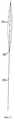
на фиг. 1 показано смачивающее устройство согласно первому варианту выполнения изобретения, включающее мочеприемник и объединенный с ним контейнер для смачивающей жидкости,
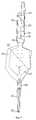
на фиг. 2 показано смачивающее устройство согласно второму варианту выполнения изобретения, включающее мочеприемник и объединенный с ним невскрытый пакет для смачивающей жидкости, находящийся в рабочем положении во впускном отверстии мочеприемника,
на фиг. 3 показан невскрытый пакет смачивающего устройства, показанного на фиг. 2, в рабочем положении во впускном отверстии мочеприемника,
на фиг. 4 показан вид спереди невскрытого пакета смачивающего устройства, показанного на фиг. 2, в развернутом виде до установки его в рабочее положение во впускном отверстии мочеприемника,
на фиг. 5 представлен вид сбоку невскрытого пакета, показанного на фиг. 4,
на фиг. 6 показан вид в перспективе невскрытого пакета смачивающего устройства, показанного на фиг.2, в сложенном виде и готового к установке во впускном отверстии мочеприемника в рабочее положение,
фиг. 7 соответствует фиг.2, но пакет для смачивающей жидкости вскрыт, и
фиг. 8 соответствует фиг. 3, но пакет для смачивающей жидкости вскрыт.Below, as examples, embodiments of the invention are described with reference to the accompanying drawings, where:
in FIG. 1 shows a wetting device according to a first embodiment of the invention, comprising a urinal and an associated container for a wetting liquid,
in FIG. 2 shows a wetting device according to a second embodiment of the invention, comprising a urinal and an unopened wetting liquid bag integrated therewith, in a working position in the inlet of the urinal,
in FIG. 3 shows an unopened bag of the wetting device shown in FIG. 2, in the operating position in the inlet of the urinal,
in FIG. 4 is a front view of an unopened package of the wetting device shown in FIG. 2, in expanded form before installing it in the working position in the inlet of the urinal,
in FIG. 5 is a side view of the unopened bag shown in FIG. 4,
in FIG. 6 shows a perspective view of an unopened package of the wetting device shown in FIG. 2, folded and ready to be installed in the inlet of the urinal in the operating position,
FIG. 7 corresponds to FIG. 2, but the wetting bag has been opened, and
FIG. 8 corresponds to FIG. 3, but the wetting bag has been opened.
На фиг. 1 показано смачивающее устройство 10 согласно изобретению, включающее мочеприемник 1 из прозрачной гибкой пластмассы. Мочеприемник 1 имеет в своей передней части удлиненный карман 2 достаточной глубины для приема гидрофильного урологического катетера 3 по меньшей мере на длину его ввода. Мочеприемник 1 имеет также примыкающую к задней части кармана 2 мочеприемную камеру 12, которая сообщается с карманом 2. В задней части мочеприемника 1 имеется впускной отверстие 14, через которое гидрофильный урологический катетер 3 может быть вставлен в мочеприемник 1. In FIG. 1 shows a wetting device 10 according to the invention, comprising a urinal 1 made of transparent flexible plastic. The urinal 1 has in its front part an elongated pocket 2 of sufficient depth to receive a hydrophilic urological catheter 3 at least for the length of its input. The urinal 1 also has a urine chamber 12 adjacent to the back of the pocket 2, which communicates with the pocket 2. At the rear of the urinal 1 there is an inlet 14 through which the hydrophilic urological catheter 3 can be inserted into the urinal 1.
Как видно на фиг.1, катетер 3 имеет расширяющуюся назад часть 16 и удлиненный стержень 18, который проходит вперед от задней части 16 и заканчивается скругленным наконечником 4 на своем переднем конце. Катетер 3 имеет трубчатую полость (не показана), которая идет от открытого конца в задней части 16 к дренажному отверстию 5 в наконечнике 4. As can be seen in FIG. 1, the catheter 3 has a backward extending portion 16 and an elongated shaft 18, which extends forward from the rear portion 16 and ends with a rounded tip 4 at its front end. The catheter 3 has a tubular cavity (not shown) that extends from the open end at the rear 16 to the drainage hole 5 at the tip 4.
К внутренней поверхности мочеприемника 1 прикреплен контейнер в виде пакета 6. Пакет 6 содержит стерильную воду, соляной раствор или другую жидкость, подходящую для смачивания гидрофильного урологического катетера 3, и может быть проткнут или вскрыт иным способом, например путем сжатия рукой, для выливания его содержимого - воды или соляного раствора в карман 2 непосредственно перед использованием катетера 3. A container is attached to the inner surface of the urinal 1 in the form of a packet 6. The packet 6 contains sterile water, saline or other liquid suitable for wetting a hydrophilic urological catheter 3, and can be pierced or opened in another way, for example by compressing it with your hand to pour out its contents - water or saline in pocket 2 immediately before using catheter 3.
Обычно мочеприемник 1 с пакетом 6 и вставленным катетером 3 стерилизуют с использованием этиленоксида. Поскольку пакет 6 содержит стерильную воду или соляной раствор, нет необходимости в стерилизации его содержимого. Соответственно, материал пакета 6 предпочтительно является непроницаемым для этиленоксида и воды. Примерами материалов, соответствующих этим требованиям, но не ограничивающих их выбор, являются поли(винилиденхлорид) (PVDC), многослойная алюминиевая фольга и металлизированные пленки, например металлизированный поли(этилентерефталат). Как альтернатива, могут быть использованы другие процессы стерилизации, например облучение, в этом случае жидкость в пакете 6 можно простерилизовать на месте одновременно с остальными компонентами устройства 10. Typically, an urinal 1 with a bag of 6 and an inserted catheter 3 is sterilized using ethylene oxide. Since bag 6 contains sterile water or saline, there is no need to sterilize its contents. Accordingly, the material of the bag 6 is preferably impermeable to ethylene oxide and water. Examples of materials that meet these requirements, but do not limit their choice, are poly (vinylidene chloride) (PVDC), multilayer aluminum foil, and metallized films, such as metallized poly (ethylene terephthalate). As an alternative, other sterilization processes can be used, for example, irradiation, in which case the liquid in the bag 6 can be sterilized in place simultaneously with the other components of the device 10.
Пакет 6 имеет достаточный объем для поступления в карман 2 такого количества воды или соляного раствора, которое обеспечит смачивание катетера 3 на длину его ввода непосредственно перед использованием. Под "длиной ввода" понимается длина по меньшей мере части удлиненного стержня 18, покрытой гидрофильным материалом, например поливинилпирролидоном, которая вводится в мочеиспускательный канал пациента. Обычно она равна 80-140 мм для женщин и 200-350 мм для мужчин. The bag 6 has a sufficient volume for entering into pocket 2 such an amount of water or saline solution that will wet the catheter 3 by the length of its insertion immediately before use. By "insertion length" is meant the length of at least a portion of the elongated shaft 18 coated with a hydrophilic material, for example polyvinylpyrrolidone, which is inserted into the urethra of the patient. Usually it is equal to 80-140 mm for women and 200-350 mm for men.
Время нахождения катетера 3 в кармане 2 может варьироваться в широком диапазоне, но обычно составляет по меньшей мере 30 секунд. The residence time of the catheter 3 in the pocket 2 can vary over a wide range, but usually is at least 30 seconds.
Местоположение пакета 6 внутри мочеприемника 1 некритично, лишь бы содержимое пакета 6 выливалось в карман 2. Однако предпочтительно, чтобы пакет 6 был расположен как можно ближе к открытому концу кармана 2. В данном варианте выполнения пакет 6 закреплен внутри мочеприемника 1, например приклеен к нему. Однако понятно, что пакет 6 может фактически свободно перемещаться в мочеприемнике 1. Существенным является то, что пакет 6 находится внутри мочеприемника 1, так что эти два компонента образуют единый блок. The location of the bag 6 inside the urinal 1 is uncritical, as long as the contents of the bag 6 are poured into the pocket 2. However, it is preferable that the bag 6 is located as close as possible to the open end of the pocket 2. In this embodiment, the bag 6 is fixed inside the urinal 1, for example, glued to it . However, it is understood that the bag 6 can actually move freely in the urinal 1. It is essential that the bag 6 is located inside the urinal 1, so that these two components form a single unit.
При использовании катетер 3 вводят в мочеприемник 1 через впускное отверстие 14, а удлиненный стержень 18 вводят в карман 2, как показано на фиг. 1. Затем впускное отверстие 14 закрывают, например завязывая в узел материал, из которого сделаны стенки отверстия, или зажимая впускное отверстие 14 зажимом. Затем пакет 6 вскрывают, например прикладывая к нему давление через материал мочеприемника 1, для выливания смачивающей жидкости в карман 2 и оставляют мокнуть катетер 3 в смачивающей жидкости заданное время для смачивания его гидрофильной наружной поверхности. In use, the catheter 3 is inserted into the urinal 1 through the inlet 14, and the elongated shaft 18 is inserted into the pocket 2, as shown in FIG. 1. Then, the inlet 14 is closed, for example by tying into a knot the material from which the walls of the hole are made, or by clamping the inlet 14. Then the bag 6 is opened, for example by applying pressure to it through the material of the urinal 1, to pour the wetting liquid into the pocket 2 and leave the catheter 3 in the wetting liquid for a predetermined time to wet its hydrophilic outer surface.
Альтернативно, мочеприемник 1 может иметь закрытый конец вместо впускного отверстия, при этом катетер 3 заранее вставлен в мочеприемник 1. Наличие впускного отверстия 14 предпочтительно в том случае, когда стерилизующим средством является этиленоксид, поскольку обеспечивается ввод этиленоксида внутрь мочеприемника 1 и его удаление. Alternatively, the urinal 1 may have a closed end instead of the inlet, with the catheter 3 pre-inserted into the urinal 1. The presence of the inlet 14 is preferable when the sterilizing agent is ethylene oxide, since ethylene oxide is introduced into the urinal 1 and removed.
После смачивания катетера 3 в течение заданного времени мочеприемник 1 переворачивают "вверх ногами" и отрывают самый кончик кармана 2. Затем выводят удлиненный стержень 18 катетера 3 через отверстие на переднем конце кармана 2 и вводят его в мочеиспускательный канал пациента до тех пор, пока расширяющаяся часть 16 не создаст механического уплотнения в отверстии. Поэтому нет необходимости непосредственно держать катетер 3 для введения его в мочеиспускательный канал, что является преимуществом, поскольку наружная поверхность катетера 3 будет скользкой из-за ее смачивания и ее трудно держать в руке, и, кроме того, поскольку удается избежать опасности внесения инфекции в катетер 3 во время этой операции. After wetting the catheter 3 for a predetermined time, the urinal 1 is turned upside down and the very tip of the pocket 2 is torn off. Then the elongated shaft 18 of the catheter 3 is brought out through the hole on the front end of the pocket 2 and inserted into the urethra of the patient until the expanding part 16 will not create a mechanical seal in the hole. Therefore, there is no need to directly hold the catheter 3 for insertion into the urethra, which is an advantage since the outer surface of the catheter 3 will be slippery due to its wetting and it is difficult to hold it in your hand, and in addition, since the risk of introducing the infection into the catheter is avoided 3 during this operation.
Моча из мочевого пузыря пациента идет в обратном направлении через трубчатую полость катетера 3 в мочеприемную камеру 12. Катетер 3 выводят назад внутрь мочеприемника 1 и открытый конец кармана 2 закрывают, например завязывая в узел материал, из которого он сделан, или зажимая карман 2 зажимом. Затем можно сделать отверстие в мочеприемной камере 12 для выливания из нее собранной мочи, после чего мочеприемник 1 можно выбросить. Urine from the patient’s bladder flows back through the tubular cavity of the catheter 3 into the urine chamber 12. The catheter 3 is brought back into the urinal 1 and the open end of the pocket 2 is closed, for example by tying the material from which it is made or by clamping the pocket 2 with a clip. Then you can make a hole in the urine chamber 12 to pour out the collected urine from it, after which the urinal 1 can be discarded.
На фиг. 2 и 3 показан альтернативный вариант предлагаемого смачивающего устройства 110. Смачивающее устройство 100 содержит мочеприемник 101 из гибкой прозрачной пластмассы, который соответствует мочеприемнику 1 смачивающего устройства 10, описанному выше в связи с фиг.1. А именно, мочеприемник 101 имеет на своем переднем конце идущий вниз удлиненный карман 102, за которым находится сообщающаяся с ним мочеприемная камера 112, а в задней части мочеприемника 101 расположено впускное отверстие 114. In FIG. 2 and 3 show an alternative embodiment of the proposed
Аналогично смачивающему устройству 10, показанному на фиг.1, гидрофильный урологический катетер 103 имеет расширяющуюся назад часть 116, удлиненный стержень 118, выступающий вперед от задней части 116, и открытую трубчатую полость (не показана), которая идет от заднего конца задней части 116 к дренажному отверстию 105 в скругленном наконечнике 104 на переднем конце катетера 103, и может быть помещен в мочеприемник 101 через впускное отверстие 114 так, что катетер 103 войдет в карман 102 предпочтительно по меньшей мере на длину ввода. Similar to the wetting device 10 shown in FIG. 1, the hydrophilic
Как видно на фиг. 3, пакет 106, содержащий смачивающую жидкость, вставлен во впускное отверстие 114 в рабочем положении, в котором он удерживается посредством посадки за счет трения. Пакет 106 имеет переднюю часть 120, которая в его рабочем положении проходит вперед во впускное отверстие 114, и заднюю часть 122, которая в рабочем положении выступает назад из впускного отверстия 114. As seen in FIG. 3, a
Предпочтительно, чтобы пакет 106 был выполнен из алюминиевой фольги, в особенности если в качестве стерилизующего средства для устройства 110 используется этиленоксид, а пакет содержит стерильную воду или соляной раствор. Если в качестве стерилизующего средства для устройства 110 используется этиленоксид, посадка пакета 106 во впускном отверстии 114 оказывается недостаточно плотной для того, чтобы не допустить протекания этиленоксида внутрь мочеприемника 101 и из него и стерилизации внутренней поверхности мочеприемника 101 и наружных поверхностей пакета 106 и катетера 103. Смачивающая жидкость хранится в пакете 106 за счет его уплотнения по периферии. Preferably, the
На фиг. 4 и 5 показан передний край 124 передней части 120 пакета 106. От переднего края 124 назад идет линия 126 разрыва. От переднего края 124 пакета 106 по одну сторону от линии 126 разрыва выступает вперед первый язычок 126. По другую сторону от линии 126 разрыва имеется удлиненный второй язычок 130, показанный в развернутом положении, в котором он выступает вперед от переднего края 124. In FIG. 4 and 5, a
Как показано на фиг. 6, удлиненный второй язычок 130 можно перемещать назад, поворачивая его вокруг переднего края 124, из развернутого положения, показанного на фиг. 4 и 5, в сложенное положение, в котором второй язычок 130 отходит назад от переднего края 124. Когда второй язычок 130 находится в сложенном положении, пакет 106 вставляют во впускное отверстие 114 в рабочее положение, показанное на фиг.2 и 3. As shown in FIG. 6, the elongated
На фиг. 2 и 3 видно, что размеры второго язычка 130 таковы, что когда пакет 106 находится в рабочем положении, часть 132 второго язычка 130, к которой прикладывается тянущая сила, выступает назад из впускного отверстия 114 мочеприемника 101 и образует часть задней части 122 пакета 106. In FIG. 2 and 3, it can be seen that the dimensions of the
На фиг. 7 и 8 показано, что нужно делать с пакетом 106, чтобы вылить его содержимое в карман 102 для смачивания наружного гидрофильного покрытия катетера 103. Пользователь держит первый язычок 128 сквозь гибкую прозрачную пластмассу, из которой выполнен мочеприемник 101, и затем тянет назад выступающую из впускного отверстия 114 часть 132 второго язычка 130, чтобы разорвать линию 126 разрыва и вылить смачивающую жидкость в карман 102 для увлажнения катетера 103. Предпочтительно, чтобы пакет 106 содержал достаточно смачивающей жидкости для заполнения кармана 102 до уровня, который обеспечивает смачивание катетера 103 на длину ввода. In FIG. Figures 7 and 8 show what needs to be done with the
После выливания смачивающей жидкости в карман 102 пакет 106 вынимают из мочеприемника 101 и выбрасывают. Затем мочеприемник 101 и катетер 103 используют так же, как описано выше для смачивающего устройства 10, показанного на фиг. 1. After pouring the wetting liquid into the
При необходимости мочеприемник 101 может представлять собой закрытый мочеприемник с заранее помещенными внутрь пакетом 106 и катетером 103. В этом случае мочеприемник 101 имеет такую конструкцию, что пакет 106 может быть вскрыт указанным выше образом через материал мочеприемника 101. If necessary, the
Смачивающее устройство 110, описанное выше в связи с фиг.2-8, помимо прочих, имеет следующие преимущества: (1) оно является экологически дружественным в том смысле, что когда пакет 106 выполнен из алюминиевой фольги, пакет можно выбросить отдельно от мочеприемника 101, что делает возможной утилизацию алюминиевой фольги, и (2) пакет 106 может лучше противостоять периодическому давлению, которое обычно действует на смачивающее устройство при его упаковке и в процессе стерилизации, поскольку не нужно вскрывать пакет 106 путем приложения к нему непосредственного давления через материал мочеприемника 101, для чего край пакета должен бы быть значительно менее прочным, так как нельзя приложить высокое давление через мочеприемник 101, не повредив его. The wetting
В вариантах выполнения, описанных выше в качестве примеров со ссылками на прилагаемые чертежи, запас жидкости для смачивания гидрофильного урологического катетера хранится в отдельном пакете, находящемся в смачивающем сосуде. Специалистам в данной области техники понятно, что без отхода от сущности изобретения запас жидкости может храниться в камере, выполненной в материале смачивающего сосуда за одно целое с ним. In the embodiments described above by way of example with reference to the accompanying drawings, the fluid supply for wetting a hydrophilic urological catheter is stored in a separate bag located in a wetting vessel. Those skilled in the art will understand that, without departing from the spirit of the invention, a supply of liquid can be stored in a chamber made in the material of a wetting vessel in one piece with it.
Claims (25)
Translated fromRussian25.01.1996 по пп.1, 2, 4, 6, 7, 10, 14, 23-25;
22.01.1997 по пп. 3, 5, 8, 9, 11-13, 15-22, а также по пп.4, 6, 7, 10, 14, 23-25 в части, содержащей зависимость соответственно от пп.3, 5, 8, 9, 11-13, 15-22.Priority on points:
01/25/1996 according to claims 1, 2, 4, 6, 7, 10, 14, 23-25;
01/22/1997 by claims 3, 5, 8, 9, 11-13, 15-22, and also according to claims 4, 6, 7, 10, 14, 23-25 in the part containing the dependence, respectively, on claims 3, 5, 8, 9 11-13, 15-22.
Applications Claiming Priority (2)
| Application Number | Priority Date | Filing Date | Title |
|---|---|---|---|
| SE9600276-4 | 1996-01-25 | ||
| SE9600276ASE9600276D0 (en) | 1996-01-25 | 1996-01-25 | A wetting device for wetting a hydrophilic catheter and a urine collection bag incorporating said device |
Publications (2)
| Publication Number | Publication Date |
|---|---|
| RU98115714A RU98115714A (en) | 2000-06-27 |
| RU2177338C2true RU2177338C2 (en) | 2001-12-27 |
Family
ID=20401150
Family Applications (1)
| Application Number | Title | Priority Date | Filing Date |
|---|---|---|---|
| RU98115714/14ARU2177338C2 (en) | 1996-01-25 | 1997-01-22 | Hydrophilic urethral catheter with water bag |
Country Status (28)
| Country | Link |
|---|---|
| US (4) | US6409717B1 (en) |
| EP (4) | EP0959930B2 (en) |
| JP (1) | JP3320425B2 (en) |
| KR (1) | KR100287655B1 (en) |
| CN (1) | CN1165351C (en) |
| AR (1) | AR005561A1 (en) |
| AT (2) | ATE229357T1 (en) |
| AU (2) | AU706432B2 (en) |
| BR (1) | BR9707194A (en) |
| CA (1) | CA2241989C (en) |
| CZ (1) | CZ292341B6 (en) |
| DE (2) | DE29724914U1 (en) |
| DK (4) | DK2226042T3 (en) |
| ES (2) | ES2188889T5 (en) |
| HU (1) | HU228762B1 (en) |
| IL (1) | IL125427A (en) |
| IS (1) | IS4796A (en) |
| MX (1) | MX9805937A (en) |
| NO (1) | NO312437B1 (en) |
| NZ (1) | NZ326930A (en) |
| PL (1) | PL186070B1 (en) |
| PT (1) | PT959930E (en) |
| RU (1) | RU2177338C2 (en) |
| SE (2) | SE9600276D0 (en) |
| TR (1) | TR199801397T2 (en) |
| TW (1) | TW326393B (en) |
| WO (1) | WO1997026937A1 (en) |
| ZA (1) | ZA97535B (en) |
Cited By (4)
| Publication number | Priority date | Publication date | Assignee | Title |
|---|---|---|---|---|
| RU2227081C1 (en)* | 2002-12-02 | 2004-04-20 | Открытое акционерное общество "Северсталь" | Mold for continuous casting |
| RU2580984C2 (en)* | 2009-12-21 | 2016-04-10 | Колопласт А/С | Catheter kit for urinary catheter |
| RU2602717C2 (en)* | 2010-12-17 | 2016-11-20 | Колопласт А/С | Catheter assembly |
| RU2607182C2 (en)* | 2011-08-29 | 2017-01-10 | Колопласт А/С | Closing of flow through catheter |
Families Citing this family (116)
| Publication number | Priority date | Publication date | Assignee | Title |
|---|---|---|---|---|
| SE9600276D0 (en) | 1996-01-25 | 1996-01-25 | Astra Ab | A wetting device for wetting a hydrophilic catheter and a urine collection bag incorporating said device |
| DK172941B1 (en)† | 1996-09-18 | 1999-10-11 | Coloplast As | A urinary catheter assembly |
| SE9702748D0 (en)* | 1997-07-18 | 1997-07-18 | Astra Ab | Barrier material |
| DK147397A (en)* | 1997-12-17 | 1999-06-25 | Coloplast As | Ready-to-use urinary catheter device |
| SE9704712D0 (en)† | 1997-12-17 | 1997-12-17 | Astra Ab | Medical device |
| HUP0103526A3 (en)* | 1998-09-23 | 2002-02-28 | Coloplast As | Catheter set |
| DK174621B1 (en) | 1998-11-20 | 2003-07-28 | Coloplast As | Urinary catheter device with integrated catheter applicator |
| ATE232750T1 (en)* | 1998-11-20 | 2003-03-15 | Coloplast As | METHOD FOR STERILIZING MEDICAL DEVICES WITH HYDROPHILE COATING |
| US6986868B2 (en) | 1998-11-20 | 2006-01-17 | Coloplast A/S | Method for sterilizing a medical device having a hydrophilic coating |
| EP1023882A1 (en) | 1999-01-26 | 2000-08-02 | Coloplast A/S | A urinary catheder assembly |
| SE9900465D0 (en) | 1999-02-12 | 1999-02-12 | Astra Ab | Storage package |
| US7066912B2 (en)* | 1999-12-17 | 2006-06-27 | Astra Tech Ab | Catheter wetting apparatus |
| SE9904635D0 (en)* | 1999-12-17 | 1999-12-17 | Astra Ab | Catheter wetting apparatus |
| EP1420847B1 (en)* | 2001-06-29 | 2008-12-31 | Coloplast A/S | A catheter assembly |
| US7682353B2 (en) | 2001-06-29 | 2010-03-23 | Coloplast A/S | Catheter device |
| US7517343B2 (en)* | 2001-06-29 | 2009-04-14 | Coloplast A/S | Catheter assembly |
| US7311698B2 (en)* | 2001-09-24 | 2007-12-25 | Coloplast A/S | Urinary catheter assembly allowing for non-contaminated insertion of the catheter into a urinary canal |
| BR0212317A (en) | 2001-09-14 | 2004-09-21 | Basell Polyolefine Gmbh | Process for polymerization of olefins in the presence of a catalyst system, use thereof, and polymer |
| ITBO20010091U1 (en)* | 2001-10-31 | 2003-05-01 | Gallini S R L | STERILIZABLE DEVICE FOR URINE DRAINAGE |
| SE0201330D0 (en)* | 2002-04-30 | 2002-04-30 | Astra Tech Ab | Catheter assembly |
| US6991096B2 (en)* | 2002-09-27 | 2006-01-31 | Medtronic Minimed, Inc. | Packaging system |
| US7261701B2 (en)* | 2002-10-03 | 2007-08-28 | 3M Innovative Properties Co. | Skin antiseptic composition dispenser and methods of use |
| US20040074794A1 (en)* | 2002-10-18 | 2004-04-22 | Conway Anthony J. | Catheter wetting system and method |
| WO2004075944A2 (en) | 2003-02-26 | 2004-09-10 | Coloplast A/S | A medical device having a coating comprising hydrogen peroxide and package therefore |
| DE10329128B4 (en)† | 2003-06-27 | 2005-04-28 | Ruesch Willy Gmbh | A urinary catheter |
| ES2683748T5 (en)* | 2003-08-08 | 2024-07-22 | Hollister Inc | Steam hydration of a hydrophilic catheter in a container |
| EP1660168B1 (en) | 2003-09-05 | 2008-12-10 | Cook Urological Inc. | Double ended wire guide |
| USD503335S1 (en)* | 2003-10-07 | 2005-03-29 | Astra Tech Ab | Catheter package |
| DE20319306U1 (en)* | 2003-12-13 | 2005-05-04 | B. Braun Medicare Gmbh & Co. Kg | Urine drainage catheter with provision for lubrication and antisepsis includes flexible tube running along interior of catheter lumen and connected to outlet on catheter tip |
| SE0303525D0 (en)* | 2003-12-22 | 2003-12-22 | Astra Tech Ab | Catheter assembly with osmolality-increasing |
| US7334679B2 (en)* | 2004-03-15 | 2008-02-26 | Hollister Incorporated | Tear open package for hydrophilic-coated catheter |
| USD534649S1 (en) | 2004-06-08 | 2007-01-02 | Astra Tech Ab | Catheter package with collection bag |
| SE0401879D0 (en) | 2004-07-16 | 2004-07-16 | Astra Tech Ab | Folded catheter assembly with adhesive grip |
| US7571804B2 (en) | 2005-03-03 | 2009-08-11 | Coloplast A/S | Package for a medical device |
| US8864730B2 (en) | 2005-04-12 | 2014-10-21 | Rochester Medical Corporation | Silicone rubber male external catheter with absorbent and adhesive |
| US8747882B2 (en)* | 2005-04-21 | 2014-06-10 | Astra Tech Ab | Catheter assembly with bactericidal effect |
| ES2392497T3 (en)* | 2005-07-18 | 2012-12-11 | Dentsply Ih Ab | Urinary catheter |
| EP1922105A4 (en)* | 2005-08-17 | 2010-07-28 | Colorado Catheter Company Inc | Catheterization assembly |
| WO2007038681A2 (en)* | 2005-09-27 | 2007-04-05 | Clemson University | Fluid equilibrated absorbent polymeric materials, devices including same and packaging for same |
| US8328792B2 (en) | 2005-10-27 | 2012-12-11 | C. R. Bard, Inc. | Enhanced pre-wetted intermittent catheter with lubricious coating |
| US20070170080A1 (en)* | 2006-01-26 | 2007-07-26 | Joshua Stopek | Medical device package |
| US8317775B2 (en)* | 2006-03-10 | 2012-11-27 | Adapta Medical, Inc. | Urinary catheterization assembly with vented sheath |
| US7662146B2 (en)* | 2006-03-10 | 2010-02-16 | Colorado Catheter Company, Inc. | Indwelling urinary catheterization assembly |
| EP2308543B1 (en) | 2006-06-08 | 2013-05-29 | Hollister Incorporated | Catheter product package |
| US7601158B2 (en)* | 2006-07-17 | 2009-10-13 | Colorado Catheter Company, Inc. | Devices for handling catheter assembly |
| US8475434B2 (en)* | 2006-08-28 | 2013-07-02 | Astra Tech Ab | Urinary catheter with one way check valve |
| EP1897580B1 (en)* | 2006-09-06 | 2016-07-06 | Medical Service GmbH | Catheter set |
| EP1897579B2 (en)* | 2006-09-06 | 2013-10-16 | Medical Service GmbH | Catheter set |
| US8491552B2 (en) | 2006-09-25 | 2013-07-23 | Adapta Medical, Inc. | External catheter with antiseptic agent |
| US20080097411A1 (en)* | 2006-09-25 | 2008-04-24 | Jamie Glen House | Catheter assemblies having sized sheaths |
| US8888747B2 (en) | 2006-10-12 | 2014-11-18 | Adapta Medical, Inc. | Catheter assembly with vents |
| US7601142B2 (en)* | 2006-10-12 | 2009-10-13 | Colorado Catheter Company, Inc. | Devices for connecting catheter assembly to collection receptacle |
| US7918831B2 (en)* | 2006-10-12 | 2011-04-05 | Colorado Catheter Company, Inc. | Catheter assembly having protective sheath |
| US20080146985A1 (en)* | 2006-12-14 | 2008-06-19 | Jamie Glen House | Body treatment devices and methods |
| US20080172042A1 (en)* | 2007-01-12 | 2008-07-17 | Jamie Glen House | Urinary catheterization assembly with open ended sheath |
| US8177765B2 (en)* | 2007-01-12 | 2012-05-15 | Adapta Medical, Inc. | Collection devices for catheter assemblies |
| US7938807B2 (en) | 2007-01-12 | 2011-05-10 | Adapta Medical, Inc. | Devices and methods for securing catheter assemblies |
| DE102007006905B4 (en) | 2007-02-13 | 2008-12-18 | Medical Service Gmbh | A method of wetting a hydrophilic urinal catheter and associated catheter system |
| WO2008103644A1 (en)* | 2007-02-21 | 2008-08-28 | Colorado Catheter Company, Inc. | Devices for connecting catheter assembly to collection receptacle |
| US20080249482A1 (en)* | 2007-04-05 | 2008-10-09 | Miki Erez | Self catheterization kit |
| ATE536897T1 (en)* | 2007-10-03 | 2011-12-15 | Astra Tech Ab | CATHETER CONTAINER FILLED WITH AN ANTIMICROBIAL COMPOUND |
| US20090099531A1 (en)* | 2007-10-15 | 2009-04-16 | Griesbach Iii Henry Louis | Packaging for selectivity lubricating part of a medical device |
| EP2060296B1 (en)* | 2007-11-19 | 2016-08-24 | Hollister Incorporated | Vapor hydrated catheter assembly and method of making same |
| DE602007008745D1 (en) | 2007-12-21 | 2010-10-07 | Astra Tech Ab | Catheter assembly with folded urine bag |
| USD594115S1 (en) | 2007-12-21 | 2009-06-09 | Astra Tech Ab | Urine drain catheter with collection bag |
| US8409171B2 (en) | 2008-02-28 | 2013-04-02 | Hollister Incorporated | Fluid drainage catheter having an external flow path |
| US20090240214A1 (en)* | 2008-03-19 | 2009-09-24 | Conway Anthony J | Catheter wetting system and method |
| CA2728006A1 (en)* | 2008-07-18 | 2010-01-21 | Coloplast A/S | A blocking device |
| CN101347362B (en)* | 2008-09-01 | 2010-04-14 | 刘亚庆 | Disposal household catheter packed in lubricated package |
| US8444577B2 (en) | 2009-01-05 | 2013-05-21 | Cook Medical Technologies Llc | Medical guide wire |
| US20100312203A1 (en)* | 2009-06-04 | 2010-12-09 | Colorado Catheter Company, Inc. | Tear Away Fluid Collection Container |
| WO2011014201A1 (en) | 2009-07-29 | 2011-02-03 | C. R. Bard, Inc. | Catheter having improved drainage and/or a retractable sleeve and method of using the same |
| WO2011019359A1 (en) | 2009-08-13 | 2011-02-17 | C. R. Bard, Inc. | Catheter having internal hydrating fluid storage and/or catheter package using the same and method of making and/or using the same |
| HUE041823T2 (en) | 2009-09-04 | 2019-05-28 | Dentsply Ih Ab | Catheter assembly with resealable opening |
| US10912917B2 (en) | 2009-12-23 | 2021-02-09 | C. R. Bard, Inc. | Catheter assembly/package utilizing a hydrating/hydrogel sleeve and method of making and using the same |
| EP2542291A4 (en) | 2010-03-04 | 2013-08-07 | Bard Inc C R | CATHETER ASSEMBLY / PACKAGE USING MOISTURIZER / HYDROGEL SLEEVE AND EXTERNAL SHEET LAYER AND METHOD OF MANUFACTURING AND USING THE SAME |
| US9707375B2 (en) | 2011-03-14 | 2017-07-18 | Rochester Medical Corporation, a subsidiary of C. R. Bard, Inc. | Catheter grip and method |
| SE536277C2 (en)* | 2011-06-01 | 2013-07-30 | Catheasy Vaesteraas Ab | Flushing device and kit comprising a flushing device |
| CN103747831B (en) | 2011-08-29 | 2017-02-22 | 科洛普拉斯特公司 | Catheter is activated by manual removal |
| EP3572114A1 (en)* | 2011-12-27 | 2019-11-27 | Dentsply IH AB | Temporarily foldable catheter assembly |
| USD775522S1 (en) | 2011-12-27 | 2017-01-03 | Dentsply Ih Ab | Catheter package |
| EP3747496A1 (en) | 2011-12-27 | 2020-12-09 | Dentsply IH AB | Catheter assembly with resealable opening |
| US10092728B2 (en) | 2012-11-20 | 2018-10-09 | Rochester Medical Corporation, a subsidiary of C.R. Bard, Inc. | Sheath for securing urinary catheter |
| US9872969B2 (en) | 2012-11-20 | 2018-01-23 | Rochester Medical Corporation, a subsidiary of C.R. Bard, Inc. | Catheter in bag without additional packaging |
| US8998882B2 (en) | 2013-03-13 | 2015-04-07 | C. R. Bard, Inc. | Enhanced pre-wetted intermittent catheter with lubricious coating |
| USD734165S1 (en) | 2013-03-14 | 2015-07-14 | Hollister, Inc. | Catheter package |
| DK2968832T3 (en) | 2013-03-14 | 2019-09-09 | Hollister Inc | PACKAGING FOR MEDICAL PRODUCTS |
| CA2917047C (en) | 2013-08-30 | 2019-06-11 | Hollister Incorporated | Device for trans-anal irrigation |
| US10946172B2 (en) | 2013-12-04 | 2021-03-16 | Hollister Incorporated | Urinary catheter protective tips having a fluid reservoir |
| EP3119464B2 (en) | 2014-03-17 | 2023-08-23 | Hollister Incorporated | Intermittent catheters having hydration/gripper devices |
| CA3217507A1 (en) | 2014-05-30 | 2015-12-03 | Hollister Incorporated | Flip open catheter package |
| US9192741B1 (en)* | 2014-06-06 | 2015-11-24 | Sasan Najibi | Catheter and wire holding device |
| DK3166661T3 (en) | 2014-07-08 | 2019-04-23 | Hollister Inc | Portable transanal flushing device |
| US10765796B2 (en) | 2014-07-08 | 2020-09-08 | Hollister Incorporated | Trans anal irrigation platform with bed module |
| WO2016033234A1 (en) | 2014-08-26 | 2016-03-03 | C.R. Bard, Inc | Urinary catheter |
| US9333289B1 (en) | 2015-01-16 | 2016-05-10 | Plas-Tech Engineering, Inc. | Tamper evident closure container |
| WO2016206701A1 (en) | 2015-06-26 | 2016-12-29 | Coloplast A/S | A urinary catheter assembly |
| DK3222316T3 (en)* | 2016-03-24 | 2018-07-30 | Teleflex Life Sciences | Ready-to-use catheter device and method of manufacturing a ready-to-use catheter device |
| US11103676B2 (en) | 2016-04-22 | 2021-08-31 | Hollister Incorporated | Medical device package with flip cap having a snap fit |
| AU2017254706B2 (en) | 2016-04-22 | 2022-04-28 | Hollister Incorporated | Medical device package with a twist cap |
| ES2926920T3 (en)* | 2016-05-25 | 2022-10-31 | Teleflex Life Sciences Pte Ltd | Method for manufacturing a ready-to-use catheter assembly and a ready-to-use catheter assembly |
| JP6821779B2 (en) | 2016-07-08 | 2021-01-27 | ホリスター・インコーポレイテッドHollister Incorporated | Transanal enema therapy device |
| US11167107B2 (en) | 2016-09-27 | 2021-11-09 | Coloplast A/S | Hydrated catheter with sleeve |
| US11497844B2 (en) | 2016-12-14 | 2022-11-15 | Hollister Incorporated | Transanal irrigation device and system |
| WO2018156589A2 (en) | 2017-02-21 | 2018-08-30 | Hollister Incorporated | Medical device package with flip cap having a snap fit |
| AU2018337731C1 (en) | 2017-09-19 | 2024-02-01 | C.R. Bard, Inc. | Urinary catheter bridging device, systems and methods thereof |
| CA3079893A1 (en) | 2017-10-25 | 2019-05-02 | Hollister Incorporated | Caps for catheter packages |
| US11666730B2 (en) | 2017-12-08 | 2023-06-06 | Hollister Incorporated | Package for medical device for ergonomic device removal |
| US11534577B2 (en)* | 2018-06-28 | 2022-12-27 | Adapta Medical, Inc. | Catheters having low viscosity lubricant |
| DK180417B1 (en) | 2018-07-20 | 2021-04-22 | Coloplast As | INTERMITTING URINCATHER FITTING |
| CN109124817A (en)* | 2018-09-27 | 2019-01-04 | 佛山科学技术学院 | A kind of pig vas deferens with lubricating fluid |
| WO2020106812A1 (en) | 2018-11-21 | 2020-05-28 | Hollister Incorporated | Hydration solutions containing volatile solutes and medical device products including the same |
| US11771584B2 (en) | 2018-12-20 | 2023-10-03 | Coloplast A/S | Urine collecting bag |
| CN111731681B (en)* | 2020-07-23 | 2020-11-17 | 苏州微比特自动化有限公司 | Packaging bag (WU JI KE LI) |
| US12433709B2 (en) | 2020-09-04 | 2025-10-07 | Hollister Incorporated | Medical device package with first use indicator label |
| EP4496613A1 (en)* | 2022-03-21 | 2025-01-29 | ConvaTec Limited | A catheter assembly |
Citations (3)
| Publication number | Priority date | Publication date | Assignee | Title |
|---|---|---|---|---|
| US3967728A (en)* | 1973-03-02 | 1976-07-06 | International Paper Company | Catheter package |
| RU2012370C1 (en)* | 1991-09-04 | 1994-05-15 | Николай Иванович Конопкин | Catheter |
| GB2284764A (en)* | 1993-11-30 | 1995-06-21 | Mmg | Catheter and urine collection device assembly |
Family Cites Families (135)
| Publication number | Priority date | Publication date | Assignee | Title |
|---|---|---|---|---|
| US1120549A (en) | 1913-12-18 | 1914-12-08 | Oscar B Schellberg | Catheter-case. |
| US2285932A (en)* | 1939-07-26 | 1942-06-09 | Shell Dev | Process for soil fertilization |
| US2856932A (en)* | 1955-12-16 | 1958-10-21 | Dade Reagents Inc | Bag and tube |
| NL92465C (en) | 1955-12-27 | |||
| US2856936A (en) | 1956-09-19 | 1958-10-21 | Deere & Co | Peanut combine |
| US3005728A (en) | 1956-10-19 | 1961-10-24 | Tee Pak Inc | Cellulosic laminates |
| US3023126A (en) | 1959-01-12 | 1962-02-27 | Union Carbide Corp | Method of bonding a synthetic resin coating to a polyolefin surface and article produced thereby |
| DK102396C (en) | 1959-05-08 | 1965-08-23 | Heberlein & Co Ag | Process for refining cellulosic textile material. |
| US3064800A (en) | 1959-07-16 | 1962-11-20 | Abbott Lane Ind Inc | Package |
| US3035691A (en) | 1960-09-19 | 1962-05-22 | Davol Rubber Co | Package for sterile articles |
| US3216983A (en) | 1961-10-23 | 1965-11-09 | Ind Biology Lab Inc | Reaction products of polyvinylpyrrolidone compounds and polyisocyanates |
| US3198692A (en) | 1963-02-26 | 1965-08-03 | Tee Pak Inc | Polyolefin laminate |
| US3169527A (en) | 1963-05-13 | 1965-02-16 | Sheridan Corp | Lubricated catheter |
| US3345988A (en)* | 1965-05-27 | 1967-10-10 | Sterilon Corp | Catheter lubricating sac |
| GB1043667A (en) | 1965-08-06 | 1966-09-21 | Creed & Co Ltd | Keyboard locking device for teleprinters and like keyboard-controlled apparatus |
| US3421509A (en) | 1965-12-17 | 1969-01-14 | John M Fiore | Urethral catheter |
| JPS4719193Y1 (en) | 1966-04-02 | 1972-06-30 | ||
| US3444860A (en) | 1966-06-06 | 1969-05-20 | Osmah E Harrell | Aseptic catheter assembly with holder introducer |
| US3566874A (en)* | 1968-08-13 | 1971-03-02 | Nat Patent Dev Corp | Catheter |
| US3556294A (en)* | 1968-11-25 | 1971-01-19 | Bard Inc C R | Catheter package with self-contained lubricant |
| US3661634A (en) | 1969-10-31 | 1972-05-09 | Us Interior | Semipermeable osmotic membrane and method of producing same |
| US3648704A (en)* | 1970-07-17 | 1972-03-14 | Frederick E Jackson | Disposable catheter apparatus |
| US3730337A (en) | 1970-11-04 | 1973-05-01 | M White | Asprin-capri or tab-capri |
| US3674195A (en) | 1970-11-24 | 1972-07-04 | Us Envelope Co | Filled and sealed easily opened bag and method of making same |
| US3934721A (en) | 1971-06-04 | 1976-01-27 | Affiliated Hospital Products, Inc. | Packaged catheter arrangement |
| CS154977B1 (en) | 1971-10-08 | 1974-04-30 | ||
| US3794042A (en) | 1972-04-27 | 1974-02-26 | Klotz R De | Portable catheter unit |
| US3975350A (en) | 1972-08-02 | 1976-08-17 | Princeton Polymer Laboratories, Incorporated | Hydrophilic or hydrogel carrier systems such as coatings, body implants and other articles |
| GB1465544A (en) | 1973-03-02 | 1977-02-23 | Int Paper Co | Catheter package |
| US3832253A (en) | 1973-03-21 | 1974-08-27 | Baxter Laboratories Inc | Method of making an inflatable balloon catheter |
| DE2317839A1 (en) | 1973-04-10 | 1974-10-17 | J Matthias Dr Wenderlein | Force lubricated catheters - applying lubricant with antiseptic additives during removal from protective sheath |
| US3886947A (en) | 1973-04-13 | 1975-06-03 | Meadox Medicals Inc | Non-thrombogenic catheter |
| US3926309A (en) | 1973-08-01 | 1975-12-16 | Vicra Sterile Inc | Two layer sterile packaging |
| US3898993A (en)* | 1973-09-25 | 1975-08-12 | Tokuso Taniguchi | Lubricated catheter |
| US3861395A (en) | 1973-09-25 | 1975-01-21 | Tokuso Taniguchi | Automated catheter |
| US3954174A (en) | 1974-09-23 | 1976-05-04 | Becton, Dickinson And Company | Unitary two-compartment package for sterile surgical articles |
| US3958750A (en) | 1974-11-21 | 1976-05-25 | Lawrence Peska Associates, Inc. | Transparent medicine dispenser with hospital medicine card |
| DE2456807C3 (en) | 1974-11-30 | 1981-04-09 | Basf Ag, 6700 Ludwigshafen | Process for the production of polymers of vinylpyrrolidone |
| DE2458217A1 (en)* | 1974-12-09 | 1976-06-10 | Jerry Glen Powers | Ureter catheter with simple, sterile application - connector and drainage arrangement at rear end |
| CA1029338A (en) | 1975-05-16 | 1978-04-11 | Kendall Company (The) | Catheter package |
| JPS5512265Y2 (en) | 1975-06-20 | 1980-03-17 | ||
| JPS5550370Y2 (en) | 1975-09-18 | 1980-11-22 | ||
| US4188954A (en) | 1976-08-05 | 1980-02-19 | The Kendall Company | Catheter with improved balloon assembly |
| US4094967A (en) | 1976-10-22 | 1978-06-13 | Allor Foundation | Iodine-polyvinylpyrrolidone solid product and method of preparation |
| US4128600A (en) | 1977-01-14 | 1978-12-05 | General Mills Chemicals, Inc. | Interpenetrating dual cure resin compositions |
| GB1601691A (en) | 1977-03-05 | 1981-11-04 | Wallace Ltd H G | Surgical devices |
| US4140127A (en) | 1977-04-08 | 1979-02-20 | The Kendall Company | Catheter assembly |
| US4119094A (en) | 1977-08-08 | 1978-10-10 | Biosearch Medical Products Inc. | Coated substrate having a low coefficient of friction hydrophilic coating and a method of making the same |
| US4100309A (en) | 1977-08-08 | 1978-07-11 | Biosearch Medical Products, Inc. | Coated substrate having a low coefficient of friction hydrophilic coating and a method of making the same |
| US4143423A (en) | 1977-10-25 | 1979-03-13 | Sternlieb Jack J | Surgical lubricants |
| US4154244A (en) | 1977-11-21 | 1979-05-15 | Baxter Travenol Laboratories, Inc. | Balloon-type catheter |
| US4246909A (en) | 1978-10-05 | 1981-01-27 | Illinois Tool Works Inc. | Disposable urethral catheter assembly |
| CA1136943A (en) | 1978-10-20 | 1982-12-07 | Christopher A. Nowacki | Catheterization unit |
| US4232608A (en) | 1978-12-04 | 1980-11-11 | Aerojet-General Corporation | Dimer isocyanate liner compositions |
| FR2447328A1 (en) | 1979-01-26 | 1980-08-22 | Oreal | Shampoo sachet made of paper-plastics laminate - has sides and base welded closed and has additional pocket for e.g. gloves |
| US4269310A (en)* | 1979-05-14 | 1981-05-26 | Uson Aurelio C | Aseptic container and manipulator for a urethral catheter having an integral antiseptic solution and lubricant |
| US4318947A (en) | 1979-12-26 | 1982-03-09 | The Kendall Company | Polymer coating and curing process for catheters |
| US4481323A (en) | 1980-05-07 | 1984-11-06 | Medical Research Associates, Ltd. #2 | Hydrocarbon block copolymer with dispersed polysiloxane |
| GB2075347B (en) | 1980-05-08 | 1984-04-18 | Wallace Ltd H G | Improvements in or relating to catheters |
| US4366901A (en) | 1981-02-02 | 1983-01-04 | Medtronic, Inc. | In situ rehydrating in sterile packages |
| US4379506A (en) | 1981-04-02 | 1983-04-12 | Davidson Alan C | Catheter assembly |
| BR8202650A (en) | 1981-05-08 | 1983-04-19 | Maria Asuncion S Estadella | INVOLVEMENT FOR CONTAINING AND INTRODUCING AN INSERIVABLE OBJECT IN THE SPHINCTERS OF HUMAN AND ANIMAL BODIES |
| US4373009A (en) | 1981-05-18 | 1983-02-08 | International Silicone Corporation | Method of forming a hydrophilic coating on a substrate |
| US4773901A (en) | 1981-12-31 | 1988-09-27 | C. R. Bard, Inc. | Catheter with selectively rigidified portion |
| US4515593A (en)* | 1981-12-31 | 1985-05-07 | C. R. Bard, Inc. | Medical tubing having exterior hydrophilic coating for microbiocide absorption therein and method for using same |
| SE430696B (en) | 1982-04-22 | 1983-12-05 | Astra Meditec Ab | PROCEDURE FOR THE PREPARATION OF A HYDROPHILIC COATING AND ANY PROCEDURE MANUFACTURED MEDICAL ARTICLE |
| SE430695B (en) | 1982-04-22 | 1983-12-05 | Astra Meditec Ab | PROCEDURE FOR THE PREPARATION OF A HYDROPHILIC COATING AND ACCORDING TO THE PROCEDURE OF MEDICAL ARTICLES |
| US4417612A (en) | 1982-05-18 | 1983-11-29 | Couture Michael V | Pocket key holder |
| US4769013A (en) | 1982-09-13 | 1988-09-06 | Hydromer, Inc. | Bio-effecting medical material and device |
| US4526579A (en) | 1983-06-17 | 1985-07-02 | Pfizer Inc. | Method for graft copolymerization to natural rubber articles |
| US4551292A (en) | 1984-04-05 | 1985-11-05 | Angiomedics, Inc. | Method for making a catheter with a soft, deformable tip |
| US4652259A (en) | 1984-04-10 | 1987-03-24 | Neil Alexander G B O | Catheter assembly |
| US4657544A (en) | 1984-04-18 | 1987-04-14 | Cordis Corporation | Cardiovascular graft and method of forming same |
| AU4198785A (en) | 1984-05-07 | 1985-11-14 | Lloyd A. Ferreira | Conductive material and biomedical electrode |
| US4589873A (en) | 1984-05-29 | 1986-05-20 | Becton, Dickinson And Company | Method of applying a hydrophilic coating to a polymeric substrate and articles prepared thereby |
| US4622033A (en) | 1984-08-08 | 1986-11-11 | Tokuso Taniguchi | Automated catheter construction |
| US4677143A (en) | 1984-10-01 | 1987-06-30 | Baxter Travenol Laboratories, Inc. | Antimicrobial compositions |
| US4597765A (en) | 1984-12-27 | 1986-07-01 | American Medical Systems, Inc. | Method and apparatus for packaging a fluid containing prosthesis |
| SE447791B (en)* | 1985-04-30 | 1986-12-15 | Astra Meditec Ab | Wetting and storage device for a catheter |
| SE8504501D0 (en) | 1985-09-30 | 1985-09-30 | Astra Meditec Ab | METHOD OF FORMING AN IMPROVED HYDROPHILIC COATING ON A POLYMER SURFACE |
| US4921483A (en) | 1985-12-19 | 1990-05-01 | Leocor, Inc. | Angioplasty catheter |
| GB8611838D0 (en)* | 1986-05-15 | 1986-06-25 | Yarsley Technical Centre Ltd | Hydrophilic copolymers |
| US4692154A (en)* | 1986-06-02 | 1987-09-08 | Illinois Tool Works Inc. | Catheter guide |
| US4772275A (en) | 1987-03-09 | 1988-09-20 | Prn Services, Inc. | Sheath for devices for injecting or withdrawing body fluids |
| US5094876A (en)* | 1987-04-10 | 1992-03-10 | University Of Florida | Surface modified surgical instruments, devices, implants, contact lenses and the like |
| DE3814135A1 (en) | 1987-05-06 | 1988-11-24 | Wilkinson Sword Gmbh | METHOD FOR PRODUCING A HYDROPHILIC COATING ON A MOLDED PART AND USING THE METHOD OF A SHAVER |
| US4863442A (en) | 1987-08-14 | 1989-09-05 | C. R. Bard, Inc. | Soft tip catheter |
| US4811847A (en) | 1988-03-14 | 1989-03-14 | Reif Thomas H | Urinary catheter package |
| EP0418247A1 (en) | 1988-03-23 | 1991-03-27 | E.I. Du Pont De Nemours And Company | Low coefficient of friction surface |
| EP0336984B1 (en) | 1988-04-09 | 1990-12-27 | Hewlett-Packard GmbH | Measuring probe |
| US4898591A (en) | 1988-08-09 | 1990-02-06 | Mallinckrodt, Inc. | Nylon-PEBA copolymer catheter |
| US4928830A (en) | 1988-10-31 | 1990-05-29 | Board Of Regents, The University Of Texas System | Suctioning supply kit |
| US5091205A (en) | 1989-01-17 | 1992-02-25 | Union Carbide Chemicals & Plastics Technology Corporation | Hydrophilic lubricious coatings |
| EP0423855B1 (en) | 1989-10-16 | 1994-07-20 | Cordis Europa N.V. | Packaging |
| IE62145B1 (en) | 1990-01-30 | 1994-12-14 | Bard C R Ireland Ltd | Catheter packaging system |
| DK146790D0 (en) | 1990-06-15 | 1990-06-15 | Meadox Surgimed As | PROCEDURE FOR THE PREPARATION OF A FERTILIZER COATING COATING AND MEDICAL INSTRUMENT WITH COATING COATING |
| US5160559A (en) | 1990-10-31 | 1992-11-03 | Scimed Life Systems, Inc. | Method for forming a guide catheter tip bond |
| US5160790A (en) | 1990-11-01 | 1992-11-03 | C. R. Bard, Inc. | Lubricious hydrogel coatings |
| EP0556316B1 (en) | 1990-11-09 | 1997-01-22 | Boston Scientific Corporation | Guidewire for crossing occlusions in blood vessels |
| US5125416A (en) | 1990-12-11 | 1992-06-30 | University Of Massachusetts Medical Center | Guidewire holder |
| US5147341A (en) | 1991-03-05 | 1992-09-15 | Starke Richard N | Self contained urinary catheter assembly |
| US5433713A (en) | 1991-04-15 | 1995-07-18 | Cordis Corporation | Polyetheramide tubing for medical devices |
| US5242428A (en) | 1991-10-04 | 1993-09-07 | Aubrey Palestrant | Apparatus for wetting hydrophilic-coated guide wires and catheters |
| US5217493A (en) | 1992-03-11 | 1993-06-08 | Board Of Regents, The University Of Texas System | Antibacterial coated medical implants |
| US5226530A (en) | 1992-03-23 | 1993-07-13 | Golden John H | Prelubricated urinary catheter and package assembly |
| DE9218987U1 (en) | 1992-04-21 | 1997-03-13 | Cordis Corp., Miami Lakes, Fla. | Polyetheramide hose for medical devices |
| US5209726A (en) | 1992-05-04 | 1993-05-11 | Goosen Carl C | Self-lubricating urethral catheter and method for self-catheterization |
| DK172393B1 (en) | 1992-06-10 | 1998-05-18 | Maersk Medical As | Process for producing an article having friction-reducing surface coating, coating material for use in the manufacture of such article, and using an osmolality-increasing compound in slurry or emulsified form in the coating material |
| DK172850B1 (en) | 1992-09-18 | 1999-08-16 | Maersk Medical As | Process for making an article with friction-reducing surface coating as well as coating material for use |
| EP0592870A1 (en) | 1992-09-30 | 1994-04-20 | C.R. Bard, Inc. | Process for preparing functionally coated expanded products from expandable tubing and the expanded products produced thereby |
| US5342386A (en) | 1992-10-26 | 1994-08-30 | Cordis Corporation | Catheter with multiple flexibilities along the shaft |
| DK7193B (en) | 1993-01-21 | 1994-07-22 | Coloplast As | Process for preparing a hydrophilic coating on a surface and medical article prepared by the method |
| US5531715A (en) | 1993-05-12 | 1996-07-02 | Target Therapeutics, Inc. | Lubricious catheters |
| US5454798A (en)* | 1993-05-14 | 1995-10-03 | Mentor Corporation | Disposable urine bag |
| US5322163A (en) | 1993-06-09 | 1994-06-21 | Plastofilm Industries, Inc. | Catheter tray package with lockable insert |
| DE69324136T2 (en) | 1993-06-18 | 1999-08-26 | Schneider (Europe) Gmbh | A packaging holding a medical instrument under controlled environmental conditions |
| US5402886A (en) | 1993-07-16 | 1995-04-04 | Schneider (Usa) Inc. | Storage container for intravascular catheters |
| US5849843A (en) | 1993-11-16 | 1998-12-15 | Baxter International Inc. | Polymeric compositions for medical packaging and devices |
| ES2141928T5 (en) | 1994-03-02 | 2009-04-16 | Boston Scientific Limited | BALLS OF ELASTOMERO COPOLIMERO IN BLOCKS FOR CATHETER. |
| DE4412754C2 (en) | 1994-04-13 | 1999-09-30 | Via Log Medikalprodukte Gmbh K | Medical instrument packaging |
| TW295570B (en) | 1994-05-04 | 1997-01-11 | Ciba Geigy Ag | |
| US5409104A (en) | 1994-06-01 | 1995-04-25 | Ciba-Geigy Corporation | Contact lens package having improved access features |
| DE9413716U1 (en) | 1994-08-25 | 1994-10-27 | Süddeutsche Feinmechanik GmbH, 63607 Wächtersbach | Packaging for a preferably sterilized medical device |
| CN1056117C (en) | 1994-08-30 | 2000-09-06 | 中国康复研究中心 | High hydrated elastomer formation such as catheter and making method thereof |
| SE9404486D0 (en) | 1994-12-22 | 1994-12-22 | Astra Ab | catheter |
| US5662960A (en) | 1995-02-01 | 1997-09-02 | Schneider (Usa) Inc. | Process for producing slippery, tenaciously adhering hydrogel coatings containing a polyurethane-urea polymer hydrogel commingled with a poly (n-vinylpyrrolidone) polymer hydrogel |
| WO1996030277A1 (en) | 1995-03-29 | 1996-10-03 | Coloplast A/S | Applicator and method for use in non-contaminating application of a medical catheter |
| SE9600276D0 (en) | 1996-01-25 | 1996-01-25 | Astra Ab | A wetting device for wetting a hydrophilic catheter and a urine collection bag incorporating said device |
| US5738213A (en) | 1996-03-22 | 1998-04-14 | Merit Medical Systems, Inc. | Guidewire holder with easy guidewire access |
| SE9602352D0 (en) | 1996-06-14 | 1996-06-14 | Astra Ab | Catheter package |
| AU4062197A (en) | 1996-08-14 | 1998-03-06 | Medical Marketing Group, Inc. | Prelubricated urinary catheter and package assembly |
| SE507378C3 (en) | 1996-09-02 | 1998-06-29 | Volvo Lastvagnar Ab | Compressed air system for trucks |
| DK172941B1 (en) | 1996-09-18 | 1999-10-11 | Coloplast As | A urinary catheter assembly |
| ATE188622T1 (en) | 1996-11-01 | 2000-01-15 | Coloplast As | A BLADDER CATHETER SET WITH A READY-TO-USE CATHETER |
| US5776611A (en) | 1996-11-18 | 1998-07-07 | C.R. Bard, Inc. | Crosslinked hydrogel coatings |
- 1996
- 1996-01-25SESE9600276Apatent/SE9600276D0/enunknown
- 1997
- 1997-01-22EPEP97901879Apatent/EP0959930B2/ennot_activeExpired - Lifetime
- 1997-01-22KRKR1019980705694Apatent/KR100287655B1/ennot_activeExpired - Fee Related
- 1997-01-22WOPCT/SE1997/000096patent/WO1997026937A1/enactiveIP Right Grant
- 1997-01-22DEDE29724914Upatent/DE29724914U1/ennot_activeExpired - Lifetime
- 1997-01-22CZCZ19982328Apatent/CZ292341B6/ennot_activeIP Right Cessation
- 1997-01-22EPEP02008834Apatent/EP1245205B1/ennot_activeExpired - Lifetime
- 1997-01-22EPEP10164803.8Apatent/EP2226042B1/ennot_activeExpired - Lifetime
- 1997-01-22TWTW086100674Apatent/TW326393B/enactive
- 1997-01-22HUHU9901019Apatent/HU228762B1/enunknown
- 1997-01-22DKDK10164803.8Tpatent/DK2226042T3/enactive
- 1997-01-22NZNZ326930Apatent/NZ326930A/enunknown
- 1997-01-22ESES97901879Tpatent/ES2188889T5/ennot_activeExpired - Lifetime
- 1997-01-22USUS08/809,481patent/US6409717B1/ennot_activeExpired - Lifetime
- 1997-01-22PLPL97327859Apatent/PL186070B1/enunknown
- 1997-01-22TRTR1998/01397Tpatent/TR199801397T2/enunknown
- 1997-01-22JPJP52678197Apatent/JP3320425B2/ennot_activeExpired - Fee Related
- 1997-01-22PTPT97901879Tpatent/PT959930E/enunknown
- 1997-01-22DKDK02008834.0Tpatent/DK1245205T3/enactive
- 1997-01-22CACA002241989Apatent/CA2241989C/ennot_activeExpired - Lifetime
- 1997-01-22BRBR9707194Apatent/BR9707194A/ennot_activeIP Right Cessation
- 1997-01-22ESES10164802Tpatent/ES2386874T3/ennot_activeExpired - Lifetime
- 1997-01-22EPEP10164802Apatent/EP2226041B1/ennot_activeExpired - Lifetime
- 1997-01-22DKDK10164802.0Tpatent/DK2226041T3/enactive
- 1997-01-22ZAZA9700535Apatent/ZA97535B/enunknown
- 1997-01-22RURU98115714/14Apatent/RU2177338C2/enactive
- 1997-01-22CNCNB971931135Apatent/CN1165351C/ennot_activeExpired - Lifetime
- 1997-01-22DKDK97901879.3Tpatent/DK0959930T4/enactive
- 1997-01-22AUAU15626/97Apatent/AU706432B2/ennot_activeExpired
- 1997-01-22ATAT97901879Tpatent/ATE229357T1/enactive
- 1997-01-22ATAT10164802Tpatent/ATE556680T1/enactive
- 1997-01-22ILIL12542797Apatent/IL125427A/ennot_activeIP Right Cessation
- 1997-01-22DEDE69717860Tpatent/DE69717860T3/ennot_activeExpired - Lifetime
- 1997-01-24ARARP970100315Apatent/AR005561A1/enunknown
- 1998
- 1998-07-07SESE9802435Apatent/SE522331C2/ennot_activeIP Right Cessation
- 1998-07-13ISIS4796Apatent/IS4796A/enunknown
- 1998-07-23MXMX9805937Apatent/MX9805937A/enunknown
- 1998-07-23NONO19983406Apatent/NO312437B1/ennot_activeIP Right Cessation
- 1999
- 1999-04-01AUAU23558/99Apatent/AU718029B2/ennot_activeExpired
- 2002
- 2002-05-31USUS10/160,390patent/US6736805B2/ennot_activeExpired - Lifetime
- 2004
- 2004-01-20USUS10/762,034patent/US7087048B2/ennot_activeExpired - Fee Related
- 2006
- 2006-06-15USUS11/454,657patent/US7615045B2/ennot_activeExpired - Fee Related
Patent Citations (3)
| Publication number | Priority date | Publication date | Assignee | Title |
|---|---|---|---|---|
| US3967728A (en)* | 1973-03-02 | 1976-07-06 | International Paper Company | Catheter package |
| RU2012370C1 (en)* | 1991-09-04 | 1994-05-15 | Николай Иванович Конопкин | Catheter |
| GB2284764A (en)* | 1993-11-30 | 1995-06-21 | Mmg | Catheter and urine collection device assembly |
Cited By (5)
| Publication number | Priority date | Publication date | Assignee | Title |
|---|---|---|---|---|
| RU2227081C1 (en)* | 2002-12-02 | 2004-04-20 | Открытое акционерное общество "Северсталь" | Mold for continuous casting |
| RU2580984C2 (en)* | 2009-12-21 | 2016-04-10 | Колопласт А/С | Catheter kit for urinary catheter |
| US9561343B2 (en) | 2009-12-21 | 2017-02-07 | Coloplast A/S | Package with a spiral space configured for storing and dispensing a urinary catheter |
| RU2602717C2 (en)* | 2010-12-17 | 2016-11-20 | Колопласт А/С | Catheter assembly |
| RU2607182C2 (en)* | 2011-08-29 | 2017-01-10 | Колопласт А/С | Closing of flow through catheter |
Also Published As
Similar Documents
| Publication | Publication Date | Title |
|---|---|---|
| RU2177338C2 (en) | Hydrophilic urethral catheter with water bag | |
| KR100798984B1 (en) | Conduit wetting device | |
| US7066912B2 (en) | Catheter wetting apparatus | |
| DK2027881T4 (en) | Urinary catheter set | |
| CN102151352A (en) | Catheter assembly and manufacturing method thereof | |
| AU2006220137A1 (en) | A package for a medical device |