RU2176907C2 - Device for carrying out vertebral column osteosynthesis - Google Patents
Device for carrying out vertebral column osteosynthesisDownload PDFInfo
- Publication number
- RU2176907C2 RU2176907C2RU99121462/14ARU99121462ARU2176907C2RU 2176907 C2RU2176907 C2RU 2176907C2RU 99121462/14 ARU99121462/14 ARU 99121462/14ARU 99121462 ARU99121462 ARU 99121462ARU 2176907 C2RU2176907 C2RU 2176907C2
- Authority
- RU
- Russia
- Prior art keywords
- fixing
- screws
- axial
- heads
- holders
- Prior art date
Links
Images


Landscapes
- Surgical Instruments (AREA)
Abstract
Description
Translated fromRussianИзобретение относится к медицине, а именно к травматологии и нейрохирургии, и предназначено для фиксации позвоночника при лечении повреждений и заболеваний. The invention relates to medicine, namely to traumatology and neurosurgery, and is intended for fixation of the spine in the treatment of injuries and diseases.
Известен фиксатор позвоночника французской фирмы "Sofamor Danek", система "Tenor", для лечения повреждений и заболеваний позвоночника, содержащий винты с головками, узлы фиксации винтов, осевые стержни и поперечные стяжки. Known spine fixer of the French company "Sofamor Danek", the system "Tenor", for the treatment of injuries and diseases of the spine, containing screws with heads, screw fixation nodes, axial rods and cross ties.
Недостатком известного устройства является то, что трудно адаптировать узлы фиксации винтов и осевые стержни между собой во время операции, узлы фиксации имеют большие размеры, не создается жесткая рамная конструкция из поперечных стяжек, что ведет к повышенной травматизации паравертебральных мышц и возможности ротационных смещений позвонков в послеоперационном периоде при боковой нестабильности. A disadvantage of the known device is that it is difficult to adapt the screw fixation nodes and axial rods to each other during surgery, the fixation nodes are large, a rigid frame structure is not created from transverse couplers, which leads to increased trauma to the paravertebral muscles and the possibility of rotational displacement of the vertebrae in the postoperative period with lateral instability.
Известен внутренний транспедикулярный фиксатор позвоночника фирмы "Медбиотех" ТУ РБ 14523150.001-95, ТУ РБ 14523150.002-95, ТУ РБ 14523150.003-95, содержащий винты с шестигранными головками, узлы фиксации винтов, осевые стержни. Known internal transpedicular spine retainer company "Medbiotech" TU RB 14523150.001-95, TU RB 14523150.002-95, TU RB 14523150.003-95, containing screws with hexagonal heads, screw fixation nodes, axial rods.
Недостатком этой конструкции является то, что снижена надежность фиксации винтов в послеоперационном периоде при длительной циклической нагрузке, не предусмотрены поперечные стяжки осевых стержней. The disadvantage of this design is that the reliability of fixing the screws in the postoperative period with a long cyclic load is reduced, there are no transverse ties of the axial rods.
Наиболее близкой к заявляемому является другая модель внутреннего транспедикулярного фиксатора позвоночника фирмы "Медбиотех", содержащая винты с цилиндрическими головками, узлы фиксации винтов, состоящих из корпусов держателей со сквозными шлицевыми и осевыми отверстиями, расположенными в перпендикулярных плоскостях, держателей винтов, имеющих шлицевые головки со сквозными отверстиями и резьбовыми концами, вводимые в шлицевые отверстия держателей в корпусах, фиксирующих гаек, резьбовых осевых стержней с упорными гайками, поперечных стяжек осевых стержней (ТУ РБ 14523150.003-95). Closest to the claimed one is another model of the internal transpedicular spinal fixer of the Medbiotech company, which contains screws with cylindrical heads, screw fixation nodes consisting of holder bodies with through spline and axial holes located in perpendicular planes, screw holders with slotted heads with through holes and threaded ends inserted into the slotted holes of the holders in the housings, fixing nuts, threaded axial rods with thrust nuts, transverse x screeds pivots (TU RB 14523150.003-95).
Недостатком этого устройства является то, что крепление корпусов держателей на осевых резьбовых стержнях осуществляется с помощью упорных гаек, в поперечных стяжках стопорение перемычек осуществляется к резьбовой поверхности осевых стержней, что не обеспечивает надежной фиксации элементов конструкции при ротации позвонков в послеоперационном периоде. Кроме того, при циклической нагрузке в месте контакта цилиндрической головки винта и корпуса держателя образуется выработка за счет малой площади соприкосновения поверхностей с последующим смещением головки в отверстии держателя. The disadvantage of this device is that the holders of the holders are mounted on the axial threaded rods using thrust nuts, in the cross ties, the jumpers are locked to the threaded surface of the axial rods, which does not provide reliable fixation of the structural elements during the rotation of the vertebrae in the postoperative period. In addition, during cyclic loading at the point of contact of the cylindrical screw head and the holder body, a production is formed due to the small contact area of the surfaces with subsequent displacement of the head in the holder hole.
Целью настоящего изобретения является обеспечение надежности фиксации позвонков при боковой нестабильности поврежденного сегмента позвоночника, снижение травматичности наложения устройства. The aim of the present invention is to ensure reliability of the fixation of the vertebrae with lateral instability of the damaged segment of the spine, reducing the morbidity of the device.
Эта цель достигается тем, что в известном устройстве, содержащем винты с цилиндрическими головками, узлы крепления винтов, состоящие из корпусов держателей со сквозными шлицевыми и осевыми отверстиями, расположенными в перпендикулярных плоскостях, держателей винтов, имеющих шлицевые головки со сквозными отверстиями и резьбовыми концами, вводимыми в шлицевые отверстия держателей в корпусах, фиксирующие гайки, поперечные стяжки осевых стержней, согласно изобретению в корпусах перпендикулярно оси держателей имеются прорези, образующие хомуты для осевых стержней, цилиндрические головки винтов имеют лыски, поперечные стяжки осевых стержней выполнены в виде хомутов с фиксирующими винтами, причем основания хомутов и одна из поверхностей перемычек выполнены зубчатыми. This goal is achieved by the fact that in the known device containing screws with cylindrical heads, screw fastening assemblies consisting of holder bodies with through spline and axial holes located in perpendicular planes, screw holders having slotted heads with through holes and threaded ends introduced in the slotted holes of the holders in the housings, the fixing nuts, the transverse ties of the axial rods, according to the invention, there are slots in the housings perpendicular to the axis of the holders, forming clamps for axial rods, cylindrical screw heads have flats, transverse ties of axial rods are made in the form of clamps with fixing screws, and the base of the clamps and one of the surfaces of the jumpers are gear.
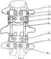
На фиг. 1 показано устройство в сборе; на фиг. 2 - схема чрескостного остеосинтеза позвоночника, вид сбоку; на фиг. 3 - схема чрескостного остеосинтеза позвоночника, вид сзади; на фиг. 4 - узел фиксации винта с цилиндрической головкой; на фиг. 5 - поперечная стяжка осевых стержней. In FIG. 1 shows a device assembly; in FIG. 2 is a side view of the transosseous spinal osteosynthesis; in FIG. 3 - diagram of transosseous osteosynthesis of the spine, rear view; in FIG. 4 - node fixing screw with a cylindrical head; in FIG. 5 - transverse screed axial rods.
Устройство для остеосинтеза позвоночника состоит из винтов 1 с цилиндрическими головками, корпусов держателей 2 с прорезью 3, осевыми 4 и шлицевыми отверстиями 5, держателей винтов 6 со сквозными отверстиями 7, вводимых в шлицевые отверстия 5 в корпусах 2, фиксирующих гаек 8, осевых стержней 9, вводимых в осевые отверстия 4 в корпусах 2, поперечных стяжек осевых стержней, состоящих из хомутов 10, перемычек 11, фиксирующих винтов 12. Основания хомутов 10 и одна из поверхностей перемычек 11, примыкающих к нему, выполнены зубчатыми. Цилиндрические головки винтов 1 для надежности фиксации снабжены лысками 13. The device for spinal osteosynthesis consists of
Предлагаемое устройство для остеосинтеза позвоночника используется следующим образом. The proposed device for osteosynthesis of the spine is used as follows.
Производят срединный линейный разрез кожи, подкожной клетчатки, поверхностной фасции. Тупым и острым путем выделяют поверхности остистых, суставных отростков и дужек на протяжении 3-5 позвонков. Под рентген-контролем через левые и правые корни дуг выше и ниже от поврежденного позвонка вводятся винты 1, осуществляют вправление перелома или смещения позвонков. Цилиндрические головки с лысками 13 проводятся в сквозные отверстия держателей 7. Держатели винтов 6 устанавливают в шлицевые отверстия 5 в корпусах 2. Осевые стержни 9 с предварительно установленными хомутами перемычек 10 проводятся в осевые отверстия 4 в корпусах держателей, при этом хомуты верхней стяжки располагаются ниже корпусов, а хомуты нижней выше. После адаптации узлов крепления и осевых стержней затягиваются фиксирующие гайки 8. На хомуты поперечных стяжек устанавливаются перемычки 11, причем при фиксации их винтами 12 зубчатые поверхности перемычек и оснований хомутов обращены друг к другу. Далее операционную рану ушивают. A midline linear incision is made of the skin, subcutaneous tissue, superficial fascia. The surfaces of the spinous, articular processes and arches over 3-5 vertebrae are blunt and sharp. Under x-ray control,
Использование предлагаемого изобретения по сравнению с прототипом позволит:
1. Повысить надежность фиксации оперированного отдела позвоночника, создать жесткую рамную конструкцию, препятствующую ротационным смещениям позвонков в послеоперационном периоде;
2. Использование в фиксирующих узлах поперечных стяжек хомутов позволяет уменьшить их размеры, что снижает травматизацию паравертебральных тканей, облегчает ведение больных в послеоперационном периоде.Using the proposed invention in comparison with the prototype will allow:
1. To increase the reliability of fixation of the operated spine, create a rigid frame structure that prevents rotational displacement of the vertebrae in the postoperative period;
2. The use of clamps in the fixing nodes of the transverse screeds makes it possible to reduce their size, which reduces the trauma of paravertebral tissues and facilitates the management of patients in the postoperative period.
Claims (1)
Translated fromRussianPriority Applications (1)
| Application Number | Priority Date | Filing Date | Title |
|---|---|---|---|
| RU99121462/14ARU2176907C2 (en) | 1999-10-13 | 1999-10-13 | Device for carrying out vertebral column osteosynthesis |
Applications Claiming Priority (1)
| Application Number | Priority Date | Filing Date | Title |
|---|---|---|---|
| RU99121462/14ARU2176907C2 (en) | 1999-10-13 | 1999-10-13 | Device for carrying out vertebral column osteosynthesis |
Publications (2)
| Publication Number | Publication Date |
|---|---|
| RU99121462A RU99121462A (en) | 2001-07-20 |
| RU2176907C2true RU2176907C2 (en) | 2001-12-20 |
Family
ID=20225753
Family Applications (1)
| Application Number | Title | Priority Date | Filing Date |
|---|---|---|---|
| RU99121462/14ARU2176907C2 (en) | 1999-10-13 | 1999-10-13 | Device for carrying out vertebral column osteosynthesis |
Country Status (1)
| Country | Link |
|---|---|
| RU (1) | RU2176907C2 (en) |
Cited By (6)
| Publication number | Priority date | Publication date | Assignee | Title |
|---|---|---|---|---|
| RU2234281C2 (en)* | 2002-03-19 | 2004-08-20 | Матюшин Александр Федорович | Device for making transverse connection of rods applied in performing instrumental vertebral column stabilization and axial deformity correction |
| RU2242188C2 (en)* | 2003-02-11 | 2004-12-20 | Государственное образовательное учреждение высшего профессионального образования Тюменский государственный нефтегазовый университет | Transpedicular fixing member |
| RU2249440C1 (en)* | 2003-07-11 | 2005-04-10 | Мухаметов Фарит Фагимович | Device for correcting and fixing the vertebral column |
| RU2301040C2 (en)* | 2003-12-19 | 2007-06-20 | Общество с ограниченной ответственностью "КОНМЕТ" | Spinal device preferably for tie pieces |
| RU2333731C1 (en)* | 2007-02-05 | 2008-09-20 | Федеральное государственное унитарное предприятие "Красноярский машиностроительный завод" ФГУП "Красмаш" | Fastener assembly of endodevice rod |
| RU2716347C1 (en)* | 2016-07-25 | 2020-03-11 | Поль ФАЯДА | Spinal stabilization device |
Citations (4)
| Publication number | Priority date | Publication date | Assignee | Title |
|---|---|---|---|---|
| SU806014A1 (en)* | 1978-02-15 | 1981-02-23 | Rublenik Ivan M | Compression fixative |
| SU1007659A1 (en)* | 1978-07-14 | 1983-03-30 | Rublenik Ivan M | Fixator for compression osteosynthesis |
| EP0355411A1 (en)* | 1988-08-10 | 1990-02-28 | Ace Medical Company | Intramedullary rod for femur stabilization |
| US5041114A (en)* | 1986-06-23 | 1991-08-20 | Pfizer Hospital Products Group, Inc. | Modular femoral fixation system |
- 1999
- 1999-10-13RURU99121462/14Apatent/RU2176907C2/ennot_activeIP Right Cessation
Patent Citations (4)
| Publication number | Priority date | Publication date | Assignee | Title |
|---|---|---|---|---|
| SU806014A1 (en)* | 1978-02-15 | 1981-02-23 | Rublenik Ivan M | Compression fixative |
| SU1007659A1 (en)* | 1978-07-14 | 1983-03-30 | Rublenik Ivan M | Fixator for compression osteosynthesis |
| US5041114A (en)* | 1986-06-23 | 1991-08-20 | Pfizer Hospital Products Group, Inc. | Modular femoral fixation system |
| EP0355411A1 (en)* | 1988-08-10 | 1990-02-28 | Ace Medical Company | Intramedullary rod for femur stabilization |
Cited By (6)
| Publication number | Priority date | Publication date | Assignee | Title |
|---|---|---|---|---|
| RU2234281C2 (en)* | 2002-03-19 | 2004-08-20 | Матюшин Александр Федорович | Device for making transverse connection of rods applied in performing instrumental vertebral column stabilization and axial deformity correction |
| RU2242188C2 (en)* | 2003-02-11 | 2004-12-20 | Государственное образовательное учреждение высшего профессионального образования Тюменский государственный нефтегазовый университет | Transpedicular fixing member |
| RU2249440C1 (en)* | 2003-07-11 | 2005-04-10 | Мухаметов Фарит Фагимович | Device for correcting and fixing the vertebral column |
| RU2301040C2 (en)* | 2003-12-19 | 2007-06-20 | Общество с ограниченной ответственностью "КОНМЕТ" | Spinal device preferably for tie pieces |
| RU2333731C1 (en)* | 2007-02-05 | 2008-09-20 | Федеральное государственное унитарное предприятие "Красноярский машиностроительный завод" ФГУП "Красмаш" | Fastener assembly of endodevice rod |
| RU2716347C1 (en)* | 2016-07-25 | 2020-03-11 | Поль ФАЯДА | Spinal stabilization device |
Similar Documents
| Publication | Publication Date | Title |
|---|---|---|
| EP1737369B1 (en) | Support for bone | |
| US7524323B2 (en) | Subcutaneous support | |
| US7648520B2 (en) | Pedicle screw assembly | |
| US20050228380A1 (en) | Instruments and methods for minimally invasive spine surgery | |
| US8834531B2 (en) | Method and system for trans-lamina spinal fixation | |
| US20020161367A1 (en) | Anatomic posterior lumbar plate | |
| US20060149252A1 (en) | Bone anchorage screw with built-in hinged plate | |
| WO1995022937A1 (en) | Angled bone fixation apparatus | |
| ZA200600577B (en) | Compounds for the treatment of metabolic disorders | |
| KR20050123111A (en) | Hybrid interlocking proximal femoral fracture fixation | |
| RU2176907C2 (en) | Device for carrying out vertebral column osteosynthesis | |
| RU2051633C1 (en) | Method and device for passing threaded bar into vertebra body | |
| RU2218122C1 (en) | Device for treating posterior spondylodesis | |
| US7833247B2 (en) | Orthopedic clamps | |
| RU2175859C2 (en) | Device for fixation of spinal column | |
| RU2321371C1 (en) | Reposition spinal column lock | |
| RU2160067C1 (en) | Device for performing posterior spondylodesis | |
| RU2726047C1 (en) | Method for intraoperative correction of spine scoliosis | |
| RU2131229C1 (en) | Osteosynthesis device | |
| CN115040223B (en) | A split steel plate end-fixed and clamped spinal canal shaping internal fixation device | |
| RU2127091C1 (en) | Device with set of instruments for correction of curvatures and stabilization of vertebral column segments | |
| RU2270632C1 (en) | Spinal column holder | |
| RU2219865C1 (en) | Device for stabilization of segments of spinal column | |
| RU2239392C2 (en) | Device for fixing the vertebral column | |
| UA35075A (en) | The device for the backbone fixation |
Legal Events
| Date | Code | Title | Description |
|---|---|---|---|
| MM4A | The patent is invalid due to non-payment of fees | Effective date:20041014 |