RU2175859C2 - Device for fixation of spinal column - Google Patents
Device for fixation of spinal columnDownload PDFInfo
- Publication number
- RU2175859C2 RU2175859C2RU2000102248ARU2000102248ARU2175859C2RU 2175859 C2RU2175859 C2RU 2175859C2RU 2000102248 ARU2000102248 ARU 2000102248ARU 2000102248 ARU2000102248 ARU 2000102248ARU 2175859 C2RU2175859 C2RU 2175859C2
- Authority
- RU
- Russia
- Prior art keywords
- holes
- fixation
- metal plate
- tenons
- aligned
- Prior art date
Links
- 229910052751metalInorganic materials0.000claimsabstractdescription14
- 239000002184metalSubstances0.000claimsabstractdescription14
- 230000006641stabilisationEffects0.000abstractdescription4
- 238000011105stabilizationMethods0.000abstractdescription4
- 230000000694effectsEffects0.000abstractdescription2
- 238000011477surgical interventionMethods0.000abstractdescription2
- 230000007721medicinal effectEffects0.000abstract1
- 239000000126substanceSubstances0.000abstract1
- 230000015572biosynthetic processEffects0.000description3
- 210000000988bone and boneAnatomy0.000description3
- 238000006073displacement reactionMethods0.000description3
- 238000009434installationMethods0.000description3
- 210000004446longitudinal ligamentAnatomy0.000description3
- 230000005012migrationEffects0.000description3
- 238000013508migrationMethods0.000description3
- 238000002271resectionMethods0.000description3
- 210000000278spinal cordAnatomy0.000description3
- 230000006837decompressionEffects0.000description2
- 230000007547defectEffects0.000description2
- 238000010586diagramMethods0.000description2
- 230000004927fusionEffects0.000description2
- 101800004660Aldosterone secretion inhibitory factorProteins0.000description1
- 206010011985Decubitus ulcerDiseases0.000description1
- 206010027677Fractures and dislocationsDiseases0.000description1
- 208000001132OsteoporosisDiseases0.000description1
- 208000004210Pressure UlcerDiseases0.000description1
- 206010041549Spinal cord compressionDiseases0.000description1
- RTAQQCXQSZGOHL-UHFFFAOYSA-NTitaniumChemical compound[Ti]RTAQQCXQSZGOHL-UHFFFAOYSA-N0.000description1
- 208000027418Wounds and injuryDiseases0.000description1
- 230000002411adverseEffects0.000description1
- 230000036770blood supplyEffects0.000description1
- 230000001054cortical effectEffects0.000description1
- 230000006378damageEffects0.000description1
- 210000003238esophagusAnatomy0.000description1
- 208000014674injuryDiseases0.000description1
- 230000003446memory effectEffects0.000description1
- 230000002887neurotoxic effectEffects0.000description1
- 230000008092positive effectEffects0.000description1
- 230000002980postoperative effectEffects0.000description1
- 238000004904shorteningMethods0.000description1
- 208000011580syndromic diseaseDiseases0.000description1
- 230000001225therapeutic effectEffects0.000description1
- 230000000451tissue damageEffects0.000description1
- 231100000827tissue damageToxicity0.000description1
- 239000010936titaniumSubstances0.000description1
- 229910052719titaniumInorganic materials0.000description1
- 231100000331toxicToxicity0.000description1
- 230000002588toxic effectEffects0.000description1
Images
Landscapes
- Surgical Instruments (AREA)
Abstract
Description
Translated fromRussianИзобретение относится к медицинской технике, а именно к устройствам для лечения повреждений шейного отдела позвоночника, и может быть использовано для фиксации и стабилизации позвонков (C3 - C7) при операциях переднего спондилодеза при переломах и вывихах шейных позвонков с синдромом компрессии спинного мозга. Область применения - нейрохирургия и травматология. The invention relates to medical equipment, and in particular to devices for treating injuries of the cervical spine, and can be used to fix and stabilize the vertebrae (C3 - C7) during operations of anterior spinal fusion for fractures and dislocations of the cervical vertebrae with spinal cord compression syndrome. Scope - neurosurgery and traumatology.
Известно устройство для фиксации шейного отдела позвоночника, состоящее из металлической пластины с отверстиями, которая крепится винтами к 4-5 позвонкам. Фиксирующие элементы - винты вводятся в тела позвонков до задней продольной связки через кортикальный слой заднего отдела тела позвонка (Элламаа А. Н. "Передний металлический спондилодез шейного отдела позвоночника". Вопросы нейрохирургии. 1985. N 5, с. 46-49). A device for fixing the cervical spine, consisting of a metal plate with holes, which is screwed to 4-5 vertebrae. Fixing elements - screws are inserted into the vertebral bodies up to the posterior longitudinal ligament through the cortical layer of the posterior vertebral body (A. Ellamaa, “Anterior metal spinal fusion of the cervical spine.” Neurosurgery issues. 1985. N 5, p. 46-49).
Недостатком данного устройства является опасность миграции фиксирующих винтов. Имеющиеся стандартные круглые отверстия не всегда позволяют установить винты в нужном положении. The disadvantage of this device is the risk of migration of fixing screws. The existing standard round holes do not always allow you to install the screws in the right position.
Известно устройство для стабилизации позвоночника (патент РФ N 2076656, МПК 6 A 61 F 2/44. 1997 г.), содержащее пластину металла с эффектом памяти формы в виде звезды с четным количеством остроконечных лучей, при этом четные лучи загнуты в одну сторону, а нечетные в другую. A device is known for stabilization of the spine (RF patent N 2076656, IPC 6 A 61 F 2/44. 1997), containing a metal plate with a shape memory effect in the form of a star with an even number of pointed rays, while the even rays are bent in one direction, and the odd ones to another.
Недостатком данного устройства является то, что использование этого устройства не предполагает резекцию тела позвонка, и делает невозможным переднюю декомпрессию спинного мозга. Кроме того, считается, что никелид титана обладает нейротоксическим свойством, что отрицательно сказывается на уже травмированный спинной мозг. The disadvantage of this device is that the use of this device does not imply a resection of the vertebral body, and makes anterior decompression of the spinal cord impossible. In addition, it is believed that titanium nickelide has a neurotoxic property, which adversely affects an already injured spinal cord.
Известен внутренний фиксатор позвоночника (Патент РФ N 2097007, МПК6 A 61 F 2/44, 1997 г.), содержащий фиксатор с внутренним цилиндрическим отверстием, наружная поверхность которого имеет конусообразную форму и снабжена глубокой винтовой резьбой и наружным тубусом для датчиков инструментального наблюдения, выполненным с возможностью установки во внутреннем цилиндрическом отверстии фиксатора, при этом во внутреннем цилиндрическом отверстии выполнены четыре продольных паза.Known internal retainer of the spine (RF Patent N 2097007, IPC6 A 61
Недостаток этого устройства - использование металлических конструкций без аутокости, применение этого устройства требует в последующем повторной операции для замещения дефекта кости. The disadvantage of this device is the use of metal structures without autobone, the use of this device requires subsequent re-operation to replace the bone defect.
Известно устройство AO/ASIF, состоящее из металлической пластины Н-образной формы и фиксирующих винтов, где для предотвращения возможной их миграции и смещения используются дополнительные стопорные винты, вводимые в основные фиксирующие (Мюллер М.Е., Алльговер М., Шнейдер Р., Виллингер Х. Руководство по внутреннему остеосинтезу. - 3-е издание, Springer-Verlag, 1996. - С. 653-655). AO / ASIF device is known, consisting of an H-shaped metal plate and fixing screws, where additional locking screws inserted into the main fixing screws are used to prevent their possible migration and displacement (Muller M.E., Allgover M., Schneider R., Willinger H. Guide to Internal Osteosynthesis. - 3rd edition, Springer-Verlag, 1996. - S. 653-655).
Недостатком данного устройства является то, что используемые металлические винты для фиксации вводятся в тела смежных позвонков двумя рядами, тем самым грубо нарушают кровоснабжение тел позвонков в микроциркуляторном русле, что в дальнейшем приводит к развитию остеопороза и возможной нестабильности. The disadvantage of this device is that the used metal screws for fixation are inserted into the bodies of adjacent vertebrae in two rows, thereby roughly violating the blood supply to the vertebral bodies in the microvasculature, which subsequently leads to the development of osteoporosis and possible instability.
Наиболее близким по технической сущности и достигаемому результату к заявляемому является устройство для фиксации позвоночника фирмы "Aesculap", представляющее собой металлическую пластину с двумя рядами отверстий и двумя шипами, фиксирующие элементы которой - металлические винты (Aesculap, Scientific Information N 12, 1986 г., p. 55, FF 980S-FF995 S, Germ. Fed. Regd. Des. German Patent, Japan Patent N 1383842, US Patent N 4503848). The closest in technical essence and the achieved result to the claimed is a device for fixing the spine of the company "Aesculap", which is a metal plate with two rows of holes and two spikes, the fixing elements of which are metal screws (Aesculap, Scientific Information N 12, 1986, p. 55, FF 980S-FF995 S, Germ. Fed. Reg. Des. German Patent, Japan Patent N 1383842, US Patent N 4503848).
Однако использование этого устройства, в частности винтов, не обеспечивает надежной стабилизации из-за возможной их миграции (Aesculap, Scientific Information N 12, 1986 г., p. 26, Fig. 35 a). Смещения винтов в сторону пищевода в послеоперационном периоде может привести к образованию пролежней на нем. В случае обширной резекции тела позвонка применение данного устройства предполагает фиксацию трансплантата дополнительно введенными в него винтами, что не всегда благоприятствует быстрому образованию костного блока. However, the use of this device, in particular screws, does not provide reliable stabilization due to their possible migration (Aesculap, Scientific Information No. 12, 1986, p. 26, Fig. 35 a). Displacement of the screws towards the esophagus in the postoperative period can lead to the formation of pressure sores on it. In the case of extensive resection of the vertebral body, the use of this device involves fixing the graft with additional screws inserted into it, which does not always favor the rapid formation of a bone block.
Задачей изобретения является повышение лечебного эффекта путем уменьшения травматичности операции за счет уменьшения количества ее этапов, сокращения необходимого инструментария и укорочения времени оперативного вмешательства, дополнительной передней декомпрессии спинного мозга, а также повышение степени надежности фиксации трансплантата. The objective of the invention is to increase the therapeutic effect by reducing the invasiveness of the operation by reducing the number of stages, reducing the necessary tools and shortening the time of surgical intervention, additional anterior decompression of the spinal cord, as well as increasing the degree of reliability of fixation of the graft.
Поставленная задача достигается тем, что в устройстве для фиксации позвоночника, содержащем прижимную металлическую пластину с одним рядом продольных отверстий, соосными шипами, в отличие от прототипа фиксирующие элементы выполнены в виде двух Г-образных пластин, каждая из которых снабжена двумя соосными шипами, винтовым стержнем, на котором имеется продольный паз и стопорная гайка. This object is achieved in that in the device for fixing the spine, containing a clamping metal plate with one row of longitudinal holes, coaxial spikes, unlike the prototype, the locking elements are made in the form of two L-shaped plates, each of which is equipped with two coaxial spikes, a screw shaft on which there is a longitudinal groove and a lock nut.
Сущность устройства поясняется чертежами. The essence of the device is illustrated by drawings.
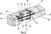
На фиг. 1 показана схема устройства. На фиг. 2 показана схема установки фиксатора позвоночника. In FIG. 1 shows a diagram of a device. In FIG. 2 shows the installation diagram of the spine retainer.
Устройство состоит из металлической пластины 1 с одним рядом продольных щелевидных отверстий 2, снабженной двумя шипами 3, и двух фиксирующих элементов Г-образной формы 4, снабженных двумя шипами 5 и винтовым стержнем 6, на котором имеется продольный паз 7 и стопорная гайка 8. The device consists of a metal plate 1 with one row of longitudinal slit-
Устройство применяется следующим образом. The device is used as follows.
После доступа к передней поверхности тел шейных позвонков производят резекцию тела поврежденного позвонка при помощи корончатой фрезы до задней продольной связки. Затем из крыла подвздошной кости выпиливают трансплантат 9, больший по диаметру на 1-2 мм. Фиксирующие элементы 4 устанавливают в образовавшийся дефект краниально и каудально, соблюдая соосность. Шипы 5 погружают в тела смежных позвонков. Трансплантат 9 устанавливают на место резецированного тела позвонка. Металлическую пластину 1 накладывают на переднюю поверхность тел смежных позвонков так, чтобы винтовые стержни 6 вошли в имеющиеся продольные щелевидные отверстия 2, затем стопорной гайкой 8 производят прижимание пластины 1 к передней продольной связке и трансплантату 9 до погружения шипов 3 в тела позвонков. После установки пластины производят стопорение гайки за счет разведения концов винтового стержня 6 в области паза 7. Поочередно сверху и снизу выступающие концы винтовых стержней скусывают резаком. After access to the front surface of the cervical vertebrae, a resection of the body of the damaged vertebra is performed using a crown cutter to the posterior longitudinal ligament. Then, graft 9, larger in diameter by 1-2 mm, is cut out from the iliac wing. The fixing elements 4 are installed in the resulting defect cranially and caudally, observing alignment. Spikes 5 are immersed in adjacent vertebral bodies. The graft 9 is installed in place of the resected vertebral body. A metal plate 1 is placed on the front surface of adjacent vertebral bodies so that the
Применение данного устройства обеспечивает надежную стабилизацию позвоночника, использование трансплантата из аутокости предотвращает токсическое поражение тканей, способствует быстрому образованию костного блока, предотвращает смещение трансплантата, использование шипов уменьшает воздействие металлоконструкций на микроциркуляторное русло в телах позвонков, чем достигается положительный эффект по сравнению с аналогами. The use of this device ensures reliable stabilization of the spine, the use of an autobone graft prevents toxic tissue damage, promotes rapid bone block formation, prevents graft displacement, the use of spikes reduces the effect of metal structures on the microvasculature in the vertebral bodies, thereby achieving a positive effect compared to analogues.
Claims (1)
Translated fromRussianPriority Applications (1)
| Application Number | Priority Date | Filing Date | Title |
|---|---|---|---|
| RU2000102248ARU2175859C2 (en) | 2000-01-28 | 2000-01-28 | Device for fixation of spinal column |
Applications Claiming Priority (1)
| Application Number | Priority Date | Filing Date | Title |
|---|---|---|---|
| RU2000102248ARU2175859C2 (en) | 2000-01-28 | 2000-01-28 | Device for fixation of spinal column |
Publications (2)
| Publication Number | Publication Date |
|---|---|
| RU2175859C2true RU2175859C2 (en) | 2001-11-20 |
| RU2000102248A RU2000102248A (en) | 2001-12-27 |
Family
ID=20229971
Family Applications (1)
| Application Number | Title | Priority Date | Filing Date |
|---|---|---|---|
| RU2000102248ARU2175859C2 (en) | 2000-01-28 | 2000-01-28 | Device for fixation of spinal column |
Country Status (1)
| Country | Link |
|---|---|
| RU (1) | RU2175859C2 (en) |
Cited By (5)
| Publication number | Priority date | Publication date | Assignee | Title |
|---|---|---|---|---|
| RU2202298C2 (en)* | 2001-06-09 | 2003-04-20 | Закрытое акционерное общество "КОНМЕТ Инкорпорейтед" | Surgical method and device for treating degenerative vertebral column diseases |
| RU2229271C1 (en)* | 2002-09-09 | 2004-05-27 | Государственное федеральное учреждение науки Уральский научно-исследовательский институт травматологии и ортопедии им. В.Д. Чаклина | Method and device for treating the cases of retrospondylolisthesis |
| RU2282422C2 (en)* | 2002-03-12 | 2006-08-27 | Сервитек Инк. | Cervical intervertebral prosthesis |
| RU2299045C2 (en)* | 2005-07-05 | 2007-05-20 | Федеральное государственное учреждение Новосибирский научно-исследовательский институт травматологии и ортопедии (ФГУ ННИИТО Росздрава) | Endoclamp plate for fixing cervical segment of the vertebral column |
| RU2343878C2 (en)* | 2004-08-17 | 2009-01-20 | Тимур Булатович Минасов | Device for interbody bracing of vertebra |
Citations (3)
| Publication number | Priority date | Publication date | Assignee | Title |
|---|---|---|---|---|
| SU1591973A1 (en)* | 1987-12-21 | 1990-09-15 | Sibirsk Fiz Tekh Inst | Vertebra body prosthesis |
| SU1653764A1 (en)* | 1989-06-19 | 1991-06-07 | Научно-Производственное Объединение "Монокристаллреактив" | Vertebra body endoprosthesis |
| RU2080841C1 (en)* | 1993-06-28 | 1997-06-10 | Частное предприятие "Алекс" | Intervertebral disk endoprosthesis |
- 2000
- 2000-01-28RURU2000102248Apatent/RU2175859C2/enactive
Patent Citations (3)
| Publication number | Priority date | Publication date | Assignee | Title |
|---|---|---|---|---|
| SU1591973A1 (en)* | 1987-12-21 | 1990-09-15 | Sibirsk Fiz Tekh Inst | Vertebra body prosthesis |
| SU1653764A1 (en)* | 1989-06-19 | 1991-06-07 | Научно-Производственное Объединение "Монокристаллреактив" | Vertebra body endoprosthesis |
| RU2080841C1 (en)* | 1993-06-28 | 1997-06-10 | Частное предприятие "Алекс" | Intervertebral disk endoprosthesis |
Cited By (5)
| Publication number | Priority date | Publication date | Assignee | Title |
|---|---|---|---|---|
| RU2202298C2 (en)* | 2001-06-09 | 2003-04-20 | Закрытое акционерное общество "КОНМЕТ Инкорпорейтед" | Surgical method and device for treating degenerative vertebral column diseases |
| RU2282422C2 (en)* | 2002-03-12 | 2006-08-27 | Сервитек Инк. | Cervical intervertebral prosthesis |
| RU2229271C1 (en)* | 2002-09-09 | 2004-05-27 | Государственное федеральное учреждение науки Уральский научно-исследовательский институт травматологии и ортопедии им. В.Д. Чаклина | Method and device for treating the cases of retrospondylolisthesis |
| RU2343878C2 (en)* | 2004-08-17 | 2009-01-20 | Тимур Булатович Минасов | Device for interbody bracing of vertebra |
| RU2299045C2 (en)* | 2005-07-05 | 2007-05-20 | Федеральное государственное учреждение Новосибирский научно-исследовательский институт травматологии и ортопедии (ФГУ ННИИТО Росздрава) | Endoclamp plate for fixing cervical segment of the vertebral column |
Similar Documents
| Publication | Publication Date | Title |
|---|---|---|
| US10076368B2 (en) | Medial-plantar plate for medial column arthrodesis | |
| EP2341874B1 (en) | Foot, ankle, and lower extremity compression and fixation system | |
| JP3236938B2 (en) | Adhesion stabilization chamber | |
| US9451986B2 (en) | Percutaneous sacroiliac joint implant and method for surgically inserting and securing the implant into the sacroiliac joint | |
| US7789899B2 (en) | Bone anchorage screw with built-in hinged plate | |
| AU2014321174A1 (en) | Medial-plantar plate for medial column arthrodesis | |
| Moftakhar et al. | Anterior cervical plates: a historical perspective | |
| KR20070020035A (en) | Bone support | |
| Kim et al. | A biomechanical comparison of three surgical approaches in bilateral subaxial cervical facet dislocation | |
| RU2485904C1 (en) | Method of monosegmental transpedicular stabilisation of fractures of lower thoracic and lumbar vertebrae bodies | |
| RU2175859C2 (en) | Device for fixation of spinal column | |
| RU2289351C2 (en) | Intramedullary pin for performing trochanteric femur fracture osteosynthesis | |
| RU2444316C2 (en) | Method of intra-operative reduction of sliding-off vertebra | |
| RU2218122C1 (en) | Device for treating posterior spondylodesis | |
| US7833247B2 (en) | Orthopedic clamps | |
| RU2176907C2 (en) | Device for carrying out vertebral column osteosynthesis | |
| RU2467715C1 (en) | Method for stabilising vertebral body fractures complicated by osteoporosis | |
| RU2392888C1 (en) | Staging surgical correction of spine deformation | |
| RU2577940C2 (en) | Method for percoetaneous transpedicular stabilisation of thoracic and lumbar spine | |
| RU2056804C1 (en) | Rod apparatus for extra-articular arthrodesis of hip joint | |
| RU2239392C2 (en) | Device for fixing the vertebral column | |
| Grady et al. | Lateral mass plate stabilization of the cervical spine | |
| Voss | The Compact UniLock 2.0/2.4 TM system for ventral stabilization of the cervical spine. | |
| RU80334U1 (en) | DEVICE FOR OSTEOSYNTHESIS | |
| El-Meshtawy et al. | Safety and Efficacy of Percutaneous Non-Canulated Transpedicular Screws Fixation (TPSF) in the Management of Thoracolumbar Fractures |