RU2172187C2 - Intravenous catheter with self-adjusting needle protecting device - Google Patents
Intravenous catheter with self-adjusting needle protecting deviceDownload PDFInfo
- Publication number
- RU2172187C2 RU2172187C2RU96111011/14ARU96111011ARU2172187C2RU 2172187 C2RU2172187 C2RU 2172187C2RU 96111011/14 ARU96111011/14 ARU 96111011/14ARU 96111011 ARU96111011 ARU 96111011ARU 2172187 C2RU2172187 C2RU 2172187C2
- Authority
- RU
- Russia
- Prior art keywords
- needle
- catheter
- deformed
- circular
- sleeve
- Prior art date
Links
- 238000001990intravenous administrationMethods0.000titleclaimsdescription17
- 230000001012protectorEffects0.000claimsdescription30
- 230000001681protective effectEffects0.000claimsdescription18
- 238000003780insertionMethods0.000claimsdescription4
- 230000037431insertionEffects0.000claimsdescription4
- 239000003814drugSubstances0.000abstractdescription6
- 239000000126substanceSubstances0.000abstractdescription2
- 238000010276constructionMethods0.000abstract2
- 230000008878couplingEffects0.000abstract1
- 238000010168coupling processMethods0.000abstract1
- 238000005859coupling reactionMethods0.000abstract1
- 230000000694effectsEffects0.000abstract1
- 210000003462veinAnatomy0.000description17
- 239000012530fluidSubstances0.000description5
- 239000008280bloodSubstances0.000description4
- 210000004369bloodAnatomy0.000description4
- 229940079593drugDrugs0.000description4
- 208000015181infectious diseaseDiseases0.000description4
- 238000002347injectionMethods0.000description4
- 239000007924injectionSubstances0.000description4
- 239000007788liquidSubstances0.000description4
- 238000000034methodMethods0.000description4
- 208000012260Accidental injuryDiseases0.000description3
- 208000014674injuryDiseases0.000description3
- 208000027418Wounds and injuryDiseases0.000description2
- 210000001367arteryAnatomy0.000description2
- 238000009534blood testMethods0.000description2
- 229920006335epoxy gluePolymers0.000description2
- 239000003978infusion fluidSubstances0.000description2
- 239000007787solidSubstances0.000description2
- 208000030507AIDSDiseases0.000description1
- 208000034656ContusionsDiseases0.000description1
- 239000004812Fluorinated ethylene propyleneSubstances0.000description1
- 241000725303Human immunodeficiency virusSpecies0.000description1
- 206010052428WoundDiseases0.000description1
- 230000005540biological transmissionEffects0.000description1
- 210000004204blood vesselAnatomy0.000description1
- 210000000748cardiovascular systemAnatomy0.000description1
- 230000006378damageEffects0.000description1
- 229920006332epoxy adhesivePolymers0.000description1
- HQQADJVZYDDRJT-UHFFFAOYSA-Nethene;prop-1-eneChemical groupC=C.CC=CHQQADJVZYDDRJT-UHFFFAOYSA-N0.000description1
- 208000006454hepatitisDiseases0.000description1
- 231100000283hepatitisToxicity0.000description1
- 238000010253intravenous injectionMethods0.000description1
- 239000000463materialSubstances0.000description1
- 239000012528membraneSubstances0.000description1
- 229920009441perflouroethylene propylenePolymers0.000description1
- 230000002093peripheral effectEffects0.000description1
- 239000004814polyurethaneSubstances0.000description1
- 229920002635polyurethanePolymers0.000description1
- 239000011343solid materialSubstances0.000description1
- 230000008733traumaEffects0.000description1
Images


Classifications
- A—HUMAN NECESSITIES
- A61—MEDICAL OR VETERINARY SCIENCE; HYGIENE
- A61M—DEVICES FOR INTRODUCING MEDIA INTO, OR ONTO, THE BODY; DEVICES FOR TRANSDUCING BODY MEDIA OR FOR TAKING MEDIA FROM THE BODY; DEVICES FOR PRODUCING OR ENDING SLEEP OR STUPOR
- A61M25/00—Catheters; Hollow probes
- A61M25/01—Introducing, guiding, advancing, emplacing or holding catheters
- A61M25/06—Body-piercing guide needles or the like
- A61M25/0612—Devices for protecting the needle; Devices to help insertion of the needle, e.g. wings or holders
- A61M25/0618—Devices for protecting the needle; Devices to help insertion of the needle, e.g. wings or holders having means for protecting only the distal tip of the needle, e.g. a needle guard
- A—HUMAN NECESSITIES
- A61—MEDICAL OR VETERINARY SCIENCE; HYGIENE
- A61M—DEVICES FOR INTRODUCING MEDIA INTO, OR ONTO, THE BODY; DEVICES FOR TRANSDUCING BODY MEDIA OR FOR TAKING MEDIA FROM THE BODY; DEVICES FOR PRODUCING OR ENDING SLEEP OR STUPOR
- A61M25/00—Catheters; Hollow probes
- A—HUMAN NECESSITIES
- A61—MEDICAL OR VETERINARY SCIENCE; HYGIENE
- A61M—DEVICES FOR INTRODUCING MEDIA INTO, OR ONTO, THE BODY; DEVICES FOR TRANSDUCING BODY MEDIA OR FOR TAKING MEDIA FROM THE BODY; DEVICES FOR PRODUCING OR ENDING SLEEP OR STUPOR
- A61M5/00—Devices for bringing media into the body in a subcutaneous, intra-vascular or intramuscular way; Accessories therefor, e.g. filling or cleaning devices, arm-rests
- A61M5/178—Syringes
- A61M5/31—Details
- A61M5/32—Needles; Details of needles pertaining to their connection with syringe or hub; Accessories for bringing the needle into, or holding the needle on, the body; Devices for protection of needles
- A61M5/3205—Apparatus for removing or disposing of used needles or syringes, e.g. containers; Means for protection against accidental injuries from used needles
- A61M5/321—Means for protection against accidental injuries by used needles
- A61M5/3243—Means for protection against accidental injuries by used needles being axially-extensible, e.g. protective sleeves coaxially slidable on the syringe barrel
- A61M5/3273—Means for protection against accidental injuries by used needles being axially-extensible, e.g. protective sleeves coaxially slidable on the syringe barrel freely sliding on needle shaft without connection to syringe or needle
- A—HUMAN NECESSITIES
- A61—MEDICAL OR VETERINARY SCIENCE; HYGIENE
- A61M—DEVICES FOR INTRODUCING MEDIA INTO, OR ONTO, THE BODY; DEVICES FOR TRANSDUCING BODY MEDIA OR FOR TAKING MEDIA FROM THE BODY; DEVICES FOR PRODUCING OR ENDING SLEEP OR STUPOR
- A61M5/00—Devices for bringing media into the body in a subcutaneous, intra-vascular or intramuscular way; Accessories therefor, e.g. filling or cleaning devices, arm-rests
- A61M5/178—Syringes
- A61M5/31—Details
- A61M5/32—Needles; Details of needles pertaining to their connection with syringe or hub; Accessories for bringing the needle into, or holding the needle on, the body; Devices for protection of needles
- A61M5/3205—Apparatus for removing or disposing of used needles or syringes, e.g. containers; Means for protection against accidental injuries from used needles
- A61M5/321—Means for protection against accidental injuries by used needles
- A61M5/3243—Means for protection against accidental injuries by used needles being axially-extensible, e.g. protective sleeves coaxially slidable on the syringe barrel
- A61M5/3245—Constructional features thereof, e.g. to improve manipulation or functioning
- A61M2005/3247—Means to impede repositioning of protection sleeve from needle covering to needle uncovering position
- A61M2005/325—Means obstructing the needle passage at distal end of a needle protection sleeve
Landscapes
- Health & Medical Sciences (AREA)
- Life Sciences & Earth Sciences (AREA)
- Engineering & Computer Science (AREA)
- Hematology (AREA)
- General Health & Medical Sciences (AREA)
- Anesthesiology (AREA)
- Biomedical Technology (AREA)
- Heart & Thoracic Surgery (AREA)
- Veterinary Medicine (AREA)
- Animal Behavior & Ethology (AREA)
- Public Health (AREA)
- Pulmonology (AREA)
- Biophysics (AREA)
- Environmental & Geological Engineering (AREA)
- Vascular Medicine (AREA)
- Infusion, Injection, And Reservoir Apparatuses (AREA)
- Media Introduction/Drainage Providing Device (AREA)
Abstract
Description
Translated fromRussianНастоящее изобретение относится, в общем случае, к защитным закрывающим оболочкам внутривенных игл и, в частности, имеет отношение к защитным закрывающим оболочкам внутривенных игл, которые закрывают острие иглы после ее использования для предотвращения случайных ранений использованными иглами. The present invention relates, in general, to the protective closure sheaths of intravenous needles and, in particular, relates to the protective closure sheaths of intravenous needles that cover the tip of the needle after use to prevent accidental injuries by used needles.
Настоящее изобретение относится к клиническим устройствам, в которых используются острые иглы для пункции кожи пациента и, в частности, к катетерам, использующим такие иглы для выполнения пункций вены. The present invention relates to clinical devices that use sharp needles to puncture a patient’s skin and, in particular, to catheters using such needles to puncture a vein.
Среди врачей широко распространена практика инъекций жидкостей и лекарств непосредственно в кровеносную систему пациентов. Кроме того, во время хирургических операций часто необходимо производить полное переливание крови, а также вводить жидкости внутривенно. Исторически введение таких жидкостей в сердечно-сосудистую систему пациента требовало выполнения пункций вены с помощью полой твердой иглы, соединенной с источником внутривенной жидкости и т.п. Этот метод ввода жидких лекарств создавал ряд неизбежных и широко известных проблем. Прежде всего то обстоятельство, что игла, изготовленная из твердого материала, находится внутри вены, требует, чтобы игла, из соображений безопасности, закреплялась обычно на руке в фиксированном положении, в целом, в районе пункции вены в течение всего времени процедуры ввода жидких лекарств или переливания крови, что может занимать значительный период времени. Во-вторых, в случае необходимости периодического взятия анализов крови и/или последовательного внутривенного ввода жидких лекарств может быть необходимым каждый раз производить пункции вены, причем эти повторяющиеся пункции вены представляют для пациентов довольно значительную травму. The practice of injecting fluids and drugs directly into the circulatory system of patients is widespread among doctors. In addition, during surgical operations, it is often necessary to perform a complete blood transfusion, as well as inject fluids intravenously. Historically, the introduction of such fluids into the patient's cardiovascular system required puncture of a vein using a hollow solid needle connected to a source of intravenous fluid, etc. This method of injecting liquid drugs has created a number of inevitable and well-known problems. First of all, the fact that the needle, made of solid material, is inside the vein, requires that the needle, for safety reasons, is usually fixed on the arm in a fixed position, in general, in the area of the puncture of the vein during the entire duration of the procedure for introducing liquid drugs or blood transfusion, which can take a considerable period of time. Secondly, if it is necessary to periodically take blood tests and / or sequential intravenous injection of liquid drugs, it may be necessary to perform venous punctures each time, and these repeated puncture veins represent a rather significant trauma for patients.
Позже стал практиковаться ввод гибкой катетерной трубки в вену с тем, чтобы оставлять эту катетерную трубку в таком положении с целью периодического ввода жидкого лекарства, переливания крови и лечения, сбора анализов крови, и т.д. Таким образом, устранялись травмирование, кровоподтеки, поступление посторонних веществ и т.д., вызываемые повторяющимися пункциями вены, и была преодолена опасность и дискомфорт, связанные с нахождением твердой иглы в теле в течение длительного периода времени. Для того чтобы разместить конец такой гибкой катетерной трубки внутри полости человеческого тела, как, например, в кровеносном сосуде, используется полая игла для того, чтобы произвести пункцию вены. Затем после пункции вены катетерная трубка, которая установлена телескопически относительно иглы, смещается по отношению к игле и вводится в вену пациента. Иглу затем можно полностью извлечь из катетерной трубки и выбросить. После того как игла побывает в теле пациента, где она может быть инфицирована, она представляет опасность заражения персонала клиники, если кто-либо случайно уколется ею непосредственно после извлечения из тела пациента. Later, the introduction of a flexible catheter tube into a vein began to be practiced in order to leave this catheter tube in this position for the purpose of periodically injecting liquid medicine, blood transfusion and treatment, collecting blood tests, etc. Thus, injuries, bruises, foreign substances, etc., caused by repeated puncture of a vein, were eliminated, and the danger and discomfort associated with finding a solid needle in the body for a long period of time were overcome. In order to place the end of such a flexible catheter tube inside the cavity of the human body, such as in a blood vessel, a hollow needle is used to puncture a vein. Then, after the puncture of the vein, the catheter tube, which is mounted telescopically relative to the needle, is displaced with respect to the needle and inserted into the patient's vein. The needle can then be completely removed from the catheter tube and discarded. After the needle enters the patient’s body where it can be infected, it poses a risk of infection to the clinic staff if someone accidentally pricks it directly after removing it from the patient’s body.
Внутривенные катетеры для ввода жидкостей в периферийные вены пациента часто изготавливаются в двух формах: катетеры, помещаемые внутри иглы, в которых катетер проходит через игольчатую канюлю и вводится, таким образом, в вену пациента, и катетеры, помещенные поверх иглы, в которых игла и расположенный внешний концентрический катетер вводится в вену, и затем игла удаляется из установленного внутри вены катетера. Intravenous catheters for introducing fluids into the peripheral veins of a patient are often made in two forms: catheters placed inside the needle, in which the catheter passes through the needle cannula and inserted into the patient’s vein, and catheters placed on top of the needle, in which the needle and the located an external concentric catheter is inserted into the vein, and then the needle is removed from the catheter installed inside the vein.
Обычно в случае применения внутривенного катетера, расположенного поверх иглы, пользователь должен удалить и затем выбросить загрязненную иглу после того, как острие иглы и катетер правильным образом вводятся в вену пациента. Когда игла удаляется из катетера, пользователь обычно занят операциями, имеющими первоочередной приоритет, такими как подключение жидкостей для вливания в кровь, а также обработка раны, включая необходимость прикрепления катетера к телу пациента. Из-за безотлагательности этих процедур иглу обычно просто бросают в удобном месте поблизости и возвращаются к ней позже. Так как игла в это время находится поблизости к тому месту, где пользователь выполняет работу с катетером, случайные ранения такой иглой являются обычным явлением. Typically, if an intravenous catheter is placed on top of the needle, the user must remove and then discard the contaminated needle after the needle tip and catheter are correctly inserted into the patient's vein. When the needle is removed from the catheter, the user is usually busy with operations that have priority, such as connecting fluids to the bloodstream, as well as treating the wound, including the need to attach the catheter to the patient’s body. Due to the urgency of these procedures, the needle is usually simply thrown in a convenient place nearby and returned to it later. Since the needle at this time is close to the place where the user is working with the catheter, accidental injuries with such a needle are common.
В последнее время серьезно рассматривается возможность заражения персонала клиники вирусом СПИДа или гепатита из-за случайных пункций использованными иглами. В соответствии с этим для предотвращения таких случайных уколов было разработано значительное количество известных устройств. В настоящее время, поскольку существует серьезная опасность заражения персонала клиник из-за случайных уколов, включая возможность заражения СПИДом, стало еще более важным обеспечить механизм безопасности, который предлагает такому персоналу безотказную защиту, то есть устройство, которое действует без необходимости проведения осознанных подготовительных операций над его частями, механизм, который автоматически защищал бы острый конец иглы с момента, когда она извлекается из тела пациента. Recently, the possibility of infection of the clinic staff with the AIDS virus or hepatitis due to random punctures with used needles has been seriously considered. Accordingly, a significant number of known devices have been developed to prevent such accidental injections. Nowadays, since there is a serious risk of infection of clinic personnel due to accidental injections, including the possibility of contracting AIDS, it has become even more important to provide a security mechanism that offers such personnel failure-free protection, that is, a device that operates without the need for conscious preparatory operations on parts thereof, a mechanism that would automatically protect the sharp end of the needle from the moment it is removed from the patient’s body.
Американский патент автора Лемье (Lemieux) 4952207 также рассматривает эту проблему и описывает внутривенный катетер, который защищает медицинский персонал от случайных уколов, которые могут привести к передаче опасных инфекций. Катетер вводится с помощью иглы, которая затем извлекается из тела пациента в защитный корпус иглы без выхода острия иглы во время этого процесса наружу. Этот защитный корпус иглы запирается после извлечения иглы из тела, а извлечение иглы из тела и ее запирание производится во время одного непрерывного движения. American patent author Lemieux (Lemieux) 4952207 also addresses this problem and describes an intravenous catheter that protects medical personnel from accidental injections that can lead to the transmission of dangerous infections. The catheter is inserted using a needle, which is then removed from the patient’s body into the needle’s protective body without the needle tip coming out during this process. This protective body of the needle is locked after the needle is removed from the body, and the needle is removed from the body and locked during one continuous movement.
Настоящее изобретение представляет улучшение патента Лемье, которое объясняется более подробно со ссылкой на фигуры 1 - 4. The present invention is an improvement of the Lemieux patent, which is explained in more detail with reference to figures 1 to 4.
Основной задачей настоящего изобретения является получение защитной закрывающей оболочки внутривенной иглы. The main objective of the present invention is to obtain a protective closing membrane of an intravenous needle.
Другой задачей настоящего изобретения является получение защитной закрывающей оболочки внутривенной иглы, которая гарантирует, что игла закрыта таким образом, что опасность случайных уколов полностью устраняется после ее извлечения из тела пациента. Желательно, чтобы игла была надежно защищена в небольшом защитном приспособлении, и в наибольшей степени предпочтительно, чтобы это защитное приспособление для иглы автоматически переводилось в положение, закрывающее острие иглы после извлечения иглы из тела пациента без какого-либо специального движения пользователя. Another objective of the present invention is to provide a protective closure cover for an intravenous needle, which ensures that the needle is closed so that the risk of accidental injections is completely eliminated after it is removed from the patient’s body. It is desirable that the needle be securely protected in a small protective device, and it is most preferred that this protective device for the needle automatically translates into a position that covers the tip of the needle after removing the needle from the patient’s body without any special movement of the user.
В соответствии с приведенным описанием настоящее изобретение относится к внутривенному катетеру с иглой, имеющей самоустанавливающееся защитное устройство. Внутривенный катетер содержит узел катетера, имеющий катетер, присоединенный к полой втулке катетера, а также узел вводящей иглы. Узел вводящей иглы содержит полую иглу с острием, расположенным на ее дальнем конце, причем эта игла закрепляется своим ближним концом на втулке иглы, дальний конец которой приспособлен для соединения с полой втулкой катетера. Игла имеет, по существу, круглую внешнюю поверхность, проходящую вдоль ее дальнего конца, и некруглую деформированную внешнюю поверхность на определенном расстоянии от ее дальнего конца для взаимодействия с защитным приспособлением иглы. Защитное приспособление иглы содержит дальнюю часть, имеющую продольную длину больше, чем данное расстояние, и ближнюю часть, имеющую такую же некруглую деформированную внешнюю поверхность, как и у иглы, для того чтобы некруглая деформированная часть иглы могла проходить через нее, но чтобы круглая часть дальнего конца не могла проходить сквозь него. Защитное приспособление иглы устанавливается с возможностью движения относительно иглы с одновременным извлечением иглы из катетера до тех пор, пока некруглая деформированная часть защитного приспособления иглы не дойдет до круглой дальней части иглы, причем в этом положении дальняя часть защитного приспособления иглы закрывает и защищает, таким образом, острие иглы. In accordance with the above description, the present invention relates to an intravenous catheter with a needle having a self-aligning protective device. An intravenous catheter comprises a catheter assembly having a catheter attached to a hollow catheter sleeve, as well as an insertion needle assembly. The insertion needle assembly comprises a hollow needle with a tip located at its distal end, this needle being fixed at its proximal end to the needle hub, the far end of which is adapted to connect to the hollow catheter hub. The needle has a substantially circular outer surface extending along its distal end, and a non-circular deformed outer surface at a certain distance from its distal end to interact with the needle guard. The needle guard includes a distal portion having a longitudinal length greater than a given distance, and a proximal portion having the same non-circular deformed outer surface as that of the needle, so that the non-circular deformed portion of the needle can pass through it, but so that the circular portion of the far end could not pass through it. The needle protector is mounted to move relative to the needle while simultaneously removing the needle from the catheter until the non-circular deformed portion of the needle protector reaches the round distal part of the needle, and in this position, the far part of the needle protector closes and protects, needle point.
Более детально, некруглая деформированная внешняя форма защитного приспособления иглы не дает ей поворачиваться, и это защитное приспособление иглы, кроме того, имеет запорный механизм задвижки, который входит в концевое отверстие иглы для предотвращения обратного движения защитного приспособления иглы в направлении к ближнему концу иглы, когда запорный механизм закрыт. Защелка содержит выступ, фиксирующий защитное приспособление иглы внутри полой втулки катетера, в то время как круглая часть трубки иглы установлена в положении внутри и выступает за пределы защитного приспособления иглы. Некруглое деформированное сечение может иметь овальную форму, или деформированную овальную форму, или любую подходящую некруглую форму, например деформированную внутрь. Дальняя часть защитного приспособления иглы, предпочтительно, включает цилиндрическую часть, имеющую внутренний диаметр несколько больше, чем внешний круглый диаметр указанной иглы. In more detail, the non-circular deformed outer shape of the needle protector prevents it from turning, and this needle protector also has a locking shutter mechanism that enters the needle end hole to prevent the needle protector from moving back toward the proximal end of the needle when locking mechanism is closed. The latch includes a protrusion that secures the needle guard inside the hollow sleeve of the catheter, while the round portion of the needle tube is positioned inside and extends beyond the needle guard. The non-circular deformed section may have an oval shape, or a deformed oval shape, or any suitable non-circular shape, for example, deformed inward. The distal portion of the needle guard preferably includes a cylindrical portion having an inner diameter slightly larger than the outer circular diameter of said needle.
Вышеописанные задачи и преимущества настоящего изобретения для защитной закрывающей оболочки иглы могут быть лучше поняты специалистами в данной области со ссылкой на нижеследующее детальное описание ряда предпочтительных вариантов изобретения, рассматриваемых вместе с прилагаемыми чертежами, на которых одноименные элементы обозначены идентичными номерами ссылок, на которых:
фигура 1 представляет поперечное сечение внутривенного катетера известного уровня техники, изготовленного с защитным приспособлением иглы, помещенным внутри втулки катетера;
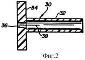
фигура 2 представляет защитное приспособление иглы в соответствии с фигурой 1 в поперечном сечении;
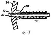
фигура 3 представляет защитное приспособление иглы, размещенное на ближнем конце иглы;
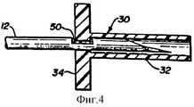
фигура 4 представляет защитное приспособление иглы, помещенное на дальнем конце иглы;
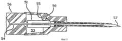
фигура 5 представляет защитное приспособление иглы, размещенное на втулке катетера, изготовленное в соответствии с описанием настоящего изобретения;
фигура 6 представляет защитное приспособление иглы в соответствии с фигурой 5, помещенное на ближнем конце иглы;
фигура 7 представляет защитное приспособление иглы в соответствии с фигурой 5, закрытое на дальнем конце иглы;
фигуры 8 и 9 являются поперечными сечениями по линии А - А фигуры 6, показывающие поперечное сечение различных вариантов осуществления трубки иглы.The above-described objects and advantages of the present invention for a protective needle cover may be better understood by those skilled in the art with reference to the following detailed description of a number of preferred embodiments of the invention, taken in conjunction with the accompanying drawings, in which like elements are denoted by the same reference numbers, on which:
Figure 1 is a cross-sectional view of a prior art intravenous catheter manufactured with a needle protector placed inside a catheter sleeve;
figure 2 is a needle guard in accordance with figure 1 in cross section;
figure 3 represents the needle guard located at the proximal end of the needle;
figure 4 represents the needle guard located at the far end of the needle;
Figure 5 represents a needle guard placed on a catheter sleeve made in accordance with the description of the present invention;
figure 6 represents the needle guard in accordance with figure 5, placed at the proximal end of the needle;
figure 7 represents the needle guard in accordance with figure 5, closed at the far end of the needle;
figures 8 and 9 are cross sections along line A - A of figure 6, showing a cross section of various embodiments of a needle tube.
Подробное описание чертежей
Ссылаясь на подробное описание чертежей, на фигуре 1 представлена конструкция катетера, изготовленного в соответствии с принципами американского патента автора Лемье 4952207. Катетер 10 включает трубку 15, изготовленную из фторированного этилен-пропилена или полиуретана. Трубка 15 заострена на ее дальнем конце 14, с помощью чего она может легко войти в отверстие в теле пациента, сформированном полой иглой 12. Ближний конец катетерной трубки 15 концентрически закреплен на дальнем конце катетерной втулки 16, 18, имеющей две части с различными диаметрами. Втулка, состоящая из двух частей различного диаметра, заканчивается на ее ближнем конце фиксатором или соединительным патрубком, приспособленным для подключения катетерной втулки к трубке капельницы, которая содержит емкость с внутривенной жидкостью. Катетер 10 соединен с полой иглой 12, которая соединена на ее ближнем конце с втулкой 20 иглы.Detailed Description of Drawings
Referring to the detailed description of the drawings, FIG. 1 shows the design of a catheter made in accordance with the principles of Lemieux U.S. Patent No. 4952207. Catheter 10 includes a tube 15 made of fluorinated ethylene propylene or polyurethane. The tube 15 is pointed at its distal end 14, whereby it can easily enter the hole in the patient’s body formed by the
Ближний конец катетера 15 закреплен внутри прохода 17 дальнего конца катетерной втулки 16 с помощью муфты 40. Муфта 40 расположена внутри ближнего конца полости катетера 15. Благодаря вводу муфты 40 внутрь полости катетера, эта муфта расширяет ближний конец катетера, прижимая его к внутренней поверхности прохода 17, соединяя, таким образом, втулку и катетер вместе для предотвращения их взаимного осевого движения. The proximal end of the catheter 15 is fixed inside the passage 17 of the far end of the catheter sleeve 16 with a sleeve 40. The sleeve 40 is located inside the proximal end of the catheter cavity 15. By introducing the sleeve 40 into the cavity of the catheter, this sleeve expands the proximal end of the catheter, pressing it against the inner surface of the passage 17 thus connecting the sleeve and the catheter together to prevent their mutual axial movement.
Полая игла 12 проходит от ее дальнего острия до катетера 15 и муфты 40, внутри прохода 27 по центру втулки 20 иглы. Ближний конец иглы 12 присоединен с помощью эпоксидного клея 24 к дальнему концу втулки 20 иглы. Ближний конец иглы 12 проходит через эпоксидный клей и через проход так, что полость иглы во время сборки не заполняется эпоксидным клеем. The
Дальний конец 28 втулки 20 иглы имеет меньший диаметр, чем большая часть втулки иглы. Этот конец с меньшим диаметром имеет такие размеры, чтобы входить в открытый ближний конец втулки 18 катетера. Защитное приспособление 30 острия иглы расположено внутри полости 22 втулки катетера. На фигуре 2 представлено увеличенное поперечное сечение защитного приспособления 30 острия иглы, которое напоминает цилиндр с фланцем. Цилиндрическая дальняя часть 32 защитного приспособления имеет внутреннее отверстие с диаметром, который позволяет части 32 гладко скользить вдоль иглы 12. Внутренний диаметр цилиндрической части 32 незначительно больше, чем наружный диаметр иглы. На ближнем конце защитного приспособления 30 имеется круглый запирающий фланец 34, центральное отверстие 36 которого является концентрическим с отверстием цилиндрической части 32. Диаметр отверстия 36 фланца незначительно меньше, чем наружный диаметр иглы 12. Фланец 34 и ближняя часть цилиндрической части 32 имеют продольный разрез, играющий роль разреза 38 горизонтального расширения. Защитное приспособление 30 острия иглы изготавливается из гибкого материала так, что фланец и цилиндрическая часть могут отгибаться в открытое и закрытое положение, как описано ниже. The distal end 28 of the needle sleeve 20 has a smaller diameter than most of the needle sleeve. This smaller diameter end is sized to fit into the open proximal end of the catheter sleeve 18. The
Ссылаясь одновременно на фигуры 1 и 3, представляющие узел в виде, когда катетер и вводящая игла собраны вместе перед использованием, защитное приспособление острия иглы пропущено через острие иглы и далее в положение недалеко от дальнего конца втулки 20 иглы. Так как отверстие 36 фланца немного меньше, чем наружный диаметр иглы, игла будет расширять защитное приспособление острия иглы в открытое положение вдоль разреза 38 расширения. Катетер и втулка катетера надеваются на иглу до тех пор, пока втулка 18 не соединится с дальним концом втулки иглы, как показано на фигуре 1. Защитное приспособление 30 острия иглы вследствие этого проходит внутрь полости 22 втулки катетера. Расширение фланца 34 заставляет верхнюю и нижнюю часть фланца войти в соединение с внутренними стенками втулки катетера, что показано позицией 39. Защитное приспособление острия иглы, таким образом, прижимается и удерживается внутри полости 22 втулки катетера. Для обеспечения прочного соединения защитного приспособления острия иглы внутри полости 22 может потребоваться выполнить выступы на внутренних стенках втулки катетера вблизи требуемого места размещения защитного приспособления, как отмечено позицией 44. Referring to both Figures 1 and 3, representing the assembly in the form when the catheter and insertion needle are assembled together before use, the needle tip protector is passed through the needle tip and then to a position near the far end of the needle sleeve 20. Since the
После того как пользователь введет в правильном положении острие иглы и дальний конец катетера внутрь артерии или вены пациента, что будет видно по появлению крови в устройстве быстрого подключения (не показано), игла и втулка иглы извлекаются из катетера для того, чтобы подготовить его к присоединению трубки к втулке катетера. При извлечении иглы, она скользит вдоль защитного приспособления 30 острия иглы, которое остается на своем месте внутри полости 22 из-за того, что оно зацепляется фланцем 34 с втулкой катетера в точке 39. Игла скользит вдоль защитного приспособления 30 острия иглы, как показано на фигуре 3. В конце этого движения игла извлекается до такого положения, что прорезь 50 зацепления, расположенная поблизости от острия иглы 12, доходит до фланца 34. В этот момент разрез 38 расширения защитного приспособления упруго закрывается, поскольку край отверстия 36 фланца входит в соединение с прорезью 50. Так как фланец в этом положении больше не является расширенным, он больше не удерживается внутри втулки катетера, а выходит из полости 22 в положении, соединенном с иглой 12 и прорезью зацепления 50, как показано на фигуре 4. Иглу можно затем спокойно отложить в сторону, при этом она не будет представлять опасности случайного ранения. After the user inserts the needle tip and the far end of the catheter into the patient’s artery or vein in the correct position, which will be visible by the appearance of blood in the quick-connect device (not shown), the needle and needle sleeve are removed from the catheter in order to prepare it for attachment tubes to the catheter sleeve. When the needle is removed, it slides along the
На фигуре 5 представлено сечение защитного приспособления 51 острия иглы, находящегося внутри полости 53 втулки 50 катетера. На фигуре 6 показано увеличенное поперечное сечение защитного приспособления 51 острия иглы, установленного на ближнем конце трубки 54 иглы с защелкой 52, удерживаемой в поднятом положении трубкой 54 иглы. На фигуре 5 защелка 52 находится в зацеплении с выступом 55, который не позволяет защитному приспособлению 51 острия иглы выйти из полости 53 до тех пор, пока защелка 52 установлена трубкой 54 иглы в поднятом положении. The figure 5 presents a cross section of the
Защитное приспособление 51 острия иглы имеет отверстие в ближнем конце, которое соответствует по форме деформированной части трубки 54 иглы, один из вариантов которой представлен на фигуре 8, что позволяет деформированной части 58 свободно проходить через это отверстие, но не позволяет проходить круглой, недеформированной части 59 иглы. Защитное приспособление 51 имеет отверстие на дальнем конце, длина которого больше, чем длина недеформированной части трубки 54 иглы, а форма и размер этого отверстия позволяет свободно проходить через него как деформированной, так и недеформированной частям трубки иглы. Форма отверстия и форма трубки иглы, как будет более подробно описано в дальнейшем, не позволяет острию иглы выйти из защитного приспособления. The
После того как пользователь правильно установит острие иглы и дальний конец катетера внутри артерии или вены пациента, игла 54 и втулка иглы 56 вынимаются из катетера. Во время вытаскивания иглы защитное приспособление 51 острия иглы удерживается внутри полости 53 с помощью защелки 52. Деформированная часть иглы 54 свободно проходит через защитное приспособление 51 острия иглы до тех пор, пока круглая дальняя часть иглы 54 не войдет и не установится внутри защитного приспособления 51 иглы, которое благодаря внутренней форме защитного приспособления 51 иглы, не позволяет пройти через него круглой части иглы 54, не давая дальнему концу трубки иглы 54 выйти из защитного приспособления 51 острия иглы. Как только круглая часть иглы 54 войдет в защитное приспособление 51 острия иглы, защелка 52 окажется расположенной непосредственно над отверстием 57 полости иглы, и больше не будет удерживаться поверхностью трубки 54 иглы, а перейдет в нижнее положение внутрь отверстия 57 полости иглы благодаря пружинящему давлению защелки 52. При ее переходе вниз происходит следующее: во-первых, защелка 52 будет препятствовать выходу трубке иглы в обратном направлении из защитного приспособления 51 острия иглы, удерживая, таким образом, острие иглы внутри, и во-вторых, защелка 52 выходит из зацепления с выступом 55, позволяя защитному приспособлению 51 острия иглы и защелке 52, которые теперь зафиксированы на дальнем конце трубки 54 иглы, выйти из полости 53, т.е. удалить их из втулки катетера. After the user correctly positions the needle tip and the distal end of the catheter inside the patient’s artery or vein, the
На фигуре 7 защелка 52 показана в положении, когда она входит в отверстие полости 57 иглы, при этом защитное приспособление 51 острия иглы находится на дальнем конце трубки 54 иглы. In figure 7, the
Фигуры 8 и 9 представляют собой поперечное сечение по линии А-А на фигуре 6, показывая поперечные сечения различных вариантов осуществления трубки иглы. В первом варианте, представленном на фигуре 8, трубка иглы имеет овальную деформированную форму 58 и круглую форму 59. Во втором варианте, представленном на фигуре 8, трубка иглы имеет деформированную внутрь форму 58' и круглую форму 59'. Figures 8 and 9 are a cross section along line AA in Figure 6, showing cross sections of various embodiments of a needle tube. In the first embodiment shown in FIG. 8, the needle tube has an oval
В целом, часть круглой трубки иглы деформирована с приданием ей овальной формы, (или деформирована с приданием другой формы), и внутренние размеры защитного приспособления иглы полностью соответствуют ей по форме и размерам, что позволяет защитному приспособлению скользить вдоль деформированной овальной части, но не позволяет передвигаться по круглой части. Такая конструкция не только не позволяет защитному приспособлению пройти за пределы дальнего конца иглы, но также не дает ему вращаться вокруг иглы, позволяя механизму защелки войти в зацепление с отверстием полости иглы для того, чтобы не дать защитному устройству выйти в обратном направлении к ближнему концу иглы. In general, a part of the round needle tube is deformed into an oval shape (or deformed into a different shape), and the inner dimensions of the needle protector fully correspond to it in shape and size, which allows the protector to slide along the deformed oval part, but does not allow move around the round part. This design not only prevents the protective device from extending beyond the far end of the needle, but also prevents it from rotating around the needle, allowing the latch mechanism to engage with the hole of the needle cavity so as to prevent the protective device from going back to the proximal end of the needle .
Хотя здесь были подробно описаны несколько вариантов осуществления настоящего изобретения, касающиеся защитной закрывающей оболочки иглы, очевидно, что описание настоящего изобретения подразумевает большое количество альтернативных конструкций, понятных для специалистов в данной области. Although several embodiments of the present invention have been described in detail with respect to the protective cover of the needle, it is obvious that the description of the present invention involves a large number of alternative designs that are clear to experts in this field.
Claims (6)
Translated fromRussianApplications Claiming Priority (2)
| Application Number | Priority Date | Filing Date | Title |
|---|---|---|---|
| US48259395A | 1995-06-07 | 1995-06-07 | |
| US08/482,593 | 1995-06-07 |
Publications (2)
| Publication Number | Publication Date |
|---|---|
| RU96111011A RU96111011A (en) | 1998-09-27 |
| RU2172187C2true RU2172187C2 (en) | 2001-08-20 |
Family
ID=23916680
Family Applications (1)
| Application Number | Title | Priority Date | Filing Date |
|---|---|---|---|
| RU96111011/14ARU2172187C2 (en) | 1995-06-07 | 1996-06-06 | Intravenous catheter with self-adjusting needle protecting device |
Country Status (17)
| Country | Link |
|---|---|
| EP (1) | EP0750916A2 (en) |
| JP (1) | JPH09108348A (en) |
| KR (1) | KR100401080B1 (en) |
| CN (1) | CN1145814A (en) |
| AR (1) | AR002380A1 (en) |
| AU (1) | AU5582796A (en) |
| BR (1) | BR9602666A (en) |
| CA (1) | CA2178235A1 (en) |
| CO (1) | CO4520194A1 (en) |
| IL (1) | IL118551A (en) |
| MX (1) | MX9602220A (en) |
| NO (1) | NO962382L (en) |
| NZ (1) | NZ286744A (en) |
| RU (1) | RU2172187C2 (en) |
| SG (1) | SG43374A1 (en) |
| TW (1) | TW390204U (en) |
| ZA (1) | ZA964789B (en) |
Cited By (1)
| Publication number | Priority date | Publication date | Assignee | Title |
|---|---|---|---|---|
| RU223617U1 (en)* | 2023-10-18 | 2024-02-26 | Гаджи Гамидович Рамазанов | INTRAVENOUS CATHETER |
Families Citing this family (60)
| Publication number | Priority date | Publication date | Assignee | Title |
|---|---|---|---|---|
| IL118551A (en)* | 1995-06-07 | 2004-05-12 | Johnson & Johnson Medical | Protective needle cover containment |
| US8211070B2 (en) | 1997-08-20 | 2012-07-03 | B. Braun Melsungen Ag | Spring clip safety IV catheter |
| US8382721B2 (en) | 1997-08-20 | 2013-02-26 | B. Braun Melsungen Ag | Spring clip safety IV catheter |
| US6117108A (en) | 1997-08-20 | 2000-09-12 | Braun Melsungen Ag | Spring clip safety IV catheter |
| DE20103363U1 (en) | 2001-02-26 | 2001-05-17 | Braun Melsungen Ag | Protection device for an injection needle |
| US6616630B1 (en) | 1997-08-20 | 2003-09-09 | B. Braun Melsungen A.G. | Spring clip safety IV catheter |
| US7125397B2 (en) | 1997-08-20 | 2006-10-24 | B. Braun Melsungen Ag | Protective device for an injection needle |
| US6749588B1 (en) | 1998-04-09 | 2004-06-15 | Becton Dickinson And Company | Catheter and introducer needle assembly with needle shield |
| GB9903974D0 (en) | 1998-11-04 | 1999-04-14 | Choudhary Prajendra P | Needle assembly |
| US6224569B1 (en)* | 1999-09-24 | 2001-05-01 | Becton, Dickinson And Company | Compact needle point shield |
| US6322537B1 (en) | 1999-12-30 | 2001-11-27 | Ethicon, Inc. | Safety intravenous catheter |
| JP2001321439A (en)* | 2000-05-15 | 2001-11-20 | Terumo Corp | Piercing tool and indwelling needle assembly |
| US6663592B2 (en)* | 2001-09-06 | 2003-12-16 | Medex, Inc. | Catheter introducer assembly having safety shielded needle |
| US6652486B2 (en)* | 2001-09-27 | 2003-11-25 | Medex, Inc. | Safety catheter |
| EP2298405B1 (en) | 2002-06-20 | 2020-05-27 | Becton, Dickinson and Company | Catheter and introducer needle assembly with needle shield |
| ES2697329T3 (en) | 2002-06-20 | 2019-01-23 | Becton Dickinson Co | Apparatus to protect the tip of a catheter introducer needle |
| JP4496075B2 (en) | 2002-06-21 | 2010-07-07 | ベクトン・ディキンソン・アンド・カンパニー | Induction needle assembly design method and assembly |
| WO2004032995A2 (en) | 2002-10-10 | 2004-04-22 | Becton, Dickinson And Company | Method of delivering local anesthesia |
| CN100522267C (en)* | 2004-10-27 | 2009-08-05 | 杨章民 | Safety extraction or injection system |
| WO2006079766A1 (en)* | 2005-01-27 | 2006-08-03 | Id-Tech Limited | Method of manufacturing hypodermic needle and safety assembly incorporating such needle |
| CA2599945C (en) | 2005-03-07 | 2011-07-12 | Erskine Medical Llc | Catheter introducer with needle shield |
| WO2008005618A2 (en) | 2006-07-06 | 2008-01-10 | Vascular Pathways, Inc. | Intravenous catheter insertion device and method of use |
| EP1907042B1 (en) | 2005-07-06 | 2009-03-11 | Vascular Pathways Inc. | Intravenous catheter insertion device and method of use |
| US7753877B2 (en) | 2005-08-08 | 2010-07-13 | Smiths Medical Asd, Inc. | Needle guard strut wall clip |
| US7632243B2 (en) | 2005-08-08 | 2009-12-15 | Smiths Medical Asd, Inc. | Duckbill catheter release mechanism |
| US7658725B2 (en) | 2006-02-16 | 2010-02-09 | Smiths Medical Asd, Inc. | Enclosed needle device with duckbill release mechanism |
| AU2007242198B2 (en) | 2006-03-29 | 2012-02-16 | Terumo Kabushiki Kaisha | Protector |
| US20080033370A1 (en) | 2006-08-03 | 2008-02-07 | Becton, Dickinson And Company | Binary needle attachment mechanisms |
| US7922696B2 (en) | 2007-01-24 | 2011-04-12 | Access Scientific, Inc. | Access device |
| EP3093038B1 (en) | 2007-04-18 | 2019-05-22 | Access Scientific, Inc. | Access device |
| EP2150304B1 (en) | 2007-05-07 | 2010-12-01 | Vascular Pathways Inc. | Intravenous catheter insertion and blood sample devices and method of use |
| US8382751B2 (en) | 2009-09-10 | 2013-02-26 | Covidien Lp | System and method for power supply noise reduction |
| US11925779B2 (en) | 2010-05-14 | 2024-03-12 | C. R. Bard, Inc. | Catheter insertion device including top-mounted advancement components |
| US10384039B2 (en) | 2010-05-14 | 2019-08-20 | C. R. Bard, Inc. | Catheter insertion device including top-mounted advancement components |
| US8932258B2 (en) | 2010-05-14 | 2015-01-13 | C. R. Bard, Inc. | Catheter placement device and method |
| US9950139B2 (en) | 2010-05-14 | 2018-04-24 | C. R. Bard, Inc. | Catheter placement device including guidewire and catheter control elements |
| US9872971B2 (en) | 2010-05-14 | 2018-01-23 | C. R. Bard, Inc. | Guidewire extension system for a catheter placement device |
| ES2725777T3 (en) | 2010-12-02 | 2019-09-27 | Erskine Medical Llc | Release mechanism for use with needle protection devices |
| MY161281A (en) | 2010-12-02 | 2017-04-14 | Erskine Medical Llc | Needle shield assembly with hub engagement member for needle device |
| US8690833B2 (en) | 2011-01-31 | 2014-04-08 | Vascular Pathways, Inc. | Intravenous catheter and insertion device with reduced blood spatter |
| ES2835652T3 (en) | 2011-02-25 | 2021-06-22 | Bard Inc C R | Medical component insertion device including a retractable needle |
| WO2012139034A1 (en) | 2011-04-07 | 2012-10-11 | Erskine Medical Llc | Needle shielding device |
| USD903101S1 (en) | 2011-05-13 | 2020-11-24 | C. R. Bard, Inc. | Catheter |
| WO2014120741A1 (en) | 2013-01-30 | 2014-08-07 | Vascular Pathways, Inc. | Systems and methods for venipuncture and catheter placement |
| US9555221B2 (en) | 2014-04-10 | 2017-01-31 | Smiths Medical Asd, Inc. | Constant force hold tip protector for a safety catheter |
| WO2016037127A1 (en) | 2014-09-05 | 2016-03-10 | C.R. Bard, Inc. | Catheter insertion device including retractable needle |
| US11027099B2 (en) | 2015-04-30 | 2021-06-08 | Smiths Medical Asd, Inc. | Vascular access device |
| USD903100S1 (en) | 2015-05-01 | 2020-11-24 | C. R. Bard, Inc. | Catheter placement device |
| CN113350614A (en) | 2015-05-15 | 2021-09-07 | C·R·巴德股份有限公司 | Catheter placement device including extendable needle safety feature |
| US10493262B2 (en) | 2016-09-12 | 2019-12-03 | C. R. Bard, Inc. | Blood control for a catheter insertion device |
| EP3585471B1 (en) | 2017-03-01 | 2025-01-01 | C. R. Bard, Inc. | Catheter insertion device |
| US10946176B2 (en) | 2017-04-06 | 2021-03-16 | Becton, Dickinson And Company | Intravenous catheter assembly with safety clip |
| EP4480525A3 (en) | 2017-04-13 | 2025-04-09 | Teleflex Medical Incorporated | Catheter insertion device |
| US10569059B2 (en) | 2018-03-01 | 2020-02-25 | Asspv, Llc | Guidewire retention device |
| ES2980192T3 (en) | 2018-03-07 | 2024-09-30 | Bard Access Systems Inc | Guidewire advancement and blood reflux systems for a medical device insertion system |
| USD921884S1 (en) | 2018-07-27 | 2021-06-08 | Bard Access Systems, Inc. | Catheter insertion device |
| CA3151126A1 (en) | 2019-08-19 | 2021-02-25 | Becton, Dickinson And Company | Midline catheter placement device |
| CA3169051A1 (en) | 2019-09-10 | 2021-03-18 | Medsource International Llc | An intravenous catheter device |
| US12337123B2 (en) | 2021-05-06 | 2025-06-24 | Medsource Labs, Llc | Safety intravenous cannula |
| US12186497B2 (en) | 2022-01-14 | 2025-01-07 | Medsource International Llc | Intravenous cannula |
Citations (5)
| Publication number | Priority date | Publication date | Assignee | Title |
|---|---|---|---|---|
| US4952207A (en)* | 1988-07-11 | 1990-08-28 | Critikon, Inc. | I.V. catheter with self-locating needle guard |
| EP0459954A1 (en)* | 1990-05-29 | 1991-12-04 | Ethicon S.P.A. | One-way intravenous catheter with needle guard |
| RU2019995C1 (en)* | 1988-09-24 | 1994-09-30 | Зюддойче Файнмеханик ГмбХ | Needle for puncturing vessels |
| RU2029568C1 (en)* | 1992-08-14 | 1995-02-27 | Уфимское агрегатное предприятие "Гидравлика" | Catheter device |
| RU2033196C1 (en)* | 1988-12-07 | 1995-04-20 | Накки Гаетано | Syringe |
Family Cites Families (8)
| Publication number | Priority date | Publication date | Assignee | Title |
|---|---|---|---|---|
| US4929241A (en)* | 1988-08-05 | 1990-05-29 | Kulli John C | Medical needle puncture guard |
| US4957488A (en)* | 1988-10-19 | 1990-09-18 | Critikon, Inc. | Through the needle catheter device |
| US5135504A (en)* | 1989-07-17 | 1992-08-04 | Mclees Donald J | Needle tip guard |
| US5085648A (en)* | 1990-09-13 | 1992-02-04 | Becton Dickinson And Company | Dual diameter needle with a smooth transition |
| GB9120416D0 (en)* | 1991-09-25 | 1991-11-06 | Sterimatic Holdings Ltd | Catheter placement units |
| GR930100244A (en)* | 1992-06-30 | 1994-02-28 | Ethicon Inc | Flexible endoscopic surgical port |
| US5279566A (en)* | 1992-12-23 | 1994-01-18 | Ronald S. Kline | Protective assembly for hypodermic syringes |
| IL118551A (en)* | 1995-06-07 | 2004-05-12 | Johnson & Johnson Medical | Protective needle cover containment |
- 1996
- 1996-06-03ILIL11855196Apatent/IL118551A/ennot_activeIP Right Cessation
- 1996-06-05NZNZ286744Apatent/NZ286744A/enunknown
- 1996-06-05SGSG1996009985Apatent/SG43374A1/enunknown
- 1996-06-05AUAU55827/96Apatent/AU5582796A/ennot_activeAbandoned
- 1996-06-05CACA002178235Apatent/CA2178235A1/ennot_activeAbandoned
- 1996-06-05BRBR9602666Apatent/BR9602666A/ennot_activeApplication Discontinuation
- 1996-06-06RURU96111011/14Apatent/RU2172187C2/ennot_activeIP Right Cessation
- 1996-06-06ARARP960103020Apatent/AR002380A1/enunknown
- 1996-06-06JPJP8182614Apatent/JPH09108348A/enactivePending
- 1996-06-06ZAZA9604789Apatent/ZA964789B/enunknown
- 1996-06-06NONO962382Apatent/NO962382L/ennot_activeApplication Discontinuation
- 1996-06-06MXMX9602220Apatent/MX9602220A/enunknown
- 1996-06-06EPEP96304195Apatent/EP0750916A2/ennot_activeWithdrawn
- 1996-06-07KRKR1019960020921Apatent/KR100401080B1/ennot_activeExpired - Fee Related
- 1996-06-07CNCN96111084Apatent/CN1145814A/enactivePending
- 1996-06-07COCO96029693Apatent/CO4520194A1/enunknown
- 1996-08-19TWTW088208369Upatent/TW390204U/ennot_activeIP Right Cessation
Patent Citations (5)
| Publication number | Priority date | Publication date | Assignee | Title |
|---|---|---|---|---|
| US4952207A (en)* | 1988-07-11 | 1990-08-28 | Critikon, Inc. | I.V. catheter with self-locating needle guard |
| RU2019995C1 (en)* | 1988-09-24 | 1994-09-30 | Зюддойче Файнмеханик ГмбХ | Needle for puncturing vessels |
| RU2033196C1 (en)* | 1988-12-07 | 1995-04-20 | Накки Гаетано | Syringe |
| EP0459954A1 (en)* | 1990-05-29 | 1991-12-04 | Ethicon S.P.A. | One-way intravenous catheter with needle guard |
| RU2029568C1 (en)* | 1992-08-14 | 1995-02-27 | Уфимское агрегатное предприятие "Гидравлика" | Catheter device |
Cited By (1)
| Publication number | Priority date | Publication date | Assignee | Title |
|---|---|---|---|---|
| RU223617U1 (en)* | 2023-10-18 | 2024-02-26 | Гаджи Гамидович Рамазанов | INTRAVENOUS CATHETER |
Also Published As
| Publication number | Publication date |
|---|---|
| AU5582796A (en) | 1996-12-19 |
| JPH09108348A (en) | 1997-04-28 |
| KR100401080B1 (en) | 2003-12-24 |
| TW390204U (en) | 2000-05-11 |
| NO962382L (en) | 1996-12-09 |
| CO4520194A1 (en) | 1997-10-15 |
| CA2178235A1 (en) | 1996-12-08 |
| NO962382D0 (en) | 1996-06-06 |
| ZA964789B (en) | 1997-12-08 |
| SG43374A1 (en) | 1997-10-17 |
| IL118551A (en) | 2004-05-12 |
| NZ286744A (en) | 1997-10-24 |
| EP0750916A2 (en) | 1997-01-02 |
| KR970000267A (en) | 1997-01-21 |
| AR002380A1 (en) | 1998-03-11 |
| CN1145814A (en) | 1997-03-26 |
| MX9602220A (en) | 1997-08-30 |
| IL118551A0 (en) | 1996-10-16 |
| EP0750916A3 (en) | 1997-02-05 |
| BR9602666A (en) | 1998-04-22 |
Similar Documents
| Publication | Publication Date | Title |
|---|---|---|
| RU2172187C2 (en) | Intravenous catheter with self-adjusting needle protecting device | |
| JP3805432B2 (en) | Catheter needle tip protector | |
| US4978344A (en) | Needle and catheter assembly | |
| US5688253A (en) | Needle locking system | |
| RU2169585C2 (en) | Device for protection of cannula | |
| JP4870927B2 (en) | Safety catheter system and method | |
| MXPA96002220A (en) | Containment of protective cover for ag | |
| US4826491A (en) | Needle bearing medical device with three-position shield | |
| CA2178250C (en) | Catheter needle locking and catheter hub unlocking mechanism | |
| EP1131129B1 (en) | Blood seal having a spring-biased septum | |
| US4883469A (en) | Guard assembly for hypodermic needle | |
| JP4414649B2 (en) | Safety shield for medical needles | |
| EP0722749B1 (en) | Medical device | |
| US7291130B2 (en) | Safety needle and catheter assembly | |
| US6730062B2 (en) | Safety catheter with non-removable retractable needle | |
| US5084023A (en) | Bloodless catheter with self-shielding needle | |
| US20040078002A1 (en) | Catheter introducer assembly having safety shielded needle | |
| JPH10501996A (en) | Catheter device | |
| MXPA96002221A (en) | Cate needle tip protector | |
| JP2010099534A (en) | Compact needle point shield | |
| JPH0299070A (en) | Intravenous catheter having automatic positioning needle protective part | |
| JPH10155912A (en) | Operation control lock mechanism for safe catheter and application method therefor | |
| US11291755B2 (en) | Arteriovenous access catheter with protectable inline needle | |
| NZ542584A (en) | Safety needle and catheter assembly with bent tip area of needle | |
| GB2321014A (en) | Hypodermic needle with retractable needle guard |
Legal Events
| Date | Code | Title | Description |
|---|---|---|---|
| PC4A | Invention patent assignment | Effective date:20061127 | |
| MM4A | The patent is invalid due to non-payment of fees | Effective date:20090607 |