RU2171527C1 - Off-line power supply - Google Patents
Off-line power supplyDownload PDFInfo
- Publication number
- RU2171527C1 RU2171527C1RU2000104030/09ARU2000104030ARU2171527C1RU 2171527 C1RU2171527 C1RU 2171527C1RU 2000104030/09 ARU2000104030/09 ARU 2000104030/09ARU 2000104030 ARU2000104030 ARU 2000104030ARU 2171527 C1RU2171527 C1RU 2171527C1
- Authority
- RU
- Russia
- Prior art keywords
- engine
- power
- power unit
- fuel
- tank
- Prior art date
Links
- 239000000446fuelSubstances0.000claimsabstractdescription13
- 239000007788liquidSubstances0.000claimsabstractdescription8
- 238000002485combustion reactionMethods0.000claimsabstractdescription6
- 239000002828fuel tankSubstances0.000claimsabstractdescription5
- 239000002184metalSubstances0.000claimsabstractdescription4
- 239000000945fillerSubstances0.000claimsabstract2
- 238000009434installationMethods0.000claimsdescription5
- 230000000694effectsEffects0.000abstractdescription2
- 238000012544monitoring processMethods0.000abstractdescription2
- 238000009413insulationMethods0.000abstract1
- 239000000126substanceSubstances0.000abstract1
- 230000007423decreaseEffects0.000description2
- 230000003247decreasing effectEffects0.000description2
- 230000002349favourable effectEffects0.000description2
- 239000007789gasSubstances0.000description2
- VNWKTOKETHGBQD-UHFFFAOYSA-NmethaneChemical compoundCVNWKTOKETHGBQD-UHFFFAOYSA-N0.000description2
- 229910001006ConstantanInorganic materials0.000description1
- 229910007657ZnSbInorganic materials0.000description1
- 229910045601alloyInorganic materials0.000description1
- 239000000956alloySubstances0.000description1
- 238000006243chemical reactionMethods0.000description1
- 238000001816coolingMethods0.000description1
- 238000005260corrosionMethods0.000description1
- 230000005611electricityEffects0.000description1
- 239000002803fossil fuelSubstances0.000description1
- 238000010438heat treatmentMethods0.000description1
- 230000002631hypothermal effectEffects0.000description1
- 230000007774longtermEffects0.000description1
- 238000000034methodMethods0.000description1
- 239000003345natural gasSubstances0.000description1
Images


Landscapes
- Secondary Cells (AREA)
- Charge And Discharge Circuits For Batteries Or The Like (AREA)
Abstract
Description
Translated fromRussianИзобретение относится к области энергетики, а более конкретно к области "малой" энергетики - автономным источникам питания на базе силовых агрегатов небольшой мощности (от нескольких ватт до нескольких киловатт), способных работать в полевых условиях в автоматическом режиме в течение длительного времени - не менее 1-2 лет. Автономные источники питания (сокращенно АИП) могут найти применение в антикоррозионных устройствах нефте- и газопроводов, в навигационных радио- и световых маяках, на метеостанциях, в устройствах контроля и охраны территорий и других объектах. The invention relates to the field of energy, and more specifically to the field of "small" energy - autonomous power sources based on power units of low power (from several watts to several kilowatts), capable of operating in the field in automatic mode for a long time - at least 1 -2 years. Autonomous power supplies (abbreviated as AIP) can find application in anti-corrosion devices of oil and gas pipelines, in navigation radio and light beacons, at weather stations, in devices for monitoring and protection of territories and other objects.
Известны автономные источники питания с непосредственным преобразованием тепла в электрическую энергию, предназначаемые для длительного срока действия. Среди них широкое практическое применение в "малой" энергетике нашли источники с термоэлектрическими преобразователями, известные как термоэлектрические генераторы (сокращенно ТЭГ). Основными составляющими частями ТЭГ являются источник тепла, термоэлектрический преобразователь, устройство для подвода тепла к преобразователю и отвода не преобразованной в электричество части тепла в окружающую среду, емкость с топливом. Термоэлектрический преобразователь представляет собой термоэлектрическую батарею, собранную из отдельных термоэлементов так, что электрически скоммутированные их торцы, к которым подводится тепло, располагаются на одной поверхности батареи, а охлаждаемые торцы - на другой поверхности, противоположной первой. В качестве источника тепла применяются радиоизотопы, ядерные реакторы, органическое топливо. Autonomous power sources with direct conversion of heat into electrical energy, known for a long term, are known. Among them, sources with thermoelectric converters, known as thermoelectric generators (abbreviated as TEG), have found wide practical application in the "small" power industry. The main components of a TEG are a heat source, a thermoelectric converter, a device for supplying heat to the converter and removing part of the heat not converted into electricity into the environment, and a tank with fuel. A thermoelectric converter is a thermoelectric battery assembled from separate thermoelements so that their electrically switched ends, to which heat is supplied, are located on one surface of the battery, and the cooled ends on another surface opposite the first. Radioisotopes, nuclear reactors, and fossil fuels are used as a heat source.
За аналог принимаем ТЭГ, работающий на природном газе, подводимом из магистрали газопровода или от баллонов. Установка ТЭГ состоит из 4-х индивидуальных модулей, каждый из которых имеет мощность 75 Вт, и инфракрасной горелки, к которой через теплоприемник примыкают термобатареи. Тепло от холодных спаев отводится ребрами охлаждения. Модули могут быть включены как параллельно, так и последовательно, где в зависимости от схемы подключения модулей можно обеспечить выходное напряжение от 4 до 24 В. Установка отличается высокой надежностью и безотказностью работы в автономном режиме при различных погодных условиях [1]. For the analogue, we take a TEG running on natural gas supplied from a gas pipeline or from cylinders. The TEG installation consists of 4 individual modules, each of which has a power of 75 W, and an infrared burner, to which thermal batteries are connected through a heat receiver. Heat from cold junctions is removed by cooling fins. The modules can be switched on both in parallel and in series, where depending on the connection scheme of the modules it is possible to provide an output voltage of 4 to 24 V. The installation is highly reliable and reliable in stand-alone operation under various weather conditions [1].
Основным недостатком известных ТЭГ является низкий КПД установки. Так КПД термобатареи, для которой служат сплавы ZnSb (P-ветвь) и константан (п-ветвь) в интервале рабочих температур (от 400oC на горячем спае и 130oC на холодном), обеспечивается 2%. Общий КПД ТЭГ, с учетом КПД горелки, составляет около 1%, в результате чего происходит низкая эффективность использования топлива, т.к. 99% его расходуется на обогрев окружающей среды, транспортировка которого связана с большими расходами и техническими трудностями в труднодоступные и малонаселенные районы.The main disadvantage of the known TEG is the low efficiency of the installation. Thus, the efficiency of a thermopile for which ZnSb (P-branch) and constantan (p-branch) alloys are used in the operating temperature range (from 400o C on hot junctions and 130o C on cold) provides 2%. The overall efficiency of the TEG, taking into account the efficiency of the burner, is about 1%, resulting in low fuel efficiency, because 99% of it is spent on heating the environment, the transportation of which is associated with high costs and technical difficulties to inaccessible and sparsely populated areas.
В качестве прототипа принимаем конструкцию автономного источника питания (АИП ) в виде силового агрегата, состоящего из двигателя внутреннего сгорания с пусковым устройством и генератора, взаимодействующего через устройство для подзарядки с аккумуляторными батареями (или с одной из них), и командоаппарата, соединенного с аккумуляторными батареями и пусковым устройством двигателя силового агрегата, например автомобиля. [2]
Основным недостатком указанного выше АИП, содержащего силовой агрегат, имеющий КПД на порядок и более выше, чем у термогенератора (ТЭГ), и аккумуляторные батареи, является то, что у аккумуляторных батарей с понижением температуры падает их работоспособность, причем наиболее интенсивно это происходит в области отрицательных температур. И при понижении температуры ниже предельной, допускаемой изготовителем, аккумуляторные батареи утрачивают работоспособность. Из вышеизложенного следует, что применение аккумуляторных батарей в составе автономных источников питания (АИП) в полевых условиях, без устройств специальной защиты их от переохлаждения, ограничено климатическими условиями.As a prototype, we take the design of an autonomous power source (AIP) in the form of a power unit consisting of an internal combustion engine with a starting device and a generator interacting through a device for recharging with rechargeable batteries (or with one of them), and a command device connected to rechargeable batteries and a starting device for the engine of a power unit, such as a car. [2]
The main disadvantage of the above AIP containing a power unit having an efficiency an order of magnitude and higher than that of a thermogenerator (TEG), and rechargeable batteries, is that their performance decreases with decreasing temperature, and this occurs most intensively in the region negative temperatures. And when the temperature drops below the limit allowed by the manufacturer, the batteries lose their functionality. From the foregoing, it follows that the use of rechargeable batteries as part of autonomous power supplies (AIP) in the field, without special protection against hypothermia, is limited by climatic conditions.
Задачей изобретения является устранение указанных недостатков и обеспечение работоспособности автономного источника питания при резко меняющихся климатических условиях с понижением температуры. The objective of the invention is to remedy these disadvantages and ensure the operability of an autonomous power source under abruptly changing climatic conditions with decreasing temperature.
Поставленная задача решается тем, что автономный источник питания, включающий силовой агрегат, состоящий из двигателя внутреннего сгорания с пусковым устройством и генератора, взаимодействующий через устройство для подзарадки с аккумуляторными батареями, и командоаппарат, соединенный с аккумуляторными батареями и пусковым устройством двигателя силового агрегата, согласно изобретению, снабжен транспортабельной камерой с внешней теплоизоляционной оболочкой с электрическими вводами и выводами и изолированным отсеком для установки командоаппарата, с размещенными внутри камеры металлическими опорами для установки аккумуляторных батарей с обеспечением зазоров между ними, терморегулятора в блоке с электрообогревателем и емкости со сменной теплопоглощающей жидкостью, используемой также как топливо для двигателя силового агрегата, снабженной в свою очередь наливными и сливными отверстиями, соединенными соответственно трубопроводами с размещенной вне камеры дополнительной емкостью с топливом для двигателя силового агрегата, при этом трубопровод наливного отверстия снабжен электронасосом, связанным с терморегулятором, и снабжен заборным насадком, а дополнительная емкость соединена трубопроводом с топливным баком двигателя силового агрегата. The problem is solved in that an autonomous power source, including a power unit, consisting of an internal combustion engine with a starting device and a generator, interacting through a recharging device with batteries, and a command device connected to the batteries and the starting device of the engine of the power unit, according to the invention equipped with a transportable chamber with an external heat-insulating shell with electrical inputs and outputs and an insulated compartment for installation to omandoapparat, with metal supports placed inside the chamber for installing batteries with gaps between them, a temperature regulator in the unit with an electric heater and a tank with replaceable heat-absorbing liquid, which is also used as fuel for the engine of the power unit, equipped in turn with filling and drain holes connected respectively pipelines with an additional tank with fuel located outside the chamber for the engine of the power unit, while the pipeline is a filling hole Oia is equipped with an electric pump connected to a temperature regulator, and is equipped with an intake nozzle, and an additional tank is connected by a pipeline to the fuel tank of the engine of the power unit.
Заявляемое изобретение поясняется чертежами, где
на фиг. 1 представлен автономный источник питания (разрез по А-А);
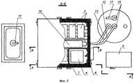
на фиг. 2 - автономный источник питания в плане (разрез по Б-Б);
на фиг. 3 - вид на разрез (по В-В на фиг. 2);
на фиг. 4 - вид на разрез (по Г-Г на фиг. 3).The invention is illustrated by drawings, where
in FIG. 1 shows an autonomous power source (section along AA);
in FIG. 2 - autonomous power source in the plan (section along BB);
in FIG. 3 is a sectional view (along BB in FIG. 2);
in FIG. 4 is a sectional view (along G-D in FIG. 3).
Автономный источник питания содержит силовой агрегат 1, состоящий из двигателя внутреннего сгорания с пусковым устройством и генератора, взаимодействующего через устройство 2 для подзарядки с аккумуляторными батареями 3, и командоаппарат 4, соединенный с аккумуляторными батареями 3 и пусковым устройством двигателя силового агрегата 1, и дополнительно содержит транспортабельную камеру 5 с внешней теплоизоляционной оболочкой 6 с электрическими вводами и выводами и изолированным отсеком 7 для установки командоаппарата 4, с размещенными внутри камеры 5 металлическими опорами 8 для установки аккумуляторных батарей 3 с обеспечением зазоров между ними, терморегулятора 9 в блоке с электрообогревателем и емкости 10 со сменной теплопоглощающей жидкостью 11, используемой также как топливо 11 для двигателя силового агрегата 1, снабженной в свою очередь наливными и сливными отверстиями, соединенными соответственно трубопроводами 12 и 13 с размещенной вне камеры 5 дополнительной емкостью 14 с топливом 11 для двигателя силового агрегата 1, при этом трубопровод 12 наливного отверстия снабжен электронасосом 15, связанным с терморегулятором 9, и снабжен заборным насадком 16, а дополнительная емкость 14 соединена трубопроводом 17 с топливным баком двигателя силового агрегата 1. The self-contained power source comprises a power unit 1, consisting of an internal combustion engine with a starting device and a generator interacting via a
Автономный источник питания (АИП) работает следующим образом. Autonomous power source (AIP) works as follows.
При включении силового агрегата 1, состоящего из двигателя внутреннего сгорания с пусковым устройством и генератора, переменный ток генератора преобразуется в устройстве для подзарядки 2 в постоянный ток, и аккумуляторные батареи 3 по сигналу командоаппарата 4 отключаются от рабочей цепи и подключаются к зарядным цепям; одновременно генератор силового агрегата 1 работает на внешнюю нагрузку. Мощность силового агрегата 1 выбирается в зависимости от условий эксплуатации, типа используемых аккумуляторных батарей и внешней нагрузки по авторской методике и является "НОУ-ХАУ". When you turn on the power unit 1, which consists of an internal combustion engine with a starting device and a generator, the alternator current is converted in the device for recharging 2 to direct current, and the
После окончания заряда всех аккумуляторных батарей 3, по сигналу командоаппарата 4, происходит отключение аккумуляторных батарей 3 от зарядной цепи с подключением к рабочей и происходит выключение двигателя силового агрегата 1. After the end of the charge of all the
Аккумуляторная батарея 3, у которой во время заряда или в процессе разряда на нагрузку какой-либо параметр достигает критического значения, отключается командоаппаратом 4 от электрической цепи, чем исключается возможность отрицательного влияния неисправной аккумуляторной батареи 3 на нормальное функционирование остальных аккумуляторных батарей 3. Во время рабочего цикла топливо 11 в баке двигателя силового агрегата 1 пополняется из дополнительной емкости 14 по трубопроводу 17. Внутренняя температура в транспортабельной камере 5 поддерживается в заданном наиболее благоприятном для применяемого типа аккумуляторных батарей 3 диапазоне терморегулятором 9 в блоке с электрообогревателем и емкости 10 со сменной теплопоглощающей жидкостью 11, используемой также как топливо для двигателя силового агрегата 1. При повышении температуры в транспортабельной камере 5 близко к верхней границе заданного температурного диапазона терморегулятор 9 включает электронасос 15, после чего электронасос 15 начинает подавать в емкость 10 по трубопроводу 12 охлажденную теплопоглощающую жидкость 11 из дополнительной емкости 14, вытесняя из емкости 10 в емкость 14 нагретую теплопоглащающую жидкость 11. После снижения температуры электронасос 15 отключается, и смена теплопоглощающей жидкости 11 прекращается. При снижении температуры воздуха в камере 5 до нижней границы заданного температурного диапазона терморегулятор 9 включает электрообогреватель.
Предлагаемый автономный источник питания (АИП ) позволяет обеспечить устойчивую работу аккумуляторных батарей в наиболее благоприятном для выбранного типа аккумуляторных батарей режиме, что позволяет полностью использовать высокий КПД силового агрегата АИП, сократить расходы на топливо и его транспортировку в труднодоступные и малонаселенные районы. The proposed autonomous power source (AIP) allows for stable operation of the batteries in the most favorable mode for the selected type of battery, which allows you to fully use the high efficiency of the AIP power unit, reduce the cost of fuel and its transportation to remote and sparsely populated areas.
ИСТОЧНИКИ ИНФОРМАЦИИ
1. Иорданишвили Е.К. Термоэлектрические источники питания. - М.: Издательство "Советское радио", 1968, С. 100-102, рис.37.SOURCES OF INFORMATION
1. Iordanishvili E.K. Thermoelectric power supplies. - M .: Publishing house "Soviet Radio", 1968, S. 100-102, Fig. 37.
2. Галкин Ю.М. Электрооборудование автомобилей и тракторов. - М.: Издательство "Машиностроение", 1967, с.8, 9, 40, рис. 2. 2. Galkin Yu.M. Electric equipment of cars and tractors. - M .: Publishing house "Engineering", 1967, p. 8, 9, 40, fig. 2.
Claims (1)
Translated fromRussianPriority Applications (1)
| Application Number | Priority Date | Filing Date | Title |
|---|---|---|---|
| RU2000104030/09ARU2171527C1 (en) | 2000-02-21 | 2000-02-21 | Off-line power supply |
Applications Claiming Priority (1)
| Application Number | Priority Date | Filing Date | Title |
|---|---|---|---|
| RU2000104030/09ARU2171527C1 (en) | 2000-02-21 | 2000-02-21 | Off-line power supply |
Publications (1)
| Publication Number | Publication Date |
|---|---|
| RU2171527C1true RU2171527C1 (en) | 2001-07-27 |
Family
ID=20230793
Family Applications (1)
| Application Number | Title | Priority Date | Filing Date |
|---|---|---|---|
| RU2000104030/09ARU2171527C1 (en) | 2000-02-21 | 2000-02-21 | Off-line power supply |
Country Status (1)
| Country | Link |
|---|---|
| RU (1) | RU2171527C1 (en) |
Cited By (1)
| Publication number | Priority date | Publication date | Assignee | Title |
|---|---|---|---|---|
| RU2528622C1 (en)* | 2010-07-30 | 2014-09-20 | ШЭНЬЧЖЭНЬ БИД АУТО Р энд Д КОМПАНИ ЛИМИТЕД | Accumulator battery heating circuit |
Citations (2)
| Publication number | Priority date | Publication date | Assignee | Title |
|---|---|---|---|---|
| US3805217A (en)* | 1973-01-02 | 1974-04-16 | Gen Electric | Connection bar coupling |
| GB1357933A (en)* | 1971-10-08 | 1974-06-26 | English Electric Co Ltd | Alternating current dynamo electric machines |
- 2000
- 2000-02-21RURU2000104030/09Apatent/RU2171527C1/ennot_activeIP Right Cessation
Patent Citations (2)
| Publication number | Priority date | Publication date | Assignee | Title |
|---|---|---|---|---|
| GB1357933A (en)* | 1971-10-08 | 1974-06-26 | English Electric Co Ltd | Alternating current dynamo electric machines |
| US3805217A (en)* | 1973-01-02 | 1974-04-16 | Gen Electric | Connection bar coupling |
Non-Patent Citations (2)
| Title |
|---|
| ГАЛКИН Ю.M. Электрооборудование автомобилей и тракторов. - М.: Машиностроение, 1967, с.8, 40, рис.3.* |
| ИОРДАНИШВИЛИ E.K. Термоэлектрические источники питания. - М.: Советское радио, 1968, с.100-102, рис.37.* |
Cited By (1)
| Publication number | Priority date | Publication date | Assignee | Title |
|---|---|---|---|---|
| RU2528622C1 (en)* | 2010-07-30 | 2014-09-20 | ШЭНЬЧЖЭНЬ БИД АУТО Р энд Д КОМПАНИ ЛИМИТЕД | Accumulator battery heating circuit |
Similar Documents
| Publication | Publication Date | Title |
|---|---|---|
| CN201332372Y (en) | Residual heat thermoelectric power generation system using circulating liquid cooling | |
| US6605773B2 (en) | Thermoelectric generator for a vehicle | |
| US3110633A (en) | Temperature-sustaining apparatus for automobiles | |
| US8356682B2 (en) | Fuel cell system using external heat sources for maintaining internal temperature | |
| US20190145286A1 (en) | Method for thermoelectric energy generation | |
| WO2012165990A4 (en) | Cooling electric energy generator | |
| KR101494241B1 (en) | Waste heat recovery power generation system | |
| US7812246B2 (en) | Thermoelectric effect device, energy direct conversion system, and energy conversion system | |
| RU2171527C1 (en) | Off-line power supply | |
| US8618406B1 (en) | Thermoelectric power generation method and apparatus | |
| RU174173U1 (en) | MOBILE Cogeneration Power Plant | |
| US20190226441A1 (en) | Generator set startup using renewable energy | |
| Wang et al. | Harvesting waste heat based on thermoelectric generation to drive LED car lamps | |
| Meleta et al. | Truck co-generation system based on combustion heated thermoelectric conversion | |
| RU2782078C1 (en) | Heater with built-in thermoelectric generator | |
| US7340893B1 (en) | Steam generator system | |
| US20200363138A1 (en) | Thermal battery and electricity generation system | |
| Newaz et al. | Vehicle Tracking and Monitoring System for Security Purpose Based on Thermoelectric Generator (TEG). | |
| RU209363U1 (en) | Thermal stabilization device for drives | |
| RU222545U1 (en) | Portable collection device for receiving electrical power | |
| RU2811638C1 (en) | Thermoelectric generator based on seebeck effect | |
| RU128667U1 (en) | HEATING DEVICE | |
| RU2508465C1 (en) | Heater | |
| KR200303224Y1 (en) | A hybrid solar system for generating power and heat | |
| CN107228478A (en) | Water heater and water heater electricity-generating method with electricity generation system |
Legal Events
| Date | Code | Title | Description |
|---|---|---|---|
| MM4A | The patent is invalid due to non-payment of fees | Effective date:20050222 |