RU2162923C2 - Building panel jointing system - Google Patents
Building panel jointing systemDownload PDFInfo
- Publication number
- RU2162923C2 RU2162923C2RU98110272/03ARU98110272ARU2162923C2RU 2162923 C2RU2162923 C2RU 2162923C2RU 98110272/03 ARU98110272/03 ARU 98110272/03ARU 98110272 ARU98110272 ARU 98110272ARU 2162923 C2RU2162923 C2RU 2162923C2
- Authority
- RU
- Russia
- Prior art keywords
- panels
- panel
- edge
- locking
- edges
- Prior art date
Links
Images


Classifications
- E—FIXED CONSTRUCTIONS
- E04—BUILDING
- E04F—FINISHING WORK ON BUILDINGS, e.g. STAIRS, FLOORS
- E04F15/00—Flooring
- E04F15/12—Flooring or floor layers made of masses in situ, e.g. seamless magnesite floors, terrazzo gypsum floors
- E04F15/14—Construction of joints, e.g. dividing strips
- E—FIXED CONSTRUCTIONS
- E04—BUILDING
- E04F—FINISHING WORK ON BUILDINGS, e.g. STAIRS, FLOORS
- E04F15/00—Flooring
- E04F15/02—Flooring or floor layers composed of a number of similar elements
- E—FIXED CONSTRUCTIONS
- E04—BUILDING
- E04F—FINISHING WORK ON BUILDINGS, e.g. STAIRS, FLOORS
- E04F13/00—Coverings or linings, e.g. for walls or ceilings
- E04F13/07—Coverings or linings, e.g. for walls or ceilings composed of covering or lining elements; Sub-structures therefor; Fastening means therefor
- E04F13/08—Coverings or linings, e.g. for walls or ceilings composed of covering or lining elements; Sub-structures therefor; Fastening means therefor composed of a plurality of similar covering or lining elements
- E04F13/0801—Separate fastening elements
- E—FIXED CONSTRUCTIONS
- E04—BUILDING
- E04F—FINISHING WORK ON BUILDINGS, e.g. STAIRS, FLOORS
- E04F15/00—Flooring
- E04F15/02—Flooring or floor layers composed of a number of similar elements
- E04F15/04—Flooring or floor layers composed of a number of similar elements only of wood or with a top layer of wood, e.g. with wooden or metal connecting members
- E—FIXED CONSTRUCTIONS
- E04—BUILDING
- E04F—FINISHING WORK ON BUILDINGS, e.g. STAIRS, FLOORS
- E04F2201/00—Joining sheets or plates or panels
- E04F2201/01—Joining sheets, plates or panels with edges in abutting relationship
- E04F2201/0107—Joining sheets, plates or panels with edges in abutting relationship by moving the sheets, plates or panels substantially in their own plane, perpendicular to the abutting edges
- E04F2201/0115—Joining sheets, plates or panels with edges in abutting relationship by moving the sheets, plates or panels substantially in their own plane, perpendicular to the abutting edges with snap action of the edge connectors
- E—FIXED CONSTRUCTIONS
- E04—BUILDING
- E04F—FINISHING WORK ON BUILDINGS, e.g. STAIRS, FLOORS
- E04F2201/00—Joining sheets or plates or panels
- E04F2201/01—Joining sheets, plates or panels with edges in abutting relationship
- E04F2201/0153—Joining sheets, plates or panels with edges in abutting relationship by rotating the sheets, plates or panels around an axis which is parallel to the abutting edges, possibly combined with a sliding movement
- E—FIXED CONSTRUCTIONS
- E04—BUILDING
- E04F—FINISHING WORK ON BUILDINGS, e.g. STAIRS, FLOORS
- E04F2201/00—Joining sheets or plates or panels
- E04F2201/04—Other details of tongues or grooves
- E04F2201/042—Other details of tongues or grooves with grooves positioned on the rear-side of the panel
- E—FIXED CONSTRUCTIONS
- E04—BUILDING
- E04F—FINISHING WORK ON BUILDINGS, e.g. STAIRS, FLOORS
- E04F2201/00—Joining sheets or plates or panels
- E04F2201/05—Separate connectors or inserts, e.g. pegs, pins, keys or strips
- E04F2201/0517—U- or C-shaped brackets and clamps
- Y—GENERAL TAGGING OF NEW TECHNOLOGICAL DEVELOPMENTS; GENERAL TAGGING OF CROSS-SECTIONAL TECHNOLOGIES SPANNING OVER SEVERAL SECTIONS OF THE IPC; TECHNICAL SUBJECTS COVERED BY FORMER USPC CROSS-REFERENCE ART COLLECTIONS [XRACs] AND DIGESTS
- Y10—TECHNICAL SUBJECTS COVERED BY FORMER USPC
- Y10T—TECHNICAL SUBJECTS COVERED BY FORMER US CLASSIFICATION
- Y10T428/00—Stock material or miscellaneous articles
- Y10T428/16—Two dimensionally sectional layer
- Y10T428/163—Next to unitary web or sheet of equal or greater extent
- Y10T428/164—Continuous two dimensionally sectional layer
- Y10T428/167—Cellulosic sections [e.g., parquet floor, etc.]
Landscapes
- Engineering & Computer Science (AREA)
- Architecture (AREA)
- Civil Engineering (AREA)
- Structural Engineering (AREA)
- Life Sciences & Earth Sciences (AREA)
- Wood Science & Technology (AREA)
- Floor Finish (AREA)
- Joining Of Building Structures In Genera (AREA)
- Finishing Walls (AREA)
- Roof Covering Using Slabs Or Stiff Sheets (AREA)
- Body Structure For Vehicles (AREA)
- Conveying And Assembling Of Building Elements In Situ (AREA)
- Laminated Bodies (AREA)
- Absorbent Articles And Supports Therefor (AREA)
- Load-Bearing And Curtain Walls (AREA)
- Road Signs Or Road Markings (AREA)
- Photovoltaic Devices (AREA)
- Building Environments (AREA)
- Lining Or Joining Of Plastics Or The Like (AREA)
- Spinning Or Twisting Of Yarns (AREA)
- Investigating Or Analysing Biological Materials (AREA)
- Seal Device For Vehicle (AREA)
- Connection Of Plates (AREA)
- Excavating Of Shafts Or Tunnels (AREA)
- Mutual Connection Of Rods And Tubes (AREA)
- Pressure Welding/Diffusion-Bonding (AREA)
- Heat Treatment Of Articles (AREA)
- Road Paving Structures (AREA)
- Forms Removed On Construction Sites Or Auxiliary Members Thereof (AREA)
Abstract
Description
Translated fromRussianИзобретение относится в общем к системе для соединения вдоль смежных соединительных кромок двух строительных панелей, особенно панелей пола. The invention relates generally to a system for joining along adjacent adjacent edges of two building panels, especially floor panels.
Более конкретно, соединение по изобретению таково, что смежные соединяемые кромки образуют первое механическое соединение, скрепляющее кромки стыка друг с другом в первом направлении под прямым углом к основной плоскости панелей, и где запирающее устройство образует второе механическое соединение, скрепляющее панели друг с другом во втором направлении параллельно основной плоскости и под прямым углом к соединяемым кромкам, запирающее устройство содержит запирающий паз, который проходит параллельно и разнесен от кромки соединения одной из панелей, причем он открыт на задней стороне этой панели. More specifically, the joint of the invention is such that adjacent joint edges form a first mechanical joint fastening the edges of the joint to each other in a first direction at right angles to the main plane of the panels, and where the locking device forms a second mechanical joint fastening the panels to each other in the second parallel to the main plane and at right angles to the joined edges, the locking device contains a locking groove that runs parallel and spaced from the connection edge one oh of the panels, and it is open on the back of this panel.
Изобретение предпочтительно используется для соединения напольных панелей, в частности тонких многослойных полов. Однако следует отметить, что изобретение можно также применять для соединения обычных деревянных полов, а также других типов строительных панелей. The invention is preferably used for joining floor panels, in particular thin multilayer floors. However, it should be noted that the invention can also be used to connect conventional wooden floors, as well as other types of building panels.
Соединение упомянутого типа известно, например, из патента Швеции N 450141. Первое механическое соединение достигается посредством соединительных кромок, имеющих шпунты и пазы. Запирающее устройство для второго механического соединения содержит два наклонных запирающих паза, причем на задней стороне каждой панели расположено по одному пазу, и множество разнесенных пружинных зажимов, которые распределены вдоль стыка, при этом их ножки зажаты в пазах, и которые смещаются так, чтобы прочно зажимать панели настила вместе. Такой способ соединения особенно подходит для соединения толстых панелей пола для образования поверхностей значительной протяженности. A joint of the type mentioned is known, for example, from Swedish patent N 450141. The first mechanical joint is achieved by connecting edges having tongues and grooves. The locking device for the second mechanical connection contains two inclined locking grooves, with one groove on the back side of each panel and a plurality of spaced spring clips that are distributed along the joint, while their legs are clamped in the grooves and which are displaced so as to firmly clamp flooring panels together. This joining method is particularly suitable for joining thick floor panels to form surfaces of considerable length.
Тонкие напольные панели толщиной примерно 7-10 мм, особенно для многослойных полов, составили за короткий отрезок времени значительную долю рынка сбыта. Все применяемые тонкие панели для полов укладывают в виде "плавающих" настилов без их закрепления на опорной конструкции. Thin floor panels with a thickness of approximately 7–10 mm, especially for multi-layer floors, constituted a significant market share in a short period of time. All used thin panels for floors are laid in the form of "floating" flooring without fixing them to the supporting structure.
Как правило, напольные панели имеют размер 200 х 1200 мм, причем длинные и короткие стороны выполняют со шпунтами и пазами. Традиционно пол настилают, нанося клей в паз и сжимая панели вместе. Затем шпунт приклеивают в пазу другой панели. As a rule, floor panels have a size of 200 x 1200 mm, with long and short sides performed with tongues and grooves. Traditionally, the floor is laid by applying glue into the groove and squeezing the panels together. Then the tongue is glued into the groove of another panel.
Как правило, многослойный пол состоит из верхнего декоративного изнашивающегося слоя пластика, имеющего толщину примерно 1 мм, промежуточного заполнителя из древесностружечной плиты или другой плиты и слоя основания для уравновешивания конструкции. As a rule, a multilayer floor consists of an upper decorative wearing plastic layer having a thickness of about 1 mm, an intermediate aggregate of a particleboard or other plate and a base layer to balance the structure.
Заполнитель имеет по существу худшие свойства, чем слоистый пластик, например, в отношении его твердости и водонепроницаемости, но тем не менее он необходим главным образом для образования шпунта и паза для сборки. Это значит, что общая толщина должна равняться по крайней мере примерно 7 мм. Однако эти известные многослойные полы, в которых применяют склеенное шпунтовое соединение, имеют несколько недостатков. Aggregate has substantially worse properties than laminate, for example with respect to its hardness and water resistance, but nevertheless it is necessary mainly for the formation of a tongue and groove for assembly. This means that the total thickness should be at least about 7 mm. However, these known multilayer floors using glued tongue and groove joints have several disadvantages.
Во-первых, существует требование, чтобы общая толщина равнялась по крайней мере примерно 7 мм, что влечет за собой нежелательное ограничение в связи с укладкой настила, поскольку легче справиться с низкими порогами, если применяют тонкие напольные панели, и дверь необходимо часто регулировать по высоте, чтобы она свободно открывалась. Кроме того, общезаводские накладные расходы непосредственно связаны с расходом материала. Firstly, there is a requirement that the total thickness is at least about 7 mm, which entails an undesirable restriction in connection with the laying of the flooring, since it is easier to cope with low thresholds if thin floor panels are used, and the door often needs to be adjusted in height so that it opens freely. In addition, factory-wide overheads are directly related to material consumption.
Во-вторых, заполнитель должен быть изготовлен из влагопоглощающего материала, чтобы можно было применять клеи на основе воды во время настила полов. Таким образом невозможно изготовить более тонкие полы с использованием так называемого компактного слоистого пластика из-за отсутствия соответствующих способов склеивания таких невлагопоглощающих материалов заполнителя. Secondly, the aggregate must be made of moisture-absorbing material so that water-based adhesives can be used during flooring. Thus, it is not possible to manufacture thinner floors using the so-called compact laminate due to the lack of appropriate methods for bonding such non-moisture-absorbing aggregate materials.
В-третьих, поскольку слой пластика в многослойных полах является высокоизносостойким, то износ инструмента представляет основную проблему при обработке поверхности при образовании шпунта. Thirdly, since the plastic layer in multilayer floors is highly wear-resistant, wear of the tool is a major problem in surface treatment during sheet pile formation.
В-четвертых, прочность стыка на основе склеенного шпунтового соединения ограничена свойствами заполнителя и клея, а также глубиной и высотой паза. Количество настила зависит главным образом от склеивания. В случае плохого склеивания стык будет открываться в результате растягивающих напряжений, которые возникают, например, в связи с изменением влажности воздуха. Fourth, the strength of the joint based on glued tongue and groove joints is limited by the properties of the filler and adhesive, as well as the depth and height of the groove. The amount of flooring depends mainly on bonding. In case of poor bonding, the joint will open as a result of tensile stresses that occur, for example, due to changes in air humidity.
В-пятых, настил полос со склеиваемыми шпунтовыми соединениями представляет собой трудоемкую операцию, поскольку клей необходимо наносить на каждую панель как на длинных, так и на коротких ее сторонах. Fifth, flooring strips with glued tongue-and-groove joints is a time-consuming operation, since glue must be applied to each panel on both its long and short sides.
В-шестых, уложенный и склеенный пол невозможно разобрать без разрушения соединений. Таким образом, снятые напольные панели нельзя снова использовать. Это является недостатком, особенно в домах, сдаваемых в аренду, где конкретную квартиру необходимо возвратить к ее первоначальному доарендному состоянию. Sixth, a laid and glued floor cannot be dismantled without breaking the joints. Therefore, removed floor panels cannot be reused. This is a drawback, especially in rental houses where a particular apartment needs to be returned to its original pre-rental state.
Поврежденные или изношенные панели невозможно заменить без приложения чрезмерных усилий, однако такие замены особенно желательны в коммунальных домах и в других помещениях, где части настила пола подвергаются значительному износу. Damaged or worn panels cannot be replaced without excessive force, but such replacement is especially desirable in communal homes and other areas where parts of the flooring are subject to significant wear.
В-седьмых, известные многослойные настилы пола оказываются непригодными, когда их применение связано со значительным риском проникновения влаги в заполнитель, чувствительный к влаге. Seventh, the known multi-layer flooring is unsuitable when their use is associated with a significant risk of moisture penetrating into the moisture sensitive aggregate.
В-восьмых, современные твердые "плавающие" или незакрепленные настилы пола требуют, до настила панелей на твердый черный пол, укладки отдельного подстилающего слоя из плит, войлока, пенопласта или т.п., который должен заглушать звуки от ударов и делать пол более приятным для ходьбы. Укладка подстилающего слоя представляет собой сложную операцию, поскольку подстилающий слой необходимо размещать кромку к кромке. Различные подстилающие слои влияют на свойства пола. Eighth, modern solid “floating” or non-fixed flooring requires, prior to the flooring of the panels on a hard black floor, laying a separate underlying layer of plates, felt, polystyrene or the like, which should drown out the sounds from impacts and make the floor more pleasant for walking. Laying the underlayer is a difficult operation, since the underlayer must be placed edge to edge. Various underlying layers affect the properties of the floor.
Таким образом, для устранения упомянутых недостатков известных технических решений необходим войлок. Однако применять известные способы соединения посредством склеиваемых шпунтов и пазов для очень тонких полов, например, толщиной примерно 3 мм невозможно, поскольку соединение на основе шпунтового соединения не будет достаточно прочным, причем его практически невозможно образовать для таких тонких настилов. Thus, to eliminate the aforementioned disadvantages of the known technical solutions, felt is needed. However, it is not possible to apply the known joining methods by means of glued tongues and grooves for very thin floors, for example with a thickness of about 3 mm, since the joining based on the tongue and groove joint will not be strong enough, and it is practically impossible to form for such thin decks.
Для таких тонких полов неприемлемы и любые другие известные способы соединения. Другой причиной возникновения проблем при изготовлении тонких настилов, например, из компактных слоистых пластиков является то, что допуски на толщину панелей составляют примерно 0,2-0,3 мм для панели толщиной примерно 3 мм. 3-мм панель из компактного слоистого пластика, имеющая такой допуск на толщину, будет иметь, если ее пришлифовать до равномерной толщины на ее задней стороне, асимметричное расположение, что повлечет за собой риск возникновения вздутий. Кроме того, если панели имеют различную толщину, то это также будет означать, что соединение будет подвергаться чрезмерной нагрузке. For such thin floors, any other known joining methods are not acceptable. Another cause of problems in the manufacture of thin decks, for example, from compact laminate, is that the thickness tolerances of the panels are about 0.2-0.3 mm for a panel with a thickness of about 3 mm. A 3 mm panel made of compact laminate having such a thickness tolerance will have, if sanded to a uniform thickness on its rear side, an asymmetric arrangement, which will entail the risk of bloating. In addition, if the panels have different thicknesses, this will also mean that the connection will be subjected to excessive load.
Упомянутые проблемы невозможно также устранить и при использовании двойной клейкой ленты или т.п. на нижней стороне панелей, поскольку такое соединение будет сразу же сцепляться и оно не позволит проводить последующее регулирование, как и в случае с обычным способом склеивания. The mentioned problems cannot be eliminated also when using double adhesive tape or the like. on the underside of the panels, since such a connection will immediately adhere and it will not allow subsequent adjustment, as is the case with the conventional gluing method.
Применение U-образных зажимов типа, описанного в упомянутом патенте Швеции N 450141, или подобных способов для устранения указанных недостатков не является приемлемым решением. Смещаемые зажимы этого типа особенно нельзя применять для соединения панелей такой небольшой толщины, как, например, 3 мм. Обычно панели пола невозможно разобрать без доступа к их нижним сторонам. The use of U-shaped clamps of the type described in the aforementioned Swedish patent N 450141, or similar methods to eliminate these disadvantages is not an acceptable solution. Movable clamps of this type are not particularly suitable for joining panels of such a small thickness, such as, for example, 3 mm. Typically, floor panels cannot be disassembled without access to their undersides.
Эта известная технология, основанная на применении зажимов, имеет дополнительные недостатки:
последующее регулирование панелей в их продольном направлении представляет собой сложную операцию в связи с их настилом, поскольку зажимы заставляют панели плотно прижиматься друг к другу;
- настил полос с использованием зажимов требует затраты времени;
- этот способ можно применять только в тех случаях, если напольные панели лежат на расположенных снизу вспомогательных балках с зажимами, расположенными между ними. Для настила тонких полов на сплошную плоскую опорную конструкцию такие зажимы нельзя применять;
- напольные панели можно соединить вместе только на их длинных сторонах. На коротких сторонах не предусмотрено соединение зажимом.This known technology, based on the use of clamps, has additional disadvantages:
the subsequent adjustment of the panels in their longitudinal direction is a complex operation in connection with their flooring, since the clamps cause the panels to be pressed tightly against each other;
- flooring strips using clamps requires time;
- this method can be used only in cases where floor panels lie on the auxiliary beams located below from below with clamps located between them. For flooring of thin floors on a continuous flat supporting structure, such clamps cannot be used;
- floor panels can only be joined together on their long sides. On the short sides there is no clamp connection.
Таким образом, задачей изобретения является устранение указанных недостатков и создание системы для соединения вместе строительных панелей, особенно панелей для твердых незакрепленных ("плавающих") полов, которая позволяет применять напольные панели уменьшенной толщины, чем современные напольные панели. Thus, the object of the invention is to eliminate these drawbacks and create a system for joining together building panels, especially panels for solid loose ("floating") floors, which allows the use of floor panels of reduced thickness than modern floor panels.
Конкретной задачей изобретения является создание системы для соединения панелей, которая позволяет просто, дешево и рациональным способом:
- образовать соединение между напольными панелями без необходимости применения клея, причем особенно соединения, основанного главным образом только на механических соединениях между панелями;
- соединять напольные панели, которые имеют меньшую толщину, чем современные многослойные полы, и имеют, за счет использования различного материала заполнителя, превосходные свойства, чем современные полы толщиной даже 3 мм;
- позволяет образовать такое соединение между тонкими панелями пола, которое исключит какую-либо неравномерность в стыке из-за допусков на толщину панелей;
- позволяет соединять все кромки панелей;
- уменьшает износ инструмента при изготовлении напольных панелей с твердыми поверхностными слоями;
- допускает повторную разборку и сборку ранее настиланных полос без повреждения панелей, при этом обеспечивая высокое качество настила полов;
- позволяет получить влагостойкие полы;
- исключать необходимость в точном отдельном размещении подстилающего слоя или основы до настила напольных панелей; и
- значительно сокращает время для соединения панелей.A specific objective of the invention is the creation of a system for connecting panels, which allows a simple, cheap and rational way:
- to form a connection between the floor panels without the need for glue, and especially a connection based mainly only on mechanical joints between the panels;
- to connect floor panels that are thinner than modern multilayer floors and, due to the use of various aggregate materials, have superior properties than modern floors even with a thickness of even 3 mm;
- allows you to create a connection between thin floor panels that eliminates any unevenness in the joint due to tolerances on the thickness of the panels;
- allows you to connect all the edges of the panels;
- reduces tool wear in the manufacture of floor panels with solid surface layers;
- allows re-disassembly and assembly of previously laid strips without damaging the panels, while ensuring high quality flooring;
- allows you to get moisture resistant floors;
- eliminate the need for precise separate placement of the underlying layer or base to the flooring of the floor panels; and
- significantly reduces the time for connecting panels.
Эти и другие цели изобретения достигаются с системой для соединения панелей, имеющей признаки, раскрытые в приложенной формуле изобретения. These and other objectives of the invention are achieved with a system for connecting panels having the features disclosed in the attached claims.
Итак, изобретение относится к системе для образования соединения вдоль смежных соединительных кромок двух строительных панелей, особенно напольных панелей, согласно которой:
смежные кромки соединения образуют вместе первое механическое соединение, скрепляющее соединяемые кромки друг с другом в первом направлении под прямым углом к главной плоскости панелей, при этом
запирающее устройство, расположенное на задней стороне панелей, образует второе механическое соединение, скрепляющее панели друг с другом во втором направлении параллельно главной плоскости и под прямым углом к стыку, причем запирающее устройство содержит запирающий паз, который проходит параллельно с разнесением от соединяемой кромки одной из панелей, названной панелью с пазом, и которая открыта на задней стороне панели с пазом, причем система отличается тем, что:
запирающее устройство дополнительно содержит планку, выполненную за одно целое с другой панелью, названной панелью с планкой, причем планка проходит по существу по всей длине соединительной кромки панели с планкой и снабжена запирающим элементом, выступающим от планки таким образом, что, когда панели соединяют вместе, планка выступает на задней стороне панели, имеющей паз, с ее запирающим элементом, принимаемым запирающим пазом на панели с пазом;
панели, когда их соединяют вместе, могут занимать относительное положение во втором направлении, в котором существует зазор между запирающим пазом и фиксирующей поверхностью на запирающем элементе, который обращен в сторону кромок соединения и является действенным во втором механическом соединении;
первое и второе механические соединения позволяют панелям взаимно смещаться в направлении кромок соединения, и что второе механическое соединение выполнено так, что оно позволяет запирающему элементу оставлять запирающий паз, если панели с пазом поворачивают вокруг ее кромки соединения под углом в сторону от планки.Thus, the invention relates to a system for forming a joint along adjacent connecting edges of two building panels, especially floor panels, according to which:
adjacent edges of the joint form together the first mechanical joint fastening the joint edges to each other in the first direction at right angles to the main plane of the panels, while
a locking device located on the rear side of the panels forms a second mechanical connection fastening the panels to each other in the second direction parallel to the main plane and at right angles to the joint, the locking device comprising a locking groove that extends parallel to the spacing from the joined edge of one of the panels , called a panel with a groove, and which is open on the rear side of the panel with a groove, the system being characterized in that:
the locking device further comprises a strip made integrally with another panel, called a panel with a strip, the strip extending substantially along the entire length of the connecting edge of the panel with the strip and provided with a locking element protruding from the strip so that when the panels are connected together, the bar protrudes on the rear side of the panel having a groove, with its locking element adopted by the locking groove on the panel with the groove;
the panels, when they are joined together, can occupy a relative position in the second direction, in which there is a gap between the locking groove and the fixing surface on the locking element, which faces the connection edges and is effective in the second mechanical connection;
the first and second mechanical connections allow the panels to be mutually displaced in the direction of the edges of the connection, and that the second mechanical connection is made so that it allows the locking element to leave a locking groove if the panels with the groove are rotated around its connection edge at an angle to the side of the bar.
Термин "задняя сторона", как его применяют здесь, включает в себя любую сторону панели, расположенную позади или под передней стороной панели. Таким образом, плоскость открытия запирающего паза в панели, имеющей паз, можно разместить на расстоянии от задней поверхности панели, лежащей на опорной конструкции. The term "back side", as used here, includes any side of the panel located behind or under the front side of the panel. Thus, the opening plane of the locking groove in the panel having the groove can be placed at a distance from the rear surface of the panel lying on the supporting structure.
Кроме того, планку, которая проходит в соответствии с изобретением по существу по всей длине соединительной кромки панели с планкой, следует рассматривать как охватывающую оба случая, то есть когда планка представляет собой сплошной, непрерывный элемент и когда планка состоит в ее продольном направлении из нескольких частей, закрывающих вместе основную часть соединительной кромки. In addition, the strip, which extends in accordance with the invention along substantially the entire length of the connecting edge of the panel with the strip, should be considered as covering both cases, that is, when the strip is a solid, continuous element and when the strip consists of several parts in its longitudinal direction covering together the main part of the connecting edge.
Следует также отметить, что (i) именно первое и второе механические соединения сами по себе допускают взаимное смещение панелей в направлении кромок соединения и что (ii) второе механическое соединение как таковое позволяет запирающему элементу оставлять запирающий паз, если панель с пазом поворачивают вокруг ее кромки соединения под углом в сторону от планки. It should also be noted that (i) it is the first and second mechanical joints that themselves allow mutual displacement of the panels towards the edges of the joint, and that (ii) the second mechanical joint as such allows the locking element to leave a locking groove if the panel with the groove is rotated around its edge connections at an angle to the side of the bar.
В объеме изобретения могут быть также предусмотрены средства, например, клей, и механические устройства для противодействия или исключения такого смещения и/или размещения под углом вверх. Means, for example, glue, and mechanical devices can also be provided within the scope of the invention to counteract or eliminate such displacement and / or placement at an upward angle.
Система в соответствии с изобретением позволяет достичь потайного точного запирания как коротких, так и длинных сторон в твердых тонких полах. Напольные панели можно быстро и удобно разобрать в обратном порядке настила полов без какого-либо риска повреждения панелей, при этом одновременно обеспечивается высокое качество настила полов. Панели можно собрать и разобрать значительно быстрее, чем с известными системами, причем любые поврежденные или изношенные панели можно заменить, удалив и снова настелив части пола. The system according to the invention makes it possible to achieve an accurate secret locking of both short and long sides in hard thin floors. Floor panels can be quickly and conveniently disassembled in the reverse order of flooring without any risk of damage to the panels, while at the same time high quality flooring is ensured. Panels can be assembled and disassembled much faster than with known systems, and any damaged or worn panels can be replaced by removing and re-laying parts of the floor.
В соответствии с особенно предпочтительным исполнением изобретения предложена система, позволяющая точно соединять тонкие напольные панели, имеющие, например, толщину порядка 3 мм, и при этом образовать гладкую верхнюю поверхность, независимо от допусков, в точке соединения. In accordance with a particularly preferred embodiment of the invention, there is provided a system for precisely connecting thin floor panels having, for example, a thickness of the order of 3 mm, and at the same time forming a smooth upper surface, regardless of tolerances, at the connection point.
Для этой цели планку помещают в уравновешивающий паз, который утоплен на задней стороне панели с планкой и имеет точное заданное расстояние от его нижней части до передней стороны панели с планкой. Часть планки, выступающая за панель с пазом, входит в соответствующий уравновешивающий паз, который утоплен на задней стороне панели с пазом и имеет такое же точное и заданное расстояние от его нижней части до передней стороны панели с пазом. For this purpose, the bar is placed in a balancing groove, which is recessed on the rear side of the panel with the bar and has an exact predetermined distance from its lower part to the front side of the panel with the bar. The part of the strip that extends beyond the panel with the groove enters the corresponding balancing groove, which is recessed on the rear side of the panel with the groove and has the same exact and predetermined distance from its lower part to the front side of the panel with the groove.
В таком случае толщина планки будет по крайней мере такой большой, чтобы задняя сторона планки находилась заподлицо и предпочтительно выступала слегка под задней стороной панелей. В этом варианте исполнения панели будут всегда лежать в точке соединения с их уравновешивающими пазами на планке. In this case, the thickness of the strip will be at least so large that the back side of the strip is flush and preferably protrudes slightly below the rear side of the panels. In this embodiment, the panels will always lie at the junction point with their balancing grooves on the bar.
Это позволяет выравнивать допуски и сообщить необходимую прочность соединению. Планка передает усилия, направленные горизонтально и вверх, панелям, и усилия, направленные вниз, существующему черному полу. This allows you to align tolerances and communicate the required strength to the joint. The plank transfers forces directed horizontally and up to the panels, and forces directed down to the existing subfloor.
Предпочтительно планка может состоять из материала, который является гибким, упругим и прочным и его можно распилить. Предпочтительным материалом для планки является листовой алюминий. В алюминиевой планке достаточная прочность может достигаться при толщине планки порядка 0,5 мм. Preferably, the plank may consist of a material that is flexible, resilient and durable and can be sawn. The preferred material for the strap is aluminum sheet. In the aluminum strip, sufficient strength can be achieved with a strip thickness of the order of 0.5 mm.
Для того чтобы можно было снять ранее настиланные и соединенные напольные панели простым способом, конкретное исполнение изобретения отличается тем, что, когда панель с пазом прижимают к панели с планкой во втором направлении и поворачивают под углом в сторону от планки, то максимальное расстояние между осью вращения панели с пазом и фиксирующей поверхностью запирающего паза ближе всего от кромок соединения является таким, что запирающий элемент может оставлять запирающий паз без контакта с фиксирующей поверхностью запирающего паза. Такой демонтаж может достигаться, даже если упомянутый зазор между запирающим пазом и фиксирующей поверхностью не будет превышать 0,2 мм. In order to be able to remove previously laid and connected floor panels in a simple way, a specific embodiment of the invention is characterized in that when the panel with a groove is pressed against the panel with the strip in the second direction and rotated at an angle to the side of the strip, the maximum distance between the axis of rotation the panel with the groove and the locking surface of the locking groove closest to the edges of the connection is such that the locking element can leave the locking groove without contact with the locking surface of the locking groove. Such dismantling can be achieved even if the aforementioned gap between the locking groove and the fixing surface does not exceed 0.2 mm.
В соответствии с изобретением фиксирующая поверхность запирающего элемента способна обеспечить достаточно прочное крепление даже при очень небольшой высоте фиксирующей поверхности. Эффективное соединение панелей пола толщиной 3 мм может достигаться с фиксирующей поверхностью, имеющей такую малую высоту как, например, 2 мм. In accordance with the invention, the locking surface of the locking element is capable of providing a sufficiently strong fastening even at a very small height of the locking surface. An effective connection of 3 mm thick floor panels can be achieved with a fixing surface having a height as small as, for example, 2 mm.
Фиксирующая поверхность высотой даже 0,5 мм может обеспечить достаточное крепление. Термин "фиксирующая поверхность", как он применяется здесь, относится к части запирающего элемента, входящего в запирающий паз для образования второго механического соединения. A locking surface with a height of even 0.5 mm can provide sufficient fastening. The term "locking surface", as used here, refers to the part of the locking element included in the locking groove for the formation of the second mechanical connection.
Для оптимального исполнения изобретения планка и запирающий элемент должны быть выполнены с высокой точностью на панели с планкой. В частности, фиксирующая поверхность запирающего элемента должна быть расположена на соответствующем расстоянии от соединяемой кромки панели с планкой. For optimal performance of the invention, the bar and the locking element must be made with high accuracy on the panel with the bar. In particular, the locking surface of the locking element should be located at an appropriate distance from the joined edge of the panel with the bar.
Кроме того, длина контакта в напольных панелях должна быть минимальной, поскольку она уменьшает прочность пола. In addition, the contact length in floor panels should be kept to a minimum, as it reduces floor strength.
Планку можно изготовить со стопорным штифтом известными способами, например посредством экструдирования алюминия или пластмассы в соответствующий профиль, который затем приклеивают к напольной панели или вставляют в специальные пазы. The bar can be made with a locking pin by known methods, for example by extruding aluminum or plastic into a suitable profile, which is then glued to the floor panel or inserted into special grooves.
Однако эти и другие традиционные способы не обеспечивают оптимальной работы и оптимального уровня экономии. Для получения системы для соединения панелей в соответствии с изобретением изготавливают планку соответственно из листового алюминия и прикрепляют ее механически к панели с планкой. However, these and other traditional methods do not provide optimal performance and an optimal level of savings. To obtain a system for connecting panels in accordance with the invention, a strip is made of aluminum sheet, respectively, and mechanically attached to a panel with a strip.
Настил панелей можно осуществлять, поместив сначала панель с планкой на черный пол и затем переместив панель с пазом с ее длинной стороной, направленной вверх, до длинной стороны панели с планкой под углом между главной плоскостью панели с пазом и черным полом. Когда соединяемые кромки устанавливают в контакте друг с другом для образования первого механического соединения, панель с пазом размещают под углом вниз так, чтобы запирающий элемент входил в запирающий паз. The flooring of the panels can be done by first placing the panel with the bar on the black floor and then moving the panel with the groove with its long side facing up to the long side of the panel with the bar at an angle between the main plane of the panel with the groove and the black floor. When the joined edges are brought into contact with each other to form the first mechanical connection, the panel with the groove is placed at an angle downward so that the locking element fits into the locking groove.
Настил полов можно также осуществлять, поместив сначала панель с планкой и панель с пазом в плоском положении на черный пол и затем соединив панели параллельно их основным плоскостям, при этом сгибая планку вниз до тех пор, пока запирающий элемент не защелкнется в запирающем пазу. Flooring can also be done by first placing the panel with the bar and the panel with the groove in a flat position on the black floor and then connecting the panels parallel to their main planes, while bending the bar down until the locking element clicks into place in the locking groove.
Этот способ настила полос обеспечивает, в частности, механическое соединение как коротких, так и длинных сторон панелей пола. Например, длинные стороны можно соединить вместе, применяя первый способ настила панели, имеющей паз, направленный вниз под углом, тогда как короткие стороны соединяют вместе путем перемещения панели с пазом в ее продольном направлении до тех пор, пока ее короткая сторона не прижмется и замкнется на короткой стороне смежной панели того же ряда. This method of flooring strips provides, in particular, the mechanical connection of both the short and long sides of the floor panels. For example, the long sides can be joined together using the first method of flooring a panel having a groove pointing downward at an angle, while the short sides are joined together by moving the panel with the groove in its longitudinal direction until its short side is pressed and closed on the short side of an adjacent panel of the same row.
В связи с их изготовлением панели пола можно снабдить основным слоем или подложкой, например, из половой доски, пенопласта или войлока. Слой основы должен предпочтительно закрывать планку таким образом, чтобы стык между нижними слоями был смещен относительно стыка между панелями пола. In connection with their manufacture, the floor panels can be provided with a base layer or substrate, for example of a floorboard, polystyrene or felt. The base layer should preferably close the bar so that the joint between the lower layers is offset from the joint between the floor panels.
Упомянутые и другие признаки и преимущества изобретения станут более понятными из приложенной формулы изобретения и следующего описания вариантов исполнения изобретения. Mentioned and other features and advantages of the invention will become more apparent from the attached claims and the following description of embodiments of the invention.
Далее изобретение будет описано более подробно со ссылкой на приложенные фигуры чертежей. The invention will now be described in more detail with reference to the attached drawings.
Фиг. 1 и 2 показывают схематически, в два этапа, соединение вместе двух панелей пола различной толщины в "плавающем" или незакрепленном положении в соответствии с первым вариантом исполнения изобретения. FIG. 1 and 2 show schematically, in two stages, joining together two floor panels of different thicknesses in a "floating" or loose position in accordance with the first embodiment of the invention.
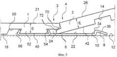
Фиг. 3, 4, 5 показывают, в три этапа, способ механического соединения двух напольных панелей в соответствии со вторым вариантом исполнения изобретения. FIG. 3, 4, 5 show, in three stages, a method for mechanically joining two floor panels in accordance with a second embodiment of the invention.
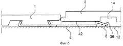
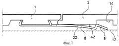
Фиг. 6-8, показывают, в три этапа, другой способ механического соединения напольных панелей, представленных на фиг. 3-5. FIG. 6-8, show in three stages, another method for mechanically joining the floor panels of FIG. 3-5.
Фиг. 9 и 10 показывают напольную панель согласно фиг. 3-5, как это видно снизу и сверху соответственно. FIG. 9 and 10 show the floor panel of FIG. 3-5, as seen from below and above, respectively.
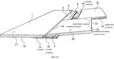
Фиг. 11 показывает в перспективе способ настила и соединения панелей пола в соответствии с третьим вариантом исполнения изобретения. FIG. 11 shows in perspective a method of flooring and joining floor panels in accordance with a third embodiment of the invention.
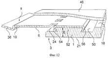
Фиг. 12 показывает в перспективе и снизу первого варианта установки планки на панель пола. FIG. 12 shows, in perspective and from below, a first embodiment of mounting a plank on a floor panel.
Фиг. 13 показывает в разрезе второй вариант установки планки на панель пола. FIG. 13 shows a sectional view of a second embodiment of mounting a bar on a floor panel.
Фиг. 1 и 2 показывают первую панель 1 пола, которая дальше будет называться панелью с планкой, и вторую панель 2 пола, называемую дальше панелью с пазом. FIG. 1 and 2 show the
Термины "панель с планкой" и "панель с пазом" предназначены просто для упрощения описания изобретения, тогда как на практике панели 1 и 2 обычно одинаковые. Панели 1 и 2 могут быть изготовлены из компактных слоистых пластиков и иметь толщину примерно 3 мм с допуском на толщину примерно ±0,2 мм. С учетом этого допуска на толщину панели 1,2 показаны, как имеющие различную толщину (фиг. 2), причем панель 1 с планкой имеет максимальную толщину (3.2 мм), а панель 2 с пазом имеет минимальную толщину (2.8 мм). The terms “panel with a bar” and “panel with a groove” are intended simply to simplify the description of the invention, while in
Для того чтобы можно было механически соединять панели 1, 2 на противоположно расположенных соединяемых кромках, обычно обозначенных в позициях 3 и 4, панели 1 снабжены пазами и планками, как будет описано ниже. In order to be able to mechanically connect the
Фиг. 1 и 2 и фиг. 9 и 10 показывают основную конструкцию напольных панелей снизу и сверху соответственно. FIG. 1 and 2 and FIG. 9 and 10 show the basic construction of floor panels from below and from above, respectively.
От кромки 3 соединения панели 1 с планкой, то есть одной длинной стороны, выступает планка 6, установленная на заводе на нижней стороне панели 1 с планкой и проходящая по всей кромке 3 соединения. From the
Планку 6, которая изготовлена из гибкого и упругого листового алюминия, можно прикрепить механически при помощи клея или любым другим соответствующим способом. На фиг. 1 и 2 показано, что планка 6 приклеена, тогда как на фиг. 9 и 10 она установлена при помощи механического соединения, которое будет описано более подробно. The
Можно применять другие материалы для планки, например листы из других материалов, а также алюминиевые и пластмассовые профили. Либо планку 6 можно выполнить за одно целое с панелью 1 с планкой. В любом случае планка 6 должна быть выполнена как одно целое с панелью 1, имеющей планку, то есть она не должна устанавливаться на панели 1 с планкой во время настила пола. В качестве неограничивающего примера планка 6 может иметь ширину примерно 30 мм и толщину примерно 0.5 мм. Other plank materials can be used, for example sheets of other materials, as well as aluminum and plastic profiles. Or, the
Как это видно на фиг. 9 и 10, подобная, хотя и более короткая планка 6', образована также на одной короткой стороне 3' панели 1 с планкой. Однако более короткая планка 6' не проходит по всей короткой стороне 3', но обычно она идентична планке 6 и, следовательно, подробно здесь не описывается. As can be seen in FIG. 9 and 10, a similar, albeit
Кромка планки 6, обращенная в сторону от кромки 3 соединения, выполнена с запирающим элементом 8, проходящим по всей планке 6. Запирающий элемент 8 имеет фиксирующую поверхность 10, обращенную в сторону кромки 3 соединения и имеющую высоту, например, 0.5 мм. Запирающий элемент 8 выполнен таким образом, что, когда пол настилают и панель 2 с планкой, показанную на фиг. 1, прижимают ее кромкой 4 стыка (соединительной кромкой 4) к кромке 3 стыка (соединительной кромке 3) панели 1 с планкой и размещают под углом на черный пол 12, как показано на фиг. 2, то он входит в запирающий паз 14, образованный на нижней стороне 16 панели 2 с пазом 2, проходящий параллельно и разнесенный от кромки 4 стыка. The edge of the
Как показано на фиг. 1, запирающий элемент 8 и запирающий паз 14 образуют вместе механическое соединение, закрепляющее панели 1, 2 друг с другом в направлении Д2. Более конкретно, фиксирующая поверхность 10 запирающего элемента 8 служит в качестве упора по отношению к поверхности запирающего паза 14 наиболее близко от кромки 4 стыка. As shown in FIG. 1, the locking
Когда панели 1 и 2 соединяют вместе, они могут занимать, однако, такое относительное положение в направлении Д2, где имеется небольшой зазор Δ между фиксирующей поверхностью 10 и запирающим пазом 14. Это механическое соединение в направлении Д2 позволяет панелям 1, 2 взаимно смещаться в направлении стыка (соединения), что значительно упрощает настилку полов и позволяет соединять вместе короткие стороны благодаря закреплению за счет защелкивающего действия. When
Как видно на фиг. 9 и 10, каждая панель в системе имеет планку 6 на одной длинной стороне 3 и запирающий паз 14 на другой длинной стороне 4, а также планку 6 на одной короткой стороне 3 и запирающий паз 14 на другой короткой стороне 4. As seen in FIG. 9 and 10, each panel in the system has a
Кроме того, кромка 3 стыка панели 1 с планкой имеет на ее нижней стороне 18 канавку 20, проходящую по всей кромке 3 стыка и образующую вместе с верхней поверхностью 22 планки 6 поперечную открытую выемку 24. Соединительная кромка 4 панели 2 с пазом имеет на своей верхней стороне 26 соответствующее углубление 28, образующее запирающий выступ 30, который должен входить в выемку 24 для образования механического соединения, закрепляющего кромки 3, 4 стыка друг с другом в направлении Д1. In addition, the
Это соединение может достигаться с другими конструкциями кромок 3, 4 стыка, например, посредством их скоса так, чтобы кромка 4 стыка панели 2 с пазом проходила наклонно вниз под кромку 3 стыка панели 1 с планкой для ее закрепления между этой кромкой и планкой 6. This connection can be achieved with other designs of the
Панели 1, 2 можно удалить в обратном порядке их расположения, причем без какого-либо риска повреждения соединения, и снова настелить их.
Планку 6 размещают в выравнивающий допуск паз 40, образованный на нижней стороне 18 панели 1 с планкой смежно с кромкой 3 стыка. В этом варианте исполнения ширина выравнивающего паза 40 примерно равна половине ширины планки 6, то есть она составляет примерно 15 мм. The
Благодаря выравнивающему пазу 40 обеспечивается то, что между верхней стороной 21 панели 1 и нижней частью паза 40 будет всегда точно заданное расстояние Е, которое слегка меньше минимальной толщины (2.8 мм) половых панелей 1, 2. Панель 2 с пазом имеет соответствующую выравнивающую допуск поверхность или паз 42 на нижней стороне 16 кромки 4 стыка. Thanks to the leveling
Расстояние между выравнивающей поверхностью 42 и верхней стороной 26 панели 2 с пазом равно упомянутому точному расстоянию Е. Кроме того, выбирают толщину планки 6, чтобы нижняя сторона 44 планки была расположена слева ниже нижних сторон 18 и 16 половых панелей 1 и 2 соответственно. The distance between the leveling
Таким образом, весь стык будет лежать на планке 6, и все вертикальные, направленные вниз усилия, будут передаваться достаточно черному полу 12 без создания каких-либо напряжений на соединяемые кромки 3, 4. Благодаря наличию выравнивающих пазов 40, 42 будет достигаться полностью равномерное соединение на верхней стороне, несмотря на допуски на толщину панелей 1, 2 без осуществления какой-либо пришлифовки или т.п. операции на всех панелях. Это особенно исключает риск повреждения нижнего слоя компактного слоистого пластика, которое может привести к вспучиванию панелей. Thus, the entire joint will lie on the
Теперь будет рассмотрен вариант исполнения по фиг. 3-5, показывающий последовательно по существу тот же способ настила полов, как и на фиг. 1 и 2. Вариант исполнения, показанный на фиг. 3-5, отличается от варианта исполнения на фиг. 1 и 2 в основном тем, что планку 6 прикрепляют на панели 1 с планкой посредством механического соединения, а не клея. Now, the embodiment of FIG. 3-5, showing successively substantially the same flooring method as in FIG. 1 and 2. The embodiment shown in FIG. 3-5, differs from the embodiment of FIG. 1 and 2 mainly by the fact that the
Для получения этого механического соединения, показанного более подробно на фиг. 12, на нижней стороне 18 панели 1 с планкой образуют паз 50 на расстоянии от выемки 24. Паз 50 можно образовать либо в виде сплошной канавки, проходящей по всей длине панели 1, либо в виде нескольких отдельных канавок. To obtain this mechanical connection, shown in more detail in FIG. 12, a
Паз 50 образует вместе с выемкой 24 захватывающую кромку 52 в форме ласточкина хвоста, нижняя сторона которой имеет точное выравнивающее расстояние Е до верхней стороны 21 панели 1 с планкой. Алюминиевая планка 6 имеет множество отштампованных и выгнутых выступов 54, а также одну или несколько кромок 56, которые изогнуты вокруг противоположных сторон захватывающей кромки 52 в крепежном зацеплении с ними. Это соединение показано подробно снизу в перспективе на фиг. 12. The
Либо механическое соединение между планкой 6 и панелью 1 с планкой можно образовать, как показано на фиг. 13, представляющей вид в разрезе с частичным вырезом панели 1 с планкой, повернутой верхней стороной вниз. Как показано на фиг. 13, механическое соединение содержит углубление 58 в форме ласточкина хвоста на нижней стороне 18 панели 1 с планкой, а также выступы кромки 60, пробитые и выгнутые из планки 6 и прижатые к противоположно расположенным внутренним сторонам углубления 58. Or, a mechanical connection between the
Конструкция, показанная на фиг. 3-5, дополнительно отличается тем, что запирающий элемент 8 планки 6 выполнен в виде элемента, согнутого из листа алюминия и имеющего рабочую фиксирующую поверхность 10, выступающую под прямым углом от передней стороны 22 планки 6 на высоту, например, 0.5 мм, и закругленную направляющую поверхность 34, упрощающую ввод запирающего элемента 8 в запирающий паз 14, когда панель 2 с пазом устанавливают под углом вниз в сторону черного пола 12 (фиг. 4), а также часть 36, которая наклонена в сторону черного пола 12 и которая не участвует в способе настила, показанном на фиг. 3-5. The construction shown in FIG. 3-5, further differs in that the locking
Также на фиг. 3-5 можно увидеть, что кромка 3 стыка панели 1 с планкой имеет небольшой скос 70, который взаимодействует во время настила полов с соответствующим верхним скосом 72 кромки 4 стыка панели 2 с пазом таким образом, что панели 1 и 2 вынуждены перемещаться вертикально в сторону друг к другу, когда их соединяемые кромки 3, 4 перемещают друг к другу, а панели сжимают вместе горизонтально. Also in FIG. 3-5, you can see that the
Предпочтительно фиксирующую поверхность 10 располагают таким образом относительно кромки 3 стыка, что когда панель 2 с пазом, начиная от позиции соединения, показанной на фиг. 5, прижимают горизонтально в направлении Д2 к панели 1 с планкой и поворачивают под углом от планки 6, максимальное расстояние между осью вращения А панели 2 с пазом и фиксирующей поверхностью 10 запирающего паза является таким, что запирающий элемент 8 может оставлять запирающий паз 14 без контакта с ним. Preferably, the fixing
Фиг. 6-7 показывают другой способ соединения для механического соединения вместе панелей пола, представленных на фиг. 3-8. Способ, показанный на фиг. 3-8, основан на том факте, что планка 6 является упругой и особенно подходит для соединения вместе коротких сторон панелей пола, которые уже соединены вдоль одной длинной стороны, как это видно на фиг. 3-5. FIG. 6-7 show another joining method for mechanically joining together the floor panels of FIG. 3-8. The method shown in FIG. 3-8 is based on the fact that the
Способ, показанный на фиг. 6-8, осуществляют путем размещения сначала двух панелей 1 и 2 в плоском положении на черном полу 12 и затем перемещения их горизонтально по направлению друг к другу согласно фиг. 7. В этом случае наклонная часть 36 запирающего элемента 8 служит в качестве направляющей поверхности, которая направляет кромку 4 стыка панели 2 с пазом к верхней стороне 22 планки 6. The method shown in FIG. 6-8, is carried out by first placing two
Затем планку 6 будут побуждать смещаться вниз, при этом запирающий элемент 8 скользит по выравнивающей поверхности 42. После того как соединяемые кромки 3, 4 установятся горизонтально в полном контакте друг с другом, запирающий элемент 8 будет защелкиваться в запирающем пазу 14 (фиг. 8), тем самым обеспечивается такое же крепление, как показано на фиг. 3с. Then, the
Такой же способ крепления можно также применять при размещении, в начальном положении, кромки 4 стыка панели с пазом с выравнивающим пазом 42 на запирающем элементе 10 (фиг. 6). В этом случае наклонная часть 36 запирающего элемента 10 не действует. Таким образом, этот способ позволяет закреплять панели пола механически во всех направлениях, и, повторяя операции по укладке панелей, можно настелить весь пол без использования какого-либо клея. The same fastening method can also be applied when placing, in the initial position, the
Изобретение не ограничено конкретными исполнениями, описанными и показанными на чертежах, поскольку в объеме приложенной формулы изобретения возможны несколько вариантов и модификаций. Планка 6 может быть разделена на небольшие секции, закрывающие большую часть длины соединения. The invention is not limited to the specific embodiments described and shown in the drawings, since several variations and modifications are possible within the scope of the appended claims. The
Кроме того, толщина планки 6 может изменяться по всей ее ширине. Все планки, запирающие пазы, запирающие элементы и выемки выполнены такого размера, чтобы настил панелей полов можно было осуществлять с плоскими верхними сторонами, лежащими на планке 6 в соединении. In addition, the thickness of the
Если панели пола состоят из спрессованного слоистого пластика и если применяют силоксановый или другой уплотняющий материал, то резиновую полоску или любое другое уплотняющее средство наносят до настила панелей между плоской выступающей частью планки 6 и панелью 2 с пазом и/или в выемку 26 и получают влагостойкий пол. If the floor panels are made of pressed laminate and if siloxane or other sealing material is used, then a rubber strip or any other sealing means is applied to the panel flooring between the flat protruding part of the
Как показано на фиг. 12, основу или подстилающий слой 46, например, из половой доски, пенопласта или войлока можно разместить на нижней стороне панелей во время их изготовления. В одном варианте исполнения подстилающий слой 46 закрывает планку 6 до запирающего элемента 8, таким образом стык между подстилающими слоями 46 становится смещенным относительно стыка между соединяемыми кромками 3 и 4. As shown in FIG. 12, the base or the
В конструкции, показанной на фиг. 11, планка 6 и ее запирающий элемент 8 выполнены за одно целое с панелью 1 с планкой. In the construction shown in FIG. 11, the
Claims (9)
Translated fromRussianкромкам (3, 4; 3', 4') так, что планка (6, 6') первой из двух соединенных панелей выступает на задней стороне второй панели, а ее запирающий элемент (8) размещен в запирающем пазу (14, 14') второй панели (2), что первое механическое соединение выполнено с возможностью взаимного перемещения панелей (1, 2) в направлении длинных кромок (3, 4), что панели, будучи соединенными вдоль их длинных кромок (3, 4), могут занимать относительное положение в указанном втором направлении (D2), при котором имеется зазор (Δ) между запирающим пазом (14) и фиксирующей поверхностью (10) на запирающем элементе (8), которая обращена в сторону длинных кромок (3, 4), так, что второе механическое соединение также допускает взаимное перемещение панелей (1, 2) в направлении длинных кромок (3, 4), что второе механическое соединение вдоль длинных кромок (3, 4) выполнено с возможностью выхода запирающего элемента (8) из запирающего паза (14) при повороте панели (2), к которой принадлежит запирающий паз (14), вокруг ее длинной кромки (4) в угловом направлении от планки (6), и что каждая запирающая планка (6') на коротких кромках (3', 4') является эластичной и упругой, так что две панели (1, 2), которые уже механически соединены в общую длинную кромку третьей панели, могут быть механически соединены вместе на их смежных коротких кромках (3', 4') посредством смещения указанных двух панелей горизонтально навстречу друг другу, при этом упруго отгибая эластичную планку (6') на одной (3') из указанных коротких кромок вниз, пока указанная смежная короткая кромка (4') двух панелей (1, 2) не войдет в полное сцепление друг с другом в горизонтальном положении, а запирающий элемент (8) на указанной короткой кромке (3') не войдет при
этом с защелкиванием в запирающий паз (14') на второй короткой кромке (4').1. A floor system comprising a plurality of rectangular floor panels (1, 2) that are mechanically coupled to each other in rows along adjacent long edges (3, 4) and short edges (3 ', 4') of the panels, these floor panels are provided with means for mechanically joining together their long edges (3, 4) and their short edges (3 ', 4') in the first direction (D1) at right angles to the main plane of the panels, thereby forming the first mechanical connection between the panels (1, 2), characterized in that each the panel on its rear side is provided with (i) a locking strip (6, 6 ') on one long edge (3) and one short edge (3'), each locking strip (6, 6 ') being made as a unit panel (1, 2) and forms a continuation of the lower part of the corresponding edge of the panel (1, 2), extends essentially along the entire length of the corresponding edge of the panel and is provided with a protruding locking element (8), and (ii) a locking groove (14, 14 ') on the opposite long edge (4) and on the opposite short edge (4'), with each locking groove (14, 14 ') running parallel but also at a distance from the corresponding edge (4, 4 ') and is open on the rear side of the panel, while the locking strips (6, 6') and the locking grooves (14, 14 ') form a second mechanical connection that joins the panels to each other in second direction (D2) parallel to the main plane and at right angles to the connecting
edges (3, 4; 3 ', 4') so that the strip (6, 6 ') of the first of the two connected panels protrudes on the rear side of the second panel, and its locking element (8) is placed in the locking groove (14, 14' ) of the second panel (2), that the first mechanical connection is made with the possibility of mutual movement of the panels (1, 2) in the direction of the long edges (3, 4), that the panels, being connected along their long edges (3, 4), can occupy a relative a position in the indicated second direction (D2) at which there is a gap (Δ) between the locking groove (14) and the fixing surface (10) on an abutment element (8), which faces the long edges (3, 4), so that the second mechanical connection also allows mutual movement of the panels (1, 2) in the direction of the long edges (3, 4), that the second mechanical connection is along the long edges (3, 4) is configured to exit the locking element (8) from the locking groove (14) by rotating the panel (2) to which the locking groove (14) belongs, around its long edge (4) in the angular direction from the strip ( 6), and that each locking bar (6 ') on the short edges (3', 4 ') is flexible and elastic angular, so that two panels (1, 2), which are already mechanically connected to the common long edge of the third panel, can be mechanically connected together at their adjacent short edges (3 ', 4') by shifting the two panels horizontally towards each other, while elastically bending the elastic bar (6 ') on one (3') of the indicated short edges down until the specified adjacent short edge (4 ') of the two panels (1, 2) is fully engaged with each other in a horizontal position, and the locking element (8) on the specified short edge (3 ') is not included em at
this snap into the locking groove (14 ') on the second short edge (4').
Applications Claiming Priority (2)
| Application Number | Priority Date | Filing Date | Title |
|---|---|---|---|
| SE9301595ASE501014C2 (en) | 1993-05-10 | 1993-05-10 | Grout for thin liquid hard floors |
| SE9301595-6 | 1993-05-10 |
Related Parent Applications (1)
| Application Number | Title | Priority Date | Filing Date |
|---|---|---|---|
| RU95122621ADivisionRU2123094C1 (en) | 1993-05-10 | 1994-04-29 | System for joining structural panels |
Publications (2)
| Publication Number | Publication Date |
|---|---|
| RU98110272A RU98110272A (en) | 2000-06-10 |
| RU2162923C2true RU2162923C2 (en) | 2001-02-10 |
Family
ID=20389880
Family Applications (2)
| Application Number | Title | Priority Date | Filing Date |
|---|---|---|---|
| RU95122621ARU2123094C1 (en) | 1993-05-10 | 1994-04-29 | System for joining structural panels |
| RU98110272/03ARU2162923C2 (en) | 1993-05-10 | 1994-04-29 | Building panel jointing system |
Family Applications Before (1)
| Application Number | Title | Priority Date | Filing Date |
|---|---|---|---|
| RU95122621ARU2123094C1 (en) | 1993-05-10 | 1994-04-29 | System for joining structural panels |
Country Status (29)
| Country | Link |
|---|---|
| US (8) | USRE39439E1 (en) |
| EP (11) | EP1626136B2 (en) |
| JP (2) | JP3444889B2 (en) |
| KR (2) | KR100413372B1 (en) |
| CN (6) | CN1095912C (en) |
| AT (10) | ATE256233T1 (en) |
| AU (1) | AU671919B2 (en) |
| BG (1) | BG61457B1 (en) |
| BR (1) | BR9406718A (en) |
| CA (5) | CA2339339C (en) |
| CZ (1) | CZ291953B6 (en) |
| DE (11) | DE69433415T2 (en) |
| DK (9) | DK1626136T3 (en) |
| ES (10) | ES2122280T5 (en) |
| FI (4) | FI113486B (en) |
| GR (2) | GR3032335T3 (en) |
| HU (1) | HU214470B (en) |
| LV (1) | LV11491B (en) |
| NO (4) | NO305614B1 (en) |
| NZ (1) | NZ266232A (en) |
| PL (1) | PL311568A1 (en) |
| PT (5) | PT969163E (en) |
| RO (1) | RO115185B1 (en) |
| RU (2) | RU2123094C1 (en) |
| SE (1) | SE501014C2 (en) |
| SG (1) | SG47518A1 (en) |
| SK (1) | SK285379B6 (en) |
| UA (1) | UA39883C2 (en) |
| WO (1) | WO1994026999A1 (en) |
Cited By (7)
| Publication number | Priority date | Publication date | Assignee | Title |
|---|---|---|---|---|
| RU2239690C2 (en)* | 1999-02-10 | 2004-11-10 | Персторп Флоринг Аб | Flooring material |
| MD4124B1 (en)* | 2007-03-29 | 2011-07-31 | Promociones Brial | Assembly system for floor and/or wall tiles |
| RU2442866C2 (en)* | 2007-06-01 | 2012-02-20 | Екалон Индастри, Инк. | Method for production of floor boards (variants) |
| RU2446260C2 (en)* | 2006-12-08 | 2012-03-27 | Велинге Инновейшн Аб | Mechanical blocking of slab panels |
| RU2461690C2 (en)* | 2006-08-09 | 2012-09-20 | Ламинейтпарк Гмбх Унд Ко. Кг | System to connect panels as boards |
| RU2621244C2 (en)* | 2012-04-04 | 2017-06-01 | Велинге Инновейшн Аб | Method for producing mechanical locking system for construction panels |
| RU2710945C2 (en)* | 2015-07-06 | 2020-01-14 | Таркетт Гдл | Chiral flexible rectangular floor covering element |
Families Citing this family (424)
| Publication number | Priority date | Publication date | Assignee | Title |
|---|---|---|---|---|
| SE0001325L (en) | 2000-04-10 | 2001-06-25 | Valinge Aluminium Ab | Locking systems for joining floorboards and floorboards provided with such locking systems and floors formed from such floorboards |
| US20020178674A1 (en)* | 1993-05-10 | 2002-12-05 | Tony Pervan | System for joining a building board |
| SE501014C2 (en) | 1993-05-10 | 1994-10-17 | Tony Pervan | Grout for thin liquid hard floors |
| US7121059B2 (en) | 1994-04-29 | 2006-10-17 | Valinge Innovation Ab | System for joining building panels |
| SE509060C2 (en)* | 1996-12-05 | 1998-11-30 | Valinge Aluminium Ab | Method for manufacturing building board such as a floorboard |
| US20030084634A1 (en) | 2001-11-08 | 2003-05-08 | Oliver Stanchfield | Transition molding |
| SE503861C2 (en) | 1994-10-24 | 1996-09-23 | Perstorp Flooring Ab | Process for making a skirting board |
| US6421970B1 (en) | 1995-03-07 | 2002-07-23 | Perstorp Flooring Ab | Flooring panel or wall panel and use thereof |
| SE502994E (en)* | 1995-03-07 | 1999-08-09 | Perstorp Flooring Ab | Floorboard with groove and springs and supplementary locking means |
| US7131242B2 (en) | 1995-03-07 | 2006-11-07 | Pergo (Europe) Ab | Flooring panel or wall panel and use thereof |
| SE9500810D0 (en) | 1995-03-07 | 1995-03-07 | Perstorp Flooring Ab | Floor tile |
| US6588166B2 (en) | 1995-03-07 | 2003-07-08 | Pergo (Europe) Ab | Flooring panel or wall panel and use thereof |
| DE19515141A1 (en)* | 1995-04-25 | 1995-11-09 | Rene Schneider | Sub=floor construction for prefabricated parquet flooring |
| BE1010487A6 (en) | 1996-06-11 | 1998-10-06 | Unilin Beheer Bv | FLOOR COATING CONSISTING OF HARD FLOOR PANELS AND METHOD FOR MANUFACTURING SUCH FLOOR PANELS. |
| SE509059C2 (en)* | 1996-12-05 | 1998-11-30 | Valinge Aluminium Ab | Method and equipment for making a building board, such as a floorboard |
| AT405560B (en) | 1997-06-18 | 1999-09-27 | Kaindl M | ARRANGEMENT OF COMPONENTS AND COMPONENTS |
| US6324809B1 (en) | 1997-11-25 | 2001-12-04 | Premark Rwp Holdings, Inc. | Article with interlocking edges and covering product prepared therefrom |
| US6345481B1 (en) | 1997-11-25 | 2002-02-12 | Premark Rwp Holdings, Inc. | Article with interlocking edges and covering product prepared therefrom |
| US5987846A (en)* | 1998-01-16 | 1999-11-23 | Nahas; Michael | Wallboard fastening member and methods of using the same |
| SE513151C2 (en)* | 1998-02-04 | 2000-07-17 | Perstorp Flooring Ab | Guide heel at the joint including groove and spring |
| US7992358B2 (en) | 1998-02-04 | 2011-08-09 | Pergo AG | Guiding means at a joint |
| US6032425A (en)* | 1998-02-09 | 2000-03-07 | Gugliotti Associates, Inc. | Flooring system |
| SE512313E (en)* | 1998-06-03 | 2004-03-16 | Valinge Aluminium Ab | Locking system and floorboard |
| US7386963B2 (en) | 1998-06-03 | 2008-06-17 | Valinge Innovation Ab | Locking system and flooring board |
| SE512290C2 (en) | 1998-06-03 | 2000-02-28 | Valinge Aluminium Ab | Locking system for mechanical joining of floorboards and floorboard provided with the locking system |
| BE1012086A3 (en)* | 1998-07-24 | 2000-04-04 | Unilin Beheer Bv | Floor covering and flooring panel used for this |
| BE1012141A6 (en)* | 1998-07-24 | 2000-05-02 | Unilin Beheer Bv | FLOOR COVERING, FLOOR PANEL THEREFOR AND METHOD for the realization of such floor panel. |
| EP0976889A1 (en)* | 1998-07-28 | 2000-02-02 | Kronospan AG | Coupling member for panels for forming a floor covering |
| SE513189C2 (en) | 1998-10-06 | 2000-07-24 | Perstorp Flooring Ab | Vertically mountable floor covering material comprising sheet-shaped floor elements which are joined together by means of separate joint profiles |
| SE514645C2 (en) | 1998-10-06 | 2001-03-26 | Perstorp Flooring Ab | Floor covering material comprising disc-shaped floor elements intended to be joined by separate joint profiles |
| DE19851200C1 (en) | 1998-11-06 | 2000-03-30 | Kronotex Gmbh Holz Und Kunstha | Floor panel has a tongue and groove joint between panels with additional projections and recesses at the underside of the tongue and the lower leg of the groove for a sealed joint with easy laying |
| FR2785633B1 (en) | 1998-11-09 | 2001-02-09 | Valerie Roy | COVERING PANEL FOR PARQUET, WOODEN PANEL OR THE LIKE |
| US6134854A (en)* | 1998-12-18 | 2000-10-24 | Perstorp Ab | Glider bar for flooring system |
| US6340264B1 (en) | 1999-03-26 | 2002-01-22 | Premark Rwp Holdings, Inc. | Coupling assembly, connecting member and articles manufactured therefrom |
| SE517478C2 (en) | 1999-04-30 | 2002-06-11 | Valinge Aluminium Ab | Locking system for mechanical hoisting of floorboards, floorboard provided with the locking system and method for producing mechanically foldable floorboards |
| IT1311220B1 (en)* | 1999-04-20 | 2002-03-04 | Patt Srl | SLAT FLOOR AND METHOD FOR ITS INSTALLATION |
| EP1243721A3 (en) | 1999-06-30 | 2003-07-09 | Akzenta Paneele + Profile GmbH | Floor covering, panel and panel fastening system |
| DE29911462U1 (en)* | 1999-07-02 | 1999-11-18 | Akzenta Paneele & Profile Gmbh | Fastening system for panels |
| US7877956B2 (en) | 1999-07-05 | 2011-02-01 | Pergo AG | Floor element with guiding means |
| DE19933343A1 (en)* | 1999-07-16 | 2001-02-01 | Ledermann & Co | Method of laying floor tiles consists of interlocking tongues and grooves in adjoining surface edges |
| AT413227B (en)* | 1999-07-23 | 2005-12-15 | Kaindl M | PANEL OR LUMINOUS COMPONENTS OR ARRANGEMENT WITH SUCH COMPONENTS AND CLAMPS HIEFÜR |
| US6182413B1 (en)* | 1999-07-27 | 2001-02-06 | Award Hardwood Floors, L.L.P. | Engineered hardwood flooring system having acoustic attenuation characteristics |
| US6170215B1 (en)* | 1999-09-10 | 2001-01-09 | Evert Edward Nasi | Siding panel with interlock |
| DE19946105A1 (en)* | 1999-09-16 | 2001-03-22 | Thyssen Transrapid System Gmbh | Carrier for producing a guideway for track-bound vehicles, in particular a magnetic levitation train, and guideway thus produced |
| ES2168045B2 (en) | 1999-11-05 | 2004-01-01 | Ind Aux Es Faus Sl | NEW DIRECT LAMINATED FLOOR. |
| US6460306B1 (en) | 1999-11-08 | 2002-10-08 | Premark Rwp Holdings, Inc. | Interconnecting disengageable flooring system |
| US7614197B2 (en)* | 1999-11-08 | 2009-11-10 | Premark Rwp Holdings, Inc. | Laminate flooring |
| US6449918B1 (en) | 1999-11-08 | 2002-09-17 | Premark Rwp Holdings, Inc. | Multipanel floor system panel connector with seal |
| US6863768B2 (en) | 1999-11-08 | 2005-03-08 | Premark Rwp Holdings Inc. | Water resistant edge of laminate flooring |
| BE1013148A3 (en)* | 1999-11-23 | 2001-10-02 | Unilin Beheer Bv | Coating and elements for forming such coating. |
| US6691480B2 (en) | 2002-05-03 | 2004-02-17 | Faus Group | Embossed-in-register panel system |
| US8209928B2 (en) | 1999-12-13 | 2012-07-03 | Faus Group | Embossed-in-registration flooring system |
| US6638387B2 (en)* | 2001-07-13 | 2003-10-28 | Industrias Auxiliares Faus S.L. | Embossed-in-register manufacturing process |
| US6761008B2 (en) | 1999-12-14 | 2004-07-13 | Mannington Mills, Inc. | Connecting system for surface coverings |
| US6617009B1 (en) | 1999-12-14 | 2003-09-09 | Mannington Mills, Inc. | Thermoplastic planks and methods for making the same |
| US7763345B2 (en) | 1999-12-14 | 2010-07-27 | Mannington Mills, Inc. | Thermoplastic planks and methods for making the same |
| US7169460B1 (en) | 1999-12-14 | 2007-01-30 | Mannington Mills, Inc. | Thermoplastic planks and methods for making the same |
| US6332733B1 (en) | 1999-12-23 | 2001-12-25 | Hamberger Industriewerke Gmbh | Joint |
| AU4743800A (en)* | 1999-12-23 | 2001-07-09 | Hamberger Industriewerke Gmbh | Joint |
| DE19962830C2 (en)* | 1999-12-23 | 2002-07-18 | Hamberger Industriewerke Gmbh | connection |
| US6722809B2 (en) | 1999-12-23 | 2004-04-20 | Hamberger Industriewerke Gmbh | Joint |
| EP1157176B1 (en) | 1999-12-27 | 2003-10-22 | Kronospan Technical Company Ltd. | Panels with coupling means |
| DE10001076C1 (en) | 2000-01-13 | 2001-10-04 | Huelsta Werke Huels Kg | Panel element to construct floor covering; has groove and spring on opposite longitudinal sides and has groove and tongue on opposite end faces, to connect and secure adjacent panel elements |
| SE517183C2 (en) | 2000-01-24 | 2002-04-23 | Valinge Aluminium Ab | Locking system for mechanical joining of floorboards, floorboard provided with the locking system and method for making such floorboards |
| EP1120515A1 (en) | 2000-01-27 | 2001-08-01 | Triax N.V. | A combined set comprising a locking member and at least two building panels |
| DE50002949D1 (en) | 2000-03-07 | 2003-08-21 | E F P Floor Prod Fussboeden | Panel, especially floor panel |
| EP1223266A3 (en)* | 2000-03-07 | 2003-07-02 | E.F.P. Floor Products Fussböden GmbH | Mechanical connection of panels |
| SE522860C2 (en) | 2000-03-10 | 2004-03-09 | Pergo Europ Ab | Vertically joined floor elements comprising a combination of different floor elements |
| ES2646014T3 (en) | 2000-03-31 | 2017-12-11 | Pergo (Europe) Ab | Floor material comprising elements for floors joined with joining elements |
| SE518184C2 (en) | 2000-03-31 | 2002-09-03 | Perstorp Flooring Ab | Floor covering material comprising disc-shaped floor elements which are joined together by means of interconnecting means |
| US6363677B1 (en) | 2000-04-10 | 2002-04-02 | Mannington Mills, Inc. | Surface covering system and methods of installing same |
| FR2807694B1 (en) | 2000-04-14 | 2002-07-05 | Europ De Laquage Et De Faconna | DEVICE FOR ASSEMBLING LONGITUDINAL EDGES OF PANELS, SLATS OR PANELS |
| FR2808822B1 (en) | 2000-05-15 | 2003-01-03 | Europ De Laquage Et De Faconna | DEVICE FOR ASSEMBLING THE LONGITUDINAL EDGES OF PANELS, SLATS OR PANELS, WITH FORCE DISTRIBUTION |
| DE20008708U1 (en) | 2000-05-16 | 2000-09-14 | Kronospan Technical Co. Ltd., Nikosia | Panels with coupling agents |
| AT411374B (en) | 2000-06-06 | 2003-12-29 | Kaindl M | COATING, COVERING OR THE LIKE, PANELS FOR ITS EDUCATION AND METHOD AND DEVICE FOR PRODUCING THE PANELS |
| FR2810060A1 (en) | 2000-06-08 | 2001-12-14 | Ykk France | Wooden floor paneling, for parquet floor, has elastic strip with lateral flanges forming stop faces for recessed surfaces on panels |
| PT1676720E (en)* | 2000-06-13 | 2011-02-28 | Flooring Ind Ltd | Floor covering |
| BE1013569A3 (en) | 2000-06-20 | 2002-04-02 | Unilin Beheer Bv | Floor covering. |
| DE10031639C2 (en)* | 2000-06-29 | 2002-08-14 | Hw Ind Gmbh & Co Kg | Floor plate |
| DE50007685D1 (en) | 2000-06-30 | 2004-10-14 | Kronotec Ag | Procedure for laying floor panels |
| AU2000262777A1 (en) | 2000-07-24 | 2002-02-05 | Michel Roelandt | Novel flooring system and novel floo or deck panels used in said system |
| DE10044967A1 (en)* | 2000-08-18 | 2002-03-07 | Juergen Schwab | Wooden flooring of engaging parts uses engager and recess on respective parts to toothe together as male and female die where parts join without glue. |
| AT413713B (en)* | 2000-09-14 | 2006-05-15 | Jandl Adolf | BUILDING |
| DE50112079D1 (en)* | 2000-09-15 | 2007-04-05 | Joerg R Bauer | Method and system for releasably securing a sheet-like component on a substrate, in particular a tile on a wall or on a floor, as well as a molding film therefor |
| US6546691B2 (en) | 2000-12-13 | 2003-04-15 | Kronospan Technical Company Ltd. | Method of laying panels |
| US6851241B2 (en) | 2001-01-12 | 2005-02-08 | Valinge Aluminium Ab | Floorboards and methods for production and installation thereof |
| US6769218B2 (en) | 2001-01-12 | 2004-08-03 | Valinge Aluminium Ab | Floorboard and locking system therefor |
| NZ527354A (en) | 2001-01-12 | 2004-09-24 | Valinge Aluminium Ab | Floorboards and methods for production and installation thereof |
| SE518413C2 (en)* | 2001-01-15 | 2002-10-08 | John Bjelkendal | Method and apparatus for joining floor elements |
| DE10101912C1 (en)* | 2001-01-16 | 2002-03-14 | Johannes Schulte | Rectangular floor panel laying method uses fitting wedge for movement of floor panel in longitudinal and transverse directions for interlocking with adjacent floor panel and previous floor panel row |
| DE10102790C1 (en) | 2001-01-22 | 2002-08-29 | Witex Ag | Floor slab and process for its manufacture |
| DE10103505B4 (en) | 2001-01-26 | 2008-06-26 | Pergo (Europe) Ab | Floor or wall panel |
| SE520084C2 (en) | 2001-01-31 | 2003-05-20 | Pergo Europ Ab | Procedure for making merge profiles |
| US6591579B2 (en)* | 2001-03-16 | 2003-07-15 | H-W Industries Gmbh & Co., Kg | Tool and method for installing glueless floors |
| DE10114919A1 (en)* | 2001-03-26 | 2002-10-10 | Alwin Schwickart | A detachable connection system for mobile sports floors that can be integrated into the edge surfaces of floor elements |
| AT410815B (en) | 2001-04-05 | 2003-08-25 | Kaindl M | CONNECTION OF PANEL-SHAPED COMPONENTS |
| AT410687B (en)* | 2001-04-26 | 2003-06-25 | Erwin Ing Thoma | PLYWOOD ELEMENT |
| EP1264946A1 (en)* | 2001-06-05 | 2002-12-11 | Berry Finance Nv | Flooring panel |
| FR2825734B1 (en) | 2001-06-12 | 2004-07-09 | Europ De Laquage Et De Faconna | DEVICE FOR ASSEMBLING PANELS, SLATS OR PANELS, WITH FORCE DISTRIBUTION |
| DE20109840U1 (en) | 2001-06-17 | 2001-09-06 | Kronospan Technical Co. Ltd., Nikosia | Plates with push-in profile |
| US6823638B2 (en)* | 2001-06-27 | 2004-11-30 | Pergo (Europe) Ab | High friction joint, and interlocking joints for forming a generally planar surface, and method of assembling the same |
| EP1251219A1 (en)* | 2001-07-11 | 2002-10-23 | Kronotec Ag | Method for laying and locking floor panels |
| US20030011630A1 (en)* | 2001-07-12 | 2003-01-16 | Knowlton Ruth Helene | Self instructional authoring software tool for the creation of a multi-media resume |
| DE10135148C1 (en)* | 2001-07-19 | 2002-07-04 | Johannes Schulte | Apparatus, for laying floor panels without glue or gaps between them, has a laying unit with a clamping leg with a mounting wedge and a clamping slit for the panel, and a support leg on a foot at an angle to the clamping leg |
| SE519791C2 (en) | 2001-07-27 | 2003-04-08 | Valinge Aluminium Ab | System for forming a joint between two floorboards, floorboards therefore provided with sealing means at the joint edges and ways of manufacturing a core which is processed into floorboards |
| US8028486B2 (en) | 2001-07-27 | 2011-10-04 | Valinge Innovation Ab | Floor panel with sealing means |
| ES2183740B1 (en) | 2001-08-08 | 2004-08-01 | Juan Antonio Ibañez, S.A. | COUPLABLE PANELS FOR COVERING SURFACES. |
| DE20122778U1 (en)* | 2001-08-10 | 2007-10-25 | Akzenta Paneele + Profile Gmbh | Panel and fastening system for panels |
| FR2828703A1 (en) | 2001-08-14 | 2003-02-21 | Europ De Laquage Et De Faconna | PROCESS FOR LAYING PANELS, SLATS OR SIDINGS INCLUDING A FORCE DISTRIBUTION EDGE ASSEMBLY DEVICE |
| US8250825B2 (en) | 2001-09-20 | 2012-08-28 | Välinge Innovation AB | Flooring and method for laying and manufacturing the same |
| SE525558C2 (en) | 2001-09-20 | 2005-03-08 | Vaelinge Innovation Ab | System for forming a floor covering, set of floorboards and method for manufacturing two different types of floorboards |
| US7207143B2 (en) | 2001-11-08 | 2007-04-24 | Pergo (Europe) Ab | Transition molding and installation methods therefor |
| DE20122020U1 (en)* | 2001-12-04 | 2003-12-18 | Kronospan Technical Co. Ltd. | Moisture protection for panels |
| DE10206877B4 (en) | 2002-02-18 | 2004-02-05 | E.F.P. Floor Products Fussböden GmbH | Panel, especially floor panel |
| SE525661C2 (en) | 2002-03-20 | 2005-03-29 | Vaelinge Innovation Ab | Floor boards decorative joint portion making system, has surface layer with underlying layer such that adjoining edge with surface has underlying layer parallel to horizontal plane |
| DE10212324A1 (en)* | 2002-03-20 | 2003-10-09 | Hw Ind Gmbh & Co Kg | Lining board, e.g. for walls, comprises edge profiles which correspond with one another, and which work together over at least two edges, and microcapsuled adhesive on one of the edges |
| ATE467015T1 (en) | 2002-04-03 | 2010-05-15 | Vaelinge Innovation Ab | FLOOR PANEL WITH INTEGRATED CONNECTING MEANS AND METHOD FOR THE PRODUCTION THEREOF |
| DE10214972A1 (en)* | 2002-04-04 | 2003-10-30 | Akzenta Paneele & Profile Gmbh | Panel and locking system for panels |
| SE525657C2 (en) | 2002-04-08 | 2005-03-29 | Vaelinge Innovation Ab | Flooring boards for floating floors made of at least two different layers of material and semi-finished products for the manufacture of floorboards |
| EP1520947B1 (en) | 2002-04-13 | 2010-11-17 | Kronoplus Technical AG | Panelling with edging and laying aid |
| US7051486B2 (en) | 2002-04-15 | 2006-05-30 | Valinge Aluminium Ab | Mechanical locking system for floating floor |
| US8850769B2 (en) | 2002-04-15 | 2014-10-07 | Valinge Innovation Ab | Floorboards for floating floors |
| DE20206026U1 (en)* | 2002-04-17 | 2002-07-11 | Lee, Chiu-Ying, Shen-Kang, Taichung | Parquet floor with fastening device |
| US7739849B2 (en) | 2002-04-22 | 2010-06-22 | Valinge Innovation Ab | Floorboards, flooring systems and methods for manufacturing and installation thereof |
| DK1497510T4 (en)* | 2002-04-22 | 2009-04-14 | Vaelinge Innovation Ab | Floorboards |
| DE20206751U1 (en)* | 2002-04-29 | 2002-08-08 | Kronospan Tech Co Ltd | Panels connectable by lowering |
| US8112958B2 (en) | 2002-05-03 | 2012-02-14 | Faus Group | Flooring system having complementary sub-panels |
| US7836649B2 (en) | 2002-05-03 | 2010-11-23 | Faus Group, Inc. | Flooring system having microbevels |
| US8181407B2 (en) | 2002-05-03 | 2012-05-22 | Faus Group | Flooring system having sub-panels |
| US8707642B2 (en) | 2002-07-11 | 2014-04-29 | Michael G. Nahas | Sheet material hanging methods and hanging members therefore |
| DE10233731A1 (en)* | 2002-07-24 | 2004-04-08 | M. Kaindl | Arrangement of components with connecting elements |
| US6794001B2 (en) | 2002-07-25 | 2004-09-21 | Mannington Mills, Inc. | Flooring with a 2-part adhesive |
| WO2004016873A1 (en) | 2002-08-14 | 2004-02-26 | Shaw Industries Group, Inc. | Pre-glued tongue and groove flooring |
| AT413228B (en)* | 2002-08-19 | 2005-12-15 | Kaindl M | COVER PLATE |
| US8375673B2 (en) | 2002-08-26 | 2013-02-19 | John M. Evjen | Method and apparatus for interconnecting paneling |
| DE10252866B3 (en) | 2002-11-12 | 2004-04-29 | Kronotec Ag | Panel used as a floor panel in laminate flooring comprises a support plate made of sized and compacted fiber material and having an upper side with a lower density than a lower side |
| DE10252863B4 (en)* | 2002-11-12 | 2007-04-19 | Kronotec Ag | Wood fiber board, in particular floor panel |
| US7617651B2 (en) | 2002-11-12 | 2009-11-17 | Kronotec Ag | Floor panel |
| DE10252865A1 (en)* | 2002-11-12 | 2004-05-27 | Kronotec Ag | Process for creating a structured decoration in a wood-based panel |
| DE50309830D1 (en) | 2002-11-15 | 2008-06-26 | Flooring Technologies Ltd | Device consisting of two interconnected construction panels and an insert for locking these building panels |
| DE20219110U1 (en) | 2002-12-09 | 2003-03-13 | Kronospan Technical Company Ltd., Engomi, Nikosia | Panels with cable duct |
| US6616132B1 (en) | 2002-12-24 | 2003-09-09 | Melvin Ray Ellison | Planking tool |
| PL191233B1 (en)* | 2002-12-31 | 2006-04-28 | Barlinek Sa | Floor panel |
| AU2003296680A1 (en)* | 2003-01-08 | 2004-08-10 | Flooring Industries Ltd. | Floor panel, its laying and manufacturing methods |
| DE10302727B4 (en)* | 2003-01-23 | 2005-04-14 | E.F.P. Floor Products Fussböden GmbH | Panel, in particular floor panel |
| CA2418197A1 (en) | 2003-01-29 | 2004-07-29 | Les Industries Maibec Inc. | Panel mounted shingles assembly with ventilating screen |
| DE10305695B4 (en)* | 2003-02-12 | 2008-01-17 | Stefan Coors | Cladding panel, in particular floor panel |
| DE10306118A1 (en) | 2003-02-14 | 2004-09-09 | Kronotec Ag | building board |
| US20040206036A1 (en)* | 2003-02-24 | 2004-10-21 | Valinge Aluminium Ab | Floorboard and method for manufacturing thereof |
| JP4579231B2 (en) | 2003-02-24 | 2010-11-10 | ベーリンゲ、イノベイション、アクチボラグ | Floor board and manufacturing method thereof |
| US7845140B2 (en) | 2003-03-06 | 2010-12-07 | Valinge Innovation Ab | Flooring and method for installation and manufacturing thereof |
| US7678425B2 (en) | 2003-03-06 | 2010-03-16 | Flooring Technologies Ltd. | Process for finishing a wooden board and wooden board produced by the process |
| US7677001B2 (en) | 2003-03-06 | 2010-03-16 | Valinge Innovation Ab | Flooring systems and methods for installation |
| ATE471415T1 (en)* | 2003-03-06 | 2010-07-15 | Vaelinge Innovation Ab | FLOORING SYSTEMS AND INSTALLATION METHODS |
| SE526691C2 (en)* | 2003-03-18 | 2005-10-25 | Pergo Europ Ab | Panel joint with friction raising means at longitudinal side joint |
| DE20304761U1 (en) | 2003-03-24 | 2004-04-08 | Kronotec Ag | Device for connecting building boards, in particular floor panels |
| DE10313112B4 (en) | 2003-03-24 | 2007-05-03 | Fritz Egger Gmbh & Co. | Covering with a plurality of panels, in particular floor covering, and method for laying panels |
| BE1015760A6 (en)* | 2003-06-04 | 2005-08-02 | Flooring Ind Ltd | Laminated floorboard has a decorative overlay and color product components inserted into recesses which, together, give a variety of visual wood effects |
| AT414254B (en)* | 2003-06-05 | 2006-10-15 | Kaindl Flooring Gmbh | COVER PLATE |
| PL1639215T3 (en) | 2003-07-02 | 2011-11-30 | Interglarion Ltd | Panels comprising interlocking snap-in profiles |
| DE10362218B4 (en) | 2003-09-06 | 2010-09-16 | Kronotec Ag | Method for sealing a building board |
| JP2007506883A (en)* | 2003-09-26 | 2007-03-22 | コースタル・イノベイションズ・プロプライエタリー・リミテッド | Panel connector |
| DE20315676U1 (en) | 2003-10-11 | 2003-12-11 | Kronotec Ag | Panel, especially floor panel |
| US7886497B2 (en) | 2003-12-02 | 2011-02-15 | Valinge Innovation Ab | Floorboard, system and method for forming a flooring, and a flooring formed thereof |
| SE526179C2 (en)* | 2003-12-02 | 2005-07-19 | Vaelinge Innovation Ab | Flooring and method of laying |
| US7261947B2 (en) | 2003-12-04 | 2007-08-28 | Awi Licensing Company | Plywood laminate having improved dimensional stability and resistance to warping and delamination |
| US20050120651A1 (en)* | 2003-12-04 | 2005-06-09 | Chiu-Ying Lee | Clamping device for combined floors |
| USD528671S1 (en) | 2003-12-17 | 2006-09-19 | Kronotec Ag | Building board |
| US7506481B2 (en) | 2003-12-17 | 2009-03-24 | Kronotec Ag | Building board for use in subfloors |
| SE526651C2 (en) | 2003-12-18 | 2005-10-18 | Pergo Europ Ab | Seam for panel comprising top joint with snap tongs arranged on the top |
| DE202004000084U1 (en)* | 2004-01-06 | 2004-04-29 | M. Kaindl | Einschwenkprofil |
| SE526596C2 (en)* | 2004-01-13 | 2005-10-11 | Vaelinge Innovation Ab | Floating floor with mechanical locking system that allows movement between the floorboards |
| US7516588B2 (en) | 2004-01-13 | 2009-04-14 | Valinge Aluminium Ab | Floor covering and locking systems |
| US20050166516A1 (en)* | 2004-01-13 | 2005-08-04 | Valinge Aluminium Ab | Floor covering and locking systems |
| DE102004005047B3 (en) | 2004-01-30 | 2005-10-20 | Kronotec Ag | Method and device for introducing a strip forming the spring of a plate |
| CA2557522A1 (en)* | 2004-02-27 | 2005-09-09 | James Hardie International Finance B.V. | Batten mounting water management system |
| DE102004011531C5 (en)* | 2004-03-08 | 2014-03-06 | Kronotec Ag | Wood-based panel, in particular floor panel |
| DE102004011931B4 (en) | 2004-03-11 | 2006-09-14 | Kronotec Ag | Insulation board made of a wood-material-binder fiber mixture |
| US7287357B2 (en)* | 2004-03-15 | 2007-10-30 | Faus Group, Inc. | Molding profile and molding profile assembly |
| DE102004029879B4 (en)* | 2004-05-08 | 2023-12-14 | Xylo Technologies Ag | Panels with borders, especially for walls and ceilings |
| PL207167B1 (en) | 2004-05-26 | 2010-11-30 | Fritz Egger Gmbh & Co | Panel, particularly floor panel |
| US20060005498A1 (en)* | 2004-07-07 | 2006-01-12 | Vincente Sabater | Flooring system having sub-panels with complementary edge patterns |
| US6935628B1 (en) | 2004-07-26 | 2005-08-30 | Carl Conversa | Clamp jaw |
| DE102004037802B4 (en)* | 2004-08-03 | 2010-12-23 | E.F.P. Floor Products Fussböden GmbH | Panel, cover with at least two panels and manufacturing process of a panel |
| BE1016216A5 (en)* | 2004-09-24 | 2006-05-02 | Flooring Ind Ltd | FLOOR PANEL AND FLOOR COVERING COMPOSED OF SUCH FLOOR PANELS. |
| SE527570C2 (en) | 2004-10-05 | 2006-04-11 | Vaelinge Innovation Ab | Device and method for surface treatment of sheet-shaped material and floor board |
| ES2378330T3 (en)* | 2004-10-22 | 2012-04-11 | Välinge Innovation AB | A method of providing floor panels with a mechanical locking system |
| US7841144B2 (en) | 2005-03-30 | 2010-11-30 | Valinge Innovation Ab | Mechanical locking system for panels and method of installing same |
| US7454875B2 (en) | 2004-10-22 | 2008-11-25 | Valinge Aluminium Ab | Mechanical locking system for floor panels |
| US8201377B2 (en) | 2004-11-05 | 2012-06-19 | Faus Group, Inc. | Flooring system having multiple alignment points |
| US20060194015A1 (en)* | 2004-11-05 | 2006-08-31 | Vincente Sabater | Flooring system with slant pattern |
| JP2006164440A (en)* | 2004-12-09 | 2006-06-22 | Fuji Electric Device Technology Co Ltd | Perpendicular magnetic recording medium and magnetic recording apparatus |
| DE202004019475U1 (en)* | 2004-12-15 | 2006-04-20 | Fritz Egger Gmbh & Co. | Panel, in particular floor panel |
| DE202005003713U1 (en) | 2005-01-14 | 2006-03-23 | Fritz Egger Gmbh & Co | Component, in particular panel, and corresponding workpiece |
| DE102005051564B4 (en)* | 2005-01-14 | 2007-04-19 | Fritz Egger Gmbh & Co. | Method for laying panels |
| DE102005025341B4 (en)* | 2005-01-14 | 2006-12-21 | Fritz Egger Gmbh & Co. | Component, in particular panel |
| DE102005002295A1 (en)* | 2005-01-17 | 2006-07-27 | Kaindl Flooring Gmbh | Panels with long plank look |
| FR2880906B1 (en) | 2005-01-20 | 2007-03-02 | Gerflor Sa | SELF-LOCKING SLAB FOR FLOOR COVERINGS |
| DE102005006532A1 (en)* | 2005-02-11 | 2006-08-24 | Kaindl Flooring Gmbh | Panel with decorative layer |
| US8215078B2 (en) | 2005-02-15 | 2012-07-10 | Välinge Innovation Belgium BVBA | Building panel with compressed edges and method of making same |
| US20060185284A1 (en)* | 2005-02-24 | 2006-08-24 | Alan Tolley | Metal bricks for forming a decorative surface |
| US20060191222A1 (en)* | 2005-02-28 | 2006-08-31 | Vincente Sabater | Flooring system having large floor pattern |
| BE1016938A6 (en) | 2005-03-31 | 2007-10-02 | Flooring Ind Ltd | Floor panel manufacturing method, involves providing panels at lower side with guiding groove and providing two opposite sides with profiled edge regions that comprise coupling parts |
| US20130139478A1 (en) | 2005-03-31 | 2013-06-06 | Flooring Industries Limited, Sarl | Methods for packaging floor panels, as well as packed set of floor panels |
| DE102005017392A1 (en) | 2005-04-14 | 2006-10-19 | Witex Ag | flooring |
| US7707783B2 (en)* | 2005-05-11 | 2010-05-04 | Lifetime Products, Inc. | Modular enclosure |
| US7680823B2 (en)* | 2005-05-17 | 2010-03-16 | International Business Machines Corporation | Custom report generation |
| US8061104B2 (en) | 2005-05-20 | 2011-11-22 | Valinge Innovation Ab | Mechanical locking system for floor panels |
| US20060260252A1 (en)* | 2005-05-23 | 2006-11-23 | Quality Craft Ltd. | Connection for laminate flooring |
| DE102005024366A1 (en)* | 2005-05-27 | 2006-11-30 | Kaindl Flooring Gmbh | Method for laying and mechanically connecting panels |
| DE102005026554B4 (en)* | 2005-06-06 | 2009-06-10 | Dirk Dammers | Method for introducing a locking groove in a groove flank |
| DE102005028072B4 (en)* | 2005-06-16 | 2010-12-30 | Akzenta Paneele + Profile Gmbh | floor panel |
| SE529076C2 (en) | 2005-07-11 | 2007-04-24 | Pergo Europ Ab | A joint for panels |
| DE102005034094B4 (en)* | 2005-07-21 | 2010-11-04 | Kronotec Ag | Panel connection, in particular floor panels |
| US7849655B2 (en)* | 2005-07-27 | 2010-12-14 | Mannington Mills, Inc. | Connecting system for surface coverings |
| US7854986B2 (en) | 2005-09-08 | 2010-12-21 | Flooring Technologies Ltd. | Building board and method for production |
| DE102005042658B3 (en) | 2005-09-08 | 2007-03-01 | Kronotec Ag | Tongued and grooved board for flooring has at least one side surface and tongue and/or groove with decorative layer applied |
| DE102005042657B4 (en) | 2005-09-08 | 2010-12-30 | Kronotec Ag | Building board and method of manufacture |
| AT503226B1 (en)* | 2005-09-22 | 2009-07-15 | Helmut Jilg | PANEL FOR FLOORING, WALL AND CEILING COVERINGS, AND A METHOD FOR PRODUCING THE PANEL |
| AT503241B1 (en)* | 2005-10-24 | 2011-02-15 | Neuhofer Franz Jun | DEVICE FOR CLOSING A FLOORING BELOW |
| WO2007051500A1 (en)* | 2005-10-31 | 2007-05-10 | Handy Tiling Holding B.V. | System for setting tiles |
| ES2322597T3 (en) | 2005-11-30 | 2009-06-23 | FRITZ EGGER GMBH & CO. | PROCEDURE FOR THE PLACEMENT OF PANELS THROUGH THE MECHANICAL CONNECTION THROUGH ADJACENT SIDE EDGES. |
| ATE470030T1 (en)* | 2005-12-07 | 2010-06-15 | Berry Finance Nv | FLOOR PANEL WITH A FIRE RETARDANT LAYER |
| DE102005063034B4 (en) | 2005-12-29 | 2007-10-31 | Flooring Technologies Ltd. | Panel, in particular floor panel |
| US8021014B2 (en) | 2006-01-10 | 2011-09-20 | Valinge Innovation Ab | Floor light |
| SE0600041L (en) | 2006-01-11 | 2007-07-12 | Vaelinge Innovation Ab | V-grooves |
| US20070175144A1 (en) | 2006-01-11 | 2007-08-02 | Valinge Innovation Ab | V-groove |
| SE530653C2 (en) | 2006-01-12 | 2008-07-29 | Vaelinge Innovation Ab | Moisture-proof floor board and floor with an elastic surface layer including a decorative groove |
| SE530816C2 (en)* | 2006-01-12 | 2008-09-16 | Vaelinge Innovation Ab | Laminate Panels |
| SE530520C2 (en)* | 2006-01-12 | 2008-06-24 | Vaelinge Innovation Ab | Laminate Panels |
| EP1808546A1 (en) | 2006-01-13 | 2007-07-18 | Wyco G.C.V. | Deck or floor panel and system comprising such panels |
| SE529506C2 (en) | 2006-02-03 | 2007-08-28 | Pergo Europ Ab | A joint cover for panels |
| DE102006006124A1 (en) | 2006-02-10 | 2007-08-23 | Flooring Technologies Ltd. | Device for locking two building panels |
| DE102006007976B4 (en)* | 2006-02-21 | 2007-11-08 | Flooring Technologies Ltd. | Process for refining a building board |
| US7926239B2 (en)* | 2006-03-31 | 2011-04-19 | Columbia Insurance Company | Flooring profile |
| BE1017049A6 (en) | 2006-04-06 | 2007-12-04 | Flooring Ind Ltd | METHOD FOR MANUFACTURING FLOOR PANELS AND FLOOR PANEL. |
| US8261507B2 (en)* | 2006-05-12 | 2012-09-11 | Columbia Insurance Company | Flooring profile |
| BE1017157A3 (en) | 2006-06-02 | 2008-03-04 | Flooring Ind Ltd | FLOOR COVERING, FLOOR ELEMENT AND METHOD FOR MANUFACTURING FLOOR ELEMENTS. |
| JP4625990B2 (en)* | 2006-06-16 | 2011-02-02 | 株式会社 林物産発明研究所 | Fitting of frame body and frame body having the same |
| SE533410C2 (en) | 2006-07-11 | 2010-09-14 | Vaelinge Innovation Ab | Floor panels with mechanical locking systems with a flexible and slidable tongue as well as heavy therefore |
| SE531110C2 (en)* | 2006-07-14 | 2008-12-23 | Vaelinge Innovation Ab | Locking system comprising a combination lock for panels |
| US7861482B2 (en) | 2006-07-14 | 2011-01-04 | Valinge Innovation Ab | Locking system comprising a combination lock for panels |
| US20100146900A1 (en)* | 2006-07-28 | 2010-06-17 | Allan Holland | connector |
| US8323016B2 (en) | 2006-09-15 | 2012-12-04 | Valinge Innovation Belgium Bvba | Device and method for compressing an edge of a building panel and a building panel with compressed edges |
| US8484919B2 (en) | 2006-10-18 | 2013-07-16 | Pergo (Europe) Ab | Transitions having disparate surfaces |
| BE1017350A6 (en) | 2006-10-31 | 2008-06-03 | Flooring Ind Ltd | Panel for floor covering, has space that defines predetermined distance between upper edges of floor panels which are locked through coupler |
| US11725394B2 (en) | 2006-11-15 | 2023-08-15 | Välinge Innovation AB | Mechanical locking of floor panels with vertical folding |
| US8689512B2 (en) | 2006-11-15 | 2014-04-08 | Valinge Innovation Ab | Mechanical locking of floor panels with vertical folding |
| SE532607C2 (en)* | 2006-11-15 | 2010-03-02 | Vaelinge Innovation Ab | Mechanical locking of vertical paneling floor panels |
| DE102006057491A1 (en)* | 2006-12-06 | 2008-06-12 | Akzenta Paneele + Profile Gmbh | Panel and flooring |
| DE102006058655B4 (en)* | 2006-12-11 | 2010-01-21 | Ulrich Windmöller Consulting GmbH | floor panel |
| US7661235B2 (en)* | 2006-12-13 | 2010-02-16 | Transamerican Strukturoc, Inc. | Modular panel system and method |
| BE1017403A5 (en) | 2006-12-21 | 2008-08-05 | Flooring Ind Ltd | FLOOR ELEMENT, LOCKING SYSTEM FOR FLOOR ELEMENTS, FLOOR COVERING AND METHOD FOR COMPOSING SUCH FLOOR ELEMENTS TO A FLOOR COVERING. |
| DE102007019786B4 (en)* | 2006-12-22 | 2013-05-08 | Hamberger Industriewerke Gmbh | Connection for plate-shaped components |
| US7712270B2 (en)* | 2007-01-16 | 2010-05-11 | Guevremont Clement | Building panel |
| US7984600B2 (en)* | 2007-02-02 | 2011-07-26 | Mohawk Carpet Corporation | Groutless tile system and method for making the same |
| US20080187710A1 (en)* | 2007-02-05 | 2008-08-07 | Pergo (Europe) Ab | Protective chair mat with or without reversible surface decor |
| DE202007018998U1 (en)* | 2007-02-21 | 2010-03-04 | Hamberger Industriewerke Gmbh | Connection for plate-shaped components |
| ES2324258B1 (en)* | 2007-03-05 | 2010-05-14 | Cupa Innovacion S.L.U. | SLATE PLACEMENT SYSTEM IN COVERS AND VERTICAL PARAMENTS. |
| DE202007018662U1 (en)* | 2007-03-26 | 2009-02-19 | Kronotec Ag | Panel, in particular floor panel |
| DE202008005295U1 (en) | 2007-08-10 | 2008-10-23 | Hamberger Industriewerke Gmbh | connection |
| DE102007049792A1 (en) | 2007-08-10 | 2009-02-19 | Hamberger Industriewerke Gmbh | connection |
| DE102007042840B4 (en)* | 2007-09-10 | 2010-04-22 | Flooring Technologies Ltd. | Panel, in particular floor panel |
| ITTO20070701A1 (en)* | 2007-10-04 | 2009-04-05 | Sepa Srl | ELEMENT AND FLOORING FOR MODULAR FLOORING, MODULAR FLOOR WITH IT OBTAINED AND METHOD OF ASSEMBLY OF SUCH MODULAR FLOOR |
| DE102007062106B4 (en)* | 2007-10-05 | 2013-04-04 | Hamberger Industriewerke Gmbh | Connection for floor panels |
| US8353140B2 (en) | 2007-11-07 | 2013-01-15 | Valinge Innovation Ab | Mechanical locking of floor panels with vertical snap folding |
| US8499521B2 (en) | 2007-11-07 | 2013-08-06 | Valinge Innovation Ab | Mechanical locking of floor panels with vertical snap folding and an installation method to connect such panels |
| US7805903B2 (en)* | 2007-12-13 | 2010-10-05 | Liu David C | Locking mechanism for flooring boards |
| DE102008003550B4 (en)* | 2008-01-09 | 2009-10-22 | Flooring Technologies Ltd. | Device and method for locking two floor panels |
| RU2364689C1 (en)* | 2008-01-28 | 2009-08-20 | Лев Николаевич Бурков | Method and device for connection of wooden items |
| MY152779A (en) | 2008-01-31 | 2014-11-28 | Valinge Innovation Ab | Mechanical locking of floor panels, methods to install and uninstall panels, a method and an equipment to produce the locking system, a method to connect a displaceable tongue to a panel and a tongue blank |
| US8505257B2 (en)* | 2008-01-31 | 2013-08-13 | Valinge Innovation Ab | Mechanical locking of floor panels |
| BE1018480A3 (en) | 2008-04-16 | 2011-01-11 | Flooring Ind Ltd Sarl | FLOOR PANELS, FLOOR CLADDING MADE UP OF THEM, AND METHOD FOR MANUFACTURING SUCH FLOOR PANELS. |
| DE102008022511B4 (en)* | 2008-04-25 | 2012-04-26 | Hamberger Industriewerke Gmbh | connection |
| ATE552990T1 (en) | 2008-04-29 | 2012-04-15 | Flooring Ind Ltd Sarl | FLOOR PANEL, METHOD FOR PRODUCING FLOOR PANELS AND TRANSFER FILM |
| US8112967B2 (en)* | 2008-05-15 | 2012-02-14 | Valinge Innovation Ab | Mechanical locking of floor panels |
| DE102008031167B4 (en)* | 2008-07-03 | 2015-07-09 | Flooring Technologies Ltd. | Method for connecting and locking glueless laying floor panels |
| IT1391034B1 (en)* | 2008-07-17 | 2011-10-27 | Skema S R L | PANEL TO COVER SURFACES AND METHOD TO FIX ONE OR MORE COVER PANELS TO A SURFACE |
| DE202008010555U1 (en)* | 2008-08-08 | 2009-12-17 | Akzenta Paneele + Profile Gmbh | Plastic panel with hook profile |
| DE102008047098B3 (en)* | 2008-09-12 | 2010-04-08 | Guido Schulte | flooring |
| DE102008047099B4 (en)* | 2008-09-12 | 2010-05-12 | Guido Schulte | flooring |
| CN101392593B (en)* | 2008-11-04 | 2010-06-02 | 丁中建 | Mosaic combination floor and assembling method |
| BE1018382A3 (en)* | 2008-12-22 | 2010-09-07 | Wybo Carlos | UPHOLSTERY PANEL. |
| US8943774B2 (en) | 2009-04-27 | 2015-02-03 | Cfs Concrete Forming Systems Inc. | Methods and apparatus for restoring, repairing, reinforcing and/or protecting structures using concrete |
| CA2748168C (en) | 2009-01-07 | 2015-12-15 | Cfs Concrete Forming Systems Inc. | Methods and apparatus for restoring, repairing, reinforcing and/or protecting structures using concrete |
| WO2010087752A1 (en) | 2009-01-30 | 2010-08-05 | Välinge Innovation Belgium BVBA | Mechanical lockings of floor panels and a tongue blank |
| CN102414379B (en)* | 2009-02-27 | 2014-12-10 | 阿姆斯特郎世界工业公司 | Linear surface covering system |
| CA2697573A1 (en) | 2009-03-27 | 2010-09-27 | Pergo (Europe) Ab | Joint cover assembly and kit comprising this joint cover assembly as well as installation method therefor |
| BE1018728A3 (en)* | 2009-04-22 | 2011-07-05 | Flooring Ind Ltd Sarl | FLOOR PANEL. |
| US8793959B2 (en) | 2009-05-08 | 2014-08-05 | Novalis Holdings Limited | Overlap system for a flooring system |
| NL2003019C2 (en) | 2009-06-12 | 2010-12-15 | 4Sight Innovation Bv | FLOOR PANEL AND FLOOR COVERAGE CONSISING OF MULTIPLE OF SUCH FLOOR PANELS. |
| JP5475340B2 (en)* | 2009-06-24 | 2014-04-16 | ニチハ株式会社 | Wall structure |
| US8733056B2 (en) | 2009-07-02 | 2014-05-27 | Dollamur Lp | Mat connecting system |
| US8307600B2 (en) | 2009-07-02 | 2012-11-13 | Dollamur Lp | Mat connecting system |
| CN102574292B (en) | 2009-07-31 | 2016-05-18 | 瓦林格创新股份有限公司 | Process relevant method and apparatus to the edge of building panelling |
| US8931174B2 (en) | 2009-07-31 | 2015-01-13 | Valinge Innovation Ab | Methods and arrangements relating to edge machining of building panels |
| US11717901B2 (en) | 2009-07-31 | 2023-08-08 | Valinge Innovation Ab | Methods and arrangements relating to edge machining of building panels |
| US11725395B2 (en) | 2009-09-04 | 2023-08-15 | Välinge Innovation AB | Resilient floor |
| PL2473687T3 (en) | 2009-09-04 | 2019-10-31 | Vaelinge Innovation Ab | A method of assembling resilient floorboards which are provided with a mechanical locking system |
| US8365499B2 (en) | 2009-09-04 | 2013-02-05 | Valinge Innovation Ab | Resilient floor |
| BE1018949A3 (en) | 2009-10-09 | 2011-11-08 | Flooring Ind Ltd Sarl | PANEL, COATING COMPOSED OF SUCH PANELS, METHOD FOR INSTALLING PANELS AND METHOD FOR MANUFACTURING PANELS. |
| US8429870B2 (en)* | 2009-12-04 | 2013-04-30 | Mannington Mills, Inc. | Connecting system for surface coverings |
| BR112012013809B1 (en) | 2009-12-17 | 2019-07-30 | Välinge Innovation AB | METHOD FOR MANUFACTURING FLOOR PANELS |
| PL4092213T3 (en) | 2010-01-11 | 2024-03-25 | Välinge Innovation AB | Floor covering with interlocking design |
| BR112012016569A2 (en) | 2010-01-12 | 2016-04-05 | Vaelinge Innovation Ab | mechanical locking system for floor panels |
| DE102010004717A1 (en) | 2010-01-15 | 2011-07-21 | Pergo (Europe) Ab | Set of panels comprising retaining profiles with a separate clip and method for introducing the clip |
| CA2786680C (en) | 2010-02-04 | 2018-06-12 | Vaelinge Innovation Ab | Mechanical locking system for floor panels and a tongue therefore |
| CN102844506B (en) | 2010-04-15 | 2015-08-12 | 巴尔特利奥-斯巴诺吕克斯股份公司 | floor components |
| CN104831904B (en) | 2010-05-10 | 2017-05-24 | 佩尔戈(欧洲)股份公司 | Set of panels |
| DE102010047752A1 (en) | 2010-10-08 | 2012-04-12 | Pergo AG | cover assembly |
| DE102010050326B4 (en) | 2010-11-05 | 2021-11-11 | Guido Schulte | Flooring |
| US8591696B2 (en) | 2010-11-17 | 2013-11-26 | Pergo (Europe) Ab | Method for manufacturing a surface element |
| GB2483525B (en) | 2011-02-03 | 2013-05-01 | Oliver James Furniture Ltd | A panel connection system |
| US8191328B1 (en)* | 2011-02-04 | 2012-06-05 | Liu David C | Hardwood flooring with sliding locking mechanism |
| US20120240506A1 (en) | 2011-02-08 | 2012-09-27 | Sunstate Import/Export, Inc. | Self Locking Flooring Panels |
| JP6254519B2 (en)* | 2011-03-18 | 2017-12-27 | イノテック インターナショナル プロプライエタリー リミテッド | Vertical joining system and related surface coating system |
| US8806832B2 (en) | 2011-03-18 | 2014-08-19 | Inotec Global Limited | Vertical joint system and associated surface covering system |
| UA109938C2 (en) | 2011-05-06 | 2015-10-26 | MECHANICAL LOCKING SYSTEM FOR CONSTRUCTION PANELS | |
| UA114715C2 (en) | 2011-07-05 | 2017-07-25 | Сералок Інновейшн Аб | Mechanical locking of floor panels with a glued tongue |
| US9725912B2 (en) | 2011-07-11 | 2017-08-08 | Ceraloc Innovation Ab | Mechanical locking system for floor panels |
| RU2603987C2 (en) | 2011-07-11 | 2016-12-10 | Сералок Инновейшн Аб | Mechanical locking system for floor panels |
| US8650826B2 (en) | 2011-07-19 | 2014-02-18 | Valinge Flooring Technology Ab | Mechanical locking system for floor panels |
| DE102012102339A1 (en)* | 2011-07-29 | 2013-01-31 | Hamberger Industriewerke Gmbh | Connection for elastic or plate-shaped components, profile slides and floor coverings |
| US8763340B2 (en) | 2011-08-15 | 2014-07-01 | Valinge Flooring Technology Ab | Mechanical locking system for floor panels |
| US8769905B2 (en) | 2011-08-15 | 2014-07-08 | Valinge Flooring Technology Ab | Mechanical locking system for floor panels |
| BR112014002872B1 (en)* | 2011-08-15 | 2020-07-28 | Ceraloc Innovation Ab | construction panels provided with a locking system |
| US8857126B2 (en) | 2011-08-15 | 2014-10-14 | Valinge Flooring Technology Ab | Mechanical locking system for floor panels |
| JP6105587B2 (en) | 2011-08-29 | 2017-04-05 | セラロック、イノベーション、アクチボラグ | Mechanical locking system for floor panels |
| GB2495475A (en)* | 2011-10-03 | 2013-04-17 | Hardie James Technology Ltd | Non combustible flooring comprising decking components and intermediate joining members |
| EP2763850B1 (en)* | 2011-10-03 | 2018-07-18 | Unilin, BVBA | Floor panel |
| US8935899B2 (en) | 2012-02-02 | 2015-01-20 | Valinge Innovation Ab | Lamella core and a method for producing it |
| DE202012002920U1 (en) | 2012-03-21 | 2012-04-24 | Rolf Espe | Coupling elements for floor panels that allow a vertical coupling and unlocking without damage |
| US8596013B2 (en)* | 2012-04-04 | 2013-12-03 | Valinge Innovation Ab | Building panel with a mechanical locking system |
| US9216541B2 (en) | 2012-04-04 | 2015-12-22 | Valinge Innovation Ab | Method for producing a mechanical locking system for building panels |
| US8875464B2 (en) | 2012-04-26 | 2014-11-04 | Valinge Innovation Ab | Building panels of solid wood |
| EP2662192B1 (en) | 2012-05-08 | 2017-07-12 | Ab Gustaf Kähr | Floor panel and method of its production |
| PL2872711T3 (en) | 2012-05-08 | 2022-02-21 | Ab Gustaf Kähr | Floor panel |
| CN104582916A (en) | 2012-06-19 | 2015-04-29 | 瓦林格创新股份有限公司 | Method for dividing a panel into a first panel and a second panel, method of forming a mechanical locking system for locking the first and second panels, and building panels |
| CN102820543B (en)* | 2012-06-29 | 2015-04-29 | 深圳光启高等理工研究院 | Manufacturing method of large-sized metamaterial sheet material and manufacturing method of large-caliber metamaterial antenna cover |
| US9140010B2 (en) | 2012-07-02 | 2015-09-22 | Valinge Flooring Technology Ab | Panel forming |
| EP3511485A1 (en) | 2012-07-02 | 2019-07-17 | Ceraloc Innovation AB | Floor panels with reduced weight and material content |
| EP2895667B1 (en) | 2012-08-27 | 2019-12-04 | Pergo (Europe) AB | Panel |
| US9156233B2 (en) | 2012-10-22 | 2015-10-13 | Us Floors, Inc. | Engineered waterproof flooring and wall covering planks |
| PL2923012T3 (en) | 2012-11-22 | 2020-04-30 | Ceraloc Innovation Ab | Mechanical locking system for floor panels |
| US9194134B2 (en) | 2013-03-08 | 2015-11-24 | Valinge Innovation Ab | Building panels provided with a mechanical locking system |
| EA201992325A1 (en) | 2013-03-25 | 2020-05-31 | Велинге Инновейшн Аб | FLOOR PANELS EQUIPPED WITH MECHANICAL FIXING SYSTEM AND METHOD FOR PRODUCING SUCH FIXING SYSTEM |
| US8745949B1 (en)* | 2013-04-12 | 2014-06-10 | Chao Kang Pien | Method and apparatus for flooring |
| PT3014034T (en) | 2013-06-27 | 2019-11-29 | Vaelinge Innovation Ab | Building panel with a mechanical locking system |
| CN108118859A (en) | 2013-07-09 | 2018-06-05 | 塞拉洛克创新股份有限公司 | For the mechanical locking system of floor panel |
| BR112016003022B1 (en) | 2013-08-27 | 2021-08-17 | Vãlinge Innovation Ab | METHOD FOR PRODUCING A SEMI-PRODUCT FOR A BUILDING PANEL |
| US9453346B2 (en) | 2013-09-16 | 2016-09-27 | Best Woods Inc. | Surface covering connection joints |
| DE102013110433A1 (en) | 2013-09-20 | 2015-03-26 | Raumdesign Ug | floorboards |
| KR102314032B1 (en) | 2013-10-25 | 2021-10-15 | 세라록 이노베이션 에이비 | Mechanical locking system for floor panels |
| CN103590570B (en)* | 2013-11-19 | 2016-04-13 | 湖州亚信工艺品有限公司 | A kind of modified node method of floor |
| EP4390008A3 (en) | 2014-01-09 | 2024-09-04 | Unilin, BV | Floor panel for forming a floor covering |
| EP2894276A1 (en) | 2014-01-10 | 2015-07-15 | Sekisui Alveo AG | Interlocking polymer foam floor underlay element |
| EP2915934A1 (en) | 2014-03-06 | 2015-09-09 | Flooring Industries Ltd., SARL. | Set consisting of panels with a locking element |
| US9260870B2 (en) | 2014-03-24 | 2016-02-16 | Ivc N.V. | Set of mutually lockable panels |
| EP3122958B1 (en) | 2014-03-24 | 2022-01-26 | Flooring Industries Limited, SARL | A set of mutually lockable panels |
| BE1021055B1 (en) | 2014-05-07 | 2015-03-10 | Berryalloc Nv | PROCESS FOR MANUFACTURING PANELS FOR FLOOR OR WALL COATING |
| BE1021338B1 (en) | 2014-05-07 | 2015-11-04 | Berryalloc Nv | PANEL AND METHOD FOR MANUFACTURING PANELS |
| BE1021445B1 (en) | 2014-05-13 | 2015-11-24 | Berryalloc Nv | PROCESS FOR MANUFACTURING PANELS FOR FLOOR OR WALL COATING |
| US10246883B2 (en) | 2014-05-14 | 2019-04-02 | Valinge Innovation Ab | Building panel with a mechanical locking system |
| CN106460394B (en) | 2014-05-14 | 2019-09-17 | 瓦林格创新股份有限公司 | Building panel with mechanical locking system |
| PT3169532T (en) | 2014-07-16 | 2023-10-27 | Vaelinge Innovation Ab | Method to produce a thermoplastic wear resistant foil |
| US9441379B2 (en) | 2014-08-27 | 2016-09-13 | Evan J. Stover | Flooring system having assembly clip and related method |
| EP3186459B1 (en) | 2014-08-29 | 2019-06-26 | Välinge Innovation AB | Vertical joint system for a surface covering panel |
| DE202014010455U1 (en) | 2014-09-30 | 2015-08-03 | Akzenta Paneele + Profile Gmbh | paneling |
| JP6900313B2 (en) | 2014-11-27 | 2021-07-07 | ベーリンゲ、イノベイション、アクチボラグVaelinge Innovation Ab | Mechanical locking system for floor panels |
| EP3943687B1 (en) | 2015-01-16 | 2025-03-05 | Unilin, BV | Floor covering system |
| US9695597B2 (en) | 2015-07-02 | 2017-07-04 | Pacific Western Timbers, Inc. | Installation system for wooden boards |
| CA2898002A1 (en)* | 2015-07-22 | 2017-01-22 | James Foley | Trench box and method of assembly |
| US20170044778A1 (en)* | 2015-08-12 | 2017-02-16 | Armstrong World Industries, Inc. | Impact resistant wear layer |
| EA031284B1 (en)* | 2015-09-22 | 2018-12-28 | Александр Иосифович Дыдышко | Multi-layer wall structure and method for erection of the multi-layer wall structure (embodiments) |
| CA3008157C (en) | 2015-12-17 | 2023-08-22 | Valinge Innovation Ab | A method for producing a mechanical locking system for panels |
| WO2017113016A1 (en) | 2015-12-31 | 2017-07-06 | Cfs Concrete Forming Systems Inc. | Structure-lining apparatus with adjustable width and tool for same |
| JP2019502045A (en)* | 2016-01-15 | 2019-01-24 | ボーリュー インターナショナル グループ ナームローゼ ヴェンノーツハップBeaulieu International Group NV | Panel sets, methods for manufacturing such panel sets, panel assembly, and locking profiles used in such panels |
| JP6077692B1 (en) | 2016-03-04 | 2017-02-08 | 伸興化成株式会社 | Recyclable synthetic resin tile and manufacturing method thereof |
| WO2018004440A1 (en) | 2016-06-29 | 2018-01-04 | Välinge Innovation AB | A method and device for managing and separating a tongue from a tongue blank |
| MY193272A (en) | 2016-06-29 | 2022-09-29 | Valinge Innovation Ab | Method and device for inserting a tongue |
| BR112018076069B1 (en) | 2016-06-29 | 2023-01-17 | Vãlinge Innovation Ab | METHOD AND DEVICE FOR INSERTING A TAG |
| CN109311179B (en) | 2016-06-30 | 2021-09-17 | 瓦林格创新股份有限公司 | Device for inserting a tongue |
| AU2017335148B2 (en) | 2016-09-30 | 2023-04-20 | Välinge Innovation AB | Set of panels assembled by vertical displacement and locked together in the vertical and horizontal direction |
| US10889996B2 (en) | 2016-10-11 | 2021-01-12 | Core Innovations Limited | Engineered flooring product and method of manufacturing thereof |
| EP3327217A1 (en) | 2016-11-28 | 2018-05-30 | Tarkett GDL S.A. | Joining profile and tiling assembly for horizontal laying |
| DK3558609T3 (en) | 2016-12-22 | 2022-01-03 | Vaelinge Innovation Ab | DEVICE FOR INSERTING A FER IN AN INSERTING NOTICE IN A PANEL |
| EP3573938A1 (en) | 2017-01-26 | 2019-12-04 | Etex Services NV | Fiber cement flooring products and methods for the production thereof |
| CN115262848A (en) | 2017-04-03 | 2022-11-01 | Cfs 混凝土模板系统公司 | Structural member lining device and method for lining surface of structural member |
| CN107035005A (en)* | 2017-04-19 | 2017-08-11 | 中建四局第三建筑工程有限公司 | A kind of superimposed sheet plate stitch construction treating methods and its structure |
| NL2018781B1 (en) | 2017-04-26 | 2018-11-05 | Innovations4Flooring Holding N V | Panel and covering |
| EP3645806B1 (en) | 2017-06-27 | 2024-10-30 | Unilin, BV | Wall or ceiling panel and wall or ceiling assembly |
| UA125235C2 (en)* | 2017-07-18 | 2022-02-02 | Зайло Текнолоджіз Аґ | PANELS WITH REMOVABLE EMBROIDERED EDGE FOR WALL, CEILING OR FLOOR COVERINGS |
| CN207620259U (en)* | 2017-07-19 | 2018-07-17 | 上海协承昌化工有限公司 | A kind of plank and its decoration panel |
| US10337190B2 (en) | 2017-08-08 | 2019-07-02 | Ranat Tarananopas | Board with tongue and tenon and method for manufacture of said board with tongue and tenon |
| US10570624B1 (en)* | 2017-10-27 | 2020-02-25 | David Simonsen | Reveal device for a wall panel system |
| WO2019119159A1 (en) | 2017-12-22 | 2019-06-27 | Cfs Concrete Forming Systems Inc. | Snap-together standoffs for restoring, repairing, reinforcing, protecting, insulating and/or cladding structures |
| AU2018400651B2 (en) | 2018-01-09 | 2024-06-13 | Välinge Innovation AB | Set of panels |
| CN111542668A (en) | 2018-01-10 | 2020-08-14 | 瓦林格创新股份有限公司 | Sub-floor joint |
| US11208812B2 (en) | 2018-06-13 | 2021-12-28 | Ceraloc Innovation Ab | Flooring system provided with a connecting system and an associated connecting device |
| CN108999368A (en)* | 2018-07-26 | 2018-12-14 | 湖州韵高木业有限公司 | Combinable furniture places timber floor |
| US11377194B2 (en) | 2018-10-01 | 2022-07-05 | Techno-Coatings, Inc. | Floating floor attachment system |
| CN109235661B (en)* | 2018-11-15 | 2023-10-20 | 江玉程 | Assembled structural system and application thereof |
| EP3891350B1 (en) | 2018-12-05 | 2024-11-13 | Välinge Innovation AB | Subfloor joint |
| US11060302B2 (en) | 2019-01-10 | 2021-07-13 | Valinge Innovation Ab | Unlocking system for panels |
| US11225313B2 (en) | 2019-01-28 | 2022-01-18 | Techno-Coatings, Inc. | Spacer assembly for aircraft flooring |
| WO2020160038A1 (en) | 2019-01-28 | 2020-08-06 | Techno-Coatings, Inc. d/b/a Techno Aerospace | Aircraft flooring architecture |
| US11479335B2 (en) | 2019-01-28 | 2022-10-25 | Techno-Coatings, Inc. | Magnetic perimeter attachment for an aircraft flooring section |
| CA3128405A1 (en) | 2019-02-08 | 2020-08-13 | Cfs Concrete Forming Systems Inc. | Retainers for restoring, repairing, reinforcing, protecting, insulating and/or cladding structures |
| EP3718437A1 (en) | 2019-04-05 | 2020-10-07 | Välinge Innovation AB | Method for assembling a piece of furniture |
| US12036772B2 (en)* | 2019-09-20 | 2024-07-16 | Wabash National, L.P. | Composite structure with molded-in wood surface |
| EP3798385A1 (en) | 2019-09-24 | 2021-03-31 | Välinge Innovation AB | Building panel |
| US20210246656A1 (en)* | 2020-02-06 | 2021-08-12 | Louisiana-Pacific Corporation | Self-spacing lap and panel siding |
| US11499320B2 (en) | 2020-02-11 | 2022-11-15 | Tundra Composites, LLC | Structural siding panel with improved thermal and mechanical properties |
| US11131097B2 (en) | 2020-02-11 | 2021-09-28 | Tundra Composits, LLC | Reinforced structural siding panel with improved thermal and mechanical properties |
| CN111287403B (en)* | 2020-03-30 | 2024-11-19 | 锐海宏森(江苏)建设工程有限公司 | A floor connector |
| BE1028185B1 (en) | 2020-04-03 | 2021-11-04 | Flooring Ind Ltd Sarl | Panel |
| CN112127579A (en)* | 2020-08-14 | 2020-12-25 | 浙江尚元塑木制品有限公司 | Composite floor connecting piece |
| WO2022144662A1 (en) | 2020-12-28 | 2022-07-07 | Flooring Industries Limited, Sarl | Floor element |
| DE102021117145A1 (en) | 2021-07-02 | 2023-01-05 | Cteam Consulting & Anlagenbau Gmbh | Modular flooring |
| EP4413272A4 (en)* | 2021-10-04 | 2025-05-14 | Välinge Innovation AB | MECHANICAL CONNECTION ARRANGEMENT FOR PANELS |
| KR102731684B1 (en)* | 2021-12-03 | 2024-11-18 | 문지은 | Combination structure that two types intersect continuously |
| CN114232932A (en)* | 2021-12-23 | 2022-03-25 | 重庆中航建设(集团)有限公司 | Novel clay brick outer wall and stacking method thereof |
| US12279735B2 (en) | 2022-03-04 | 2025-04-22 | Haier Us Appliance Solutions, Inc. | Pocket handle assembly for an appliance |
| CN114700752B (en)* | 2022-04-12 | 2024-10-11 | 张鹏远 | Lock processing equipment and processing technology |
Citations (3)
| Publication number | Priority date | Publication date | Assignee | Title |
|---|---|---|---|---|
| US4426820A (en)* | 1979-04-24 | 1984-01-24 | Heinz Terbrack | Panel for a composite surface and a method of assembling same |
| DE3343601A1 (en)* | 1983-12-02 | 1985-06-13 | Bütec Gesellschaft für bühnentechnische Einrichtungen mbH, 4010 Hilden | Joining arrangement for rectangular boards |
| FR2691491A1 (en)* | 1992-05-19 | 1993-11-26 | Geraud Pierre | Temporary timber floor panel, e.g. for sporting or cultural events - has two or more connections on one edge with end projections which engage with recesses in panel's undersides |
Family Cites Families (251)
| Publication number | Priority date | Publication date | Assignee | Title |
|---|---|---|---|---|
| GB599793A (en) | 1944-03-07 | 1948-03-22 | Henry Wynmalen | Improvements in or relating to walls, roofs, floors, and ceilings |
| DE7402354U (en) | 1974-05-30 | Vaw Leichtmetall Gmbh | Securing device for panels | |
| US213740A (en) | 1879-04-01 | Improvement in wooden roofs | ||
| BE417526A (en)* | ||||
| US3125138A (en) | 1964-03-17 | Gang saw for improved tongue and groove | ||
| DE7102476U (en) | 1971-06-24 | Hunter Douglas | Panel for wall or ceiling cladding. | |
| US714987A (en) | 1902-02-17 | 1902-12-02 | Martin Wilford Wolfe | Interlocking board. |
| US753791A (en)* | 1903-08-25 | 1904-03-01 | Elisha J Fulghum | Method of making floor-boards. |
| US1124228A (en)* | 1913-02-28 | 1915-01-05 | Ross Houston | Matched flooring or board. |
| US1371856A (en)* | 1919-04-15 | 1921-03-15 | Robert S Cade | Concrete paving-slab |
| US1468288A (en) | 1920-07-01 | 1923-09-18 | Een Johannes Benjamin | Wooden-floor section |
| US1407679A (en) | 1921-05-31 | 1922-02-21 | William E Ruthrauff | Flooring construction |
| US1454250A (en) | 1921-11-17 | 1923-05-08 | William A Parsons | Parquet flooring |
| US1540128A (en) | 1922-12-28 | 1925-06-02 | Houston Ross | Composite unit for flooring and the like and method for making same |
| US1477813A (en) | 1923-10-16 | 1923-12-18 | Daniels Ernest Stuart | Parquet flooring and wall paneling |
| US1510924A (en) | 1924-03-27 | 1924-10-07 | Daniels Ernest Stuart | Parquet flooring and wall paneling |
| US1602267A (en) | 1925-02-28 | 1926-10-05 | John M Karwisch | Parquet-flooring unit |
| US1660480A (en) | 1925-03-13 | 1928-02-28 | Daniels Ernest Stuart | Parquet-floor panels |
| US1575821A (en) | 1925-03-13 | 1926-03-09 | John Alexander Hugh Cameron | Parquet-floor composite sections |
| US1615096A (en) | 1925-09-21 | 1927-01-18 | Joseph J R Meyers | Floor and ceiling construction |
| US1602256A (en) | 1925-11-09 | 1926-10-05 | Sellin Otto | Interlocked sheathing board |
| US1644710A (en) | 1925-12-31 | 1927-10-11 | Cromar Company | Prefinished flooring |
| US1622103A (en) | 1926-09-02 | 1927-03-22 | John C King Lumber Company | Hardwood block flooring |
| US1622104A (en) | 1926-11-06 | 1927-03-22 | John C King Lumber Company | Block flooring and process of making the same |
| US1637634A (en) | 1927-02-28 | 1927-08-02 | Charles J Carter | Flooring |
| US1778069A (en) | 1928-03-07 | 1930-10-14 | Bruce E L Co | Wood-block flooring |
| US1718702A (en) | 1928-03-30 | 1929-06-25 | M B Farrin Lumber Company | Composite panel and attaching device therefor |
| US1714738A (en) | 1928-06-11 | 1929-05-28 | Arthur R Smith | Flooring and the like |
| US1787027A (en) | 1929-02-20 | 1930-12-30 | Wasleff Alex | Herringbone flooring |
| US1764331A (en) | 1929-02-23 | 1930-06-17 | Paul O Moratz | Matched hardwood flooring |
| US1734826A (en) | 1929-10-09 | 1929-11-05 | Pick Israel | Manufacture of partition and like building blocks |
| US1823039A (en) | 1930-02-12 | 1931-09-15 | J K Gruner Lumber Company | Jointed lumber |
| US1898364A (en) | 1930-02-24 | 1933-02-21 | George S Gynn | Flooring construction |
| US1859667A (en) | 1930-05-14 | 1932-05-24 | J K Gruner Lumber Company | Jointed lumber |
| US1940377A (en) | 1930-12-09 | 1933-12-19 | Raymond W Storm | Flooring |
| US1906411A (en) | 1930-12-29 | 1933-05-02 | Potvin Frederick Peter | Wood flooring |
| US1988201A (en)* | 1931-04-15 | 1935-01-15 | Julius R Hall | Reenforced flooring and method |
| US1953306A (en) | 1931-07-13 | 1934-04-03 | Paul O Moratz | Flooring strip and joint |
| US1929871A (en) | 1931-08-20 | 1933-10-10 | Berton W Jones | Parquet flooring |
| US1995264A (en)* | 1931-11-03 | 1935-03-19 | Masonite Corp | Composite structural unit |
| US2044216A (en)* | 1934-01-11 | 1936-06-16 | Edward A Klages | Wall structure |
| US1986739A (en) | 1934-02-06 | 1935-01-01 | Walter F Mitte | Nail-on brick |
| GB424057A (en) | 1934-07-24 | 1935-02-14 | Smith Joseph | Improvements appertaining to the production of parquetry floors |
| US2123409A (en)* | 1936-12-10 | 1938-07-12 | Elmendorf Armin | Flexible wood floor or flooring material |
| CH200949A (en) | 1937-12-03 | 1938-11-15 | Ferdinand Baechi | Process for the production of floors and soil produced by this method. |
| US2269926A (en)* | 1939-01-06 | 1942-01-13 | Kenneth E Crooks | Composite board flooring |
| US2276071A (en) | 1939-01-25 | 1942-03-10 | Johns Manville | Panel construction |
| CH211877A (en) | 1939-05-26 | 1940-10-31 | Wyrsch Durrer Martin | Exposed parquet floor. |
| US2324628A (en) | 1941-02-07 | 1943-07-20 | Kahr Gustaf | Composite board structure |
| US2398632A (en) | 1944-05-08 | 1946-04-16 | United States Gypsum Co | Building element |
| US2430200A (en)* | 1944-11-18 | 1947-11-04 | Nina Mae Wilson | Lock joint |
| GB585205A (en) | 1944-12-22 | 1947-01-31 | David Augustine Harper | Curing of polymeric materials |
| GB636423A (en) | 1947-09-17 | 1950-04-26 | Bernard James Balfe | Improvements in or relating to adhesive compositions |
| US2780253A (en) | 1950-06-02 | 1957-02-05 | Curt G Joa | Self-centering feed rolls for a dowel machine or the like |
| US2740167A (en)* | 1952-09-05 | 1956-04-03 | John C Rowley | Interlocking parquet block |
| US2805852A (en)* | 1954-05-21 | 1957-09-10 | Kanthal Ab | Furnace plates of refractory material |
| US2928456A (en)* | 1955-03-22 | 1960-03-15 | Haskelite Mfg Corp | Bonded laminated panel |
| US3045294A (en)* | 1956-03-22 | 1962-07-24 | Jr William F Livezey | Method and apparatus for laying floors |
| CH345451A (en) | 1956-06-27 | 1960-03-31 | Piodi Roberto | Rubber floor or similar material |
| US2894292A (en) | 1957-03-21 | 1959-07-14 | Jasper Wood Crafters Inc | Combination sub-floor and top floor |
| US3100556A (en) | 1959-07-30 | 1963-08-13 | Reynolds Metals Co | Interlocking metallic structural members |
| US3203149A (en) | 1960-03-16 | 1965-08-31 | American Seal Kap Corp | Interlocking panel structure |
| FR1293043A (en)* | 1961-03-27 | 1962-05-11 | Piraud Plastiques Ets | Flooring Tile |
| US3182769A (en) | 1961-05-04 | 1965-05-11 | Reynolds Metals Co | Interlocking constructions and parts therefor or the like |
| US3282010A (en) | 1962-12-18 | 1966-11-01 | Jr Andrew J King | Parquet flooring block |
| US3267630A (en)* | 1964-04-20 | 1966-08-23 | Powerlock Floors Inc | Flooring systems |
| US3310919A (en) | 1964-10-02 | 1967-03-28 | Sico Inc | Portable floor |
| GB1127915A (en)* | 1964-10-20 | 1968-09-18 | Karosa | Improvements in or relating to vehicle bodies |
| US3385182A (en)* | 1965-09-27 | 1968-05-28 | Harvey Aluminum Inc | Interlocking device for load bearing surfaces such as aircraft landing mats |
| US3347048A (en) | 1965-09-27 | 1967-10-17 | Coastal Res Corp | Revetment block |
| US3481810A (en) | 1965-12-20 | 1969-12-02 | John C Waite | Method of manufacturing composite flooring material |
| US3460304A (en) | 1966-05-20 | 1969-08-12 | Dow Chemical Co | Structural panel with interlocking edges |
| US3387422A (en)* | 1966-10-28 | 1968-06-11 | Bright Brooks Lumber Company O | Floor construction |
| US3440790A (en)* | 1966-11-17 | 1969-04-29 | Winnebago Ind Inc | Corner assembly |
| US3553919A (en) | 1968-01-31 | 1971-01-12 | Omholt Ray | Flooring systems |
| US3538665A (en)* | 1968-04-15 | 1970-11-10 | Bauwerke Ag | Parquet flooring |
| US3526420A (en)* | 1968-05-22 | 1970-09-01 | Itt | Self-locking seam |
| GB1237744A (en)* | 1968-06-28 | 1971-06-30 | Limstra Ab | Improved building structure |
| US3555762A (en) | 1968-07-08 | 1971-01-19 | Aluminum Plastic Products Corp | False floor of interlocked metal sections |
| US3517927A (en)* | 1968-07-24 | 1970-06-30 | William Kennel | Helical spring bouncing device |
| DK118481B (en)* | 1969-02-07 | 1970-08-24 | B Jeppesen | Window. |
| SE0001325L (en)* | 2000-04-10 | 2001-06-25 | Valinge Aluminium Ab | Locking systems for joining floorboards and floorboards provided with such locking systems and floors formed from such floorboards |
| DE2108141A1 (en)* | 1970-02-20 | 1971-09-30 | Bruun & Soerensen A/S, Aarhus (Dänemark) | Floor construction |
| DE2021503A1 (en)* | 1970-05-02 | 1971-11-25 | Freudenberg Carl Fa | Floor panels and methods of joining them |
| US3694983A (en) | 1970-05-19 | 1972-10-03 | Pierre Jean Couquet | Pile or plastic tiles for flooring and like applications |
| SU363795A1 (en) | 1971-03-09 | 1972-12-25 | Центральный научно исследовательский институт механической обработки древесины | WOODEN FLOOR |
| US3729368A (en)* | 1971-04-21 | 1973-04-24 | Ingham & Co Ltd R E | Wood-plastic sheet laminate and method of making same |
| US3768846A (en) | 1971-06-03 | 1973-10-30 | R Hensley | Interlocking joint |
| US3714747A (en) | 1971-08-23 | 1973-02-06 | Robertson Co H H | Fastening means for double-skin foam core building panel |
| US3759007A (en)* | 1971-09-14 | 1973-09-18 | Steel Corp | Panel joint assembly with drainage cavity |
| NO128935C (en)* | 1971-11-16 | 1976-05-11 | Toten Cellulosefab As | |
| SE372051B (en)* | 1971-11-22 | 1974-12-09 | Ry Ab | |
| DE2159042C3 (en) | 1971-11-29 | 1974-04-18 | Heinrich 6700 Ludwigshafen Hebgen | Insulating board, in particular made of rigid plastic foam |
| DE2238660A1 (en) | 1972-08-05 | 1974-02-07 | Heinrich Hebgen | FORMAL JOINT CONNECTION OF PANEL-SHAPED COMPONENTS WITHOUT SEPARATE CONNECTING ELEMENTS |
| US3859000A (en) | 1972-03-30 | 1975-01-07 | Reynolds Metals Co | Road construction and panel for making same |
| NO139933C (en) | 1972-05-18 | 1979-06-06 | Karl Hettich | FINISHED PARQUET ELEMENT. |
| US3842562A (en)* | 1972-10-24 | 1974-10-22 | Larsen V Co | Interlocking precast concrete slabs |
| DE2252643A1 (en) | 1972-10-26 | 1974-05-02 | Franz Buchmayer | DEVICE FOR SEAMLESS CONNECTION OF COMPONENTS |
| US3988187A (en) | 1973-02-06 | 1976-10-26 | Atlantic Richfield Company | Method of laying floor tile |
| US3902293A (en) | 1973-02-06 | 1975-09-02 | Atlantic Richfield Co | Dimensionally-stable, resilient floor tile |
| GB1430423A (en) | 1973-05-09 | 1976-03-31 | Gkn Sankey Ltd | Joint structure |
| US3936551A (en) | 1974-01-30 | 1976-02-03 | Armin Elmendorf | Flexible wood floor covering |
| DE2502992A1 (en) | 1975-01-25 | 1976-07-29 | Geb Jahn Helga Tritschler | Interlocking tent or other temporary floor panels - flat-surfaced with opposite shaped and counter-shaped bent sections |
| FR2301648A1 (en)* | 1975-02-20 | 1976-09-17 | Baeck En Jansen Pvba | Wall units with profiled panels - have V and L shaped end profiles which connect to form clamped joint |
| US4099358A (en) | 1975-08-18 | 1978-07-11 | Intercontinental Truck Body - Montana, Inc. | Interlocking panel sections |
| US4169688A (en)* | 1976-03-15 | 1979-10-02 | Sato Toshio | Artificial skating-rink floor |
| DE2616077A1 (en)* | 1976-04-13 | 1977-10-27 | Hans Josef Hewener | Connecting web with flange for parquet floor - has pliable connecting web with flange held in floor plates to accommodate expansion and shrinking stresses |
| US4090338A (en) | 1976-12-13 | 1978-05-23 | B 3 L | Parquet floor elements and parquet floor composed of such elements |
| SE414067B (en) | 1977-03-30 | 1980-07-07 | Wicanders Korkfabriker Ab | DISCOVERED FLOOR ELEMENT WITH NOTE AND SPONGE FIT |
| ES230786Y (en)* | 1977-08-27 | 1978-03-16 | GASKET FOR ROOF PANELS. | |
| JPS5465528A (en)* | 1977-11-04 | 1979-05-26 | Fuji Xerox Co Ltd | Variable magnification rate reader*printer |
| DE2828769A1 (en) | 1978-06-30 | 1980-01-03 | Oltmanns Heinrich Fa | BOX-SHAPED BUILDING BOARD MADE OF EXTRUDED PLASTIC |
| SE407174B (en)* | 1978-06-30 | 1979-03-19 | Bahco Verktyg Ab | TURNING HAND TOOLS WITH SHAFT HALL ROOM FOR STORAGE OF TOOL ELEMENT |
| DE2917025A1 (en)* | 1979-04-26 | 1980-11-27 | Reynolds Aluminium France S A | Detachable thin panel assembly - has overlapping bosses formed in edge strips and secured by clamping hook underneath |
| DE2940945A1 (en)* | 1979-10-09 | 1981-04-30 | Terbrack Kunststoff GmbH & Co KG, 4426 Vreden | Plastics panel for playground or skittle alley - has multiple cross-wise profiled edges for cruciform joints at cut=outs |
| US4304083A (en) | 1979-10-23 | 1981-12-08 | H. H. Robertson Company | Anchor element for panel joint |
| US4501102A (en) | 1980-01-18 | 1985-02-26 | James Knowles | Composite wood beam and method of making same |
| DE3041781A1 (en) | 1980-11-05 | 1982-06-24 | Terbrack Kunststoff GmbH & Co KG, 4426 Vreden | Skating or bowling rink tongue and groove panels - have tongue kink fitting trapezoid or half trapezium groove recess |
| JPS6059378B2 (en)* | 1981-01-15 | 1985-12-25 | 松下電工株式会社 | How to partially replace flooring |
| DE3108976A1 (en)* | 1981-03-10 | 1982-09-23 | Westfalia Separator Ag, 4740 Oelde | ELECTRIC-PNEUMATIC VALVE CONTROL |
| SE8102693L (en) | 1981-04-29 | 1982-10-30 | Waco Jonsereds Ab | SET AND MACHINE FOR MILLING WOODS FOR SPONTED PANEL |
| US4416100A (en)* | 1981-09-04 | 1983-11-22 | Troendle, Inc. | Modular wooden floor units and method of manufacture thereof |
| GB2117813A (en) | 1982-04-06 | 1983-10-19 | Leonid Ostrovsky | Pivotal assembly of insulated wall panels |
| US4471012A (en) | 1982-05-19 | 1984-09-11 | Masonite Corporation | Square-edged laminated wood strip or plank materials |
| GB2126106A (en) | 1982-07-14 | 1984-03-21 | Sava Soc Alluminio Veneto | Floor surface for fencing competitions |
| NO150850C (en) | 1982-08-09 | 1985-01-09 | Oskar Hovde | TREE FLOOR FLOORS AND FLOOR PLANKS FOR PLANTS AT THE BASES OF SUCH A FLOOR |
| NO157871C (en) | 1982-12-03 | 1988-06-01 | Jan Carlsson | COMBINATION OF BUILDING PLATES, EXAMPLE OF FLOORING PLATES. |
| SE450141B (en)* | 1982-12-03 | 1987-06-09 | Jan Carlsson | DEVICE FOR CONSTRUCTION OF BUILDING PLATES EXV FLOOR PLATES |
| DE3246376C2 (en)* | 1982-12-15 | 1987-02-05 | Peter 7597 Rheinau Ballas | Sheet metal panel for cladding walls or ceilings |
| US4561233A (en) | 1983-04-26 | 1985-12-31 | Butler Manufacturing Company | Wall panel |
| JPS59186336U (en)* | 1983-05-30 | 1984-12-11 | ユンケアス・インドウストリ−ア・エ−エス | floor |
| NZ208232A (en) | 1983-05-30 | 1989-08-29 | Ezijoin Pty Ltd | Composite timber and channel steel reinforced beam including butt joint(s) |
| JPS60146878A (en)* | 1984-01-10 | 1985-08-02 | Nippon Tokushu Noyaku Seizo Kk | Sulfonylguanidine derivative, its production and herbicide |
| FR2568295B1 (en) | 1984-07-30 | 1986-10-17 | Manon Gerard | FLOOR TILE |
| US4648165A (en)* | 1984-11-09 | 1987-03-10 | Whitehorne Gary R | Metal frame (spring puller) |
| AU566257B2 (en)* | 1985-01-10 | 1987-10-15 | Hockney Pty Ltd | Table top for lorry |
| DE3512204A1 (en)* | 1985-04-03 | 1986-10-16 | Herbert 7530 Pforzheim Heinemann | Cladding of exterior walls of buildings |
| EP0210285A1 (en) | 1985-06-28 | 1987-02-04 | Bengt Valdemar Eggemar | Arena floor covering and element suited for composing the same |
| US4641469A (en)* | 1985-07-18 | 1987-02-10 | Wood Edward F | Prefabricated insulating panels |
| DE3538538A1 (en) | 1985-10-30 | 1987-05-07 | Peter Ballas | PANEL FOR CLOTHING WALLS OR CEILINGS |
| DE3544845C2 (en)* | 1985-12-18 | 1996-12-12 | Max Liebich | Profile edge board for the production of wooden panels |
| US4715162A (en) | 1986-01-06 | 1987-12-29 | Trus Joist Corporation | Wooden joist with web members having cut tapered edges and vent slots |
| DE8604004U1 (en)* | 1986-02-14 | 1986-04-30 | Balsam Sportstättenbau GmbH & Co. KG, 4803 Steinhagen | Removable sports flooring membrane |
| US4819932A (en)* | 1986-02-28 | 1989-04-11 | Trotter Jr Phil | Aerobic exercise floor system |
| DE3631390A1 (en)* | 1986-05-27 | 1987-12-03 | Edwin Kurz | Tile |
| JPS63152804U (en)* | 1987-03-30 | 1988-10-06 | ||
| US4769963A (en)* | 1987-07-09 | 1988-09-13 | Structural Panels, Inc. | Bonded panel interlock device |
| US4822440A (en)* | 1987-11-04 | 1989-04-18 | Nvf Company | Crossband and crossbanding |
| US4845907A (en) | 1987-12-28 | 1989-07-11 | Meek John R | Panel module |
| JPH01178659A (en) | 1988-01-11 | 1989-07-14 | Ibiden Co Ltd | Floor material |
| US4831806A (en) | 1988-02-29 | 1989-05-23 | Robbins, Inc. | Free floating floor system |
| FR2630149B1 (en)* | 1988-04-18 | 1993-03-26 | Placoplatre Sa | INSTALLATION ACCESSORY FOR COVERING PANEL, PARTICULARLY FLOOR PANEL |
| FR2637932A1 (en) | 1988-10-19 | 1990-04-20 | Placoplatre Sa | Covering panel, in particular floor panel |
| SE8900291L (en) | 1989-01-27 | 1990-07-28 | Tillbal Ab | PROFILFOEBINDNING |
| US5029425A (en)* | 1989-03-13 | 1991-07-09 | Ciril Bogataj | Stone cladding system for walls |
| US4905442A (en) | 1989-03-17 | 1990-03-06 | Wells Aluminum Corporation | Latching joint coupling |
| US5148850A (en) | 1989-06-28 | 1992-09-22 | Paneltech Ltd. | Weatherproof continuous hinge connector for articulated vehicular overhead doors |
| JPH03169967A (en)* | 1989-11-27 | 1991-07-23 | Matsushita Electric Works Ltd | Set-laying floor material |
| JPH0748853Y2 (en)* | 1989-12-12 | 1995-11-08 | 積水化学工業株式会社 | Connected deck material |
| DE4002547A1 (en) | 1990-01-29 | 1991-08-01 | Thermodach Dachtechnik Gmbh | Jointed overlapping heat insulating plate - has mating corrugated faces on overlapping shoulders and covering strips |
| US5086599A (en)* | 1990-02-15 | 1992-02-11 | Structural Panels, Inc. | Building panel and method |
| US5216861A (en) | 1990-02-15 | 1993-06-08 | Structural Panels, Inc. | Building panel and method |
| NO169185C (en) | 1990-05-02 | 1992-05-20 | Boen Bruk As | SPRING SPORTS FLOOR |
| JPH0468160A (en)* | 1990-07-05 | 1992-03-03 | Sanyo Kokusaku Pulp Co Ltd | Production of floor member and sound-insulating floor member for direct application obtained thereby |
| US5113632A (en) | 1990-11-07 | 1992-05-19 | Woodline Manufacturing, Inc. | Solid wood paneling system |
| SE469137B (en) | 1990-11-09 | 1993-05-17 | Oliver Sjoelander | DEVICE FOR INSTALLATION OF FRONT COVER PLATE |
| US5117603A (en) | 1990-11-26 | 1992-06-02 | Weintraub Fred I | Floorboards having patterned joint spacing and method |
| US5179821A (en)* | 1991-01-25 | 1993-01-19 | Hiser Timothy D | Saddle slicker |
| CA2036029C (en) | 1991-02-08 | 1994-06-21 | Alexander V. Parasin | Tongue and groove profile |
| US5271564A (en) | 1991-04-04 | 1993-12-21 | Smith William C | Spray gun extension |
| FR2675174A1 (en) | 1991-04-12 | 1992-10-16 | Lemasson Paul | Construction element |
| US5179812A (en)* | 1991-05-13 | 1993-01-19 | Flourlock (Uk) Limited | Flooring product |
| GB2256023A (en)* | 1991-05-18 | 1992-11-25 | Magnet Holdings Ltd | Joint |
| US5213861A (en)* | 1991-09-04 | 1993-05-25 | Severson Thomas A | Wooden tile and method for making same |
| DE4130115C2 (en) | 1991-09-11 | 1996-09-19 | Herbert Heinemann | Facing element made of sheet metal |
| JPH0586718A (en)* | 1991-09-27 | 1993-04-06 | Sekisui Chem Co Ltd | Inorganic extrusion molded body |
| DE4134452A1 (en) | 1991-10-18 | 1993-04-22 | Helmut Sallinger Gmbh | Sealing wooden floors - by applying filler compsn. of high solids content, then applying coating varnish contg. surface-active substance |
| FR2667639B1 (en)* | 1991-11-06 | 1993-08-27 | Geraud Pierre | REMOVABLE PARQUET ELEMENT. |
| JPH05148984A (en)* | 1991-11-29 | 1993-06-15 | Sekisui Chem Co Ltd | Outdoor floor board and fitting method thereof |
| US5286545A (en)* | 1991-12-18 | 1994-02-15 | Southern Resin, Inc. | Laminated wooden board product |
| US5349796A (en)* | 1991-12-20 | 1994-09-27 | Structural Panels, Inc. | Building panel and method |
| CN2109422U (en)* | 1991-12-26 | 1992-07-08 | 湖南省长沙工艺竹品厂 | Bamboo connecting board |
| DK207191D0 (en)* | 1991-12-27 | 1991-12-27 | Junckers As | DEVICE FOR USE IN JOINING FLOORS |
| DE4215273C2 (en)* | 1992-05-09 | 1996-01-25 | Dietmar Groeger | Covering for covering floor, wall and / or ceiling surfaces, in particular in the manner of a belt floor |
| SE9201982D0 (en)* | 1992-06-29 | 1992-06-29 | Perstorp Flooring Ab | CARTRIDGES, PROCEDURES FOR PREPARING THEM AND USING THEREOF |
| US5567497A (en) | 1992-07-09 | 1996-10-22 | Collins & Aikman Products Co. | Skid-resistant floor covering and method of making same |
| US5295341A (en)* | 1992-07-10 | 1994-03-22 | Nikken Seattle, Inc. | Snap-together flooring system |
| US5474831A (en) | 1992-07-13 | 1995-12-12 | Nystrom; Ron | Board for use in constructing a flooring surface |
| IT1257601B (en) | 1992-07-21 | 1996-02-01 | PROCESS PERFECTED FOR THE PREPARATION OF EDGES OF CHIPBOARD PANELS SUBSEQUENTLY TO BE COATED, AND PANEL SO OBTAINED | |
| DE4224855C2 (en)* | 1992-07-28 | 1996-10-31 | Karl Trauten | Parking system for parking and parking vehicles |
| FR2697275B1 (en) | 1992-10-28 | 1994-12-16 | Creabat | Floor covering of the tiling type and method of manufacturing a covering slab. |
| DE4242530C2 (en)* | 1992-12-16 | 1996-09-12 | Walter Friedl | Building element for walls, ceilings or roofs of buildings |
| NL9301551A (en) | 1993-05-07 | 1994-12-01 | Hendrikus Johannes Schijf | Panel, as well as hinge profile, which is suitable for such a panel, among other things. |
| US20020178674A1 (en)* | 1993-05-10 | 2002-12-05 | Tony Pervan | System for joining a building board |
| SE509060C2 (en) | 1996-12-05 | 1998-11-30 | Valinge Aluminium Ab | Method for manufacturing building board such as a floorboard |
| US7121059B2 (en)* | 1994-04-29 | 2006-10-17 | Valinge Innovation Ab | System for joining building panels |
| SE501014C2 (en) | 1993-05-10 | 1994-10-17 | Tony Pervan | Grout for thin liquid hard floors |
| US5540025A (en) | 1993-05-29 | 1996-07-30 | Daiken Trade & Industry Co., Ltd. | Flooring material for building |
| NL9301469A (en) | 1993-08-24 | 1995-03-16 | Menno Van Gulik | Floor element. |
| FR2712329B1 (en) | 1993-11-08 | 1996-06-07 | Pierre Geraud | Removable parquet element. |
| JP3363976B2 (en) | 1993-12-24 | 2003-01-08 | ミサワホーム株式会社 | Construction structure of flooring |
| JP3461569B2 (en) | 1994-05-02 | 2003-10-27 | 大建工業株式会社 | Floor material |
| US5570554A (en) | 1994-05-16 | 1996-11-05 | Fas Industries, Inc. | Interlocking stapled flooring |
| JP2816424B2 (en) | 1994-05-18 | 1998-10-27 | 大建工業株式会社 | Architectural flooring |
| FR2721957B1 (en) | 1994-06-29 | 1996-09-20 | Geraud Pierre | WOOD LATCH |
| US5497589A (en) | 1994-07-12 | 1996-03-12 | Porter; William H. | Structural insulated panels with metal edges |
| US5502939A (en) | 1994-07-28 | 1996-04-02 | Elite Panel Products | Interlocking panels having flats for increased versatility |
| US5597024A (en) | 1995-01-17 | 1997-01-28 | Triangle Pacific Corporation | Low profile hardwood flooring strip and method of manufacture |
| US6148884A (en) | 1995-01-17 | 2000-11-21 | Triangle Pacific Corp. | Low profile hardwood flooring strip and method of manufacture |
| SE9500810D0 (en) | 1995-03-07 | 1995-03-07 | Perstorp Flooring Ab | Floor tile |
| SE502994E (en) | 1995-03-07 | 1999-08-09 | Perstorp Flooring Ab | Floorboard with groove and springs and supplementary locking means |
| US5943239A (en) | 1995-03-22 | 1999-08-24 | Alpine Engineered Products, Inc. | Methods and apparatus for orienting power saws in a sawing system |
| US5630304A (en) | 1995-12-28 | 1997-05-20 | Austin; John | Adjustable interlock floor tile |
| IT1287271B1 (en) | 1996-04-05 | 1998-08-04 | Antonio Chemello | ENDOMIDOLLAR NAIL FOR THE OSTEOSYNTHESIS OF LONG BONE FRACTURES |
| BE1010487A6 (en) | 1996-06-11 | 1998-10-06 | Unilin Beheer Bv | FLOOR COATING CONSISTING OF HARD FLOOR PANELS AND METHOD FOR MANUFACTURING SUCH FLOOR PANELS. |
| BE1010339A3 (en) | 1996-06-11 | 1998-06-02 | Unilin Beheer Bv | Floor covering comprising hard floor panels and method for producing them |
| US5671575A (en) | 1996-10-21 | 1997-09-30 | Wu; Chang-Pen | Flooring assembly |
| SE509059C2 (en) | 1996-12-05 | 1998-11-30 | Valinge Aluminium Ab | Method and equipment for making a building board, such as a floorboard |
| DE19651149A1 (en) | 1996-12-10 | 1998-06-18 | Loba Gmbh & Co Kg | Method of protecting edge of floor covering tiles |
| IT242498Y1 (en) | 1996-12-19 | 2001-06-14 | Margaritelli Italia Spa | FLOORING LISTONE CONSTITUTED BY A LIST IN PRECIOUS WOOD AND A SPECIAL MULTILAYER SUPPORT IN WHICH THE LAYERS PREVAL |
| US5768850A (en)* | 1997-02-04 | 1998-06-23 | Chen; Alen | Method for erecting floor boards and a board assembly using the method |
| SE9700671L (en) | 1997-02-26 | 1997-11-24 | Tarkett Ab | Parquet flooring bar to form a floor with fishbone pattern |
| US5797237A (en) | 1997-02-28 | 1998-08-25 | Standard Plywoods, Incorporated | Flooring system |
| DE19709641C2 (en) | 1997-03-08 | 2002-05-02 | Akzenta Paneele & Profile Gmbh | Surface covering made of tabular panels |
| US5987839A (en) | 1997-05-20 | 1999-11-23 | Hamar; Douglas J | Multi-panel activity floor with fixed hinge connections |
| US5935668A (en) | 1997-08-04 | 1999-08-10 | Triangle Pacific Corporation | Wooden flooring strip with enhanced flexibility and straightness |
| BE1011466A6 (en) | 1997-09-22 | 1999-10-05 | Unilin Beheer Bv | Floor part, method for manufacturing of such floor part and device used hereby. |
| US6324809B1 (en) | 1997-11-25 | 2001-12-04 | Premark Rwp Holdings, Inc. | Article with interlocking edges and covering product prepared therefrom |
| US5968625A (en) | 1997-12-15 | 1999-10-19 | Hudson; Dewey V. | Laminated wood products |
| DE69837524T2 (en) | 1998-02-09 | 2007-12-20 | Vsl International Ag | Method for producing an anchoring, anchoring part and tensioning element for this purpose |
| US7386963B2 (en)* | 1998-06-03 | 2008-06-17 | Valinge Innovation Ab | Locking system and flooring board |
| SE512313E (en)* | 1998-06-03 | 2004-03-16 | Valinge Aluminium Ab | Locking system and floorboard |
| SE512290C2 (en)* | 1998-06-03 | 2000-02-28 | Valinge Aluminium Ab | Locking system for mechanical joining of floorboards and floorboard provided with the locking system |
| FR2781513B1 (en) | 1998-07-22 | 2004-07-30 | Polystar | TILE-TYPE SURFACE ELEMENT, FLOOR PANEL, WALL, ROOF FOR EXAMPLE |
| BE1012141A6 (en) | 1998-07-24 | 2000-05-02 | Unilin Beheer Bv | FLOOR COVERING, FLOOR PANEL THEREFOR AND METHOD for the realization of such floor panel. |
| US6119423A (en) | 1998-09-14 | 2000-09-19 | Costantino; John | Apparatus and method for installing hardwood floors |
| DE19851200C1 (en) | 1998-11-06 | 2000-03-30 | Kronotex Gmbh Holz Und Kunstha | Floor panel has a tongue and groove joint between panels with additional projections and recesses at the underside of the tongue and the lower leg of the groove for a sealed joint with easy laying |
| FR2785633B1 (en) | 1998-11-09 | 2001-02-09 | Valerie Roy | COVERING PANEL FOR PARQUET, WOODEN PANEL OR THE LIKE |
| US6134854A (en) | 1998-12-18 | 2000-10-24 | Perstorp Ab | Glider bar for flooring system |
| CA2289309A1 (en) | 1999-01-18 | 2000-07-18 | Premark Rwp Holdings, Inc. | System and method for improving water resistance of laminate flooring |
| SE517478C2 (en) | 1999-04-30 | 2002-06-11 | Valinge Aluminium Ab | Locking system for mechanical hoisting of floorboards, floorboard provided with the locking system and method for producing mechanically foldable floorboards |
| DE19925248C2 (en) | 1999-06-01 | 2002-11-14 | Schulte Johannes | floorboard |
| DE20001225U1 (en) | 2000-01-14 | 2000-07-27 | Hornitex Werke Gebr. Künnemeyer GmbH & Co. KG, 32805 Horn-Bad Meinberg | Profile for the form-fitting, glue-free and removable connection of floorboards, panels or similar components |
| SE517183C2 (en)* | 2000-01-24 | 2002-04-23 | Valinge Aluminium Ab | Locking system for mechanical joining of floorboards, floorboard provided with the locking system and method for making such floorboards |
| DE20017461U1 (en) | 2000-02-23 | 2001-02-15 | Kronotec Ag, Luzern | Floor panel |
| DE50002949D1 (en) | 2000-03-07 | 2003-08-21 | E F P Floor Prod Fussboeden | Panel, especially floor panel |
| EP1223266A3 (en) | 2000-03-07 | 2003-07-02 | E.F.P. Floor Products Fussböden GmbH | Mechanical connection of panels |
| BE1013569A3 (en) | 2000-06-20 | 2002-04-02 | Unilin Beheer Bv | Floor covering. |
| SE525661C2 (en)* | 2002-03-20 | 2005-03-29 | Vaelinge Innovation Ab | Floor boards decorative joint portion making system, has surface layer with underlying layer such that adjoining edge with surface has underlying layer parallel to horizontal plane |
| US7516588B2 (en)* | 2004-01-13 | 2009-04-14 | Valinge Aluminium Ab | Floor covering and locking systems |
| US20070175144A1 (en)* | 2006-01-11 | 2007-08-02 | Valinge Innovation Ab | V-groove |
- 1993
- 1993-05-10SESE9301595Apatent/SE501014C2/enunknown
- 1994
- 1994-04-29EPEP05025406.9Apatent/EP1626136B2/ennot_activeExpired - Lifetime
- 1994-04-29ESES94915725Tpatent/ES2122280T5/ennot_activeExpired - Lifetime
- 1994-04-29RURU95122621Apatent/RU2123094C1/enactive
- 1994-04-29EPEP02019280Apatent/EP1260653B1/ennot_activeExpired - Lifetime
- 1994-04-29ATAT99203328Tpatent/ATE256233T1/enactive
- 1994-04-29SGSG1996002625Apatent/SG47518A1/enunknown
- 1994-04-29DKDK05025406.9Tpatent/DK1626136T3/enactive
- 1994-04-29CACA002339339Apatent/CA2339339C/ennot_activeExpired - Fee Related
- 1994-04-29KRKR10-2003-7001168Apatent/KR100413372B1/ennot_activeExpired - Lifetime
- 1994-04-29DKDK99203328Tpatent/DK0969164T3/enactive
- 1994-04-29DEDE69433415Tpatent/DE69433415T2/ennot_activeRevoked
- 1994-04-29DEDE05025406Tpatent/DE05025406T1/enactivePending
- 1994-04-29CACA002150384Apatent/CA2150384C/ennot_activeExpired - Fee Related
- 1994-04-29DKDK02019280Tpatent/DK1260653T3/enactive
- 1994-04-29DEDE69434534Tpatent/DE69434534T2/ennot_activeRevoked
- 1994-04-29EPEP00121750Apatent/EP1061201B1/ennot_activeExpired - Lifetime
- 1994-04-29ESES00121750Tpatent/ES2194662T3/ennot_activeExpired - Lifetime
- 1994-04-29BRBR9406718Apatent/BR9406718A/ennot_activeIP Right Cessation
- 1994-04-29RURU98110272/03Apatent/RU2162923C2/enactive
- 1994-04-29USUS09/343,696patent/USRE39439E1/ennot_activeExpired - Lifetime
- 1994-04-29EPEP99202903Apatent/EP0969163B1/ennot_activeExpired - Lifetime
- 1994-04-29DEDE69434559Tpatent/DE69434559T2/ennot_activeExpired - Lifetime
- 1994-04-29CACA002339342Apatent/CA2339342C/ennot_activeExpired - Lifetime
- 1994-04-29HUHU9503216Apatent/HU214470B/enunknown
- 1994-04-29DKDK02019294Tpatent/DK1267013T3/enactive
- 1994-04-29DEDE69432807Tpatent/DE69432807T2/ennot_activeExpired - Lifetime
- 1994-04-29ATAT94915725Tpatent/ATE171238T1/enactive
- 1994-04-29ESES02019293Tpatent/ES2251550T3/ennot_activeExpired - Lifetime
- 1994-04-29EPEP02019293Apatent/EP1260654B1/ennot_activeExpired - Lifetime
- 1994-04-29UAUA95114831Apatent/UA39883C2/enunknown
- 1994-04-29RORO95-01954Apatent/RO115185B1/enunknown
- 1994-04-29CNCN94192054Apatent/CN1095912C/ennot_activeExpired - Fee Related
- 1994-04-29PTPT99202903Tpatent/PT969163E/enunknown
- 1994-04-29ESES02019280Tpatent/ES2249521T3/ennot_activeExpired - Lifetime
- 1994-04-29KRKR1019950704995Apatent/KR100387661B1/ennot_activeExpired - Lifetime
- 1994-04-29DEDE69434094Tpatent/DE69434094T2/ennot_activeExpired - Lifetime
- 1994-04-29AUAU67630/94Apatent/AU671919B2/ennot_activeExpired
- 1994-04-29ESES99202903Tpatent/ES2230797T3/ennot_activeExpired - Lifetime
- 1994-04-29CZCZ19952852Apatent/CZ291953B6/ennot_activeIP Right Cessation
- 1994-04-29DKDK94915725Tpatent/DK0698162T4/enactive
- 1994-04-29ATAT99202903Tpatent/ATE280291T1/enactive
- 1994-04-29PTPT877130Tpatent/PT877130E/enunknown
- 1994-04-29CACA002339341Apatent/CA2339341C/ennot_activeExpired - Fee Related
- 1994-04-29USUS08/436,224patent/US5706621A/ennot_activeCeased
- 1994-04-29EPEP94915725Apatent/EP0698162B2/ennot_activeExpired - Lifetime
- 1994-04-29CACA002339344Apatent/CA2339344C/ennot_activeExpired - Fee Related
- 1994-04-29DKDK98106535Tpatent/DK0855482T4/enactive
- 1994-04-29ATAT02019280Tpatent/ATE309431T1/enactive
- 1994-04-29ESES02019294Tpatent/ES2251551T3/ennot_activeExpired - Lifetime
- 1994-04-29JPJP52530994Apatent/JP3444889B2/ennot_activeExpired - Lifetime
- 1994-04-29EPEP98201555Apatent/EP0877130B1/ennot_activeExpired - Lifetime
- 1994-04-29CNCNB021406545Apatent/CN100334309C/ennot_activeExpired - Fee Related
- 1994-04-29ESES98201555Tpatent/ES2141630T3/ennot_activeExpired - Lifetime
- 1994-04-29EPEP02019294Apatent/EP1267013B1/ennot_activeRevoked
- 1994-04-29DKDK98201555Tpatent/DK0877130T3/enactive
- 1994-04-29DEDE69421945Tpatent/DE69421945T3/ennot_activeExpired - Lifetime
- 1994-04-29ATAT05025406Tpatent/ATE454516T1/enactive
- 1994-04-29WOPCT/SE1994/000386patent/WO1994026999A1/enactiveIP Right Grant
- 1994-04-29PLPL94311568Apatent/PL311568A1/enunknown
- 1994-04-29ATAT00121750Tpatent/ATE242383T1/ennot_activeIP Right Cessation
- 1994-04-29ATAT02019293Tpatent/ATE310868T1/enactive
- 1994-04-29EPEP98106535Apatent/EP0855482B2/ennot_activeExpired - Lifetime
- 1994-04-29ATAT98201555Tpatent/ATE189287T1/enactive
- 1994-04-29ESES99203328Tpatent/ES2209326T3/ennot_activeExpired - Lifetime
- 1994-04-29EPEP20090180461patent/EP2166177A3/ennot_activeCeased
- 1994-04-29DEDE69434539Tpatent/DE69434539T2/ennot_activeExpired - Lifetime
- 1994-04-29EPEP99203328Apatent/EP0969164B1/ennot_activeRevoked
- 1994-04-29ATAT02019294Tpatent/ATE308650T1/ennot_activeIP Right Cessation
- 1994-04-29ESES05025406Tpatent/ES2337584T3/ennot_activeExpired - Lifetime
- 1994-04-29DEDE69422838Tpatent/DE69422838T2/ennot_activeExpired - Lifetime
- 1994-04-29ATAT98106535Tpatent/ATE187222T1/ennot_activeIP Right Cessation
- 1994-04-29PTPT99203328Tpatent/PT969164E/enunknown
- 1994-04-29SKSK1411-95Apatent/SK285379B6/ennot_activeIP Right Cessation
- 1994-04-29DEDE69435263Tpatent/DE69435263D1/ennot_activeExpired - Lifetime
- 1994-04-29PTPT05025406Tpatent/PT1626136E/enunknown
- 1994-04-29ESES98106535Tpatent/ES2140983T5/ennot_activeExpired - Lifetime
- 1994-04-29PTPT00121750Tpatent/PT1061201E/enunknown
- 1994-04-29DKDK02019293Tpatent/DK1260654T3/enactive
- 1994-04-29DEDE69413391Tpatent/DE69413391T3/ennot_activeExpired - Lifetime
- 1994-04-29DKDK99202903Tpatent/DK0969163T3/enactive
- 1995
- 1995-03-01NONO950790Apatent/NO305614B1/ennot_activeIP Right Cessation
- 1995-03-15FIFI951211Apatent/FI113486B/ennot_activeIP Right Cessation
- 1995-05-17NZNZ266232Apatent/NZ266232A/ennot_activeIP Right Cessation
- 1995-11-09BGBG100126Apatent/BG61457B1/enunknown
- 1995-11-10LVLVP-95-337Apatent/LV11491B/enunknown
- 1998
- 1998-01-06USUS09/003,499patent/US5860267A/ennot_activeExpired - Lifetime
- 1998-11-18USUS09/193,687patent/US6023907A/ennot_activeExpired - Lifetime
- 1998-12-28NONO19986137Apatent/NO320446B1/ennot_activeIP Right Cessation
- 1999
- 1999-06-24NONO19993136Apatent/NO321469B1/ennot_activeIP Right Cessation
- 1999-07-19USUS09/356,563patent/US6182410B1/ennot_activeExpired - Lifetime
- 2000
- 2000-01-12GRGR20000400033Tpatent/GR3032335T3/enunknown
- 2000-01-14GRGR20000400086Tpatent/GR3032392T3/enunknown
- 2000-03-24USUS09/534,007patent/US6516579B1/ennot_activeExpired - Fee Related
- 2000-07-04FIFI20001602Apatent/FI117764B/ennot_activeIP Right Cessation
- 2000-07-04FIFI20001601Apatent/FI117765B/ennot_activeIP Right Cessation
- 2000-07-10JPJP2000208190Apatent/JP3515494B2/ennot_activeExpired - Lifetime
- 2000-07-20CNCN00121601Apatent/CN1114743C/ennot_activeExpired - Fee Related
- 2000-07-20CNCN00121602Apatent/CN1114021C/ennot_activeExpired - Fee Related
- 2000-07-20CNCN00120299Apatent/CN1114742C/ennot_activeExpired - Lifetime
- 2000-07-20CNCN00120300Apatent/CN1108427C/ennot_activeExpired - Fee Related
- 2000-10-05USUS09/679,642patent/US6324803B1/ennot_activeExpired - Lifetime
- 2006
- 2006-04-20NONO20061755Apatent/NO20061755L/ennot_activeApplication Discontinuation
- 2006-12-04FIFI20061069Apatent/FI20061069A7/ennot_activeIP Right Cessation
- 2009
- 2009-02-25USUS12/392,599patent/US7856785B2/ennot_activeExpired - Fee Related
Patent Citations (3)
| Publication number | Priority date | Publication date | Assignee | Title |
|---|---|---|---|---|
| US4426820A (en)* | 1979-04-24 | 1984-01-24 | Heinz Terbrack | Panel for a composite surface and a method of assembling same |
| DE3343601A1 (en)* | 1983-12-02 | 1985-06-13 | Bütec Gesellschaft für bühnentechnische Einrichtungen mbH, 4010 Hilden | Joining arrangement for rectangular boards |
| FR2691491A1 (en)* | 1992-05-19 | 1993-11-26 | Geraud Pierre | Temporary timber floor panel, e.g. for sporting or cultural events - has two or more connections on one edge with end projections which engage with recesses in panel's undersides |
Cited By (8)
| Publication number | Priority date | Publication date | Assignee | Title |
|---|---|---|---|---|
| RU2239690C2 (en)* | 1999-02-10 | 2004-11-10 | Персторп Флоринг Аб | Flooring material |
| RU2461690C2 (en)* | 2006-08-09 | 2012-09-20 | Ламинейтпарк Гмбх Унд Ко. Кг | System to connect panels as boards |
| RU2461690C9 (en)* | 2006-08-09 | 2013-07-10 | Ламинейтпарк Гмбх Унд Ко. Кг | System to connect panels as boards |
| RU2446260C2 (en)* | 2006-12-08 | 2012-03-27 | Велинге Инновейшн Аб | Mechanical blocking of slab panels |
| MD4124B1 (en)* | 2007-03-29 | 2011-07-31 | Promociones Brial | Assembly system for floor and/or wall tiles |
| RU2442866C2 (en)* | 2007-06-01 | 2012-02-20 | Екалон Индастри, Инк. | Method for production of floor boards (variants) |
| RU2621244C2 (en)* | 2012-04-04 | 2017-06-01 | Велинге Инновейшн Аб | Method for producing mechanical locking system for construction panels |
| RU2710945C2 (en)* | 2015-07-06 | 2020-01-14 | Таркетт Гдл | Chiral flexible rectangular floor covering element |
Also Published As
Similar Documents
| Publication | Publication Date | Title |
|---|---|---|
| RU2162923C2 (en) | Building panel jointing system | |
| US7775007B2 (en) | System for joining building panels | |
| US7121059B2 (en) | System for joining building panels | |
| HU223826B1 (en) | Joint | |
| RU2171877C2 (en) | Building panel joining system | |
| JP3547694B2 (en) | Building panel joining system |
Legal Events
| Date | Code | Title | Description |
|---|---|---|---|
| PD4A | Correction of name of patent owner | ||
| QB4A | Licence on use of patent | Free format text:LICENCE Effective date:20110203 |