RU2160396C1 - Torque transmission device - Google Patents
Torque transmission deviceDownload PDFInfo
- Publication number
- RU2160396C1 RU2160396C1RU2000114870ARU2000114870ARU2160396C1RU 2160396 C1RU2160396 C1RU 2160396C1RU 2000114870 ARU2000114870 ARU 2000114870ARU 2000114870 ARU2000114870 ARU 2000114870ARU 2160396 C1RU2160396 C1RU 2160396C1
- Authority
- RU
- Russia
- Prior art keywords
- protrusions
- head
- depressions
- key
- generatrix
- Prior art date
Links
- 230000005540biological transmissionEffects0.000titledescription3
- 238000010276constructionMethods0.000claimsabstractdescription8
- 238000004519manufacturing processMethods0.000abstractdescription6
- 238000009434installationMethods0.000abstract3
- 238000011089mechanical engineeringMethods0.000abstract1
- 239000000126substanceSubstances0.000abstract1
- 230000007423decreaseEffects0.000description4
- 230000013011matingEffects0.000description2
- 230000008092positive effectEffects0.000description2
- 108091027981Response elementProteins0.000description1
- 238000004364calculation methodMethods0.000description1
- 238000010273cold forgingMethods0.000description1
- 238000005094computer simulationMethods0.000description1
- 238000005516engineering processMethods0.000description1
- 230000002028prematureEffects0.000description1
- 238000010008shearingMethods0.000description1
Images


Landscapes
- Details Of Spanners, Wrenches, And Screw Drivers And Accessories (AREA)
Abstract
Description
Translated fromRussianПредлагаемое изобретение относится к устройствам для передачи крутящего момента на резьбовую крепежную деталь, к конструкциям головок болтов, винтов, в частности к углублениям в них, к элементам контакта головки крепежной детали и постановочного ключа. The present invention relates to devices for transmitting torque to a threaded fastener, to designs of bolt heads, screws, in particular to recesses in them, to contact elements of the head of the fastener and the setting wrench.
Известны головки болтов и углубления в головках винтов, выполненные в форме шестигранника. Known head bolts and recesses in the heads of the screws, made in the form of a hexagon.
Недостатком такого исполнения элементов для передачи крутящего момента является линейный контакт шестигранника головки с шестигранником ключа. При больших крутящих моментах, передаваемых головками ключей на деталь, происходит смятие ребер шестигранника детали и граней на головке инструмента, что приводит впоследствии к проворачиванию ключа и невозможности достижения необходимого момента затяжки для получения высокопрочного резьбового соединения. The disadvantage of this embodiment of the elements for transmitting torque is the linear contact of the hexagon head with the hex key. At high torques transmitted by the heads of the keys to the part, the edges of the hexagon of the part and the faces on the tool head are crushed, which subsequently leads to the turning of the key and the inability to achieve the required tightening torque to obtain a high-strength threaded connection.
Известно устройство для передачи крутящего момента в виде шести радиально направленных равномерно расположенных по окружности поверхности зацепления на головке болта трапецeидальных шлицевых выступов (патент Великобритании N 1032144, МПК F 16 B 23/00) [1]. A device for transmitting torque in the form of six radially directed uniformly spaced around the circumference of the engagement surface on the bolt head of trapezoidal spline protrusions (UK patent N 1032144, IPC F 16 B 23/00) [1].
Недостатком данной конструкции является то, что при больших крутящих моментах каждый выступ в головке ключа и каждый выступ на головке крепежной детали при максимальных усилиях затяжки начинают работать на срез. Выступы сминаются и выкрашиваются. Инструмент и головка детали выходят из строя. The disadvantage of this design is that at high torques, each protrusion in the head of the key and each protrusion on the head of the fastener with the maximum tightening forces begin to work in shear. The protrusions crumple and crumble. The tool and part head fail.
Недостатком является и повышенная трудоемкость изготовления сопрягаемых элементов передачи крутящего момента на ключе и детали, особенно в массовом производстве методом объемной холодной штамповки. The disadvantage is the increased complexity of manufacturing the mating elements of the transmission of torque on the key and parts, especially in mass production by cold forging.
Недостатки имеют и элементы для передачи крутящего момента, описанные в патенте Великобритании N 1360644, МПК F 16 B 23/00 [2] и патенте США N 33541624, МПК F 16 B 23/00 [3], где показаны конструкции 8- и 12-гранных головок болтов и гаек: линейное касание по граням, смятие и срез при больших крутящих моментах ввинчивания и затяжки. The disadvantages are the elements for transmitting torque described in UK patent N 1360644, IPC F 16 B 23/00 [2] and US patent N 33541624, IPC F 16 B 23/00 [3], which shows the construction of 8- and 12 -faceted heads of bolts and nuts: linear contact along the edges, crushing and shearing at high torques of screwing and tightening.
Наиболее близким к предлагаемому является устройство для передачи крутящего момента охватываемого или охватывающего элементов в форме шести равномерно расположенных по окружности попеременно чередующихся криволинейных выступов и впадин, выполненных радиусами разной кривизны. Closest to the proposed one is a device for transmitting the torque of a male or female element in the form of six alternately alternating curvilinear protrusions and troughs made of radii of different curvatures.
Необходимо отметить, что при взаимодействии с ответными элементами на головке ключа в нерабочем положении (нулевое) образующие профиля каждой пары зацепления подобны и эквидистантны между собой по всей окружности зацепления элементов. It should be noted that when interacting with the response elements on the key head in the inoperative position (zero), the generatrices of the profile of each mesh pair are similar and equidistant to each other around the entire mesh circle of the elements.
Конструкции разработаны фирмой "Textron Inc.", США, и известны под товарным знаком TORX. Designs were developed by Textron Inc., USA, and are known under the trademark TORX.
За прототип взята конструкция устройства для передачи крутящего момента на резьбовую крепежную деталь, описанная в проспекте фирмы "Bulten AB", Швеция, 1981, с. 1,2 [4]. The prototype is the design of a device for transmitting torque to a threaded fastener described in the brochure of the company "Bulten AB", Sweden, 1981, p. 1.2 [4].
Эта конструкция имеет ряд преимуществ по сравнению с известными и нашла широкое применение в промышленности во многих отраслях техники во всем мире, в частности в автомобилестроении, самолетостроении. This design has several advantages over the known ones and has found wide application in industry in many branches of technology around the world, in particular in the automotive industry, aircraft construction.
В России эти крепежные детали и постановочный инструмент для них закупаются за границей за валюту. In Russia, these fasteners and staging tools for them are purchased abroad for currency.
Проведенные испытания крепежных деталей зарубежного производства с элементами для передачи крутящего момента типа TORX выявили определенные недостатки данной конструкции. При максимальных усилиях затяжки резьбового соединения из-за относительно малых поверхностей контакта элементов для передачи крутящего момента крепежной детали и ответных постановочного инструмента (линейный осевой контакт по высоте выступа или впадины и почти точечный по криволинейной дуге) происходит смятие вершин выступов на крепежной детали и на инструменте, которое может привести к преждевременному выходу инструмента из строя. Tests of foreign-made fasteners with torque transmission elements of the TORX type revealed certain disadvantages of this design. At maximum tightening forces of the threaded connection due to the relatively small contact surfaces of the elements for transmitting the torque of the fastener and the reciprocal setting tool (linear axial contact along the height of the protrusion or depression and almost point along a curved arc), the peaks of the protrusions on the fastener and on the tool are crushed , which can lead to premature failure of the tool.
Недостатки конструкции были подтверждены и моделированием на компьютере, результаты которого приведены на фиг. 5-7. Design flaws were confirmed by computer simulation, the results of which are shown in FIG. 5-7.
Такой характер контакта приводит к тому, что известная конструкция элементов для передачи крутящего момента затрудняет затяжку резьбовой детали с максимальным моментом и получениe высокопрочного резьбового соединения, надежного в экстремальных условиях работы. This nature of the contact leads to the fact that the known design of the elements for transmitting torque makes it difficult to tighten the threaded part with maximum torque and to obtain a high-strength threaded connection reliable in extreme operating conditions.
Задачей предлагаемого изобретения является достижение максимальной площади контакта взаимодействующих между собой криволинейных поверхностей выступов и впадин крепежной детали и постановочного инструмента, достижение максимального момента затяжки и получение высокопрочного резьбового соединения, максимально надежного в экстремальных условиях использования. The task of the invention is to achieve the maximum contact area of the interacting curved surfaces of the protrusions and troughs of the fastener and the setting tool, to achieve the maximum tightening torque and obtain a high-strength threaded connection that is most reliable under extreme conditions of use.
Одной из задач является создание собственного отечественного производства крепежных деталей подобной конструкции и постановочного инструмента к ним, прекращение закупок деталей за рубежом и сбережение иностранной валюты для других целей. One of the tasks is to create our own domestic production of fasteners of a similar design and a staging tool for them, stop purchasing parts abroad and save foreign currency for other purposes.
Указанные задачи решаются за счет существенного изменения формы образующей криволинейных выступов и впадин охватывающего или охватываемого элемента. Форма образующей выполнена в соответствии с характеристиками параметрических уравнений [5], при этом форма криволинейных выступов выполнена из соотношения, определяемого уравнением эпициклоиды
x = 1,21•L1•cosφ-λ1•cos(L2•φ);
y = 1,21•L1•sinφ-λ1•sin(L2•φ);
а форма криволинейных впадин - уравнением гипоциклоиды
x = 1,18•K1•cosφ+λ2•cos(K2•φ);
y = 1,18•K1•sinφ-λ2•sin(K2•φ).
где x и y - координаты;
L1, L2, K1 и K2 - коэффициенты соответствия количеству и размерам выступов и впадин;
φ - аргумент (0-360o);
λ1 и λ2 - коэффициенты, определяющие характер параметрических изменений выступов и впадин,
при этом коэффициенты соответствия количеству и размерам выступов и впадин определяются по формулам
L1=(2n+1)a;
L2=2n+1;
K1=(2n-1)a;
K2=2n-1,
где n - число, определяющее количество выступов (впадин) при построении;
a - коэффициент, определяющий совокупность элементов фигуры, a = 0,03 Dоп., где Dоп. - диаметр описанной окружности.These problems are solved due to a significant change in the shape of the generatrix of the curvilinear protrusions and troughs of the enclosing or covered element. The shape of the generatrix is made in accordance with the characteristics of the parametric equations [5], while the shape of the curvilinear protrusions is made from the ratio defined by the equation of the epicycloid
x = 1.21 • L1 • cosφ-λ1 • cos (L2 • φ);
y = 1.21 • L1 • sinφ-λ1 • sin (L2 • φ);
and the shape of the curvilinear troughs is the hypocycloid equation
x = 1.18 • K1 • cosφ + λ2 • cos (K2 • φ);
y = 1.18 • K1 • sinφ-λ2 • sin (K2 • φ).
where x and y are the coordinates;
L1 , L2 , K1 and K2 are the coefficients of correspondence to the number and size of protrusions and depressions;
φ is the argument (0-360o );
λ1 and λ2 are the coefficients that determine the nature of the parametric changes of the protrusions and depressions,
the coefficients of compliance with the number and size of protrusions and depressions are determined by the formulas
L1 = (2n + 1) a;
L2 = 2n + 1;
K1 = (2n-1) a;
K2 = 2n-1,
where n is a number that determines the number of protrusions (troughs) during construction;
a is a coefficient that determines the totality of the elements of the figure, a = 0.03 Dop., where Dop. - the diameter of the circumscribed circle.
Коэффициенты, определяющие характер параметрических изменений выступов и впадин, определяются по формулам
λ1= 1,1979 a;
λ2= 1,1682 a.
В качестве охватывающего элемента может быть фигурное углубление в торце головки винта, болта или постановочного инструмента.The coefficients that determine the nature of the parametric changes of the protrusions and depressions are determined by the formulas
λ1 = 1.1979 a;
λ2 = 1.1682 a.
As the enclosing element, there may be a figured recess at the end of the screw head, bolt or production tool.
В качестве охватываемого элемента может быть фигурная головка болта, гайки или постановочного инструмента. The male element may be a figured head of a bolt, nut, or setting tool.
Новая форма криволинейной образующей выступов и впадин устройства для передачи крутящего момента крепежной детали является существенным отличием от известной конструкции. The new shape of the curved generatrix of the protrusions and depressions of the device for transmitting the torque of the fastener is a significant difference from the known design.
При использовании со стандартизированным инструментом (наконечники винтовертов или сменные торцевые головки) достигается неожиданный технический результат, дающий новый положительный эффект. When used with a standardized tool (screwdriver tips or interchangeable socket heads) an unexpected technical result is achieved, giving a new positive effect.
При внутреннем или наружном зацеплении элементов для передачи крутящего момента ключа и крепежной детали (нулевое положение) подобие и эквидистантность между криволинейными образующими элементов ключа и детали теряются. Предусмотренный зазор в зонах выступов и впадин между ключом и деталью попеременно уменьшается и увеличивается, т.е. уменьшается на вершинах выступов и впадин и увеличивается по их боковым образующим. В рабочем положении при повороте ключа на определенный угол до контакта его образующей с образующей детали увеличенный зазор выбирается, за счет чего криволинейная боковая образующая выступа или впадины ключа максимально совмещается с криволинейной образующей впадины или выступа детали. Получается контакт больших площадей двух криволинейных поверхностей: осевой по всей высоте элемента и по длине дуги криволинейной поверхности. With internal or external engagement of the elements for transmitting the torque of the key and the fastener (zero position), the similarity and equidistance between the curved generatrix of the elements of the key and the part are lost. The provided gap in the areas of protrusions and depressions between the key and the part alternately decreases and increases, i.e. decreases at the tops of protrusions and depressions and increases along their lateral generators. In the working position, when the key is rotated through a certain angle until its generatrix contacts the forming part, the increased clearance is selected, due to which the curved side generatrix of the protrusion or depression of the key is maximally combined with the curvilinear generatrix of the depression or protrusion of the part. It turns out the contact of large areas of two curved surfaces: axial over the entire height of the element and along the length of the arc of the curved surface.
Предлагаемая форма криволинейной образующей выступов и впадин детали ведет к увеличению зазора в зоне боковых образующих выступов и впадин между деталью и ключом, что в свою очередь ведет к увеличению площади контакта криволинейных поверхностей образующей ключа и детали при повороте ключа. The proposed shape of the curved generatrix of the protrusions and depressions of the part leads to an increase in the gap in the area of the lateral generating protrusions and depressions between the part and the key, which in turn leads to an increase in the contact area of the curved surfaces of the generatrix of the key and the part when the key is rotated.
Положительный эффект заключается в увеличении площади контакта боковых образующих ключа и детали, увеличении передаваемого крутящего момента, снижении напряжения на контактах сопрягаемых поверхностей зацепления, достижении максимального момента затяжки, получении высокопрочного резьбового соединения максимально надежного в экстремальных условиях эксплуатации техники. The positive effect is to increase the contact area of the side generators of the key and part, increase the transmitted torque, reduce the voltage at the contacts of the mating engagement surfaces, achieve the maximum tightening torque, and obtain a high-strength threaded connection that is most reliable under extreme operating conditions of the equipment.
Сущность предлагаемого изобретения и его отличие от известного прототипа поясняется чертежами. The essence of the invention and its difference from the known prototype is illustrated by drawings.
На фиг. 1 показана предлагаемая форма охватывающего элемента углубления в головке винта в зацеплении с охватываемым ключом (нулевое положение). In FIG. 1 shows the proposed shape of the female element of the recess in the screw head in engagement with the male key (zero position).
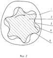
На фиг. 2 показано устройство по фиг. 1 с поворотом ключа до контакта. In FIG. 2 shows the device of FIG. 1 with a turn of the key to the contact.
На фиг. 3 показаны охватываемый и охватывающий элементы предлагаемой формы на примере головки болта в зацеплении с головкой ключа (нулевое положение). In FIG. 3 shows the male and female elements of the proposed shape using the example of a bolt head engaged with a key head (zero position).
На фиг. 4 показано устройство по фиг. 3 с поворотом ключа до контакта. In FIG. 4 shows the device of FIG. 3 with a turn of the key to the contact.
На фиг. 5 показана известная конструкция TORX деталь-ключ для охватываемого и охватывающего элементов (нулевое положение). In FIG. 5 shows the well-known TORX key construction for male and female elements (zero position).
На фиг. 6 показано устройство по фиг. 5 для углубления в головке винта с поворотом ключа до контакта. In FIG. 6 shows the device of FIG. 5 for deepening in the screw head with turning the key to the contact.
На фиг. 7 показано устройство по фиг. 5 для головки болта с поворотом ключа до контакта. In FIG. 7 shows the device of FIG. 5 for a bolt head with a turn of a key to contact.
На фиг. 8 показаны в сравнении профили криволинейных образующих предлагаемой и известной, фиг. 1 и 5 соответственно. In FIG. 8 shows in comparison profiles of curved generators of the proposed and known, FIG. 1 and 5, respectively.
Обозначения на чертежах. Designations in the drawings.
Фиг. 1. Стандартный ключ находится в углублении в торце головки винта. Головка винта 1, ключ 2, криволинейная образующая 3 углубления в торце головки 1, криволинейная образующая 4 ключа 2. Между образующими 3 и 4 имеется зазор 5. В окружном направлении по криволинейным образующим 3 и 4 зазор 5 попеременно уменьшается и увеличивается, уменьшается между образующими на вершинах выступов ключа и впадин углубления и увеличивается между ними по их боковым образующим 5. FIG. 1. The standard wrench is located in the recess in the end of the screw head. The screw head 1,
На фиг. 2 показана площадь контакта 6 между криволинейными поверхностями образующей 3 углубления в головке 1 и криволинейной поверхностью образующей 4 ключа 2, рабочее положение. In FIG. 2 shows the area of
На фиг. 3 показаны торцевая головка 7 ключа и головка болта 8, нулевое положение. Головка 7 ключа установлена на головке 8 болта. Криволинейная образующая 9 на головке 8 болта, криволинейная образующая 10 внутри торцевой головки 7 ключа, зазор 5. In FIG. 3 shows the
На фиг. 4 показана площадь контакта 11 между криволинейными поверхностями образующей 9 на головке болта 8 и криволинейной поверхностью образующей 10 торцевой головки 7. In FIG. 4 shows the area of contact 11 between the curved surfaces of the
Фиг. 5. Охватывающий и охватываемый элементы известной конструкции TORX - ключ установлен в углублении в головке винта. Головка винта 12, ключ 13, криволинейная образующая 14 в углублении головки 12, криволинейная образующая 15 ключа 13. Между образующими 14 и 15 в нулевом положении имеется зазор 16. Образующие 14 и 15 в известной конструкции подобны и относительно друг друга по всей окружности расположены эквидистантно, т.е. зазор 16 по всем точкам криволинейных выступов и впадин одинаков. FIG. 5. The male and female elements of the well-known TORX design - the key is installed in a recess in the screw head. The
На фиг. 6 показана точка контакта 17 между криволинейными поверхностями образующих 14 и 15. In FIG. 6 shows the
Фиг. 7. Головка болта 18 и торцевая головка ключа 19 известной конструкции TORX. Торцевая головка 19 надета на головку болта 18 и повернута на определенный угол до контакта. Криволинейная образующая 20 на головке болта 18, криволинейная образующая 21 на торцевой головке 19, точка контакта 22 криволинейных поверхностей образующих 20, 21. FIG. 7. The
Фиг. 8. Профиль предлагаемой криволинейной образующей 3 (фиг. 1), профиль известной криволинейной образующей 14 (фиг. 5) (охватывающие элементы) в сравнении. FIG. 8. The profile of the proposed curvilinear generatrix 3 (Fig. 1), the profile of the known curvilinear generatrix 14 (Fig. 5) (covering elements) in comparison.
Стрелками показано направление вращения элементов устройства для передачи крутящего момента. The arrows indicate the direction of rotation of the elements of the device for transmitting torque.
Пример работы устройства. An example of the operation of the device.
Постановочный инструмент в форме наконечника ключа 2 или торцевой головки 7 устанавливается в углубление в торце головки 1 винта или на головку 8 болта, после чего поворачивается по стрелке до контакта боковых криволинейных поверхностей 4 и 10 инструмента с ответными боковыми криволинейными поверхностями 3 и 9 на головке крепежной детали. Далее идет ввертывание резьбовой крепежной детали и затяжка. The setting tool in the form of a tip of a key 2 or an
Пример выполнения устройства, где охватывающим элементом является углубление в торце винта, а охватываемым -стандартный наконечник винтоверта. An example implementation of the device, where the female element is a recess in the end of the screw, and male standard tip of the screwdriver.
Углубление Dоп. = 6.8 мм, наконечник винтоверта Т 40. Коэффициенты выбираются из условий задачи и расчетом с использованием вышеприведенных формул
а = 0.03 Dоп. = 0.03 х 6.8 = 0.2 мм.Deepening Dop. = 6.8 mm, screwdriver tip T 40. Coefficients are selected from the conditions of the problem and by calculation using the above formulas
a = 0.03 Dop. = 0.03 x 6.8 = 0.2 mm.
L1 = (2n+1)a = (2х6 +1) 0.2 = 2.6 мм.L1 = (2n + 1) a = (2x6 +1) 0.2 = 2.6 mm.
L2 = 2n+1 = 12+1 = 13.L2 = 2n + 1 = 12 + 1 = 13.
K1 = (2n-1) a = (12-1) 0.2 = 2.2 мм.K1 = (2n-1) a = (12-1) 0.2 = 2.2 mm.
K2 = 2n-1=12 - 1= 11.K2 = 2n-1 = 12 - 1 = 11.
λ1= 1,1979 a = 1,1979×0,2 = 0,239 мм.
λ2= 1,1682 a = 1,1682×0,2 = 0,233 мм.
Подставляем в уравнения
Для выступов:

Для впадин:

При данных характеристиках параметрических уравнений получается криволинейная образующая с шестью симметрично расположенными по окружности попеременно чередующимися криволинейными выступами и впадинами. Длины криволинейных выступов и впадин равны между собой (относятся как 1:1).λ1 = 1.1979 a = 1.1979 × 0.2 = 0.239 mm.
λ2 = 1.1682 a = 1.1682 × 0.2 = 0.233 mm.
Substitute in the equation
For protrusions:
For troughs:
With these characteristics of the parametric equations, a curvilinear generatrix is obtained with six alternately alternating curvilinear protrusions and depressions symmetrically arranged around the circumference. The lengths of the curved protrusions and depressions are equal to each other (relate as 1: 1).
При взаимодействии боковых поверхностей криволинейных дуг ключа и детали площадь контакта их составляет около 1.0 мм2. В аналогичном типоразмере известной конструкции площадь контакта составляет около 0.2 мм2. Из этого следует, что в среднем площадь контакта криволинейной образующей головки детали предлагаемой формы с постановочным инструментом в 5-8 раз больше площади контакта головки известной конструкции.When the lateral surfaces of the curved arcs of the key and the part interact, their contact area is about 1.0 mm2 . In a similar size of the known construction, the contact area is about 0.2 mm2 . From this it follows that, on average, the contact area of the curved forming head of the part of the proposed form with the production tool is 5-8 times larger than the contact area of the head of a known design.
В настоящее время заводом АО "Этна" изготовлено несколько опытно-промышленных партий винтов с предлагаемой конструкцией углубления в головке и проведены испытания, в том числе в условиях конвейерной сборки автомобилей. Работа показала высокую прочность головок винтов и инструмента при затяжке детали и обеспечение высокопрочного резьбового соединения. At present, the Etna plant has manufactured several pilot industrial lots of screws with the proposed design of a recess in the head and tests have been carried out, including in the conditions of conveyor assembly of cars. The work showed high strength of the screw heads and tool when tightening the part and providing high-strength threaded connections.
Источники информации
1. Патент Великобритании N 1032144, МПК F 16 B 23/00 (аналог 1).Sources of information
1. British patent N 1032144, IPC F 16 B 23/00 (analogue 1).
2. Патент Великобритании N 1360644, МПК F 16 В 23/00 (аналог 2). 2. UK patent N 1360644,
3. Патент США N 3541624, МПК F 16 B 23/00 (аналог 3). 3. US patent N 3541624, IPC F 16 B 23/00 (analog 3).
4. Проспект фирмы "Bulten AB", Швеция, 1981 (прототип). 4. Prospectus of the company "Bulten AB", Sweden, 1981 (prototype).
5. Справочник по математике для инженеров и учащихся ВТУЗов, авторы И.Н. Бронштейн и К. А. Семендяев, М.: Наука, Главная редакция физико-математической литературы, 1980, с. 182-184. 5. Handbook of mathematics for engineers and students of technical colleges, authors I.N. Bronstein and K. A. Semendyaev, Moscow: Nauka, Main Edition of Physics and Mathematics, 1980, p. 182-184.
Claims (2)
Translated fromRussianx = 1,21•L1•cosφ-λ1•cos(L2•φ);
y = 1,21•L1sinφ-λ1•sin(L2•φ);
а форма впадин - уравнением гипоциклоиды:
x = 1,18•K1•cosφ+λ2•cos(K2•φ);
y = 1,18•K1•sinφ-λ2•sin(K2•φ);
где х и y - координаты;
L1, L2 и К1, К2 - коэффициенты соответствия количеству и размерам выступов и впадин;
φ аргумент (0 - 360o);
λ1 и λ2- коэффициенты, определяющие характер параметрических изменений выступов и впадин,
при этом коэффициенты соответствия количеству и размерам выступов и впадин определяются по формулам
L1 = (2 • n + 1) • a,
L2 = 2 • n + 1,
К1 = (2 • n - 1) • a,
K2 = 2 • n - 1,
где n - число, определяющее количество выступов (впадин) при построении;
a - коэффициент, определяющий совокупность элементов кривизны фигуры, a = 0.03 • Dоп., где Dоп. - диаметр описанной окружности,
а коэффициенты, определяющие характер параметрических изменений выступов и впадин определяются по формулам
λ1 = 1,1979•a,
λ2 = 1,1682•a.
2. Устройство по п. 1, отличающееся тем, что охватывающий элемент выполнен в виде фигурного углубления в торце головки винта или постановочного инструмента.1. A device for transmitting torque, made in the form of a female or male element in the form of alternately alternating curvilinear protrusions and depressions evenly spaced around the circumference of the element, characterized in that the shape of the generatrix of the curved protrusions and depressions of the female or male element is made in accordance with parametric equations, while the shape of the protrusions is made from a ratio defined by the equation of the epicycloid
x = 1.21 • L1 • cosφ-λ1 • cos (L2 • φ);
y = 1.21 • L1 sinφ-λ1 • sin (L2 • φ);
and the shape of the troughs is the equation of the hypocycloid:
x = 1.18 • K1 • cosφ + λ2 • cos (K2 • φ);
y = 1.18 • K1 • sinφ-λ2 • sin (K2 • φ);
where x and y are the coordinates;
L1 , L2 and K1 , K2 are the coefficients of correspondence to the number and size of protrusions and depressions;
φ argument (0 - 360o );
λ1 and λ2 are the coefficients that determine the nature of the parametric changes of the protrusions and depressions,
the coefficients of compliance with the number and size of protrusions and depressions are determined by the formulas
L1 = (2 • n + 1) • a,
L2 = 2 • n + 1,
K1 = (2 • n - 1) • a,
K2 = 2 • n - 1,
where n is a number that determines the number of protrusions (troughs) during construction;
a is a coefficient that determines the set of elements of the curvature of the figure, a = 0.03 • Dop., where Dop. - the diameter of the circumscribed circle,
and the coefficients that determine the nature of the parametric changes of the protrusions and depressions are determined by the formulas
λ1 = 1.1979 • a,
λ2 = 1.1682 • a.
2. The device according to claim 1, characterized in that the enclosing element is made in the form of a figured recess at the end of the screw head or staging tool.
Priority Applications (1)
| Application Number | Priority Date | Filing Date | Title |
|---|---|---|---|
| RU2000114870ARU2160396C1 (en) | 2000-06-14 | 2000-06-14 | Torque transmission device |
Applications Claiming Priority (1)
| Application Number | Priority Date | Filing Date | Title |
|---|---|---|---|
| RU2000114870ARU2160396C1 (en) | 2000-06-14 | 2000-06-14 | Torque transmission device |
Publications (1)
| Publication Number | Publication Date |
|---|---|
| RU2160396C1true RU2160396C1 (en) | 2000-12-10 |
Family
ID=20235961
Family Applications (1)
| Application Number | Title | Priority Date | Filing Date |
|---|---|---|---|
| RU2000114870ARU2160396C1 (en) | 2000-06-14 | 2000-06-14 | Torque transmission device |
Country Status (1)
| Country | Link |
|---|---|
| RU (1) | RU2160396C1 (en) |
Cited By (5)
| Publication number | Priority date | Publication date | Assignee | Title |
|---|---|---|---|---|
| RU2311569C2 (en)* | 2005-12-27 | 2007-11-27 | Открытое акционерное общество "Белебеевский завод "Автонормаль" | Threaded fastener with shaped head |
| RU2387533C1 (en)* | 2008-12-23 | 2010-04-27 | Открытое акционерное общество "Белебеевский завод "Автонормаль" | Installation tool for automatic assembly of threaded connections |
| US11234899B2 (en) | 2017-05-11 | 2022-02-01 | Scalpal Llc | Grasping facilitators and uses thereof and kits involving the same |
| RU2787107C2 (en)* | 2017-07-05 | 2022-12-28 | Хильти Акциенгезельшафт | Installation tool, set for installation tool system, and installation tool system |
| US11969864B2 (en) | 2017-05-11 | 2024-04-30 | Scalpal Llc | Multi-tier torque enhancer driver and/or receiver and method of using same |
Citations (3)
| Publication number | Priority date | Publication date | Assignee | Title |
|---|---|---|---|---|
| GB2260587A (en)* | 1991-10-16 | 1993-04-21 | Textron Inc | Elliptical lobed drive system |
| RU2010115C1 (en)* | 1991-05-05 | 1994-03-30 | Евгений Михайлович Казачков | Screw or wood screw head |
| RU2091617C1 (en)* | 1991-07-24 | 1997-09-27 | Адольф Вюрт ГмбХ унд Ко., КГ | Screw and its manipulator |
- 2000
- 2000-06-14RURU2000114870Apatent/RU2160396C1/ennot_activeIP Right Cessation
Patent Citations (3)
| Publication number | Priority date | Publication date | Assignee | Title |
|---|---|---|---|---|
| RU2010115C1 (en)* | 1991-05-05 | 1994-03-30 | Евгений Михайлович Казачков | Screw or wood screw head |
| RU2091617C1 (en)* | 1991-07-24 | 1997-09-27 | Адольф Вюрт ГмбХ унд Ко., КГ | Screw and its manipulator |
| GB2260587A (en)* | 1991-10-16 | 1993-04-21 | Textron Inc | Elliptical lobed drive system |
Cited By (8)
| Publication number | Priority date | Publication date | Assignee | Title |
|---|---|---|---|---|
| RU2311569C2 (en)* | 2005-12-27 | 2007-11-27 | Открытое акционерное общество "Белебеевский завод "Автонормаль" | Threaded fastener with shaped head |
| RU2387533C1 (en)* | 2008-12-23 | 2010-04-27 | Открытое акционерное общество "Белебеевский завод "Автонормаль" | Installation tool for automatic assembly of threaded connections |
| US11234899B2 (en) | 2017-05-11 | 2022-02-01 | Scalpal Llc | Grasping facilitators and uses thereof and kits involving the same |
| US11458071B2 (en) | 2017-05-11 | 2022-10-04 | Scalpal Llc | Torque enhancer device for grasping and tooling, and assemblies and uses thereof |
| US11944587B2 (en) | 2017-05-11 | 2024-04-02 | Scalpal Llc | Grasping facilitators and uses thereof and kits involving the same |
| US11963933B2 (en) | 2017-05-11 | 2024-04-23 | Scalpal Llc | Torque enhancer device for grasping and tooling, and assemblies and uses thereof |
| US11969864B2 (en) | 2017-05-11 | 2024-04-30 | Scalpal Llc | Multi-tier torque enhancer driver and/or receiver and method of using same |
| RU2787107C2 (en)* | 2017-07-05 | 2022-12-28 | Хильти Акциенгезельшафт | Installation tool, set for installation tool system, and installation tool system |
Similar Documents
| Publication | Publication Date | Title |
|---|---|---|
| CA3052755C (en) | Hex driver | |
| US4338037A (en) | Multiple jackscrew rod to crosshead mounting | |
| JP4431493B2 (en) | Lobe drive socket for fasteners | |
| CN113302024B (en) | Equipment for tightening threaded fasteners | |
| EP0670431A1 (en) | Screw and wrench for snugly-fitted tightenings | |
| JP2013014000A (en) | Spiral drive system for threaded fastener | |
| EP1371453B1 (en) | Asymmetric wrench and fastener system | |
| RU2160396C1 (en) | Torque transmission device | |
| US5452974A (en) | Deformable locking fastener system and method of use | |
| RU2199034C2 (en) | Torque transmission device | |
| CN113007203A (en) | Deformation expansion type split unilateral bolt fastener and mounting tool thereof | |
| JP2005042925A5 (en) | ||
| RU26089U1 (en) | TORQUE TRANSMISSION DEVICE | |
| CN211550223U (en) | Self-fixing bolt type fastener | |
| CN115023557B (en) | Double-nut type anti-loosening nut | |
| CN220769922U (en) | Anti-theft and anti-loose bolt and nut assembly | |
| CN219366543U (en) | Nut and bolt | |
| JPH0248224Y2 (en) | ||
| JP7573224B2 (en) | Fastener | |
| KR20080001759U (en) | Head structure of fastener | |
| RU26471U1 (en) | REPLACEABLE HEAD FOR SOCKET KEYS | |
| EP3690262B1 (en) | Fastener arrangement for establishing a screw connection | |
| RU26767U1 (en) | REPLACEABLE HEAD FOR SOCKET KEYS | |
| CN118423344A (en) | Self-locking nut for shear clip | |
| RU2621749C2 (en) | Method for tightening threaded connection |
Legal Events
| Date | Code | Title | Description |
|---|---|---|---|
| MM4A | The patent is invalid due to non-payment of fees | Effective date:20090615 |