RU2157504C1 - Jet projectile with detachable engine - Google Patents
Jet projectile with detachable engineDownload PDFInfo
- Publication number
- RU2157504C1 RU2157504C1RU99121043ARU99121043ARU2157504C1RU 2157504 C1RU2157504 C1RU 2157504C1RU 99121043 ARU99121043 ARU 99121043ARU 99121043 ARU99121043 ARU 99121043ARU 2157504 C1RU2157504 C1RU 2157504C1
- Authority
- RU
- Russia
- Prior art keywords
- pusher
- engine
- catcher
- angle
- disk
- Prior art date
Links
- 238000000926separation methodMethods0.000claimsabstractdescription22
- 238000003032molecular dockingMethods0.000claimsdescription6
- 230000002265preventionEffects0.000abstract1
- 239000000126substanceSubstances0.000abstract1
- 235000015842HesperisNutrition0.000description1
- 235000012633Iberis amaraNutrition0.000description1
- 230000015556catabolic processEffects0.000description1
- 230000000284resting effectEffects0.000description1
- 239000003381stabilizerSubstances0.000description1
- 230000007704transitionEffects0.000description1
Images
Landscapes
- Braking Arrangements (AREA)
Abstract
Description
Translated fromRussianПредлагаемое изобретение относится к каретной технике. The present invention relates to carriage equipment.
Известна конструкция реактивного снаряда с отделяемым двигателем [1], состоящим из устройства для стыковки разнокалиберных ступеней снаряда, содержащим переходный конический обтекатель с центральной трубой, охватывающей маршевую степень снаряда, и позволяющий двигателю скользить параллельно в направлении, противоположном маршевой ступени, и механизм разделения в виде щелевого канального устройства на конусной части обтекателя, сообщающегося с одной стороны с полостью маршевой ступени, а с другой с аэродинамическим потоком движущего снаряда. A known design of a missile with a detachable engine [1], consisting of a device for joining different stages of the projectile containing a transition conical fairing with a central tube covering the marching degree of the projectile, and allowing the engine to slide in parallel in the direction opposite to the marching stage, and the separation mechanism in the form slotted channel device on the conical part of the fairing, communicating on the one hand with the cavity of the marching stage, and on the other with the aerodynamic flow of the moving shell.
Данная конструкция разделительного устройства применима в неуправляемых реактивных снарядах, реактивной системы залпового огня (РСЗО), поскольку возникающие возмущения при разделении практически не влияют на точность попадания в цель, т.к. НУРСами работают по площадям, и не приемлема к зенитным управляемым реактивным снарядам (ракетам), поскольку полученные возмущения при отделении маршевой ступени от двигателя приведут к резкому изменению угла атаки, что приведет к поломке стабилизаторов в маршевой ступени, а также к выходу маршевой ступени из луча системы управления, что приведет к потере снаряда. This design of the separation device is applicable in unguided rockets, multiple launch rocket systems (MLRS), since the resulting disturbances during separation practically do not affect the accuracy of hitting the target, because NURSs operate over areas, and are not acceptable to anti-aircraft guided missiles (missiles), since the disturbances obtained when separating the marching stage from the engine will lead to a sharp change in the angle of attack, which will lead to breakdown of the stabilizers in the marching stage, as well as to the marching stage’s exit from the beam control system, which will lead to the loss of a projectile.
Известна конструкция реактивного снаряда с отделяемым двигателем [2], содержащий маршевую ступень, пристыкованный к ней двигатель большего калибра, устройство стыковки и механизм разделения ступеней. A known design of a missile with a detachable engine [2], containing the marching stage, a larger caliber engine docked to it, a docking device and a stage separation mechanism.
Устройство стыковки выполнено в виде фланца-диафрагмы с наружным кольцевым выступом и конической гайкой-обтекателем, торец кормы маршевой ступени выполнен в виде втулки с аналогичным зеркальным кольцевым выступом, кольцевые выступы фланца-диафрагмы и маршевой ступени состыкованы друг с другом посредством кольцевых секторных кулачков с трапециевидной наружной канавкой, опирающихся на коническую боковую поверхность диска, закрепленного на переднем конце толкателя механизма разделения, диск выполнен с Т-образными параллельными его боковой поверхности пазами, в которых размещены Т-образные приливы секторных кулачков, механизм разделения выполнен в виде толкателя, задний конец которого в виде полого поршня с обтюрирующими проточками и дном с дроссельными отверстиями установлен в корпусе натяжителя, при этом во внутренней полости поршня установлена втулка с электровоспламенителем и ограничителем, а между корпусом натяжителя и поршнем толкателя размещено запорное шариковое устройство. The docking device is made in the form of a diaphragm flange with an external annular protrusion and a conical fairing nut, the end of the stern of the march step is made in the form of a sleeve with a similar mirror annular protrusion, the annular protrusions of the diaphragm flange and the march step are joined to each other by means of ring sector cams with trapezoid outer groove resting on a conical lateral surface of the disk, mounted on the front end of the pusher of the separation mechanism, the disk is made with T-shaped parallel to it on the surface of the grooves in which the T-shaped tides of the sector cams are located, the separation mechanism is made in the form of a pusher, the rear end of which is in the form of a hollow piston with obturating grooves and a bottom with throttle openings in the tensioner housing, while a sleeve with an electric igniter and a limiter, and a locking ball device is placed between the tensioner body and the plunger piston.
Однако и данная конструкция реактивного снаряда при всей своей надежности и безотказности работы из-за несовершенства конструкции толкателя все-таки не исключает возможности получения больших возмущений, действующих на маршевую ступень при отделении двигателя из-за отскока толкателя с диском и удара его о кормовую часть маршевой ступени после срабатывания механизма разделения. However, this design of the missile, with all its reliability and reliability due to imperfections in the pusher design, still does not exclude the possibility of large disturbances acting on the marching stage when the engine is separated due to the rebound of the pusher with the disk and its impact on the aft part of the marching steps after triggering the separation mechanism.
Задачей предлагаемого изобретения является устранение указанных выше недостатков, а именно обеспечение надежного улавливания толкателя для исключения его отскока, и тем самым надежного предотвращения соударения при разделении ступеней. The objective of the invention is to eliminate the above disadvantages, namely, ensuring reliable capture of the pusher to prevent its rebound, and thereby reliably prevent collision during separation of the steps.
Указанная задача достигается тем, что в реактивном снаряде с отделяемым двигателем, содержащем маршевую ступень, пристыкованный к ней двигатель, устройство стыковки и механизм разделения ступеней, состоящий из толкателя с диском, натяжителя и электровоспламенителя, в механизме разделения на цилиндрической части толкателя перед диском выполнен опорный конический бурт, при этом в передней стенке натяжителя выполнен улавливатель, эквивалентный коническому бурту, причем угол наклона образующих конического бурта и улавливателя выполнен меньше угла трения, при этом расстояние между средними диаметрами конического бурта и улавливателя равно рабочему ходу толкателя. This task is achieved by the fact that in a rocket with a detachable engine containing a marching stage, an engine docked to it, a docking device and a stage separation mechanism consisting of a pusher with a disk, a tensioner and an electric igniter, a support is made in the separation mechanism on the cylindrical part of the pusher in front of the disk conical collar, while in the front wall of the tensioner is made a trap equivalent to a conical collar, and the angle of inclination of the generators of the conical collar and catcher is made enshe friction angle, the distance between the average diameter of the conical collar and trap equal working stroke of the pusher.
Сущность предлагаемого изобретения заключается в том, что данная конструкция реактивного снаряда обеспечивает надежное разделение ступеней в заданный момент времени с минимальными возмущениями, действующими на маршевую ступень при отделении двигателя. The essence of the invention lies in the fact that this missile design provides reliable separation of stages at a given point in time with minimal disturbances acting on the march stage during engine separation.
Существо изобретения поясняется чертежами:
на фиг. 1 - изображен реактивный снаряд;
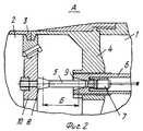
на фиг. 2 - вид А - конструкция механизма разделения разнокалиберных ступеней снаряда, где:
1 - отделяемый двигатель
2 - маршевая ступень реактивного снаряда
3 - устройство стыковки
4 - механизм разделения ступеней
5 - толкатель
6 - натяжитель
7 - электровоспламенитель
8 - конический бурт
9 - улавливатель
10 - диск
Б - рабочий ход толкателя
Устройство и работа механизма разделения заключается в следующем: в реактивном снаряде маршевая ступень 2 объединяется с отделяемым двигателем 1 через устройство стыковки 3 и механизм разделения ступеней 4, состоящий из толкателя 5 с коническим буртом 8, натяжителя 6 с улавливателем 9 и электровоспламенителя 7.The invention is illustrated by drawings:
in FIG. 1 - shows a missile;
in FIG. 2 - view A - design of the mechanism for the separation of different stages of the shell, where:
1 - detachable engine
2 - marching stage of a rocket
3 - docking device
4 - stage separation mechanism
5 - pusher
6 - a tensioner
7 - electric igniter
8 - conical shoulder
9 - catcher
10 - disk
B - stroke of the pusher
The device and the operation of the separation mechanism is as follows: in a rocket, the
При полете реактивного снаряда в момент окончания работы двигателя 1 с бортовой аппаратуры снаряда (например от инерционного замыкателя) подается напряжение на электровоспламенитель 7, срабатывание которого приводит к втягиванию толкателя 5 с диском 10 в натяжитель, при этом толкатель 5 своим коническим буртом 8 входит в улавливатель 9 натяжителя 6, надежно удерживаясь (заклинивая) в нем, поскольку угол наклона образующих конического бурта и улавливателя выполнен меньше угла трения, в этот момент происходит разделение ступеней. When a missile is flying at the moment of engine 1’s termination of the projectile’s onboard equipment (for example, from an inertial contactor), voltage is supplied to the electric igniter 7, the operation of which causes the pusher 5 with the
При выполнении угла наклона образующих больше угла трения произойдет отскок и удар диском 10 по корме маршевой ступени, что недопустимо. When the angle of inclination of the generators is greater than the angle of friction, a rebound and a blow by the
Расстояние между средними диаметрами конического бурта и улавливателя должно быть равно рабочему ходу толкателя. The distance between the average diameters of the conical shoulder and the trap should be equal to the working stroke of the pusher.
При условии если рабочий ход мал, то не произойдет разделение ступеней, поскольку диск не переместится в свободный объем перед натяжителем, что недопустимо. При условии, если рабочий ход больше, это приведет к необоснованному увеличению габаритов и массы механизма разделения, кроме того, увеличит время разделения, что также недопустимо. Provided that the working stroke is small, the separation of the steps will not occur, since the disk will not move into the free volume in front of the tensioner, which is unacceptable. Provided that the stroke is longer, this will lead to an unreasonable increase in the size and mass of the separation mechanism, in addition, increase the separation time, which is also unacceptable.
Источники информации
1. Заявка Франции N 2629583, публ. 06.10.89, МПК F 42 B 15/00 - аналог.Sources of information
1. Application of France N 2629583, publ. 10.10.89, IPC F 42 B 15/00 - analogue.
2. Патент России N 2133445 от 20.07.99, БИ N 20, 1999 - прототип. 2. Patent of Russia N 2133445 from 07/20/99, BI N 20, 1999 - prototype.
Claims (1)
Translated fromRussianPriority Applications (1)
| Application Number | Priority Date | Filing Date | Title |
|---|---|---|---|
| RU99121043ARU2157504C1 (en) | 1999-10-05 | 1999-10-05 | Jet projectile with detachable engine |
Applications Claiming Priority (1)
| Application Number | Priority Date | Filing Date | Title |
|---|---|---|---|
| RU99121043ARU2157504C1 (en) | 1999-10-05 | 1999-10-05 | Jet projectile with detachable engine |
Publications (1)
| Publication Number | Publication Date |
|---|---|
| RU2157504C1true RU2157504C1 (en) | 2000-10-10 |
Family
ID=20225558
Family Applications (1)
| Application Number | Title | Priority Date | Filing Date |
|---|---|---|---|
| RU99121043ARU2157504C1 (en) | 1999-10-05 | 1999-10-05 | Jet projectile with detachable engine |
Country Status (1)
| Country | Link |
|---|---|
| RU (1) | RU2157504C1 (en) |
Cited By (1)
| Publication number | Priority date | Publication date | Assignee | Title |
|---|---|---|---|---|
| RU2843385C1 (en)* | 2024-06-05 | 2025-07-14 | Анатолий Михайлович Криштоп | Combined jet aviation ammunition (cjaa), method of cjaa functioning and method of enemy air defense means destruction using two cjaa (embodiments) |
Citations (6)
| Publication number | Priority date | Publication date | Assignee | Title |
|---|---|---|---|---|
| US5020436A (en)* | 1989-07-24 | 1991-06-04 | General Dynamics Corp., Air Defense Systems Div. | Booster retarding apparatus |
| FR2629583B1 (en)* | 1988-03-30 | 1993-06-18 | Aerospatiale | AIRCRAFT PROVIDED WITH AT LEAST ONE WIDTHABLE PROPELLER |
| RU2064655C1 (en)* | 1991-07-18 | 1996-07-27 | Государственный научно-исследовательский институт авиационных систем | Aerodynamic canard configuration guides missile |
| GB2314612A (en)* | 1996-06-28 | 1998-01-07 | Buck Chem Tech Werke | A missile for combating moving targets |
| RU2105949C1 (en)* | 1995-06-07 | 1998-02-27 | Конструкторское бюро приборостроения | Jet projectile |
| RU2133445C1 (en)* | 1998-03-25 | 1999-07-20 | Конструкторское бюро приборостроения | Jet projectile with separated engine |
- 1999
- 1999-10-05RURU99121043Apatent/RU2157504C1/enactive
Patent Citations (6)
| Publication number | Priority date | Publication date | Assignee | Title |
|---|---|---|---|---|
| FR2629583B1 (en)* | 1988-03-30 | 1993-06-18 | Aerospatiale | AIRCRAFT PROVIDED WITH AT LEAST ONE WIDTHABLE PROPELLER |
| US5020436A (en)* | 1989-07-24 | 1991-06-04 | General Dynamics Corp., Air Defense Systems Div. | Booster retarding apparatus |
| RU2064655C1 (en)* | 1991-07-18 | 1996-07-27 | Государственный научно-исследовательский институт авиационных систем | Aerodynamic canard configuration guides missile |
| RU2105949C1 (en)* | 1995-06-07 | 1998-02-27 | Конструкторское бюро приборостроения | Jet projectile |
| GB2314612A (en)* | 1996-06-28 | 1998-01-07 | Buck Chem Tech Werke | A missile for combating moving targets |
| RU2133445C1 (en)* | 1998-03-25 | 1999-07-20 | Конструкторское бюро приборостроения | Jet projectile with separated engine |
Cited By (1)
| Publication number | Priority date | Publication date | Assignee | Title |
|---|---|---|---|---|
| RU2843385C1 (en)* | 2024-06-05 | 2025-07-14 | Анатолий Михайлович Криштоп | Combined jet aviation ammunition (cjaa), method of cjaa functioning and method of enemy air defense means destruction using two cjaa (embodiments) |
Similar Documents
| Publication | Publication Date | Title |
|---|---|---|
| JP3065669B2 (en) | Aerodynamically stable bullet system for use against underwater targets. | |
| US3903804A (en) | Rocket-propelled cluster weapon | |
| US4712465A (en) | Dual purpose gun barrel for spin stabilized or fin stabilized projectiles and gun launched rockets | |
| EP0597142B1 (en) | A practice projectile | |
| US4676136A (en) | Apparatus for recoilless firing of projectiles from a lauching tube | |
| JPS6136159B2 (en) | ||
| US4444117A (en) | Stacked tube submunition dispenser | |
| US3167016A (en) | Rocket propelled missile | |
| KR100796706B1 (en) | Artillery projectile with exchangeable payload | |
| US7448324B1 (en) | Segmented rod projectile | |
| US5804759A (en) | Hunting bullet having a telescoping flechette and comprising a sub-projectile connected to a launcher | |
| EP0694156B1 (en) | A method and an apparatus for spreading warheads | |
| US4430943A (en) | Fin-stabilized projectile having a sabot base and forming a practice projectile | |
| US4135686A (en) | Device for starting rocket-driven missiles | |
| EP0079513A1 (en) | Carrier missile containing a terminally guided projectile | |
| US4939997A (en) | Article of ammunition | |
| US2946261A (en) | Peripheral nozzle spinner rocket | |
| RU2133445C1 (en) | Jet projectile with separated engine | |
| US5363766A (en) | Remjet powered, armor piercing, high explosive projectile | |
| RU2157504C1 (en) | Jet projectile with detachable engine | |
| FI111296B (en) | Controlled subdivision holder for sub-caliber projectiles | |
| US3705550A (en) | Solid rocket thrust termination device | |
| RU2222771C1 (en) | Rocket | |
| US4307651A (en) | Rocket in-tube spin device and rear sabot | |
| SE501082C2 (en) | Method and apparatus for giving an airborne combat section a desired pattern of movement |
Legal Events
| Date | Code | Title | Description |
|---|---|---|---|
| PC43 | Official registration of the transfer of the exclusive right without contract for inventions | Effective date:20161130 |