RU2153893C2 - Device for needle drawing-in - Google Patents
Device for needle drawing-inDownload PDFInfo
- Publication number
- RU2153893C2 RU2153893C2RU97103953/14ARU97103953ARU2153893C2RU 2153893 C2RU2153893 C2RU 2153893C2RU 97103953/14 ARU97103953/14 ARU 97103953/14ARU 97103953 ARU97103953 ARU 97103953ARU 2153893 C2RU2153893 C2RU 2153893C2
- Authority
- RU
- Russia
- Prior art keywords
- needle
- piston
- fastening
- syringe
- hollow
- Prior art date
Links
- 230000008878couplingEffects0.000claimsabstractdescription4
- 238000010168coupling processMethods0.000claimsabstractdescription4
- 238000005859coupling reactionMethods0.000claimsabstractdescription4
- 238000006073displacement reactionMethods0.000claimsabstractdescription3
- 239000012530fluidSubstances0.000claimsdescription9
- 238000007789sealingMethods0.000claimsdescription9
- 239000007788liquidSubstances0.000claimsdescription5
- 230000006835compressionEffects0.000claimsdescription4
- 238000007906compressionMethods0.000claimsdescription4
- 230000002093peripheral effectEffects0.000claimsdescription2
- 238000006243chemical reactionMethods0.000claims1
- 238000007373indentationMethods0.000claims1
- 239000003814drugSubstances0.000abstractdescription4
- 238000012856packingMethods0.000abstract2
- 230000000694effectsEffects0.000abstract1
- 239000007924injectionSubstances0.000abstract1
- 238000002347injectionMethods0.000abstract1
- 239000000126substanceSubstances0.000abstract1
- 239000008280bloodSubstances0.000description5
- 210000004369bloodAnatomy0.000description5
- 239000012634fragmentSubstances0.000description4
- 210000004204blood vesselAnatomy0.000description2
- 229940079593drugDrugs0.000description2
- 208000014674injuryDiseases0.000description2
- 208000012260Accidental injuryDiseases0.000description1
- 208000027418Wounds and injuryDiseases0.000description1
- 230000001154acute effectEffects0.000description1
- 238000012864cross contaminationMethods0.000description1
- 230000006378damageEffects0.000description1
- 210000000245forearmAnatomy0.000description1
- 238000001802infusionMethods0.000description1
- 238000009434installationMethods0.000description1
- 238000012986modificationMethods0.000description1
- 230000004048modificationEffects0.000description1
- 230000001681protective effectEffects0.000description1
- 230000000717retained effectEffects0.000description1
- 238000005070samplingMethods0.000description1
Images


Landscapes
- Infusion, Injection, And Reservoir Apparatuses (AREA)
Abstract
Description
Translated fromRussianИзобретение связано с усовершенствованиями, относящимися к устройствам втягивания, используемым в устройствах для введения и взятия жидкостей, причем указанные устройства установлены для обеспечения втягивания полой иглы в корпус после использования. Такие устройства используются во многих областях медицины для введения лекарственных препаратов или для капельных вливаний в кровеносные сосуды, или взятия образцов жидкости, как, например, крови у пациентов. The invention relates to improvements related to retraction devices used in devices for introducing and collecting liquids, said devices being installed to retract the hollow needle into the body after use. Such devices are used in many fields of medicine for administering drugs or for drip infusion into blood vessels, or for taking fluid samples, such as, for example, blood from patients.
Известно, что существует большое разнообразие устройств для введения и взятия жидкостей, используемых в области медицины с целью введения лекарственных препаратов, и аналогичных устройств для взятия образцов крови, включая устройства, используемые для взятия более чем одного образца крови у пациента в течение периода времени. It is known that there is a wide variety of devices for administering and collecting liquids used in the medical field for administering drugs, and similar devices for collecting blood samples, including devices used to take more than one blood sample from a patient over a period of time.
Важно, чтобы иглы подобных устройств, которые часто подлежат выбрасыванию после однократного использования, приводились в нерабочее состояние для предотвращения случайной травмы или повторного использования с существенным риском перекрестного заражения. It is important that the needles of such devices, which are often discarded after a single use, are rendered inoperative to prevent accidental injury or reuse with a significant risk of cross-contamination.
Известны шприцы, снабженные защитными приспособлениями различных видов, которые автоматически вводятся в действие для изоляции иглы после использования, а также шприцы, в которых игла автоматически втягивается в корпус устройства после использования. Known syringes are equipped with protective devices of various kinds that are automatically activated to isolate the needle after use, as well as syringes in which the needle is automatically retracted into the body of the device after use.
Изобретение раскрывает устройство для введения и взятия жидкости, имеющее узел для втягивания иглы, приспособленный для втягивания полой иглы после использования, содержащий полую корпусную часть, снабженную на одном из его концов торцевой стенкой, имеющей крепежную часть, включающую канал для иглы и полую иглу, имеющую крепежное средство и способную перемещаться между первым положением, в котором ведущая торцевая часть иглы выступает из передней торцевой части указанной крепежной части, и вторым положением, в котором игла удаляется внутрь полой корпусной части, причем указанное крепежное средство включает упругое средство, действие которого направлено на смещение иглы во второе, удаленное положение, а указанная игла снабжена утолщенной частью в участке, отделенном от ее ведущей торцевой части, с наличием там втягивающего средства для удерживания иглы в ее первом положении до окончания использования, причем указанное втягивающее средство включает комбинацию уплотнительного кольца, расположенного в окружающей борозде в указанной утолщенной части, и примыкающего к концу муфты, которая может вдавливаться вперед для смещения уплотнительного кольца таким образом, чтобы обеспечить возможность перемещения иглы из ее первого положения в ее второе положение под влиянием указанного упругого средства. The invention discloses a device for introducing and collecting fluid, having a node for retracting the needle, adapted to retract the hollow needle after use, comprising a hollow body portion provided at one of its ends with an end wall having a fastening portion including a channel for the needle and a hollow needle having fastening means and capable of moving between a first position in which the leading end part of the needle protrudes from the front end part of the specified fastening part and a second position in which the needle is removed the morning of the hollow body part, wherein said fastening means includes elastic means, the action of which is aimed at shifting the needle to a second, remote position, and said needle is provided with a thickened part in a section separated from its leading end part, with the presence of retracting means therein for holding the needle in its first position before the end of use, and the specified retractor includes a combination of a sealing ring located in the surrounding groove in the specified thickened part, and adjacent to the end of the coupling, which can be pressed forward to displace the sealing ring in such a way as to allow the needle to move from its first position to its second position under the influence of the specified elastic means.
Муфта может фиксироваться для предотвращения смещения назад, когда игла находится в своем первом положении, с помощью выступа, примыкающего к фланцу у переднего конца корпусной части. The sleeve can be locked to prevent backward movement when the needle is in its first position with a protrusion adjacent to the flange at the front end of the body portion.
Упругим средством может быть пружина сжатия, расположенная между поверхностью противодействия, направленного вперед, снабженной крепежной частью, и поверхностью противодействия, направленного назад, снабженной передним концом утолщенной части. The elastic means may be a compression spring located between the counteracting surface directed forward provided with a fastening part and the counteracting surface directed backward provided with a front end of the thickened part.
Когда игла находится в своем первом положении, уплотнительное кольцо может сдавливаться между утолщенной частью и крепежной частью, которая обеспечивает освобожденную часть у своего переднего конца для принятия уплотнительного кольца, когда оно смещается. When the needle is in its first position, the o-ring can be squeezed between the thickened part and the fastening part, which provides the released part at its front end to accept the o-ring when it is displaced.
Устройством для введения и взятия жидкости может быть шприц, имеющий поршень, который при нажатии может перемещаться по корпусной части для выпуска содержащейся в ней жидкости через иглу, причем поршень изготовлен в форме трубки, имеющей закрытые концы, передний из которых снабжен запорным элементом, отделяемым от конца путем сцепления с муфтой, когда поршень при нажатии перемещается в крайнее положение, образуя отверстие в конце, через которое может пройти игла для вхождения внутрь поршня, когда он переходит в свое второе положение. A device for introducing and collecting fluid can be a syringe having a piston, which when pressed can move along the body to release the fluid contained in it through a needle, the piston being made in the form of a tube having closed ends, the front of which is equipped with a locking element that is detachable from the end by engagement with the clutch, when the piston, when pressed, moves to the extreme position, forming a hole in the end through which the needle can pass to enter the piston when it moves to its second position.
Расположение крепежной части может быть эксцентричным и смещенным по направлению к периферийной кромке корпусной части. The location of the mounting portion may be eccentric and biased towards the peripheral edge of the housing portion.
Поперечные сечения корпусной части и поршня могут быть такими, чтобы исключить неправильную сборку относительно положения запорного элемента. Cross sections of the body and piston may be such as to prevent improper assembly relative to the position of the locking element.
Поперечные сечения корпусной части и поршня могут быть такими, чтобы при обеспечении возможности сборки в более чем одном вращательных положениях относительно друг друга, гарантировалась их правильная работа за счет наличия на конце поршня более одного запорного элемента. The cross sections of the housing and the piston can be such that, while allowing assembly in more than one rotational position relative to each other, their correct operation is guaranteed due to the presence of more than one locking element at the end of the piston.
Корпусная часть и поршень могут в сечении иметь форму, эллипса с двумя разделенными друг от друга запорными элементами на конце поршня. The casing and the piston may be in cross section in the form of an ellipse with two locking elements separated from each other at the end of the piston.
Полая корпусная часть может не предназначаться для приема поршня; и для обеспечения втягивания иглы в устройство при необходимости в корпусную часть может вставляться подобный поршню инструмент. The hollow body may not be suitable for receiving the piston; and to ensure that the needle is drawn into the device, if necessary, a piston-like tool can be inserted into the body.
Муфта может располагаться в углублении, к которому обеспечен доступ части уменьшенного размера на переднем конце инструмента, приспособленного для вхождения в углубление и зацепления с муфтой. Это предотвращает преждевременное втягивание иглы. The clutch may be located in the recess, which is provided with access to parts of a reduced size at the front end of the tool, adapted to enter the recess and engage with the clutch. This prevents the needle from retracting prematurely.
В соответствии с изобретением также предложен одноразовый шприц с эксцентрической иглой, имеющий корпусную часть и поршень, передний конец которого включает запорный элемент, приспособленный смещаться в конце продвижения поршня для обеспечения возможности устройству втягивания иглы удалить иглу и поместить ее внутри поршня для удаления. The invention also provides a disposable syringe with an eccentric needle having a body and a piston, the front end of which includes a locking element adapted to move at the end of the piston advancement to allow the needle retractor to remove the needle and place it inside the piston for removal.
Поперечные сечения корпусной части и поршня могут быть такими, чтобы исключить неправильную сборку относительно положения запорного элемента. Cross sections of the body and piston may be such as to prevent improper assembly relative to the position of the locking element.
Поперечные сечения корпусной части и поршня могут быть такими, чтобы при обеспечении возможности сборки в более чем одно вращательных положениях относительно друг друга, гарантировалась их правильная работа за счет наличия на конце поршня более одного запорных элементов. Cross sections of the body and piston may be such that, while being able to assemble in more than one rotational position relative to each other, their correct operation is guaranteed due to the presence of more than one locking element at the end of the piston.
Корпусная часть и поршень могут в сечении иметь форму эллипса с двумя разделенными друг от друга запорными элементами, на конце поршня. The body part and the piston may be in cross section in the form of an ellipse with two locking elements separated from each other, at the end of the piston.
Также в соответствии с настоящим изобретением, предложена шприцевая система, включающая набор шприцевых цилиндров с совместно функционирующими поршнями, включающими цилиндры и поршни различной емкости, причем каждый цилиндр приспособлен для приема устройств для крепежа и втягивания иглы, и каждый поршень совместно функционирует с цилиндром таким образом, чтобы составить часть, совместно функционирующую с устройством для крепежа и втягивания иглы, совмещенным с ней на сборке поршня и цилиндра и устройстве для крепежа и втягивания иглы, по крайней мере одного набора с эксцентричной установкой для обеспечения возможности канюлирования под острым углом. Also in accordance with the present invention, there is provided a syringe system comprising a set of syringe cylinders with jointly functioning pistons, including cylinders and pistons of different capacities, each cylinder being adapted to receive devices for fastening and retracting the needle, and each piston cooperates with the cylinder in such a way to make up the part that works together with the device for fastening and retracting the needle, combined with it on the assembly of the piston and cylinder and the device for fastening and retracting the needle at least one set with an eccentric installation to enable cannulation at an acute angle.
Далее описаны два примера устройства в соответствии с изобретением. Очевидно, что описание, которое следует читать со ссылкой на чертежи, приводится только в качестве примера, а не как ограничивающее условие. Two examples of the device according to the invention are described below. It is obvious that the description, which should be read with reference to the drawings, is given only as an example, and not as a limiting condition.
Краткое описание чертежей
Фиг. 1 является видом сбоку шприца в соответствии с изобретением в нерабочем состоянии.Brief Description of the Drawings
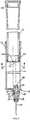
FIG. 1 is a side view of a syringe according to the invention inoperative.
Фиг. 2 является продольным сечением шприца по линии II-II фиг. 1 в увеличенном масштабе. FIG. 2 is a longitudinal section of a syringe along line II-II of FIG. 1 on an enlarged scale.
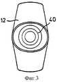
Фиг. 3 является видом шприца с торца. FIG. 3 is an end view of a syringe.
Фиг. 4 является сечением по линиям IV-IV на фиг. 2. FIG. 4 is a section along lines IV-IV in FIG. 2.
Фиг. 5 является видом с противоположного торца, являющегося видом с игольного торца. FIG. 5 is a view from the opposite end, which is a view from the needle end.
Фиг. 6 является сечением, аналогичным фиг. 1, иллюстрирующим промежуточную стадию при нажатии поршня шприца. FIG. 6 is a section similar to FIG. 1 illustrating an intermediate step by pressing a syringe plunger.
Фиг. 7 является аналогичным видом, иллюстрирующим завершение этапа нажатия. FIG. 7 is a similar view illustrating the completion of a pressing step.
Фиг. 8, 9 и 10 являются видами фрагментов в увеличенном мас штабе соответственно фрагментам 2, 6 и 7. FIG. 8, 9, and 10 are types of fragments on an enlarged scale, respectively, to
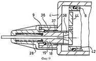
Фиг. 11 является фрагментом продольного среза устройства для введения и взятия жидкости, используемого для взятия проб крови. FIG. 11 is a fragment of a longitudinal section of a device for introducing and collecting fluid used for sampling blood.
Фиг. 12 является аналогичным видом со вставленным в инструмент приспособлением для втягивания иглы. FIG. 12 is a similar view with the needle retractor inserted in the tool.
Фиг. 13 является видом устройства с его иглой во втянутом состоянии. FIG. 13 is a view of a device with its needle retracted.
На фиг. 1 показан одноразовый шприц 2, содержащий полую корпусную часть 4, позади которой (верхний конец в проекции, показанной на фиг. 1) выступает поршень 6. В нижнем конце корпусной части 4 имеется крепежная часть 8 для иглы 10, имеющая сквозной канал, у внутреннего конца которого имеется кольцевидный бортик 9. In FIG. 1 shows a disposable syringe 2 containing a
Полая корпусная часть 4, которая прозрачна, для удобства проградуирована в миллиметрах и снабжена выступами 12 для захвата пальцами обычным образом. Корпусная часть 4 имеет несколько расширяющуюся наружу концевую часть 15. Крепежная часть 8 фиксируется к торцевой стенке 14 корпусной части 4 в эксцентрическом положении 16 (см. фиг. 2) для облегчения пользования шприцем при обеспечении возможности введения иглы 10 в ткань или кровеносный сосуд под любым желаемым острым углом. The
Внутренний конец иглы 10 соединяется с втулкой 18, имеющей кольцевую борозду 19, в которой располагается уплотнительное кольцо 20. Втулка 18 скреплена с иглой, образуя с ней единый комплекс. The inner end of the
Как лучше всего видно из фиг. 3-5, корпусная часть 4 и поршень 6 в поперечном сечении имеют эллипсоидную форму, которая предотвращает любую тенденцию нежелательного относительного вращения частей. As best seen from FIG. 3-5, the
Крепежная часть 8 обеспечивает путь прохождения для иглы 10 и первую поверхность противодействия 26 для пружины сжатия 28, окружающей иглу. Вторая поверхность противодействия 30 находится на переднем конце втулки 18. В сборе пружина 28 находится в почти полностью сжатом состоянии между поверхностями 26 и 30 и удерживается в этом состоянии зацеплением уплотнительного кольца 20, которое сдавлено между кольцевой частью стенки 32 крепежной части 8 и ее бороздой 19, с торцевой поверхностью 34 муфты 36, окружающей втулку 18, и включающий в ее заднем конце удлинение 38, образованное выступами, которые направлены внутрь полой корпусной части 4, в состоянии перед использованием, показанном на фиг. 2 и 8. The
Как видно из фиг. 8, передняя поверхность уплотнительного кольца 20 снабжена кольцевой камерой 35. As can be seen from FIG. 8, the front surface of the o-
Муфта 36 имеет выступ 37, который входит в зацепление с кольцевым фланцем 39 на переднем конце корпуса 4, для предотвращения смещения муфты 36 назад от ее первоначального положения, показанного на фиг. 2 и 8. The
Поршень 6 полый, задний конец которого закрыт с помощью крышки 40. Следует отметить, что самый большой диаметр поршня в его заднем конце 13, то есть в части, примыкающей к концевой крышке 40, а по направлению к корпусной части поршень сужается. The
Другой конец поршня имеет конструкцию, обеспечивающую прием запорного элемента 42, который входит в плотное зацепление в поршне для образования торцевой стенки, имеющей две зоны 44, определенные линиями непрочности 46 таким образом, чтобы они легко удалялись при контакте с выступами удлинения втулки 38, объяснение чего будет дано ниже. Обеспечение двух таких зон 44 устраняет необходимость контроля положения отходящей иглы 10 во время сборки. The other end of the piston is designed to receive the
При работе шприц для удобства обычным образом заполняют жидкостью для приведения его в состояние готовности к применению, при котором поршень 6 на небольшое расстояние вводится внутрь корпусной части 4, как показано на фиг. 2. Таким образом, запорный элемент 42 поршня действует в качестве уплотняющей прокладки для жидкого содержимого корпусной части. During operation, for convenience, the syringe is usually filled with liquid to bring it into a state of readiness for use, in which the
При начале работы и смещении поршня 6 вперед (или вниз в проекции, показанной на фиг. 1), продвигающаяся торцевая стенка элемента 42 выталкивает жидкость через иглу 10. На фиг. 9 показано положение частей непосредственно перед завершением выталкивания жидкости. Видно, что торцевая стенка элемента 42 вошла в контакт с выступами удлинения 38 втулки 36, и вызвала смещение элемента 36 вперед, как показано на фиг. 9. Однако жидкость еще может проходить из корпусной части 6 в иглу 10 вследствие наличия зазоров между выступами удлинения 38 элемента 36. Как показано на фиг. 10, перемещение втулки 36, вследствие ее контакта с уплотнительным кольцом 20, которое расположено в борозде 19, вызвало также перемещение вперед кольцевой втулки 18, сдавливающей затем пружину 28 до состояния полного сжатия. Кроме того, это перемещение вызывает освобождение уплотнительного кольца 20 от удерживания в борозде 19 кольцевой частью 32 и его смещение до вхождения в кольцевую камеру 35, где оно принимается через стенку 9 крепежной части 8. Таким образом устраняется ограничение, действующее на игольную торцевую часть 18. Теперь полностью сжатая пружина 28 не имеет больше ограничений и быстро расширяется, приводя в движение игольную торцевую часть 18, а следовательно, саму иглу, назад. Втулка 36 и ее выступы 38 имеют вместе такую длину, которая обеспечивает их выпячивание в полую внутреннюю часть корпусной части 4. Поэтому выступы создают зону давления на зону 44 таким образом, чтобы произвести сдвиг линии непрочности 46. После этого игла 10 свободно проходит через втулку 36 в полую внутреннюю часть поршня 6 таким образом, что она удаляется и становится недоступной для потенциальных повторных пользователей шприца. Следует понять, что на практике поршень 6 не может быть легко извлечен из корпусной части 4 для облегчения доступа к игле, поскольку кольцевая часть 13 поршня 6 плотно вклинивается в расширяющуюся концевую часть 15 корпусной части 4 и, следовательно, оказывает сопротивление при извлечении. At the start of operation and the displacement of the
Поэтому теперь шприц можно выбросить без опасности для лиц, которые в последующем будут контактировать с иглой. Therefore, now the syringe can be thrown out without danger to persons who will subsequently come into contact with the needle.
На фиг. 11 показан вид фрагмента устройства втягивания иглы, обозначенного цифрой 48, который используется в устройстве для повторного взятия образцов крови. Устройство включает кожух 50 с открытым торцом, в который вставляется удаленная трубка 52 типа трубки, продающейся под зарегистрированной торговой маркой "Vacutainer", имеющей диафрагму 54, которая протыкается задней концевой частью 56 полой иглы с двумя концами 58 таким образом, чтобы обеспечить возможность набирать образец в трубку 52. Для удобства игла 58 может оставаться неподвижной в течение периода времени, который может быть необходимым для взятия серии проб, но при завершении серии иглу нужно удалить и после этого возникают факторы риска, связанные с повторным использованием иглы. In FIG. 11 is a view of a fragment of a needle retractor, indicated by the
Устройство для втягивания иглы, показанное на фиг. 11-13, во многом аналогично показанному на фиг. 1-10, причем одинаковые части обозначены одинаковыми цифрами. The needle retractor shown in FIG. 11-13, in much the same way as shown in FIG. 1-10, and the same parts are denoted by the same numbers.
Как упомянуто выше, игла 58 имеет два конца и проходит через кольцевую втулку 18. As mentioned above, the
Углубленная часть 82 образована на передней стенке кожуха 50, который имеет поверхность 86, в которую упирается удаленная трубка 52 при обычном использовании. Таким обрезом, при обычном использовании, как будет показано, контакт между трубкой 52 и выступами 38 отсутствует. A recessed
На фиг. 12 показано средство, с помощью которого игла 58 может втягиваться из рабочего состояния в положение, при котором она не может снова использоваться и не может вызвать травму контактирующих с ней людей. In FIG. 12 shows a means by which the
Таким образом, после взятия последней пробы, когда необходимо извлечь иглу из предплечья пациента, в кожух 50 вставляется инструмент 88, как показано на фиг. 12. Инструмент 88 содержит подобную поршню полую корпусную часть 90 и кольцевой выступ или горловину 92, которая окружена поверхностью уступа 94. Горловина 92 имеет круглое отверстие 96. Когда инструмент 88 вставляется в кожух 50, часть конца иглы 56 входит в отверстие 96 горловины 92, а сама горловина входит в углубление 82 в кожухе 50. Поверхность передней кромки горловины 92 вступает в контакт с выступами 38, и продолжающееся воздействие давления, прикладываемого для движения инструмента вперед, как показано на фиг. 12, вызывает перемещение вперед втулки 36 для смещения уплотнительного кольца 20 и освобождения иглы 58 для ее последующего сброса в корпус инструмента 88. Кольцевой зажим 98, защелкивающийся вокруг инструмента 88, гарантирует то, что инструмент не будет случайно извлечен из кожуха 50 до его безопасного удаления. Thus, after taking the last sample, when it is necessary to remove the needle from the patient's forearm, a
Как определено следующей ниже формулой изобретения, в пределах объема настоящего изобретения возможны различные его модификации. As defined by the following claims, various modifications are possible within the scope of the present invention.
Claims (11)
Translated fromRussian18.08.94 - пп. 1 - 6, 8, 9;
05.05.95 - пп. 10, 11;
10.08.95 - п. 7.Priority on points:
08/18/94 - pp. 1-6, 8, 9;
05/05/95 - pp. 10, 11;
08/10/95 - p. 7.
Applications Claiming Priority (4)
| Application Number | Priority Date | Filing Date | Title |
|---|---|---|---|
| GB9416710.3 | 1994-08-18 | ||
| GB9416710AGB9416710D0 (en) | 1994-08-18 | 1994-08-18 | Syringes |
| GBGB9509224.3AGB9509224D0 (en) | 1995-05-05 | 1995-05-05 | Needle ratraction mechanisms |
| GB9509224.3 | 1995-05-05 |
Publications (2)
| Publication Number | Publication Date |
|---|---|
| RU97103953A RU97103953A (en) | 1999-03-27 |
| RU2153893C2true RU2153893C2 (en) | 2000-08-10 |
Family
ID=26305473
Family Applications (1)
| Application Number | Title | Priority Date | Filing Date |
|---|---|---|---|
| RU97103953/14ARU2153893C2 (en) | 1994-08-18 | 1995-08-10 | Device for needle drawing-in |
Country Status (4)
| Country | Link |
|---|---|
| IN (1) | IN182679B (en) |
| RU (1) | RU2153893C2 (en) |
| TW (1) | TW354491U (en) |
| UA (1) | UA34496C2 (en) |
Citations (4)
| Publication number | Priority date | Publication date | Assignee | Title |
|---|---|---|---|---|
| NL8900208A (en)* | 1989-01-27 | 1990-08-16 | Hendrikus Gerrit Van Den Brink | Virus-contamination preventing syringe - has needle placed in clamped closed container attached to cylindrical part of syringe after use to prevent re-use |
| US4966593A (en)* | 1989-03-06 | 1990-10-30 | Design Specialties Laboratories | Disposable hypodermic syringe with retractable needle |
| US4973316A (en)* | 1990-01-16 | 1990-11-27 | Dysarz Edward D | One handed retractable safety syringe |
| SU1694146A1 (en)* | 1988-06-17 | 1991-11-30 | Ленинградское Научно-Производственное Объединение Технологического Оборудования Для Производства Готовых Лекарственных Средств "Прогресс" | Injection device |
- 1995
- 1995-08-10UAUA97031184Apatent/UA34496C2/enunknown
- 1995-08-10RURU97103953/14Apatent/RU2153893C2/ennot_activeIP Right Cessation
- 1995-08-16TWTW086218949Upatent/TW354491U/enunknown
- 1995-08-17ININ964CA1995patent/IN182679B/enunknown
Patent Citations (4)
| Publication number | Priority date | Publication date | Assignee | Title |
|---|---|---|---|---|
| SU1694146A1 (en)* | 1988-06-17 | 1991-11-30 | Ленинградское Научно-Производственное Объединение Технологического Оборудования Для Производства Готовых Лекарственных Средств "Прогресс" | Injection device |
| NL8900208A (en)* | 1989-01-27 | 1990-08-16 | Hendrikus Gerrit Van Den Brink | Virus-contamination preventing syringe - has needle placed in clamped closed container attached to cylindrical part of syringe after use to prevent re-use |
| US4966593A (en)* | 1989-03-06 | 1990-10-30 | Design Specialties Laboratories | Disposable hypodermic syringe with retractable needle |
| US4973316A (en)* | 1990-01-16 | 1990-11-27 | Dysarz Edward D | One handed retractable safety syringe |
Also Published As
| Publication number | Publication date |
|---|---|
| HK1011623A1 (en) | 1999-07-16 |
| MX9701247A (en) | 1998-03-31 |
| TW354491U (en) | 1999-03-11 |
| UA34496C2 (en) | 2001-03-15 |
| IN182679B (en) | 1999-06-19 |
Similar Documents
| Publication | Publication Date | Title |
|---|---|---|
| JP3054444B2 (en) | Needle retraction mechanism | |
| JP2739603B2 (en) | Syringes, especially medical syringes | |
| RU2095090C1 (en) | Syringe for hypodermic injections | |
| US4553962A (en) | Medical syringe | |
| US7090656B1 (en) | Medical devices with retractable needle | |
| US5188599A (en) | Retractable needle system | |
| US6179812B1 (en) | Retractable needle medical devices | |
| US5064419A (en) | Disposable hypodermic syringe | |
| US5221262A (en) | Hypodermic needle retractor | |
| US4932944A (en) | Intravenous port injection and connector system | |
| US5116319A (en) | Safety device for an injection syringe needle | |
| US6036674A (en) | Retracting needle syringe | |
| US5358491A (en) | Cartridge-needle unit having retractable needle | |
| EP0888794B1 (en) | Method for filling syringes | |
| US2866458A (en) | Hypodermic assembly | |
| US6221052B1 (en) | Retracting needle syringe | |
| US3640278A (en) | Hypodermic syringe device which maintains sterile condition of needle | |
| US5320606A (en) | Single use hypodermic safety syringe | |
| CA2126440A1 (en) | Safety syringe | |
| JP2004538103A (en) | Retractable safety needle device | |
| AU7559301A (en) | Hypodermic syringe with selectively retractable needle | |
| JPH0232898B2 (en) | ||
| AU2003200292A1 (en) | Needle holder for use with safety needle assembly | |
| WO1997029798A1 (en) | Device | |
| RU2153893C2 (en) | Device for needle drawing-in |
Legal Events
| Date | Code | Title | Description |
|---|---|---|---|
| MM4A | The patent is invalid due to non-payment of fees | Effective date:20030811 |