RU2150683C1 - Pipe hydraulic test set - Google Patents
Pipe hydraulic test setDownload PDFInfo
- Publication number
- RU2150683C1 RU2150683C1RU98105348ARU98105348ARU2150683C1RU 2150683 C1RU2150683 C1RU 2150683C1RU 98105348 ARU98105348 ARU 98105348ARU 98105348 ARU98105348 ARU 98105348ARU 2150683 C1RU2150683 C1RU 2150683C1
- Authority
- RU
- Russia
- Prior art keywords
- plug
- plugs
- cylindrical container
- movable
- hydraulic
- Prior art date
Links
- 238000012360testing methodMethods0.000titleclaimsabstractdescription32
- 238000009434installationMethods0.000claimsdescription15
- 238000007789sealingMethods0.000claimsdescription14
- 239000012530fluidSubstances0.000claimsdescription3
- 230000001681protective effectEffects0.000claimsdescription3
- 230000003014reinforcing effectEffects0.000claimsdescription2
- 239000011521glassSubstances0.000claims1
- 238000011089mechanical engineeringMethods0.000abstract1
- 239000000126substanceSubstances0.000abstract1
- 230000007246mechanismEffects0.000description4
- XLYOFNOQVPJJNP-UHFFFAOYSA-NwaterSubstancesOXLYOFNOQVPJJNP-UHFFFAOYSA-N0.000description4
- 230000000712assemblyEffects0.000description1
- 238000000429assemblyMethods0.000description1
- 230000007547defectEffects0.000description1
- 238000001514detection methodMethods0.000description1
- 238000010586diagramMethods0.000description1
- 210000005069earsAnatomy0.000description1
- 238000005265energy consumptionMethods0.000description1
- 238000000034methodMethods0.000description1
- 125000006850spacer groupChemical group0.000description1
- 239000000725suspensionSubstances0.000description1
Images


Landscapes
- Investigating Strength Of Materials By Application Of Mechanical Stress (AREA)
Abstract
Description
Translated fromRussianИзобретение относится к испытательной технике, в частности, к устройствам для гидравлического испытания труб на герметичность. The invention relates to testing equipment, in particular, to devices for hydraulic testing of pipes for leaks.
Известно устройство для испытания труб / Авторское свидетельство СССР N 1435977, опубл. БИ 1988, N 41/, содержащее передвижную платформу, установленный на ней полый барабан с двумя кольцевыми уплотнительными узлами, каждый из которых выполнен в виде уплотнительного элемента и распорного узла с прижимными элементами, барабан установлен на платформе на подвесах с возможностью перемещения в плоскости, перпендикулярной своей оси. Для самоустановки в трубе барабан снабжен по торцам тремя роликовыми опорами, уплотнительные элементы охватывают наружные поверхности пружинных элементов, которые при подаче рабочей среды раздвигаются в радиальном направлении и уплотнительные элементы прижимаются к стенкам трубы, в которую вкатывают устройство. Недостатком известного способа является сложность конструкции, большая трудоемкость и длительность испытания, связанные с передвижением устройства в трубе, невозможность испытания всей секции трубы. A device for testing pipes / Copyright certificate of the USSR N 1435977, publ. BI 1988,
Наиболее близким техническим решением к заявляемому изобретению является устройство для гидравлических испытаний труб /Авторское свидетельство СССР N 1370470, опубл. БИ, 1988, N 4/, содержащее установленную шарнирно на опорах с возможностью вращения вокруг продольной оси прямоугольную раму с продольными направляющими, на которых размещена тележка с ложементами, связанные продольными балками две опоры, подвижную и неподвижную заглушки и привод подвижной заглушки, выполненной в виде винтовых пар, гайка которой жестко закреплена на подвижной заглушке, которая связана с рамой с возможностью продольного перемещения относительно нее в направлении неподвижной заглушки, последняя установлена на одной из опор, а привод подвижной заглушки - на другой опоре, и гидравлическую систему, соединенную с одной из заглушек. The closest technical solution to the claimed invention is a device for hydraulic testing of pipes / Copyright certificate of the USSR N 1370470, publ. BI, 1988,
Недостатком известного устройства для гидравлического испытания труб являются ненадежность герметизации испытуемых труб, трудоемкость испытания, большие энергозатраты и время на заполнение испытуемых труб рабочей жидкостью. A disadvantage of the known device for hydraulic pipe testing is the unreliability of sealing the test pipes, the complexity of the test, high energy consumption and the time it takes to fill the test pipes with working fluid.
Изобретение решает задачу уменьшения трудоемкости и длительности испытаний, повышения надежности установки за счет улучшения герметизации испытуемых труб, снижения затрат энергии. The invention solves the problem of reducing the complexity and duration of the tests, increasing the reliability of the installation by improving the sealing of the tested pipes, reducing energy costs.
Сущность изобретения заключается в том, что в известной установке для гидравлического испытания труб, содержащей устройство с ложементами для укладки труб, раму, опоры, подвижную и неподвижную заглушки с уплотнительными элементами, неподвижная заглушка установлена на одной из опор, привод подвижной заглушки, выполненный в виде винтовой пары установлен на другой опоре, подвижная заглушка установлена с возможностью перемещения в направлении неподвижной заглушки, и гидравлическую систему, соединенную с одной из заглушек, согласно изобретению устройство с ложементами выполнено в виде горизонтально расположенной цилиндрической емкости с прямоугольным вырезом в верхней части, обеспечивающим возможность опускания и подъема испытуемой трубы, цилиндрическая емкость выполнена с плоскими днищами по обеим торцам, являющимся одновременно опорами, снабженными усилительными элементами в виде упоров, неподвижная заглушка установлена с фиксацией в отверстии одного плоского днища цилиндрической емкости внутри нее, подвижная заглушка установлена в отверстии прижимной плиты, соединенной с приводом, выполненным в виде трех винтовых пар с шаровыми прижимами, расположенных на одинаковом расстоянии друг от друга и синхронно работающих от единого привода, установка снабжена направляющим лотком, расположенным над прямоугольным вырезом цилиндрической емкости у неподвижной опоры, и гидравлическими прижимами, фиксирующими трубу на ложементах и неподвижной и подвижной заглушках, причем гидравлические прижимы расположены на продольной раме цилиндрической емкости и снабжены сменными, плавающими по дуге, накладками с радиусом кривизны, равным наружному радиусу испытуемой трубы, емкость установлена с уклоном в сторону неподвижной заглушки для выхода воздуха из системы. The essence of the invention lies in the fact that in a known installation for hydraulic testing of pipes, containing a device with lodgements for laying pipes, a frame, supports, movable and fixed plugs with sealing elements, a fixed plug is installed on one of the supports, the drive of the movable plug made in the form a screw pair is mounted on another support, a movable plug is mounted to move in the direction of the stationary plug, and a hydraulic system connected to one of the plugs, according to the image The device with lodges is made in the form of a horizontally arranged cylindrical container with a rectangular cutout in the upper part, which enables the lowering and raising of the test pipe, the cylindrical container is made with flat bottoms at both ends, which are simultaneously supports equipped with reinforcing elements in the form of stops, a fixed plug is installed with fixing in the hole of one flat bottom of the cylindrical container inside it, a movable plug is installed in the hole of the pressure plate, with dynamically coupled with a drive made in the form of three screw pairs with ball clamps located at the same distance from each other and synchronously working from a single drive, the unit is equipped with a guide tray located above the rectangular cut-out of a cylindrical container at a fixed support, and hydraulic clamps securing the pipe to lodges and fixed and movable plugs, and the hydraulic clamps are located on the longitudinal frame of the cylindrical tank and are equipped with removable, floating in an arc, overlays with The radius of curvature equal to the outer radius of the test tube container is installed with a bias towards the fixed plug for the air to escape from the system.
В корпусе заглушек, выполненных в виде стакана, установлена направляющая гильза с конусной расточкой, с уплотнительными кольцами и уплотнительной манжетой с защитным кольцом, снабженным перепускными отверстиями, расположенными по окружности, а ложементы выполнены со сменными накладками, кроме того сменные заглушки и накладки выполнены соответствующими диаметру испытуемой трубы и взаимозаменяемы. Прижимная плита подвижной заглушки установлена на ролики, а емкость заполнена рабочей жидкостью. Гидравлическая система включает коллектор, воздушный колпак, соединенные с заглушкой, пресс для создания давления, контрольные манометры, запорную и предохранительную арматуру. In the case of plugs made in the form of a cup, a guide sleeve with a conical bore is installed, with sealing rings and a sealing sleeve with a protective ring equipped with bypass holes located around the circumference, and lodgements are made with replaceable overlays, in addition, replaceable plugs and overlays are made corresponding to the diameter test tubes and are interchangeable. The pressure plate of the movable plug is mounted on the rollers, and the tank is filled with working fluid. The hydraulic system includes a manifold, an air cap connected to the plug, a press to create pressure, control gauges, shut-off and safety valves.
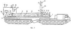
На фиг. 1 представлен общий вид установки для гидравлического испытания труб, на фиг. 2 - привод, на фиг. 3 - гидроприжим, на фиг. 4 - узел заглушки с трубой, на фиг. 5 - схема работы установки в варианте базирования на платформе двухзвенного транспортера ДТ-30. In FIG. 1 is a perspective view of an apparatus for hydraulic testing of pipes; FIG. 2 - drive, in FIG. 3 - hydraulic clamp, in FIG. 4 - a plug assembly with a pipe, in FIG. 5 is a diagram of the operation of the installation in a variant based on the platform of a two-link conveyor DT-30.
Установка содержит раму 1 (фиг. 1), емкость 2, снабженную опорами-днищами 3, 4 с упорами 5, 6; направляющий лоток 7 для укладки труб 8 в емкость 2; грузоподъемный механизм 9, привод 10. The installation contains a frame 1 (Fig. 1), a
Емкость 2 снабжена: прямоугольным вырезом 11; ложементами 12 со сменными накладками 13; гидравлическими прижимами 14 со сменными накладками 15, выполненными плавающими по дуге 16 (фиг. 3) и приводящимися в действие гидроцилиндрами 17.
В емкости 2 расположены: неподвижная заглушка 18, установленная в отверстие 19 опоры 3 с фиксатором 20; подвижная заглушка 21, установленная в отверстие 22 с фиксатором 23 в центре прижимной плиты 24, которая подвижна на роликоопоре 25 и соединена с приводом 10 при помощи трех винтовых пар 25 (фиг. 2) с шаровыми прижимами 27, работающих синхронно. In the
В корпусе заглушек неподвижной 18 и подвижной 21 (фиг. 4) установлены направляющая гильза 28 с конусной расточкой, уплотнительное кольцо 29, уплотнительная манжета 30 с защитным кольцом 31, гайка 32. A guide sleeve 28 with a conical bore, an o-
Гидравлическая система включает (фиг. 5) коллектор 33, соединенный с неподвижной заглушкой 18, пресс 34 для создания давления, воздушный колпак 35, соединенный с подвижной заглушкой 21, контрольные манометры 36, 37, обратный, предохранительный и редукционый клапаны 38, 39, 40, запорную арматуру 41, 42, 43. The hydraulic system includes (Fig. 5) a
Установка работает следующим образом. Installation works as follows.
Трубу 8, подлежащую испытанию, грузоподъемным механизмом 9 по направляющему лотку 7 наклонно опускают в заполненную водой емкость 2, кладут на ложементы 12 с накладками 13 на максимально близком расстоянии от неподвижной заглушки 18, причем сменные накладки 13, 15 и заглушки 18 и 21 должны соответствовать наружному диаметру испытуемой трубы 8. Труба 8 при опускании в емкость 2 через открытые концы заполняется водой. Включают привод 10, соединенный с прижимной плитой 24 подвижной заглушки 21, установленной в отверстие 22, и начинают перемещать подвижную заглушку 21 к концу испытуемой трубы до упора. При этом труба 8 заходит в заглушки 18 и 21. Линия воздушного колпака 35 должна быть открыта. При достижении заданного усилия привод 10 отключают. При помощи гидравлических прижимов 14 с накладками 15 дополнительно фиксируют положение трубы по длине в емкости 2. Приводят в действие гидравлическую систему испытаний. Пресс 34 через обратный клапан 38 соединен с емкостью 2 (фиг. 5) и с заглушкой 18. Запорная арматура 41 на воздушном колпаке 35 подвижной заглушки должна быть открыта. Начинают прессом 34 дополнять трубу 8 водой до появления последней в колпаке 35. Пресс останавливают, запорную раму 41 закрывают, устанавливают при помощи редукционного клапана 40 заданное давление испытания. Прессуют и выдерживают под испытательным давлением трубу установленное время. Снижение давления контролируют двумя манометрами 36 и 37. После окончания испытаний открывают арматуру 42 на линии сброса давления. Для облегчения вывода трубы 8 из заглушек 18, 21 стропят трубу к подвижной плите 24 за ушки или при помощи хомута, надетого вблизи подвижной заглушки. The
При снижении давления отводят гидравлические прижимы 14 в исходное положение и, включив реверсивный механизм привода 10 прижимной плиты 24, освобождают трубу сначала от неподвижной заглушки 18, затем, сняв строповку, освобождают подвижную заглушку 21 из трубы. Трубу 8 во время испытаний не освобождают от захватов грузоподъемных механизмов, при наклоне для слива воды трубу вытаскивают из емкости и складируют, а установка готова к следующим испытаниям. With a decrease in pressure,
Предложенная установка для гидравлических испытаний труб найдет применение в нефтяной, газовой, перерабатывающей и других отраслях промышленности, в коммунальном хозяйстве и там, где есть необходимость в демонтаже и монтаже трубопроводов и их испытаний. The proposed installation for hydraulic pipe testing will find application in the oil, gas, processing and other industries, in utilities and where there is a need for dismantling and installation of pipelines and their tests.
Применение предложенного изобретения позволит снизить длительность и трудоемкость гидравлических испытаний труб различных диаметров, повысить надежность герметизации и обеспечить высокую эффективность обнаружения дефектов, повысить тем самым надежность в целом эксплуатируемого трубопровода. The application of the proposed invention will reduce the duration and complexity of hydraulic testing of pipes of various diameters, increase the reliability of sealing and ensure high efficiency of detection of defects, thereby increasing the reliability of the entire pipeline.
Claims (6)
Translated fromRussianPriority Applications (1)
| Application Number | Priority Date | Filing Date | Title |
|---|---|---|---|
| RU98105348ARU2150683C1 (en) | 1998-03-23 | 1998-03-23 | Pipe hydraulic test set |
Applications Claiming Priority (1)
| Application Number | Priority Date | Filing Date | Title |
|---|---|---|---|
| RU98105348ARU2150683C1 (en) | 1998-03-23 | 1998-03-23 | Pipe hydraulic test set |
Publications (2)
| Publication Number | Publication Date |
|---|---|
| RU98105348A RU98105348A (en) | 2000-01-10 |
| RU2150683C1true RU2150683C1 (en) | 2000-06-10 |
Family
ID=20203783
Family Applications (1)
| Application Number | Title | Priority Date | Filing Date |
|---|---|---|---|
| RU98105348ARU2150683C1 (en) | 1998-03-23 | 1998-03-23 | Pipe hydraulic test set |
Country Status (1)
| Country | Link |
|---|---|
| RU (1) | RU2150683C1 (en) |
Cited By (15)
| Publication number | Priority date | Publication date | Assignee | Title |
|---|---|---|---|---|
| RU2182700C1 (en)* | 2001-02-28 | 2002-05-20 | Федеральное государственное унитарное предприятие "Воронежский механический завод" | Pipe leakage tester |
| RU2195639C2 (en)* | 2001-02-12 | 2002-12-27 | Самарский государственный аэрокосмический университет им. акад. С.П.Королева | Method of hydraulic tests of rolled joints for tightness |
| RU2195638C2 (en)* | 2001-02-12 | 2002-12-27 | Самарский государственный аэрокосмический университет им. акад. С.П.Королева | Method of hydraulic tests of rolled joints for tightness |
| RU2195640C2 (en)* | 2001-02-19 | 2002-12-27 | Самарский государственный аэрокосмический университет им. акад. С.П.Королева | Method of hydraulic tests of rolled joints for tightness |
| RU2215231C2 (en)* | 2001-11-26 | 2003-10-27 | Закрытое акционерное общество НПП "Композит-нефть" | Device for testing combined pipe |
| RU2247957C2 (en)* | 2002-11-27 | 2005-03-10 | Хасанов Ильмер Юсупович | Device for testing pipes |
| RU2267099C1 (en)* | 2004-03-26 | 2005-12-27 | Белоусов Владимир Петрович | System for hydraulic testing |
| RU2267098C1 (en)* | 2004-03-26 | 2005-12-27 | Носаль Василий Иванович | Method of assembling hydraulic system |
| RU2267106C1 (en)* | 2004-03-26 | 2005-12-27 | Даниленко Алексей Викторович | Bench for hydraulic testing of bent pipes |
| RU2267104C1 (en)* | 2004-03-26 | 2005-12-27 | Белоусов Владимир Петрович | Clamping device for connecting pipes to hydraulic system |
| RU2267105C1 (en)* | 2004-03-26 | 2005-12-27 | Белоусов Владимир Петрович | Hydraulic system for testing pipes |
| RU2278364C2 (en)* | 2004-03-26 | 2006-06-20 | Николай Павлович Селиванов | Clamping arrangement |
| RU2278363C2 (en)* | 2004-03-26 | 2006-06-20 | Николай Павлович Селиванов | Clamping arrangement |
| RU2300047C1 (en)* | 2005-11-01 | 2007-05-27 | Ильмер Юсупович Хасанов | Arrangement for testing pipes |
| CN110361267A (en)* | 2019-08-13 | 2019-10-22 | 安徽恒生科技发展集团有限公司 | A kind of pipeline patching device applied voltage test equipment and test method |
- 1998
- 1998-03-23RURU98105348Apatent/RU2150683C1/ennot_activeIP Right Cessation
Cited By (15)
| Publication number | Priority date | Publication date | Assignee | Title |
|---|---|---|---|---|
| RU2195639C2 (en)* | 2001-02-12 | 2002-12-27 | Самарский государственный аэрокосмический университет им. акад. С.П.Королева | Method of hydraulic tests of rolled joints for tightness |
| RU2195638C2 (en)* | 2001-02-12 | 2002-12-27 | Самарский государственный аэрокосмический университет им. акад. С.П.Королева | Method of hydraulic tests of rolled joints for tightness |
| RU2195640C2 (en)* | 2001-02-19 | 2002-12-27 | Самарский государственный аэрокосмический университет им. акад. С.П.Королева | Method of hydraulic tests of rolled joints for tightness |
| RU2182700C1 (en)* | 2001-02-28 | 2002-05-20 | Федеральное государственное унитарное предприятие "Воронежский механический завод" | Pipe leakage tester |
| RU2215231C2 (en)* | 2001-11-26 | 2003-10-27 | Закрытое акционерное общество НПП "Композит-нефть" | Device for testing combined pipe |
| RU2247957C2 (en)* | 2002-11-27 | 2005-03-10 | Хасанов Ильмер Юсупович | Device for testing pipes |
| RU2267099C1 (en)* | 2004-03-26 | 2005-12-27 | Белоусов Владимир Петрович | System for hydraulic testing |
| RU2267098C1 (en)* | 2004-03-26 | 2005-12-27 | Носаль Василий Иванович | Method of assembling hydraulic system |
| RU2267106C1 (en)* | 2004-03-26 | 2005-12-27 | Даниленко Алексей Викторович | Bench for hydraulic testing of bent pipes |
| RU2267104C1 (en)* | 2004-03-26 | 2005-12-27 | Белоусов Владимир Петрович | Clamping device for connecting pipes to hydraulic system |
| RU2267105C1 (en)* | 2004-03-26 | 2005-12-27 | Белоусов Владимир Петрович | Hydraulic system for testing pipes |
| RU2278364C2 (en)* | 2004-03-26 | 2006-06-20 | Николай Павлович Селиванов | Clamping arrangement |
| RU2278363C2 (en)* | 2004-03-26 | 2006-06-20 | Николай Павлович Селиванов | Clamping arrangement |
| RU2300047C1 (en)* | 2005-11-01 | 2007-05-27 | Ильмер Юсупович Хасанов | Arrangement for testing pipes |
| CN110361267A (en)* | 2019-08-13 | 2019-10-22 | 安徽恒生科技发展集团有限公司 | A kind of pipeline patching device applied voltage test equipment and test method |
Similar Documents
| Publication | Publication Date | Title |
|---|---|---|
| RU2150683C1 (en) | Pipe hydraulic test set | |
| KR101753508B1 (en) | Pipe-sealing device for isolating a tank, a pipe or a set of tanks and pipes | |
| RU98105348A (en) | INSTALLATION FOR HYDRAULIC PIPE TESTS | |
| CA1141194A (en) | Clamping apparatus | |
| NO318490B1 (en) | Procedure and installation for laying a pipeline on the seabed | |
| FI80793B (en) | ANORDNING FOER LAECKAGEDETEKTERING. | |
| JP2010500534A (en) | Apparatus and method for separating or testing pipe ends using axial reinforcement | |
| RU2182700C1 (en) | Pipe leakage tester | |
| DK169204B1 (en) | Device for centering and clamping of pipe elements to be welded together | |
| JP3636919B2 (en) | Valve repair jig and method | |
| US4411152A (en) | Method and apparatus for testing pipes | |
| CN1938574A (en) | Apparatus for testing lengths of pipe | |
| US5679886A (en) | Test head assembly for and method of testing heat exchanger components | |
| CN109781606B (en) | A core holder for in-situ seepage CT scanning | |
| RU2247957C2 (en) | Device for testing pipes | |
| JP4059197B2 (en) | Pneumatic material testing machine | |
| RU2833488C1 (en) | Test bench for static and cyclic tests of ring-shaped pipe samples | |
| CN209819031U (en) | Pipe clamping tool for sealing pipeline of pressure instrument | |
| RU2327129C9 (en) | Method for pipes testing | |
| RU2097725C1 (en) | Bed for hydraulic test of pipes | |
| RU2184946C1 (en) | Gear testing pipes for leakage | |
| JP3111193B2 (en) | Inspection equipment | |
| CN109442134A (en) | Clamp Method and kit for for instrument piping with pressure sealing | |
| RU2267105C1 (en) | Hydraulic system for testing pipes | |
| CN212254511U (en) | Pipeline detection equipment |
Legal Events
| Date | Code | Title | Description |
|---|---|---|---|
| MM4A | The patent is invalid due to non-payment of fees | Effective date:20130324 |