RU2148789C1 - Device for measuring length - Google Patents
Device for measuring lengthDownload PDFInfo
- Publication number
- RU2148789C1 RU2148789C1RU98113128ARU98113128ARU2148789C1RU 2148789 C1RU2148789 C1RU 2148789C1RU 98113128 ARU98113128 ARU 98113128ARU 98113128 ARU98113128 ARU 98113128ARU 2148789 C1RU2148789 C1RU 2148789C1
- Authority
- RU
- Russia
- Prior art keywords
- input
- output
- unit
- length
- trigger
- Prior art date
Links
- 238000012545processingMethods0.000claimsabstractdescription32
- 238000005259measurementMethods0.000abstractdescription25
- 230000035945sensitivityEffects0.000abstractdescription5
- 238000004519manufacturing processMethods0.000abstractdescription2
- 230000003247decreasing effectEffects0.000abstract1
- 230000000694effectsEffects0.000abstract1
- 238000005272metallurgyMethods0.000abstract1
- 239000000126substanceSubstances0.000abstract1
- 238000000034methodMethods0.000description15
- 238000000354decomposition reactionMethods0.000description14
- 230000008569processEffects0.000description12
- 230000005855radiationEffects0.000description11
- 238000005286illuminationMethods0.000description6
- 238000004364calculation methodMethods0.000description5
- 229910000831SteelInorganic materials0.000description4
- 230000015572biosynthetic processEffects0.000description4
- 230000008859changeEffects0.000description4
- 230000014509gene expressionEffects0.000description4
- 238000012552reviewMethods0.000description4
- 238000005096rolling processMethods0.000description4
- 239000010959steelSubstances0.000description4
- 238000001514detection methodMethods0.000description3
- 238000009434installationMethods0.000description3
- 230000003595spectral effectEffects0.000description3
- 238000005265energy consumptionMethods0.000description2
- 230000008520organizationEffects0.000description2
- 238000002834transmittanceMethods0.000description2
- 238000004458analytical methodMethods0.000description1
- 230000002146bilateral effectEffects0.000description1
- 230000005540biological transmissionEffects0.000description1
- 230000001364causal effectEffects0.000description1
- 238000010276constructionMethods0.000description1
- 238000005520cutting processMethods0.000description1
- 238000010586diagramMethods0.000description1
- 230000006870functionEffects0.000description1
- 230000007274generation of a signal involved in cell-cell signalingEffects0.000description1
- 238000010438heat treatmentMethods0.000description1
- 230000006872improvementEffects0.000description1
- 238000000691measurement methodMethods0.000description1
- 239000002184metalSubstances0.000description1
- 239000000203mixtureSubstances0.000description1
- 238000010606normalizationMethods0.000description1
- 238000002360preparation methodMethods0.000description1
- 230000002035prolonged effectEffects0.000description1
- 230000009467reductionEffects0.000description1
- 238000010845search algorithmMethods0.000description1
- 230000011664signalingEffects0.000description1
- 230000001960triggered effectEffects0.000description1
Images


Landscapes
- Length Measuring Devices By Optical Means (AREA)
Abstract
Description
Translated fromRussianИзобретение относится к контрольно-измерительной технике и может быть использовано для измерения длины трубных заготовок в прокатно-металлургическом производстве. The invention relates to a measurement technique and can be used to measure the length of pipe billets in rolling and metallurgical production.
Известные устройства измерения длины движущегося проката, как правило, содержат расположенные вдоль направления движения проката фотодатчики целых значений меры длины, выходы которых через усилители соединены с блоками формирования импульсов переднего края проката, штриховой трафарет долей меры длины, расположенный между нулевым и первым фотодатчиками первых значений меры длины и мишенью передающей трубки телевизионной камеры, вход которой соединен с блоком разверток, а выход - с блоком нормирования амплитуды видеосигнала и входом видеоконтрольного блока, счетчик целых значений меры длины и генератор синхроимпульсов, селектор импульсов целых значений меры длины, первый вход которого через сумматор импульсов переднего края проката соединен с выходами блоков формирования импульсов переднего края проката, второй вход - с выходом усилителя нулевого фотодатчика целых значений меры длины, а выход - со входом счетчика целых значений меры длины, формирователь импульса запуска счета дробных значений меры длины, первый вход которого подключен ко входу усилителя нулевого фотодатчика целых значений меры длины, а второй вход - к выходу схемы совпадения, первый вход которой соединен со вторым выходом сумматора импульсов переднего края проката, а второй вход - с выходом усилителя первого фотодатчика целых значений меры длины, блок формирования импульсов сброса, вход которого соединен с выходом нулевого блока формирования импульса переднего края проката, а выход - со вторыми входами счетчика целых значений меры длины и счетчика дробных значений меры длины, селектор видеосигнала строки, первый вход которого соединен с выходом блока нормирования амплитуды видеосигнала, а второй вход - с выходом блока формирования селекторного импульса строки, второй выход которого соединен с входом видеоконтрольного блока, селектор видеосигнала поля, первый вход которого соединен с выходом селектора видеосигнала строки, второй вход - с выходом блока формирования селекторного импульса поля, а выход - с входом счетчика дробных значений меры длины, второй вход блока формирования селекторного импульса первого поля соединен с выходом формирователя импульсов запуска счета дробных значений меры длины, при этом входы управления формирователя селекторного импульса строки, селекторного импульса поля, видеоконтрольного блока и блока разверток соединены с выходом генератора синхроимпульсов. Known devices for measuring the length of a rolling car typically contain photosensors of integer measures of length located along the direction of movement of the car, the outputs of which through amplifiers are connected to pulse forming units of the front edge of the car, a dashed stencil of fractions of a measure of length, located between the zero and first photosensors of the first measures the length and target of the transmitting tube of the television camera, the input of which is connected to the scan unit, and the output to the unit for normalizing the amplitude of the video signal and the input to ideocontrol unit, integer meter of measure of length and a clock generator, pulse selector of integer values of measure of length, the first input of which is connected to the outputs of the pulse generating units of the front edge of the rental through the pulse adder of the front edge of the rental, the second input is the output of the amplifier of the zero photosensor of integer values of the measure of length , and the output is with the input of the counter of integer values of a measure of length, the shaper of the start pulse counting fractional values of a measure of length, the first input of which is connected to the input of an amplifier of zero of a sensor of integer values of a measure of length, and the second input to the output of the coincidence circuit, the first input of which is connected to the second output of the adder of pulses of the front edge of the rental, and the second input to the output of the amplifier of the first photosensor of integer values of a measure of length, a reset pulse generation unit, the input of which is connected with the output of the zero block of the pulse formation of the front edge of the rental, and the output with the second inputs of the counter of integer values of the measure of length and the counter of fractional values of the measure of length, the video signal selector line, the first input of which is connected nen with the output of the unit for normalizing the amplitude of the video signal, and the second input with the output of the unit for forming the selector pulse of the line, the second output of which is connected to the input of the video control unit, the selector of the video signal of the field, the first input of which is connected to the output of the selector of the video signal of the line, the second input is with the output of the forming unit field selector pulse, and the output with the input of the counter of fractional values of a measure of length, the second input of the selector pulse generation unit of the first field is connected to the output of the trigger pulse shaper counting fractional values of a measure of length, while the control inputs of a line selector pulse generator, field selector pulse, a video control unit and a scan unit are connected to the output of the clock generator.
Работают такие устройства следующим образом. В момент появления переднего края измеряемого проката в зоне нулевого фотодатчика нулевой каскад формирования импульса переднего края проката выдает соответствующий сигнал на блок формирования импульса сброса, в результате чего счетчики целых значений и дробных значений меры длины устанавливаются в исходные состояния. Проходя мимо последующих фотодатчиков, передний край проката будет вызывать появление соответствующих сигналов на выходах каскадов формирования импульсов. Эти импульсы через сумматор импульсов переднего края проката поступают на входы селектора импульсов целых значений меры длины и элемент совпадения. Селектор импульсов целых значений меры длины, управляемый сигналом нулевого фотодатчика с выхода усилителя, пропускает на счетчик целых значений меры длины сигналы всех фотодатчиков до тех пор, пока измеряемое изделие находится в зоне нулевого фотодатчика. В момент выхода заднего края проката из зоны нулевого фотодатчика селектор импульсов целых значений меры длины закроется, и на цифровом индикаторе счетчика целых значений меры длины зафиксируется соответствующее значение полных метров длины проката. В момент прохождения переднего края проката мимо следующего очередного фотодатчика измеряется остаточная длина задней части проката. Измерение остаточной части проката осуществляется телевизионной частью устройства, причем импульс запуска счета долей меры длины вырабатывается формирователем импульса запуска счета дробных значений меры длины, который заперт все время, пока измеряемое изделие перекрывает зону нулевого фотодатчика, сигналом с выхода усилителя и пропускает на выход из числа поступающих на его вход с элемента совпадений только импульс очередного фотодатчика. Импульс запуска счета дробных значений меры длины с выхода формирователя поступает на блок формирования селекторного импульса поля, вход кадровых синхроимпульсов которого закрыт до прихода импульса запуска, а после прихода последнего открывается, в результате чего два последующих кадровых импульса формируют селекторный интервал длительностью в одно поле, отпирая селектор видеосигнала на время одного поля развертки, непосредственно следующего за моментом появления переднего края проката в зоне следующего после окончания счета целых значений меры длины очередного фотодатчика. В результате этого через селектор видеосигнала поля на счетчик дробных значений меры длины поступают предварительно сформированные блоком нормирования амплитуды видеосигнала и выделенные селектором видеосигнала строки счетные импульсы, число которых соответствует количеству попадающих в данный момент в поле зрения передающей камеры штрихов квантующего трафарета долей меры длины. Блок формирования селекторного импульса строки настраивается таким образом, чтобы выделяемая строка растра совпадала с осевой линией движения проката. Правильность выбора селектируемой строки контролируется визуально с помощью подсвета строки изображения на экране видеоконтрольного блока. Квантующий штриховой трафарет может быть выполнен в виде штриховой решетки или непрозрачной маски с подсвечиваемыми прорезями, расположение которых должно исключать погрешность параллакса края изделия. Трафарет может быть расположен как перед измеряемым изделием (при измерениях, например, горячего светящегося проката), так и позади него по отношению к передающей ТВК. В последнем случае счетчик дробных значений меры длины должен работать в режиме обратного счета, на его цифровых индикаторах импульсом сброса должно устанавливаться число, соответствующее количеству штрихов трафарета, а результат, полученный при измерении, будет соответствовать действительной длине измеряемого изделия, например, при выбранных расстояниях между фотодатчиками целых значений меры длины в 1 м и 100 штрихах квантующего трафарета на цифровых индикаторах будет высвечиваться число полных метров и сантиметров длины изделия. Результаты измерений в цифровом виде со счетчиков целых и дробных значений меры длины могут быть выведены на вычислительные, регистрирующие и исполнительные блоки. Such devices work as follows. At the moment of the appearance of the leading edge of the measured steel in the zone of the zero photosensor, the zero cascade of pulse formation of the leading edge of the rolled wire gives the corresponding signal to the reset pulse generating block, as a result of which the integer and fractional value counters of the length measure are set to the initial states. Passing by the subsequent photosensors, the front edge of the rental will cause the appearance of the corresponding signals at the outputs of the cascades of pulse formation. These pulses through the pulses adder of the front edge of the rental arrive at the inputs of the pulse selector integer values of the measure of length and the coincidence element. The pulse selector of integer values of the measure of length, controlled by the signal of the zero photosensor from the amplifier output, passes the signals of all photosensors to the counter of integer values of the measure of length as long as the measured product is in the zone of the zero photosensor. At the moment the rear edge of the rolled product leaves the zone of the zero photosensor, the pulse selector of integer values of the measure of length will close, and the corresponding value of the full meters of the length of the hire will be recorded on the digital indicator of the meter of integer values of the measure of length. At the moment the front edge of the car passes by the next next photosensor, the residual length of the rear of the car is measured. The measurement of the remaining part of the rental is carried out by the television part of the device, and the pulse to start counting fractions of the length measure is generated by the pulse shaper to start the calculation of fractional values of the length measure, which is locked all the time while the measured product covers the zone of the zero photosensor with a signal from the amplifier output and passes to the output to its input from the coincidence element, only the pulse of the next photosensor. The start pulse of the counting of fractional values of a measure of length from the output of the shaper enters the block for generating a field selector pulse, the input of the frame sync pulses of which is closed before the start pulse arrives, and after the last pulse arrives, as a result of which two subsequent frame pulses form a selector interval of one field duration, unlocking video signal selector for the duration of one scan field immediately following the appearance of the front edge of the rental in the zone of the integer following the end of the count values of the measure of the length of the next photosensor. As a result, through the field video signal selector, the amplitudes of the video signal preliminarily generated by the normalization unit of the video signal and the counting pulses selected by the video signal selector are received through the field video signal selector, the number of which corresponds to the number of fractions of the length measure currently entering the field of view of the transmitting camera. The block for forming the selector pulse of the line is adjusted so that the selected line of the raster coincides with the axial line of movement of the rental. The correctness of the selection of the selected line is visually controlled by highlighting the image line on the screen of the video control unit. The quantized line-art stencil can be made in the form of a line bar or an opaque mask with illuminated slots, the location of which should exclude the parallax error of the product edge. The stencil can be located both in front of the measured product (when measuring, for example, hot luminous steel), and behind it in relation to the transmitting TCE. In the latter case, the counter of fractional values of the measure of length should work in the mode of counting down, on its digital indicators the reset pulse should set the number corresponding to the number of strokes of the stencil, and the result obtained during the measurement will correspond to the actual length of the measured product, for example, at selected distances between with photosensors of integer values of a measure of length of 1 m and 100 strokes of a quantizing stencil, the number of full meters and centimeters of the length of the product will be displayed on digital indicators. The measurement results in digital form from the counters of integer and fractional values of a measure of length can be displayed on the computational, recording and executive units.
Аналогичные по своей сути устройства измерения длины движущихся изделий запатентованы в Японии, ФРГ, Великобритании, Франции, США, СССР (см. а.с. СССР N 429265, МКИ G 01 В, заявл. 29.05.1972, опубл. 25.05.1974, официальный бюллетень "Открытия. Изобретения" N 19). Similar in essence devices for measuring the length of moving products have been patented in Japan, Germany, Great Britain, France, the USA, and the USSR (see AS USSR N 429265, MKI G 01 B, announced May 29, 1972, published May 25, 1974, Official Bulletin of the Discovery. Inventions N 19).
Признаками, общими с признаками заявляемого технического решения, являются фотодатчик, телевизионная камера, индикатор. Signs common with the features of the claimed technical solution are a photosensor, a television camera, an indicator.
Недостатком таких устройств является требование большого количества осветительных приборов для обеспечения эффективной работы датчиков грубого отсчета и различения штриховых масок ТВК. The disadvantage of such devices is the requirement of a large number of lighting devices to ensure the effective operation of coarse sensors and distinguish TVK line masks.
Причины, препятствующие достижению требуемого технического результата, заключаются в следующем. При измерении труб длиной до 12 метров потребуется установка 13 датчиков грубого отсчета. Каждый датчик состоит из излучающего и принимающего узлов, расположенных по обе стороны от трубы. Мощность ламп, включенных в излучающий узел, обычно превышает 100 Вт. Таким образом, суммарная мощность всей системы из датчиков грубого отсчета превышает 1,3 кВт. Аналогично, для успешной работы телевизионной камеры (ТВК) потребуется обеспечение мощной засветки. The reasons that impede the achievement of the required technical result are as follows. When measuring pipes up to 12 meters in length, 13 coarse readout sensors will be required. Each sensor consists of a radiating and receiving nodes located on both sides of the pipe. The power of the lamps included in the emitting unit, usually exceeds 100 watts. Thus, the total power of the whole system of coarse sensors exceeds 1.3 kW. Similarly, for the successful operation of a television camera (TCE), it will be necessary to provide powerful illumination.
Известно устройство для измерения длины труб (а.с. СССР N 1224559, доп. к а.с. N 446731, МКИ4 G 01 В 7/04, заявл. 3749591/24-28, 06.06.1984, опубл. 15.04.1986, официальный бюллетень "Открытия. Изобретения" N 14).A device is known for measuring the length of pipes (USSR AS N 1224559, additional to AS N 446731, MKI4 G 01
Устройство снабжено направляющими, выполненными с двусторонним уклоном, и содержит наклонный стеллаж, подающий рольганг с роликами, снабженный наружными витками, систему базовых фотодатчиков, размещенных на равных расстояниях друг от друга в межроликовых промежутках рольганга, систему фотодатчиков, установленную с выходной (по ходу продольного перемещения трубы) стороны рольганга, и счетно- решающий блок, который в совокупности с системами фотодатчиков для грубого и точного отсчета соответственно образует измерительную часть устройства. На выходной по ходу поперечного движения трубы стороне рольганга в его межроликовых промежутках установлены направляющие, представляющие собой металлические полосы с двусторонним уклоном. Для выравнивания труб по торцу предназначен упор, установленный на стеллаже и являющийся частью его роликового транспортера. Устройство является усовершенствованием известного устройства, описанного в а.с. СССР N 446731, опубл. в официальном бюллетене "Открытия. Изобретения. Промышленные образцы. Товарные знаки" N 38 за 1974 г. МКИ G 01 В 5/02. The device is equipped with guides made with a two-sided slope, and contains an inclined rack supplying a roller table with rollers, equipped with external coils, a system of basic photosensors placed at equal distances from each other in the roller spans of the roller table, a system of photosensors installed from the output (along the longitudinal movement pipes) of the side of the roller table, and a counting-decisive unit, which, together with the photosensor systems for coarse and accurate reading, respectively forms the measuring part of the device Twa. At the outlet along the lateral movement of the pipe, the side of the roller table has rails installed in its inter-roller spaces, which are metal strips with a bilateral slope. To align the pipes at the end, an emphasis is designed, mounted on the rack and which is part of its roller conveyor. The device is an improvement of the known device described in A.S. USSR N 446731, publ. in the official bulletin "Discoveries. Inventions. Industrial Designs. Trademarks"
Признаками аналога, совпадающими с признаками заявляемого технического решения, являются фотодатчик, счетно-решающий блок. Signs of an analogue that coincide with the features of the claimed technical solution are a photosensor, a counting-decisive unit.
Недостатком известного устройства является потребление датчиками значительной мощности в процессе работы. Помимо этого, применение упора предполагает остановку трубы для проведения измерений, что увеличивает время измерения. A disadvantage of the known device is the consumption of significant power sensors during operation. In addition, the use of the stop involves stopping the pipe for measurements, which increases the measurement time.
Причины, препятствующие достижению требуемого технического результата, состоят в следующем. При измерении труб длиной до 12 метров потребуется установка 13 датчиков грубого отсчета. Каждый датчик состоит из излучающего и принимающего узлов, расположенных по обе стороны от трубы. Мощность ламп, включенных в излучающий узел, обычно превышает 100 Вт. Таким образом, суммарная мощность всей системы из датчиков грубого отсчета превышает 1,3 кВт. Аналогично, для успешной работы телевизионной камеры потребуется обеспечение мощной засветки. The reasons that impede the achievement of the required technical result are as follows. When measuring pipes up to 12 meters in length, 13 coarse readout sensors will be required. Each sensor consists of a radiating and receiving nodes located on both sides of the pipe. The power of the lamps included in the emitting unit, usually exceeds 100 watts. Thus, the total power of the whole system of coarse sensors exceeds 1.3 kW. Similarly, for a successful operation of a television camera, it will be necessary to provide powerful illumination.
Из известных технических решений наиболее близким по технической сущности является устройство автоматического контроля длины движущихся изделий (а. с. СССР N 1242709, МКИ 4 G 01 В, заявл. 3844141/24-28, 17.01.1985, опубл. 21.05.1986, официальный бюллетень "Открытия. Изобретения" N 25). Устройство содержит фотодатчик начала изделия, первый фотодатчик конца изделия, расположенный от фотодатчика начала изделия на расстоянии, равном минимально допустимой длине изделия, второй фотодатчик конца изделия, расположенный от фотодатчика начала изделия на расстоянии, равном максимально допустимой длине изделия, первый, второй и третий блоки обработки сигналов, логический блок, два сигнальных входа которого подключены к выходам соответственно первого и второго блоков обработки сигналов, входы которых подключены к выходам соответствующих фотодатчиков. Устройство, кроме того, снабжено выделяющими фотоэлектрическими преобразователями инфракрасного излучения, равномерно расположенными между фотодатчиком начала и вторым фотодатчиком конца изделия, источниками инфракрасного излучения, количество которых равно числу всех фотоэлектрических преобразователей, дополнительными блоками обработки сигналов, число которых соответствует количеству выделяющих фотоэлектрических преобразователей, блоком выдачи разрешения, оперативно-запоминающим блоком, блоком формирования сигнала сброса, блоком световой индикации. Вход блока световой индикации подключен к выходу оперативно-запоминающего блока, первый вход которого подключен к выходу логического блока, второй вход - к выходу блока формирования сигнала сброса, третий сигнальный вход логического блока подключен к выходу третьего блока обработки сигнала, вход которого связан с выходом фотодатчика начала изделия, четвертый вход логического блока подключен к выходу блока выдачи разрешения, входы которого подключены к выходам дополнительных блоков обработки сигналов, входы которых подключены к соответствующим выходам выделяющих фотоэлектрических преобразователей, входы блока формирования сигнала сброса подключены к выходам двух дополнительных блоков обработки сигналов, входы которых подключены к выходам соответствующих фотоэлектрических преобразователей, расположенных примерно на одинаковом расстоянии от датчиков начала и конца изделия. Кроме того, перед фотодатчиком начала и двумя фотодатчиками конца изделия размещены ограничительные шторки, непроницаемые для инфракрасных лучей. Of the known technical solutions, the closest in technical essence is a device for automatically controlling the length of moving products (a.s. USSR N 1242709, MKI 4 G 01 B, decl. 3844141 / 24-28, 01/17/1985, publ. 21.05.1986, official Bulletin "Discoveries. Inventions" N 25). The device comprises a product start photosensor, a first product end photosensor located from the product start photosensor at a distance equal to the minimum allowable product length, a second product end photosensor located from the product start photosensor at a distance equal to the maximum allowable product length, first, second and third blocks signal processing, a logical unit whose two signal inputs are connected to the outputs of the first and second signal processing units, respectively, whose inputs are connected to the outputs, respectively existing photosensors. The device, in addition, is equipped with infrared emitting photoelectric converters, evenly spaced between the start photosensor and the second end photodetector, infrared radiation sources, the number of which is equal to the number of all photoelectric converters, additional signal processing units, the number of which corresponds to the number of emitted photoelectric converters, output unit permissions, RAM, block reset signal generation, b eye light indication. The input of the light indication unit is connected to the output of the RAM, the first input of which is connected to the output of the logic unit, the second input to the output of the reset signal generating unit, the third signal input of the logical unit is connected to the output of the third signal processing unit, the input of which is connected to the output of the photosensor the beginning of the product, the fourth input of the logical unit is connected to the output of the permit issuing unit, the inputs of which are connected to the outputs of additional signal processing units, the inputs of which are connected to the corresponding to the existing outputs of the emitting photovoltaic converters, the inputs of the reset signal generating unit are connected to the outputs of two additional signal processing units, the inputs of which are connected to the outputs of the corresponding photoelectric converters located at approximately the same distance from the sensors of the beginning and end of the product. In addition, in front of the photosensor of the beginning and two photosensors of the end of the product, restrictive curtains are placed that are impermeable to infrared rays.
Признаки прототипа, совпадающие с признаками заявляемого технического решения, следующие: фотодатчик, блок обработки сигналов, оперативно-запоминающий блок, блок световой индикации. Signs of the prototype, coinciding with the features of the proposed technical solution, are as follows: photosensor, signal processing unit, random-access memory, light indication unit.
Недостатками известного устройства являются:
- большая потребляемая датчиками грубого отсчета мощность;
- зависимость обеспечиваемой точности измерений от скорости перемещения изделия;
- необходимость установки большого числа датчиков и соответствующих им блоков обработки сигналов.The disadvantages of the known device are:
- large power consumed by coarse sensors;
- the dependence of the provided measurement accuracy on the speed of movement of the product;
- the need to install a large number of sensors and their corresponding signal processing units.
Причины, препятствующие достижению требуемого технического результата, заключаются в следующем. При измерении труб длиной до 12 метров потребуется установка 13 датчиков грубого отсчета. Каждый датчик состоит из излучающего и принимающего узлов, расположенных по обе стороны от трубы. Мощность ламп, включенных в излучающий узел, обычно превышает 100 Вт. Таким образом, суммарная мощность всей системы из датчиков грубого отсчета превышает 1,3 кВт. Кроме того, в устройстве не предусмотрена возможность измерения остатка измеряемого изделия, длина которого менее шага установки основных и дополнительных датчиков. The reasons that impede the achievement of the required technical result are as follows. When measuring pipes up to 12 meters long, 13 coarse readout sensors will be required. Each sensor consists of a radiating and receiving nodes located on both sides of the pipe. The power of the lamps included in the emitting unit, usually exceeds 100 watts. Thus, the total power of the whole system of coarse sensors exceeds 1.3 kW. In addition, the device does not provide the ability to measure the remainder of the measured product, the length of which is less than the installation step of the primary and secondary sensors.
Таким образом, для минимизации погрешностей измерения требуется интенсивная подсветка вдоль длины трубного проката. Thus, to minimize measurement errors, intensive illumination along the length of the rolled pipe is required.
Задача, на решение которой направлено изобретение, заключается в снижении энергопотребления в процессе измерения длины трубных заготовок на пилигримовом стане и повышении точности измерения длины объекта. The problem to which the invention is directed, is to reduce energy consumption in the process of measuring the length of pipe billets on a pilgrim mill and increasing the accuracy of measuring the length of the object.
Технический результат, достигаемый при осуществлении изобретения, позволяет уменьшить энергопотребление примерно на 1 кВт/ч за счет исключения необходимости установки всех датчиков целых значений меры длины, кроме нулевого датчика, энергопотребление которого ничтожно мало, т.к. нулевой датчик срабатывает от собственного излучения нагретой трубной заготовки, и применения диссектора - телевизионной передающей трубки мгновенного действия, обеспечивающей сверхвысокую чувствительность аппаратуры вплоть до работы в режиме счета отдельных фотонов, что позволяет регистрировать собственное излучение нагретого тела, в результате чего полностью исключается необходимость подсветки трубной заготовки в процессе измерения, а также повысить точность измерения. The technical result achieved by the implementation of the invention allows to reduce power consumption by about 1 kW / h by eliminating the need to install all sensors of integer values of a measure of length, except for a zero sensor, the power consumption of which is negligible, because the zero sensor is triggered by the intrinsic radiation of the heated tube billet, and the use of a dissector - an instantaneous television transmitting tube that provides ultra-high sensitivity of the apparatus up to operating in the counting mode of individual photons, which allows one to register the radiation of a heated body, which completely eliminates the need to illuminate the tube billet in the measurement process, and also improve the accuracy of the measurement.
В прототипе точность измерения в значительной мере определяется точностью установки фотодатчиков и шагом их расположения. В предлагаемом изобретении точность измерения определяется размером апертуры диафрагмы и параметрами блока развертки диссектора. Реализация блока развертки в цифровой форме гарантирует высокую точность измерения длины объекта. In the prototype, the measurement accuracy is largely determined by the accuracy of the installation of the photosensors and the step of their location. In the present invention, the measurement accuracy is determined by the size of the aperture of the diaphragm and the parameters of the scanner unit of the dissector. The implementation of the scanner in digital form guarantees high accuracy in measuring the length of an object.
Технический результат достигается тем, что в устройство измерения длины, содержащее фотодатчик, блок обработки сигналов и оперативно-запоминающий блок (ОЗБ), дополнительно введены телевизионная камера на основе диссектора (ТВК), коммутатор, постоянное запоминающее устройство (ПЗУ), блок поиска (БП), схема совпадений (СС), счетно-решающий блок, два RS-триггера, три элемента И, элемент ИЛИ и индикатор, причем выход фотодатчика объединен с первыми входами первого и третьего элементов И и со вторым входом схемы совпадений; выход телевизионной камеры подключен ко входу блока обработки сигналов, выход которого объединен с S-входом первого RS-триггера, вторым входом первого элемента И и с первым входом схемы совпадений, третий вход которой объединен с выходом первого RS-триггера и вторыми входами второго и третьего элементов И, а выход подключен к S-входу второго RS-триггера и первому входу блока поиска; R-вход второго RS-триггера соединен со вторым выходом блока поиска и вторым входом элемента ИЛИ, выход второго RS-триггера соединен со вторым входом блока поиска и управляющим входом коммутатора, первый адресный вход которого подключен к выходу ПЗУ, а второй адресный вход соединен с первым выходом блока поиска, выход коммутатора объединен с входом ТВК и информационным входом ОЗБ; вход ПЗУ подключен к выходу третьего элемента И; выход первого элемента И соединен с первым входом элемента ИЛИ, выход которого объединен с первым входом второго элемента И и управляющим входом ОЗБ, выход которого подключен к информационному входу счетно-решающего блока, управляющий вход которого объединен с выходом второго элемента И и R-входом первого RS-триггера, выход счетно-решающего блока соединен со входом индикатора. The technical result is achieved by the fact that in the length measuring device containing a photosensor, a signal processing unit and a random access memory (OZB), a television camera based on a dissector (TCE), a switch, a read-only memory (ROM), a search unit (PSU) are additionally introduced ), a coincidence circuit (CC), a counting-decisive block, two RS-flip-flops, three AND elements, an OR element and an indicator, the output of the photosensor being combined with the first inputs of the first and third AND elements and with the second input of the coincidence circuit; the output of the television camera is connected to the input of the signal processing unit, the output of which is combined with the S-input of the first RS-trigger, the second input of the first element And and with the first input of the matching circuit, the third input of which is combined with the output of the first RS-trigger and the second inputs of the second and third elements And, and the output is connected to the S-input of the second RS-trigger and the first input of the search unit; The R-input of the second RS-trigger is connected to the second output of the search unit and the second input of the OR element, the output of the second RS-trigger is connected to the second input of the search unit and the control input of the switch, the first address input of which is connected to the ROM output, and the second address input is connected to the first output of the search unit, the output of the switch is combined with the input of the TCE and the information input of the OZB; the ROM input is connected to the output of the third AND element; the output of the first AND element is connected to the first input of the OR element, the output of which is combined with the first input of the second And element and the control input of the OZB, the output of which is connected to the information input of the computing unit, the control input of which is combined with the output of the second And element and the R-input of the first RS-trigger, the output of the computing unit is connected to the input of the indicator.
Анализ существенных признаков аналогов, прототипа и заявляемого объекта выявил следующие новые существенные признаки для заявляемого объекта:
- построение ТВК на основе диссектора (передающей телевизионной трубки мгновенного действия) позволяет резко повысить чувствительность ТВК вплоть до работы в режиме счета отдельных фотонов, что позволяет для определения местоположения трубной заготовки использовать собственное тепловое излучение заготовки без применения дополнительной подсветки;
- первый элемент И, первый вход которого подключен к выходу фотодатчика, второй вход - к выходу блока обработки сигналов, а выход соединен с первым входом элемента ИЛИ, формирует импульсы при прохождении передним краем объекта отметок 6 или 12 м: если длина плети L превышает 12 м, то на выходе первого элемента И импульсы появляются в моменты пересечения трубной заготовкой Lтр отметок 6 и 12 м на измерительной части пилигримового стана, если длина остатка плети 6 ≤ Lтр < 12 м, то импульс генерируется только в момент достижения передним краем измеряемого объекта отметки 6 м, и, наконец, при 0 ≤ Lтр < 6 м, на выходе второго элемента постоянно действует напряжение логического нуля (импульс не формируется);
- элемент ИЛИ, первый вход которого подключен к выходу первого элемента И, второй вход - к выходу первого RS-триггера, а выход - к управляющему входу ОЗБ; на выходе элемента ИЛИ помимо импульсов с выхода первого элемента И появляются дополнительные сигналы в момент обнаружения переднего края заготовки при поиске;
- второй элемент И, первый вход которого подключен к выходу элемента ИЛИ, второй вход - к выходу первого RS-триггера, а выход - к управляющему входу счетно-решающего блока, формирует напряжение логической "1" по окончании цикла измерения для формирования окончательного результата и перевода системы в исходное состояние; первый RS-триггер, S-вход которого подключен к выходу блока обработки сигналов, R-вход - к выходу второго элемента И, а выход - ко входу ПЗУ, фиксирует факт прохождения передним краем объекта отметки 6 м: в момент прохождения передним концом трубной заготовки отметки 6 м на выходе первого RS-триггера появляется напряжение логической "1", сохраняющееся до окончания измерения; второй RS-триггер, S-вход которого соединен с выходом схемы совпадений, R-вход - с вторым выходом блока поиска, а выход подключен ко второму входу блока поиска, фиксирует режим поиска от момента поступления импульса с выхода схемы совпадений (СС) до прихода сигнала со второго выхода блока поиска об окончании поиска местоположения переднего края заготовки;
- схема совпадений (СС), первый вход которой соединен с выходом блока обработки сигналов, второй вход - с выходом фотодатчика, третий вход - с выходом первого RS-триггера, а выход объединен с S-входом второго RS-триггера и первым входом блока поиска, переводит устройство из режима ожидания в режим поиска переднего края трубной заготовки: в случае прохождения задним концом трубной заготовки (остатка плети) нулевой отметки, контролируемой фотодатчиком, на выходе схемы устанавливается напряжение логической "1"; это напряжение появляется непосредственно в момент прохождения задним краем заготовки нулевой отметки при 6 ≤ L < 12 м или в момент прохождения задним краем объекта отметки 6 м при L < 6 м;
- ПЗУ, в котором хранятся коды, соответствующие сканированию (обзору) диссектором первого (6 м) или последнего (12 м) элементов разложения в строке; причем при появлении на входе ПЗУ напряжения логического "0" на его выходе устанавливается цифровой код, обеспечивающий обзор диссектором отметки 6 м, а при напряжении логической "1" производится контроль отметки 12 м;
- коммутатор, первый и второй адресные входы которого подключены к выходам соответственно ПЗУ и блока поиска, а управляющий вход - к выходу второго RS-триггера, позволяет в зависимости от напряжения на управляющем входе дискретно, а не последовательно анализировать элементы разложения в строке диссектора (мерные отметки между 6 и 12 м): при напряжении логического "0" на управляющем входе коммутатора на вход ТВК поступает код с выхода ПЗУ, соответствующий отметкам 6 или 12 м, а при напряжении логической "1" на выходе коммутатора действует код с выхода блока поиска, соответствующий номеру анализируемого в данный момент элемента разложения строки диссектора;
- блок поиска, первый вход которого соединен с выходом схемы совпадений, второй вход - с выходом второго RS-триггера, первый адресный выход - с R-входом второго RS-триггера и вторым входом элемента ИЛИ, позволяет определять местоположения переднего края трубной заготовки, представляющей собой остаток плети длиной менее 12 м; в момент обнаружения переднего края заготовки на втором выходе блока поиска появляется импульс, обнуляющий второй RS-триггер и переводящий устройство снова в режим ожидания;
- ОЗБ, в котором фиксируется длина отрезка трубной заготовки от 0 до 6 м; в случае превышения заготовкой величины 6 м в ОЗБ записывается сначала код, соответствующий 6 м, а затем код, определяющий длину Lтр - 6, а если L < 6 м, то производится запись кода, соответствующего длине Lтр = L; процесс записи управляется сигналами с выхода элемента ИЛИ;
- счетно-решающий блок (СРБ), в котором определяется путем суммирования кодов с выхода ОЗБ реальная длина трубной заготовки.The analysis of the essential features of analogues, prototype and the claimed object revealed the following new essential features for the claimed object:
- the construction of a TCE on the basis of a dissector (instantaneous transmitting television tube) can sharply increase the sensitivity of a TCE up to operating in the mode of counting individual photons, which allows using the workpiece’s own thermal radiation without additional illumination to determine the location of a tube billet;
- the first element And, the first input of which is connected to the output of the photosensor, the second input - to the output of the signal processing unit, and the output is connected to the first input of the OR element, generates pulses when the front edge of the object passes marks of 6 or 12 m: if the length of the lash L exceeds 12 m, then the output of the first aND gate pulses occur at the instants of crossing tubular preform Ltr marks 6 and 12 m in the measuring part pilger mill, if the
- an OR element, the first input of which is connected to the output of the first AND element, the second input - to the output of the first RS-trigger, and the output - to the control input of the OZB; at the output of the OR element, in addition to the pulses from the output of the first AND element, additional signals appear at the moment of detecting the leading edge of the workpiece during the search;
- the second AND element, the first input of which is connected to the output of the OR element, the second input - to the output of the first RS-trigger, and the output - to the control input of the counting-decisive block, generates a logical "1" voltage at the end of the measurement cycle to form the final result and resetting the system; the first RS-trigger, the S-input of which is connected to the output of the signal processing unit, the R-input - to the output of the second AND element, and the output - to the ROM input, fixes the fact that the front edge of the object passes the 6 m mark: at the moment the front end of the tube passes through mark 6 m at the output of the first RS-trigger appears logical voltage "1", which remains until the end of the measurement; the second RS-trigger, the S-input of which is connected to the output of the match circuit, the R-input is connected to the second output of the search block, and the output is connected to the second input of the search block, fixes the search mode from the moment the pulse arrives from the output of the match circuit (CC) until it arrives a signal from the second output of the search unit about the end of the search for the location of the leading edge of the workpiece;
- a coincidence circuit (CC), the first input of which is connected to the output of the signal processing unit, the second input - with the output of the photosensor, the third input - with the output of the first RS-trigger, and the output is combined with the S-input of the second RS-trigger and the first input of the search block , transfers the device from standby mode to search mode for the front edge of the pipe billet: if the rear end of the pipe billet (lash residue) passes the zero mark controlled by the photosensor, the logic output voltage is set to “1”; this voltage appears immediately at the moment when the rear edge of the workpiece passes the zero mark at 6 ≤ L <12 m or at the moment the rear edge of the object passes the mark of 6 m at L <6 m;
- ROM, which stores codes corresponding to scanning (review) by the dissector of the first (6 m) or last (12 m) decomposition elements in a line; moreover, when a logical “0” voltage appears at the input of the ROM, a digital code is set at its output, which provides a review of the 6 m mark by the dissector, and a 12 m mark is monitored with a logical “1” voltage;
- a switch, the first and second address inputs of which are connected to the outputs of the ROM and the search unit, respectively, and the control input - to the output of the second RS-trigger, allows you to analyze decomposition elements in the dissector line (dimensional marks between 6 and 12 m): at a logic "0" voltage at the control input of the switch, a code from the ROM output corresponding to marks of 6 or 12 m is received at the TVK input, and with a logic "1" voltage, a code with output Yes, the search block corresponding to the number of the element of decomposition of the line of the dissector being analyzed at the moment;
- the search unit, the first input of which is connected to the output of the coincidence circuit, the second input - with the output of the second RS-trigger, the first address output - with the R-input of the second RS-trigger and the second input of the OR element, allows you to determine the location of the front edge of the tube stock representing the rest of the whip less than 12 m long; at the moment of detecting the leading edge of the workpiece, a pulse appears at the second output of the search unit, resetting the second RS-trigger and putting the device back into standby mode;
- OZB, in which the length of the pipe billet segment is fixed from 0 to 6 m; if the workpiece exceeds a value of 6 m, the code corresponding to 6 m is written first in the OZB, and then the code defining the length Ltr - 6, and if L <6 m, then the code corresponding to the length Ltr = L is recorded; the recording process is controlled by signals from the output of the OR element;
- counting-decisive block (SRB), in which the actual length of the pipe billet is determined by summing the codes from the output of the OZB.
Теоретическое доказательство наличия причинно-следственной связи совокупности заявляемых существенных признаков с указанным техническим результатом заключается в следующем. The theoretical evidence for the presence of a causal relationship of the totality of the claimed essential features with the specified technical result is as follows.
В решаемой задаче источником полезного сигнала является тепловое излучение нагретой до T = 800...1000 K поверхности изделия прокатно-металлургического производства. В отличие от абсолютно черного тела (АЧТ) излучение реальных излучателей описывается выражением:
где C1 = 2hc2 = 1,19107•10-16[Bтм2/ср]; C2 = hc/kБ = 1,4388•10-2[м•K],
λ - длина волны принимаемого излучения.In the problem to be solved, the source of the useful signal is the thermal radiation of the surface of a rolling-metallurgical product heated to T = 800 ... 1000 K. Unlike a black body (blackbody), the radiation of real emitters is described by the expression:
where C1 = 2hc2 = 1,19107 • 10-16 [Bm m2 / sr]; C2 = hc / kB = 1.4388 • 10-2 [m • K],
λ is the wavelength of the received radiation.
Поскольку все изображение излучающей поверхности проецируется на Nэл элементов разложения строки диссектора, то линейным размерам элементов a•b соответствуют размеры участка трубы A и B, определяемые выражениями A = L/Nэл, B = b•A/a.Since the entire image of the radiating surface is projected onto the Nel elements of the decomposition of the dissector row, the linear dimensions of the elements a • b correspond to the dimensions of the pipe section A and B, defined by the expressions A = L / Nel , B = b • A / a.
Выходной ток с i-го фотоэлемента (


Eабс - максимальная монохроматическая чувствительность фотоприемника,
Катм - коэффициент пропускания атмосферы,
Кпр.опт - коэффициент пропускания приемной оптики,
εизл(λ,T) - спектральный коэффициент теплового излучения серого тела,
Eотн(λ) - спектральная чувствительность фотоприемника,
ВАЧТ (λ,T) - спектральная плотность энергетической яркости абсолютно черного тела,
а с центра линейки при i = 1
Блок обработки сигналов, как правило, включает усилитель, фильтр нижних частот (ФНЧ) или полосовой фильтр.Output current from the i-th photocell (
Eabs is the maximum monochromatic sensitivity of the photodetector,
Katm - transmittance of the atmosphere,
Topr.opt - transmittance of the receiving optics,
εizl (λ, T) is the spectral coefficient of thermal radiation of the gray body,
Erel (λ) is the spectral sensitivity of the photodetector,
Inblackbody (λ, T) is the spectral density of the energy brightness of a completely black body,
and from the center of the ruler for i = 1
The signal processing unit typically includes an amplifier, a low-pass filter (low-pass filter) or a band-pass filter.
Сигнал на выходе фильтра представляет композицию
ζ(t) = uc(t) + uф(t) + nc(t) + nф(t) + nтемн.т.(t), (2)
в котором индексы "с", "ф" и "темн.т" означают принадлежность детерминированных u(t) и случайных n(t) составляющих напряжения к ансамблям сигнала, фона и темнового тока соответственно. Из формулы (2) видно, что отличительной особенностью шумов диссекторных датчиков является их нестационарность, обусловленная зависимостью мощности шума от интенсивности полезного излучения Ic.The signal at the output of the filter represents the composition
ζ (t) = uc (t) + uf (t) + nc (t) + nf (t) + ndark (t), (2)
in which the indices "c", "f" and "dark.t" mean that the determinate u (t) and random n (t) components of the voltage belong to signal, background, and dark current ensembles, respectively. From formula (2) it can be seen that a distinctive feature of the noise of dissector sensors is their non-stationarity, due to the dependence of the noise power on the intensity of the useful radiation Ic .
При нормальной аппроксимации флуктуационного процесса диссектора алгоритм оптимального обнаружения проекции может быть найден путем анализа логарифма отношения правдоподобия
Λ(ζ) = A1ζ2+B1ζ+C1. (3)
Условием обнаружения проекции объекта на фотокатод является превышение величиной Λ(ζ) некоторого порога, определяемого выбранным критерием обнаружения.With a normal approximation of the fluctuation process of the dissector, the optimal projection detection algorithm can be found by analyzing the logarithm of the likelihood ratio
Λ (ζ) = A1 ζ2 + B1 ζ + C1 . (3)
The condition for detecting the projection of an object onto the photocathode is an excess of Λ (ζ) of a certain threshold determined by the selected detection criterion.
Формула (3) свидетельствует о том, что оптимальный обнаружитель в рассматриваемой диссекторной системе с цифровой разверткой требует нелинейной обработки над процессом с выхода фильтра. Квадратичная обработка является здесь платой за работу диссектора в сугубо нестационарном режиме. Formula (3) indicates that the optimal detector in the considered dissector system with digital scanning requires non-linear processing of the process from the filter output. The quadratic processing is here the payment for the dissector in a purely unsteady mode.
При длительном наблюдении элемента разложения средние статистические характеристики процесса на выходе диссектора достигают своих предельных значений. При этом коэффициент В1 в формуле (3) становится равным нулю. Правило обнаружения сигнала в этих условиях преобразуется к виду
ζ > Uпор. (4)
Для алгоритма (4) величина порога Uпор по критерию Неймана-Пирсона находится по заданной вероятности ложных тревог Pлт
Uпф= mo+σoФ-1(1-Pлт) (5)
где m0 = KфIф - среднее значение (математическое ожидание) принимаемой реализации процесса;
σ
Iф - интенсивность фонового излучения;
Кф - коэффициент передачи фильтра;
Δfэфф - эффективная полоса пропускания.With prolonged observation of the decomposition element, the average statistical characteristics of the process at the output of the dissector reach their limiting values. In this case, the coefficient B1 in the formula (3) becomes equal to zero. The rule for detecting a signal under these conditions is converted to
ζ> Uthen (4)
For algorithm (4), the threshold value Uthen, according to the Neumann-Pearson criterion, is found from the given probability of false alarms Plt
Upf = mo + σo Ф-1 (1-Plt ) (5)
where m0 = Kf If - the average value (mathematical expectation) of the accepted implementation of the process;
σ
If - the intensity of the background radiation;
Tof - the transmission coefficient of the filter;
Δfeff is the effective bandwidth.
функция Ф-1(х) обратная
Уравнение рабочей характеристики обнаружителя, фиксирующего момент перекрытия проекцией переднего края трубной заготовки половины элемента разложения и реализующего алгоритм (4), имеет вид
где q = Ic/Iф;
to= 1,26•τa - момент срабатывания порогового устройства;
τв - постоянная времени ФНЧ.The equation of the operating characteristic of the detector, fixing the moment of overlapping by the projection of the front edge of the tube stock of half of the decomposition element and implementing algorithm (4), has the form
where q = Ic / If ;
to = 1.26 • τa is the moment of operation of the threshold device;
τin - time constant of the low-pass filter.
Выражение (6) показывает, что вероятностные характеристики обнаружителя проекции изображения трубы зависят не только от отношения сигнал/фон q, но и от абсолютных значений последних. Так, например, если при Pл.т.=0,1, q = 1 и принимаемом зарядовом пакете Ict0/е= 14 возможно обеспечение вероятности пропуска сигнала не выше 6,4•10-2, то при Ict0/е = 50 - уже 1,2•10-4.Expression (6) shows that the probabilistic characteristics of the detector of the projection of the image of the pipe depend not only on the signal / background ratio q, but also on the absolute values of the latter. So, for example, if at Pl.t. = 0.1, q = 1 and the accepted charge packet Ic t0 / е = 14, it is possible to ensure the probability of signal skipping not higher than 6.4 • 10-2 , then with Ic t0 / е = 50 it is already 1.2 • 10-4 .
Расчеты показывают, что при реальном нагреве труб до Т=800...1200 К и q= 33 удается обеспечить Pл.т.= 0.1 и Pобн. = 0,99. Это гарантирует ошибку в обнаружении положения переднего края ε = 0,1 размера элемента. Последнее указывает на отсутствие необходимости дополнительного освещения измерительного участка стана и установки дополнительных мерных датчиков.Calculations show that with real heating of the pipes to T = 800 ... 1200 K and q = 33, it is possible to provide PL. = 0.1 and Pobn. = 0.99. This guarantees an error in detecting the position of the leading edge ε = 0.1 of the element size. The latter indicates the absence of the need for additional illumination of the measuring section of the mill and the installation of additional dimensional sensors.
Последнее и гарантирует достижение поставленной цели. The latter guarantees the achievement of the goal.
Сущность предлагаемого технического решения поясняется чертежами. The essence of the proposed technical solution is illustrated by drawings.
На фиг.1 представлена структурная схема устройства измерения длины. Вариант реализации блока поиска показан на фиг. 2, а схемы совпадений - на фиг. 3. Организацию измерения длины трубных заготовок иллюстрирует фиг. 4. Алгоритм работы всего устройства иллюстрирует фиг. 5, а временные эпюры - фиг. 6. Figure 1 presents a structural diagram of a device for measuring length. An embodiment of the search unit is shown in FIG. 2, and match patterns are shown in FIG. 3. The organization of measuring the length of the tube blanks is illustrated in FIG. 4. The operation algorithm of the entire device is illustrated in FIG. 5, and time plots of FIG. 6.
Таблицы состояний устройства измерения длины показаны на фиг. 7 при длине плети более 12 м, на фиг. 8 при длине остатка плети 6 м ≤ L < 12 м и на фиг. 9 при L < 6 м. Пример работы блока поиска иллюстрируют фиг. 10 и фиг. 11. The state tables of the length measuring device are shown in FIG. 7 with a whip length of more than 12 m, in FIG. 8 with the length of the lash remaining 6 m ≤ L <12 m and in FIG. 9 at L <6 m. An example of the operation of the search unit is illustrated in FIG. 10 and FIG. eleven.
Устройство содержит (см. фиг.1) элемент ИЛИ 1, первый 2 и второй 3 элементы И, фотодатчик 4, первый RS-триггер 5, третий элемент И 6, блок обработки сигналов 7, ПЗУ 8, схему совпадений 9, коммутатор 10, ТВК 11, второй RS-триггер 12, блок поиска 13, ОЗБ 14, счетно-решающий блок 15 и индикатор 16. The device contains (see Fig. 1) an OR
Элемент ИЛИ 1 первым входом подключен к выходу первого элемента И 2, а выходом соединен с первым входом второго элемента И 3. Фотодатчик 4 выходом подключен к первому входу первого элемента И 2. Первый RS-триггер 5 S-входом соединен со вторым входом первого элемента И 2, R-входом подключен к выходу второго элемента И 3, а выходом подключен к второму входу второго элемента И 3. Первый вход третьего элемента И 6 соединен с первым входом первого элемента И 2 и подключен к выходу фотодатчика 4, второй вход объединен со вторым входом второго элемента И 3 и подключен к выходу первого RS-триггера 5. Выход блока обработки сигналов 7 подключен ко второму входу первого элемента И 2 и S-входу первого RS-триггера 5. ПЗУ 8 входом подключен к выходу третьего элемента И 6. Схема совпадений 9 первым входом объединена со вторым входом первого элемента И 2, S-входом первого RS-триггера 5 и подключена к выходу блока обработки сигналов 7, вторым входом объединена с первыми входами первого 2 и третьего 6 элементов И и подключена к выходу фотодатчика 4. Коммутатор 10 первым адресным входом подключен к выходу ПЗУ, а выходом подключен к входу ТВК 11. ТВК 11 входом подключена к выходу коммутатора 10, а выходом подключена к входу блока обработки сигналов 7. Второй RS-триггер 12 R-входом объединен со вторым входом элемента ИЛИ 1 и подключен ко второму выходу блока поиска 13, S-входом объединен с первым входом блока поиска 13 и подключен к выходу схемы совпадений 9, а выходом подключен к управляющему входу коммутатора 10 и второму входу блока поиска 13. Первый выход блока поиска 13 подключен ко второму адресному входу коммутатора 10. ОЗБ 14 информационным входом объединен со входом ТВК 11 и подключен к выходу коммутатора 10, управляющим входом объединен с первым входом второго элемента И 3 и подключен к выходу элемента ИЛИ 1, а выходом подключен к информационному входу счетно-решающего блока 15. Счетно-решающий блок 15 управляющим входом объединен с R-входом первого RS-триггера 5 и подключен к выходу второго элемента И 3, а выходом подключен к индикатору 16. The OR
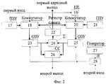
Блок поиска содержит (см. фиг.2) первое ПЗУ 17, первый коммутатор 18, элемент НЕ 17, второй коммутатор 20, второе ПЗУ 21, регистр сдвига 22, первое ОЗУ 23, сумматор 24, ОЗУ 25, схему совпадений 26, генератор 27 и элемент И 28. The search unit contains (see FIG. 2) the
Первое ПЗУ 17 выходом подключено к первому входу первого коммутатора 18. Элемент НЕ 19 входом объединен с управляющим входом первого коммутатора 18 и подключен к первому входу блока поиска 13, а выходом подключен к управляющему входу второго коммутатора 20. Второй коммутатор 20 первым входом подключен к выходу второго ПЗУ 21, вторым входом объединен со вторым входом первого коммутатора 19, первым адресным выходом блока поиска 13 и подключен к выходу регистра сдвига 22. Первое ОЗУ 23 входом данных подключено к выходу первого коммутатора 18, а выходом соединено с первым входом сумматора 24. Сумматор 24 вторым входом подключен к выходу второго ОЗУ 25, а выходом соединен со входом регистра сдвига 22. Второе ОЗУ 25 входом данных подключено к выходу второго коммутатора 20, а выходом соединено с объединенными вторыми входами сумматора 24 и схемы совпадений 26. Схема совпадений 26 первым входом подключена к выходу первого ОЗУ 23, а выходом соединена со вторым выходом блока поиска 13. Генератор 27 выходом подключен к первому входу элемента И 28. Элемент И 28 вторым входом подключен ко второму входу блока поиска 13, а выход соединен с управляющими входами первого 23 и второго 25 ОЗУ. The
Схема совпадений 9 содержит (см. фиг. 3) первый и второй элементы НЕ 29 и 30 и элемент И 31. The
Первый 29 и второй 30 элементы НЕ входами подключены соответственно к первому и второму входам схемы совпадений 9, а выходами - к первому и второму входам элемента И 31. Элемент И 31 третьим входом соединен с третьим входом схемы совпадений 9 непосредственно, а выходом подключен к выходу схемы совпадений 9. The first 29 and second 30 elements are NOT inputs connected respectively to the first and second inputs of the
На фиг. 4 представлена организация измерения длины трубных заготовок в технологической линии прокатного стана. Труба движется вдоль измерительной части стана со скоростью
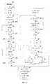
На фиг. 5 блоки 32 и 33 описывают начальные установки, блоки 34-35 - ожидание момента появления нагретого объекта на отметке 6 м, блоки 36-38 - ожидание момента появления нагретого объекта на отметке 6 м, блоки 40-42 - ожидание момента появления нагретого объекта на отметке 12 м, блоки 43-47 - работу устройства при подготовке к измерению остатка менее 6 м, блоки 48-53 поясняют процесс поиска границы остатка трубы, а блоки 54-56 отображают вычисление и вывод результата. In FIG. 5
На фиг. 6 показаны напряжения на выходах фотодатчика 4 (а), третьего элемента И 6 (б), блока обработки сигналов 7 (в), первого RS-триггера 5 (г), втором выходе блока поиска 13 (д), выходе второго RS-триггера 12 (е), схемы совпадений 9 (ж), первого элемента И 2 (з), элемента ИЛИ 1 (и), второго элемента И 3 (к), а также положение переднего края заготовки (л). In FIG. 6 shows the voltage at the outputs of the photosensor 4 (a), the third element And 6 (b), the signal processing unit 7 (c), the first RS-trigger 5 (d), the second output of the search unit 13 (d), the output of the second RS-trigger 12 (e), coincidence patterns 9 (g), the first element And 2 (h), the element OR 1 (s), the second element And 3 (k), as well as the position of the front edge of the workpiece (l).
Рассмотрим пример использования изобретения в линии пилигримового прокатного стана на участке горячей резки. Камера располагается на высоте H от стана, обеспечивающей проекцию на фотокатод диссектора участка измерительной части стана между мерными отметками 6 и 12 м (см. фиг. 4). Применение диссектора позволяет организовать дискретную развертку в пределах строки, располагающейся вдоль оси движения трубной заготовки. Строка сканируется дискретно элементом разложения, размеры которого определяют точность измерения. Consider an example of the use of the invention in a line of a pilgrim rolling mill at a hot cutting site. The camera is located at a height H from the mill, providing a projection onto the photocathode of the dissector of the measuring section of the mill between the measuring marks of 6 and 12 m (see Fig. 4). The use of a dissector allows you to organize a discrete scan within a line located along the axis of movement of the pipe billet. The string is scanned discretely by the decomposition element, the dimensions of which determine the measurement accuracy.
Нагретая труба перемещается с некоторой скоростью
В этом случае устройство работает следующим образом. In this case, the device operates as follows.
Основным режимом работы устройства является режим ожидания, при котором система "ожидает" прохождения отрезка объекта определенной длины мимо пилы ударного реза. The main mode of operation of the device is the standby mode, in which the system "expects" the passage of a segment of an object of a certain length past the impact cut saw.
В исходном состоянии (фиг. 5, блок 32) объект отсутствует в поле зрения ТВК 11 и фотодатчика 4. На выходах фотодатчика 4 и блока обработки сигналов 7 ТВК 11 присутствуют уровни логического "0" (фиг. 5, блок 33). Этими сигналами заперты первый 2 и третий 6 элементы И. Первый RS-триггер 5 сброшен в состояние, при котором на его выходе присутствует уровень логического "0", который в свою очередь запирает схему совпадений 9, входящую в состав блока включения режима поиска (фиг.7). In the initial state (Fig. 5, block 32), the object is not in the field of view of the
В момент появления переднего края измеряемого объекта в поле зрения фотодатчика 4 на выходе последнего формируется сигнал (фиг. 5, блок 35), соответствующий уровню логической "1", который открывает первый 2 и третий 6 элементы И. На выходе первого RS-триггера 5 сохраняется уровень логического "0" (см. фиг. 6,г), что соответствует обзору ТВК отметки 6 м (фиг. 5, блок 36). At the moment the leading edge of the measured object appears in the field of view of the
При появлении переднего края нагретого объекта на отметке 6 м ТВК 11 формирует соответствующий сигнал (фиг. 5, блок 38), который вызывает появление на выходе блока обработки сигналов 7 уровня логической "1" (фиг. 6,в). Этот сигнал через открытый первый 2 элемент И и элемент ИЛИ 1 вызывает фиксацию в ОЗБ 14 цифрового кода, соответствующего первому промежуточному результату - величине 6 м (фиг. 5, блок 39). Одновременно сигнал с выхода блока обработки сигналов, поступая на S-вход первого RS-триггера 5 изменяет состояние его выхода с уровня логического "0" на логическую "1" (см. фиг. 6,г), тем самым фиксируя факт прохождения передним краем объекта отметки 6 м. В случае, если состояние выхода фотодатчика 4 (фиг. 5, блок 37) к этому времени не изменилось (объект присутствует), то через открытый третий 6 элемент И единичный уровень сигнала с выхода первого RS-триггера 5 поступит на ПЗУ 8, что приведет к изменению номера анализируемого элемента (система перейдет к обзору отметки 12 м). Соответствующий управляющий сигнал через коммутатор 10 поступит на вход управления разверткой ТВК 11 (фиг.5, блок 40). При этом на выходе ТВК 11 вновь появится видеосигнал, соответствующий фону, который на выходе блока обработки сигналов вызовет появление уровня логического "0". Одновременно сигнал с выхода первого RS-триггера 5 откроет закрытый ранее второй 3 элемент И (см. фиг.6,к), тем самым подготовив систему к получению окончательного результата. When the leading edge of the heated object appears at the mark of 6 m, the
При достижении передним краем нагретого объекта отметки 12 м (фиг. 5, блок 42) осуществляется запись в ОЗБ 14 второго промежуточного результата сигналом единичного уровня, формируемым на выходе элемента ИЛИ 1 (см. фиг. 6, и) из сигнала окончания измерения, пришедшего через первый вход. Одновременно сигналом с выхода элемента ИЛИ 1 через открытый первым RS-триггером 5 второй элемент И 3 происходит сброс этого RS-триггера в исходное состояние и формирование в счетно-решающем блоке 15 итогового значения длины путем суммирования первого и второго промежуточных результатов (фиг. 5, блок 54). When the front edge of the heated object reaches the 12 m mark (Fig. 5, block 42), the second intermediate result is recorded in the OZB 14 with a unit level signal generated at the output of the
По окончании этих процессов система готова к новому циклу измерения (фиг. 5, блоки 55 и 56). At the end of these processes, the system is ready for a new measurement cycle (Fig. 5, blocks 55 and 56).
Устройство измерения длины позволяет проводить измерения и в случаях, когда длина измеряемого объекта меньше 12 м (см. фиг. 8 и фиг. 9). При наличии измеряемого объекта в зоне фотодатчика 4 схема совпадений 9 закрыта уровнем логического "0", поступающим с выхода фотодатчика 4. В случаях, когда остаточная длина измеряемого объекта меньше требуемых 12 м (6≤L<12 м и L<6 м), происходит переключение системы (фиг. 5, блоки 37 и 41) в режим поиска сигналом с выхода схемы совпадений 9, формируемым после исчезновения объекта из поля зрения фотодатчика 4 (см. фиг. 6,а). В первом случае (6≤L<12 м) это произойдет сразу после выхода заднего конца измеряемого объекта из зоны фотодатчика 4, т.к. схема совпадений 9 (см. фиг. 6,ж) будет открыта для прохождения сигнала от блока обработки 7 (см. фиг. 6,в) двумя уровнями логической "1", пришедшими от первого RS-триггера 5 (передний край измеряемого проката находится между отметками 6 и 12 м) и через второй вход от фотодатчика 4 (фиг. 6,а). Во втором случае (L<6 м) объект выйдет из зоны фотодатчика 4, в то время как передний край еще не достиг отметки 6 м. При этом на выходе первого RS-триггера 5 присутствует уровень логического "0", закрывающий схему совпадения 9 (фиг. 6,ж). Этим обеспечивается задержка включения режима поиска, необходимая для того, чтобы результат был получен путем поиска на участке 6-12 м местоположения переднего края объекта при фиксировании на линии 6 м положения заднего края. После пересечения передним краем объекта отметки 6 м (фиг. 5, блоки 43-44) первый RS-триггер 5 изменит состояние своего выхода с уровня логического "0" на логическую "1", однако это не вызовет изменения номера анализируемого элемента, т.к. третий элемент И 6 (см. фиг. 6,б) закрыт логическим "0" с выхода фотодатчика 4. В то же время схема совпадений 9 не будет открыта, т.к. появление логической "1" с выхода первого RS-триггера 5 совпадает с появлением логической "1" на первом входе схемы совпадений 9 с выхода ТВК 11. Закрытое состояние схемы совпадений 9 будет сохраняться до тех пор, пока задний край объекта не пересечет отметку 6 м, т. е. пока объект длиной L < 6 м не будет полностью находиться в зоне, контролируемой ТВК 11 (фиг. 5, блоки 45-46). В этом случае прохождение передним краем отметки 6 м не зафиксируется в ОЗБ 14 (фиг. 5, блок 47), т.к. первый элемент И 2 (см. фиг. 6,з) закрыт уровнем логического "0" с выхода фотодатчика 4. В обоих случаях измерения остаточной длины будут сводиться к определению положения переднего края при известном положении заднего (в первом случае на отметке 0 м, во втором - на отметке 6 м). The length measuring device also allows measurements in cases where the length of the measured object is less than 12 m (see Fig. 8 and Fig. 9). If there is a measured object in the area of the
Определение местоположения переднего края объекта осуществляется путем поиска края трубной заготовки методом итераций, что резко сокращает время поиска. На время поиска через коммутатор 10 режимов работы на вход управления блоком разверток ТВК 11 поступает сигнал с выхода блока поиска 13 (см. фиг. 6, д). Изменение состояния коммутатора 10 происходит сигналом с выхода второго RS-триггера 12 (см. фиг. 6,е), переключающего состояние своего выхода на логическую "1" по сигналу включения режима поиска, формируемому на выходе схемы совпадения 9 (см. фиг. 6,ж). Этот же сигнал используется в качестве информационного, поступая на первый вход блока поиска 13. По окончании режима поиска, когда будет определено положение переднего края объекта, на втором выходе блока поиска 13 появится уровень логической "1", который через второй вход элемента ИЛИ 1 (см. фиг. 6,и) зафиксирует второй промежуточный результат в ОЗБ 14 и сбросит второй RS-триггер 12 (см. фиг. 6, е) в исходное состояние, при котором на его выходе появится уровень логического "0". Этот же сигнал с выхода элемента ИЛИ 1 через открытый второй элемент И 3 вызывает суммирование в счетно-решающем блоке 15 значения остатка (второго промежуточного результата) с ранее записанной в ОЗБ 14 длиной (6 или 0 м) и осуществляет перевод системы в состояние готовности к новому измерению сбросом в "0" первого RS-триггера 5. The location of the front edge of the object is determined by searching for the edge of the tube stock by the iteration method, which drastically reduces the search time. At the time of the search through the
Один из возможных вариантов построения блока поиска 13, представленный на фиг. 2, работает следующим образом. One of the possible options for constructing the search unit 13 shown in FIG. 2, works as follows.
Через коммутаторы 18 и 20 в первое 23 и второе 25 ОЗУ блока поиска поступает соответственно информация об адресах начального и конечного элементов поиска (фиг. 5, блок 48), которая фиксируется сигналом от генератора 27, поступающим через открытый элемент И 28. В сумматоре 24 и регистре сдвига 22 определяется текущий номер Nт проверяемого на очередном шаге поиска элемента разложения в строке диссектора. Причем выбор номера удовлетворяет условию
где Nн(Nк) - начальный (конечный) элемент, в котором последний раз было обнаружено присутствие (отсутствие) изображения трубной заготовки.Through the
where Nn (Nk ) is the initial (final) element in which the presence (absence) of the image of the tube stock was last detected.
В случае дробного значения Nт результат расчета аппаратно посредством регистра сдвига 22 округляется до целого числа отбрасыванием цифр после запятой (фиг. 5, блок 49). Полученное значение Nт в виде кода поступает на первый адресный выход блока поиска (фиг. 5, блок 50). В зависимости от уровня сигнала (фиг. 5, блок 51), пришедшего от схемы совпадений 9 на первый вход блока поиска 13 происходит запись номера элемента Nт либо как начального Nн в ячейку ОЗУ 23, либо как конечного Nк соответственно в ячейку ОЗУ 25. Если уровень на первом входе блока поиска 13 соответствует логической "1", то в данной точке объект присутствует и номер элемента Nт записывается в ОЗУ 23 как начальный (фиг. 5, блок 52). В противном случае в данной точке объект отсутствует и номер i=Nт как конечный Nк записывается в ячейку ОЗУ 25 (фиг. 5, блок 53). Поиск продолжается до тех пор, пока значения номеров начального Nн и текущего Nт элементов поиска не сравняются (фиг. 5, блок 50). В этом случае номер элемента Nт рассматривается как передний край объекта и сигнал со схемы совпадений 26 поступает на второй выход блока поиска 13, сигнализируя об окончании измерения (фиг. 5, блок 54).In the case of a fractional value of Nt, the result of the calculation is rounded off by a
Алгоритм поиска местоположения переднего края объекта рассмотрим на конкретном примере (фиг. 10). Предположим, что диссекторная система формирует в плоскости фотокатода строку, состоящую из Nэл=1024 элементов разложения. Пусть изображение объекта перекрывает полностью с первого по N0 = 312 элементы.The search algorithm for the location of the front edge of the object will consider a specific example (Fig. 10). Suppose that the dissector system forms a line in the plane of the photocathode consisting of Nel = 1024 decomposition elements. Let the image of the object completely overlap from the first to N0 = 312 elements.
В ПЗУ, входящих в состав блока поиска 13, хранятся коды элементов разложения, обеспечивающих обзор отметок 6 м (ПЗУ 17) и 12 м (ПЗУ 21) на измерительной части пилигримового стана. In the ROM included in the search unit 13, codes of decomposition elements are stored, providing an overview of the 6 m (ROM 17) and 12 m (ROM 21) marks on the measuring part of the pilgrim mill.
В момент перевода устройства измерения длины в режим поиска коды этих элементов записываются соответственно в ОЗУ 23 и ОЗУ 25 уже как коды номеров начального Nн и конечного Nк элементов.At the time of transferring the length measuring device to the search mode, the codes of these elements are recorded respectively in
Текущее значение Nт номера анализируемого элемента определяется выражением (7).The current value of Nt the number of the analyzed element is determined by the expression (7).
В нашем случае (см. фиг. 10) на первом шаге поиска проверка Nт=512 показывает отсутствие здесь трубной заготовки. При этом в ОЗУ 25 записывается уже код элемента Nк с номером 512. На выходе сумматора 24 появляется код числа Nн+Nк= 1+512 = 513.In our case (see Fig. 10), at the first step of the search, checking Nt = 512 indicates the absence of a tube billet here. Moreover, in
Регистр сдвига 22 производит деление этого числа на два посредством сдвига на один разряд вправо и отбрасывания дробной части. В результате этого на выходе регистра 22 устанавливается код числа Nт=206. Поскольку Nт < N0, то устройство измерения длины зафиксирует здесь наличие трубной заготовки. Поэтому значение Nт=206 будет теперь переписано в ОЗУ 23 уже как начальный номер Nн элемента.The
На 11-м шаге поиска Nн=Nт=Nо=312 и Nк=313. Уровень логического "0" сигнала с выхода схемы совпадений 9 сигнализирует о наличии изображения объекта в анализируемом элементе. Поскольку Nн=Nт, то схема совпадений выдает импульс логической "1" об окончании поиска, а на первом адресном выходе блока поиска 13 выделяется код номера элемента разложения Nт= 312.At the 11th search step, Nn = Nt = No = 312 and Nk = 313. The level of the logical "0" signal from the output of the
Если край заготовки находится в элементе разложения с нечетным номером (см. фиг. 11), то число шагов поиска возрастает на 1. Таким образом, реализация в блоке поиска метода итераций позволяет существенно сократить время принятия решения. If the edge of the workpiece is in the decomposition element with an odd number (see Fig. 11), then the number of search steps increases by 1. Thus, the implementation of the iteration method in the search block can significantly reduce the decision time.
Действительно, при Nэл=2N число шагов итераций не превышает N+2. В то же время при последовательном обзоре строки поиск занял бы 2N-1, что при Nэл= 1024 требует 512 шагов. Выигрыш от реализации метода итераций составляет 42 раза.Indeed, when Nel = 2N, the number of iteration steps does not exceed N + 2. At the same time, with a sequential review of the line, the search would take 2N-1 , which for Ne = 1024 requires 512 steps. The gain from implementing the iteration method is 42 times.
Вариант реализации схемы совпадений 9, представленный на фиг. 3, работает следующим образом. При наличии измеряемого объекта в зоне фотодатчика 4 (см. фиг. 1) на выходе последнего присутствует уровень логической "1". Этот уровень через второй вход схемы совпадений 9 поступает на второй элемент НЕ 30, в результате чего на втором входе элемента И 31 устанавливается уровень логического "0", который закрывает последний и исключает формирование сигнала включения режима поиска. An embodiment of
В случаях, когда остаточная длина измеряемого объекта меньше требуемых 12 м (6 ≤ L < 12 м и L < 6 м), после прохождения задним краем объекта линии, контролируемой фотодатчиком 4, на выходе последнего появляется уровень логического "0". Этот уровень, поступая через второй вход схемы совпадений 9 и второй элемент НЕ 30 на второй вход элемента И 31, открывает его для прохождения сигналов с первого и третьего входов схемы совпадений 9, которые управляют включением режима поиска. In cases where the residual length of the measured object is less than the required 12 m (6 ≤ L <12 m and L <6 m), after the trailing edge of the object passes through the line controlled by
В первом случае сигнал включения режима поиска (уровень логической "1") будет сформирован сразу после прохождения задним концом измеряемого объекта зоны фотодатчика 4. При этом на всех трех входах элемента И 31 будут присутствовать уровни логической "1". На первый вход элемента И 31 уровень логической "1" поступит с выхода первого элемента НЕ 29, на входе которого в этот момент будет присутствовать напряжение логического "0". Этот уровень поступает через первый вход схемы совпадений 9 с выхода блока обработки сигналов 7. Так как система до этого "ожидала" появления переднего края объекта на отметке 12 м и это событие так и не произошло (6 ≤ L < 12 м), то на выходе блока обработки сигналов сохраняется логический "0". На втором входе при исчезновении объекта с линии фотодатчика 4 также появится логическая "1". И, наконец, на третьем входе элемента И 31 через третий вход схемы совпадений 9 установится уровень логической "1" с выхода первого RS-триггера 5 (передний край измеряемого проката находится между отметками 6 и 12 м). In the first case, the search mode enable signal (logical level “1”) will be generated immediately after the rear end of the measured object passes through the area of
Во втором случае (L < 6 м) объект выйдет из зоны фотодатчика 4, когда передний край еще не пересекал отметку 6 м. При этом на выходе первого RS-триггера 5 сохраняется уровень логического "0", закрывающий схему совпадения 9. Этим обеспечивается задержка включения режима поиска, необходимая для того, чтобы результат был получен путем поиска на участке 6-12 м местоположения переднего края объекта при фиксировании на линии 6 м положения заднего края. После пересечения передним краем объекта отметки 6 м первый RS-триггер 5 изменит состояние своего выхода с уровня логического "0" на логическую "1", однако это не приведет к включению режима поиска, т.к. элемент И 31 будет закрыт логическим "0", поступающим на его первый вход с выхода первого элемента НЕ 29. Это связано с тем, что ТВК 11 при этом продолжает контролировать отметку 6 м, мимо которой в данный момент проходит остаток объекта. Закрытое состояние схемы совпадений 9 будет сохраняться до тех пор, пока задний край объекта не пересечет отметку 6 м, т.е. объект длиной L < 6 м будет находиться на отметке 6 м. При этом на выходе блока обработки сигналов 7 появится логический "0", поступающий через первый вход схемы совпадений 9 на первый элемент НЕ 29. Это приведет к тому, что на всех трех входах схемы И 31 появятся напряжения логической "1", который на выходе сформируют сигнал логической "1", включающий режим поиска. In the second case (L <6 m), the object leaves the zone of the
Представленные соотношения (1)...(6) и расчеты, проведенные по ним, показывают, что использование теплового излучения трубной заготовки гарантирует обнаружение края объекта с высокой вероятностью. При этом точность измерения заготовки будет определяться размерами элемента разложения, которыми сканируется строка в плоскости фотокатода диссектора. The presented relations (1) ... (6) and the calculations performed on them show that the use of thermal radiation from the tube billet guarantees the detection of the object edge with a high probability. In this case, the measurement accuracy of the workpiece will be determined by the size of the decomposition element, which scans the string in the plane of the dissector photocathode.
Обеспечивая ту же точность измерения, что и прототип, предлагаемое изобретение исключает необходимость подсветки в процессе измерения. Этим и обеспечивается снижение энергопотребления в процессе измерения длины трубных заготовок на пилигримовом стане на 15...20 кВт за смену. Providing the same measurement accuracy as the prototype, the present invention eliminates the need for illumination in the measurement process. This ensures a reduction in energy consumption in the process of measuring the length of pipe billets on a pilgrim mill by 15 ... 20 kW per shift.
Функциональные элементы устройства измерения длины трубных плетей и устройство в целом (см. фиг. 1) удовлетворяют критерию промышленного применения. Так, по данным ВНИИТ выпускаются ТВК на основе диссектора для астронавигационной аппаратуры и промышленного телевидения. Реализацию блока развертки в цифровой форме можно найти в [ПТЭ. - 1981. N 2. - с. 135-136]. The functional elements of the device for measuring the length of pipe lashes and the device as a whole (see Fig. 1) satisfy the criterion of industrial use. So, according to VNIIT, TCEs are produced on the basis of a dissector for astronautical equipment and industrial television. The implementation of the scanner in digital form can be found in [PTE. - 1981.
Реализация элементов 1. ..3, 5, 6, 8...12, 14 и 15 также удовлетворяет критерию промышленного применения [Цифровые интегральные микросхемы: Справ./ М. И. Богданович, И.Н. Грель, В.А. Прохоренко, В.В. Шалимо. Мн.: Беларусь, 1991. - 493 с.]. The implementation of the
Claims (1)
Translated fromRussianи R-входом первого RS-триггера, выход счетно-решающего блока соединен с входом индикатора.A length measuring device comprising a photosensor, a signal processing unit and a random-access memory unit, characterized in that a television camera, a switch, a read-only memory device, a search unit, a match circuit, a counting-deciding unit, an indicator, two RS-flip-flops are additionally introduced into it , three AND elements and an OR element, the output of the photosensor being combined with the first inputs of the first and third AND elements and with the second input of the coincidence circuit; the output of the television camera is connected to the input of the signal processing unit, the output of which is combined with the S-input of the first RS-trigger, the second input of the first AND element and with the first input of the coincidence circuit, the third input of which is combined with the output of the first RS-trigger and the second inputs of the second and third elements And, and the output is connected to the S-input of the second RS-trigger and the first input of the search unit; The R-input of the second RS-trigger is connected to the second output of the search unit and the second input of the OR element, the output of the second RS-trigger is connected to the second input of the search unit and the control input of the switch, the first address input of which is connected to the output of the permanent storage device, and the second address input connected to the first output of the search unit, the output of the switch is combined with the input of the television camera and the information input of the operational storage unit; the input of the permanent storage device is connected to the output of the third AND element; the output of the first AND element is connected to the first input of the OR element, the output of which is combined with the first input of the second And element and the control input of the operative storage unit, the output of which is connected to the information input of the computing unit, the control input of which is combined with the output of the second element And
and the R-input of the first RS-trigger, the output of the computer is connected to the input of the indicator.
Priority Applications (1)
| Application Number | Priority Date | Filing Date | Title |
|---|---|---|---|
| RU98113128ARU2148789C1 (en) | 1998-06-30 | 1998-06-30 | Device for measuring length |
Applications Claiming Priority (1)
| Application Number | Priority Date | Filing Date | Title |
|---|---|---|---|
| RU98113128ARU2148789C1 (en) | 1998-06-30 | 1998-06-30 | Device for measuring length |
Publications (2)
| Publication Number | Publication Date |
|---|---|
| RU98113128A RU98113128A (en) | 2000-04-10 |
| RU2148789C1true RU2148789C1 (en) | 2000-05-10 |
Family
ID=20208195
Family Applications (1)
| Application Number | Title | Priority Date | Filing Date |
|---|---|---|---|
| RU98113128ARU2148789C1 (en) | 1998-06-30 | 1998-06-30 | Device for measuring length |
Country Status (1)
| Country | Link |
|---|---|
| RU (1) | RU2148789C1 (en) |
Cited By (1)
| Publication number | Priority date | Publication date | Assignee | Title |
|---|---|---|---|---|
| RU2461142C1 (en)* | 2011-06-16 | 2012-09-10 | Вячеслав Михайлович Смелков | Television system for monitoring movement of hot-rolled products |
Citations (1)
| Publication number | Priority date | Publication date | Assignee | Title |
|---|---|---|---|---|
| US5007739A (en)* | 1988-10-24 | 1991-04-16 | Fuji Photo Film Co., Ltd. | Length measuring apparatus |
- 1998
- 1998-06-30RURU98113128Apatent/RU2148789C1/enactive
Patent Citations (1)
| Publication number | Priority date | Publication date | Assignee | Title |
|---|---|---|---|---|
| US5007739A (en)* | 1988-10-24 | 1991-04-16 | Fuji Photo Film Co., Ltd. | Length measuring apparatus |
Cited By (1)
| Publication number | Priority date | Publication date | Assignee | Title |
|---|---|---|---|---|
| RU2461142C1 (en)* | 2011-06-16 | 2012-09-10 | Вячеслав Михайлович Смелков | Television system for monitoring movement of hot-rolled products |
Similar Documents
| Publication | Publication Date | Title |
|---|---|---|
| RU2632582C1 (en) | Method and system of quick vehicle examination | |
| US4257063A (en) | Video monitoring system and method | |
| US7212278B2 (en) | Method and device for recording a three-dimensional distance-measuring image | |
| US4365307A (en) | Temperature pattern measuring device | |
| Alfier et al. | New Thomson scattering diagnostic on RFX-mod | |
| GB1225000A (en) | A method for determining distances | |
| RU2006145560A (en) | DEVICE AND METHOD FOR QUICK FORMATION OF IMAGES AND CONTROL OF MOBILE OBJECT | |
| GB2162941A (en) | Optical measuring system | |
| GB2057675A (en) | Photoelectric detection of surface defects | |
| US4253113A (en) | Method and apparatus for detecting surface defects on a band travelling at high speed | |
| RU2148789C1 (en) | Device for measuring length | |
| US3698818A (en) | Log diameter scanner including a plurality of photodetectors | |
| KR100211780B1 (en) | Range-finding method and apparatus | |
| EP0837301B1 (en) | Position detecting element and range sensor | |
| JPS592842B2 (en) | Dimension measuring device | |
| Thomas et al. | Edge density fluctuation diagnostic for DIII‐D using lithium beams | |
| JPH06273506A (en) | Target detector | |
| Obina et al. | Optical-fiber beam loss monitor for the KEK photon factory | |
| SU973205A1 (en) | Apparatus for determining rolled stock position | |
| JPS59141007A (en) | Optical edge position detecting method | |
| Jiang et al. | Absolute calibration of an atmospheric Cherenkov telescope using muon ring images | |
| SU975129A1 (en) | Apparatus for centring strip relative to rolling axis in continuous wide strip rolling mill | |
| Blum et al. | Optimum distributed constant false alarm rate detection of weak signals | |
| RU2253879C1 (en) | Range-finding device | |
| KR20040020358A (en) | Device and method for telescope measurement for steel coil |