RU214668U1 - VENTAL SPINE DISTRACTOR - Google Patents
VENTAL SPINE DISTRACTORDownload PDFInfo
- Publication number
- RU214668U1 RU214668U1RU2022117313URU2022117313URU214668U1RU 214668 U1RU214668 U1RU 214668U1RU 2022117313 URU2022117313 URU 2022117313URU 2022117313 URU2022117313 URU 2022117313URU 214668 U1RU214668 U1RU 214668U1
- Authority
- RU
- Russia
- Prior art keywords
- branches
- vertebrae
- working elements
- bodies
- wedging
- Prior art date
Links
- 230000006835compressionEffects0.000abstractdescription8
- 238000007906compressionMethods0.000abstractdescription8
- 210000000988bone and boneAnatomy0.000abstractdescription4
- 230000004927fusionEffects0.000abstractdescription4
- 238000009434installationMethods0.000abstractdescription4
- 239000003814drugSubstances0.000abstractdescription2
- 230000000399orthopedic effectEffects0.000abstractdescription2
- 230000007170pathologyEffects0.000abstractdescription2
- 238000001356surgical procedureMethods0.000description2
- 230000007547defectEffects0.000description1
- 230000000694effectsEffects0.000description1
- 102200075479rs137854447Human genes0.000description1
Images
Abstract
Translated fromRussian
Description
Translated fromRussianПолезная модель относится к медицине, в частности к травматологии и ортопедии, и может быть использована для коррекции позвоночника при выполнении переднего (вентрального) расклинивающего спондилодеза на уровне имеющейся патологии, в частности для дистракции и расклинивания тел смежных позвонков, установки в межтеловое пространство костного трансплантата с его последующей контролируемой силой компрессии.The utility model relates to medicine, in particular to traumatology and orthopedics, and can be used to correct the spine when performing anterior (ventral) wedging spondylodesis at the level of the existing pathology, in particular for distraction and wedging of the bodies of adjacent vertebrae, installation of a bone graft into the interbody space with its subsequent controlled force compression.
Известно репонирующее устройство Д.И.Глазырина для расклинивания и вправления сместившихся тел позвонков при вентральном спондилодезе (Я.Л. Цивьян, Хирургия позвоночника, 1993. - 364 с., с. 327), состоящее из браншей, отталкивающих или раздвигающих тела позвонков, и винтового устройства для их вправления.Known repair device D.I.Glazyrin for wedging and repositioning of displaced vertebral bodies in ventral fusion (Ya.L. Tsivyan, Surgery of the spine, 1993. - 364 S., S. 327), consisting of branches that repel or push apart the vertebral bodies, and a screw device for their reduction.
Недостатком данного устройства является то, что расположенные по центру относительно площади замыкательных пластин тел позвонков бранши не позволяют свободно уложить по средней линии в образовавшийся просвет между телами позвонков костный трансплантат без потери полученной дистракции, что снижает степень компрессии на трансплантат в результате его заклинивания.The disadvantage of this device is that the branches located in the center relative to the area of the end plates of the vertebral bodies do not allow the bone graft to be freely placed along the midline into the gap formed between the vertebral bodies without losing the resulting distraction, which reduces the degree of compression on the graft as a result of its wedging.
Наиболее близким к предложенному является вентральный дистрактор позвоночника (патент РФ №2312621, МПК А61В 17/02, опубликованный 20.12.2007 г.), который содержит два раздвижных опорных кронштейна с рабочими элементами для замыкательных пластин тел позвонков, установленных на направляющем штоке с возможностью перемещения одного из них относительно другого в продольном направлении и механизм их перемещения. Рабочие элементы имеют П-образную форму с концами, изогнутыми на 90° для упора в замыкательные пластины тел смежных позвонков, соединенными площадкой-перемычкой. Площадка-перемычка выполнена для расположения на боковой поверхности тела позвонка так, что край замыкательной пластины тела позвонка открыт для доступа к центральной части замыкательной пластины. Механизм перемещения выполнен в виде двух браншей, скрепленных одной осью в виде ножниц. Концы браншей со стороны доступа к позвонкам имеют шарнирные соединения: один со штоком без возможности перемещения по нему, а другой - с подвижным опорным кронштейном. Противоположные концы браншей снабжены фиксирующим элементом с винтовым устройством, обеспечивающим сближения их концов с расхождением концов браншей со стороны доступа к телам позвонков по направляющему штоку.Closest to the proposed is the ventral distractor of the spine (RF patent No. 2312621, IPC A61V 17/02, published 12/20/2007), which contains two sliding support bracket with working elements for the end plates of the vertebral bodies mounted on a guide rod with the ability to move one of them relative to the other in the longitudinal direction and the mechanism of their movement. The working elements have a U-shape with ends bent by 90° to rest against the end plates of the bodies of adjacent vertebrae, connected by a jumper platform. The platform-bridge is made to be located on the lateral surface of the vertebral body so that the edge of the endplate of the vertebral body is open for access to the central part of the endplate. The movement mechanism is made in the form of two branches fastened with one axis in the form of scissors. The ends of the jaws on the side of access to the vertebrae have hinged connections: one with a rod without the possibility of moving along it, and the other with a movable support bracket. The opposite ends of the branches are provided with a fixing element with a screw device, which ensures the convergence of their ends with the divergence of the ends of the branches from the side of access to the vertebral bodies along the guide rod.
Недостатком устройства является наличие штока у дистальных концов браншей с размером, необходимым для достижения требуемой длины дистракции между двух смежных позвонков. Это требует широкого доступа к позвонкам. Кроме того, наличие штока, при перемещении по нему дистальных концов браншей с рабочими элементами, ввиду большого трения не позволяет производить дистракцию тел смежных позвонков от руки и требует винтового механизма, что затрудняет контроль силы дистракции и последующей компрессии на трансплантат при его заклинивании, необходимой для стабильной фиксации трансплантата и создания условий для оптимизации его сращения с телами смежных позвонков.The disadvantage of the device is the presence of a rod at the distal ends of the branches with the size necessary to achieve the required length of distraction between two adjacent vertebrae. This requires wide access to the vertebrae. In addition, the presence of a rod, when moving the distal ends of the jaws with working elements along it, due to high friction, does not allow the distraction of the bodies of adjacent vertebrae by hand and requires a screw mechanism, which makes it difficult to control the force of distraction and subsequent compression on the graft when it is wedged, which is necessary for stable fixation of the graft and creation of conditions for optimizing its fusion with the bodies of adjacent vertebrae.
Техническим результатом полезной модели является повышение эффективности коррекции позвоночника, обеспечивая удобство в работе хирурга.The technical result of the utility model is to increase the efficiency of spinal correction, providing convenience for the surgeon.
Поставленная задача решается дистрактором позвоночника, содержащим два раздвижных рабочих элемента для замыкательных пластин тел позвонков и механизм их перемещения, выполненный в виде двух браншей, скрепленных одной осью, причем рабочие элементы имеют П-образную форму с ножками, изогнутыми перпендикулярно оси позвонков, для упора на замыкательные пластины тел смежных позвонков, соединенными площадкой-перемычкой для расположения на боковой поверхности тела позвонка так, что край замыкательной пластины позвонка открыт для доступа к ее центральной части, отличающимся тем, что бранши выполнены изогнутыми в плоскости их перемещения в области скрепления осью с образованием Х-образной конструкции, кроме того концы браншей со стороны доступа к позвонкам, на которых расположены рабочие элементы, изогнуты относительно плоскости их перемещения, а противоположные прямые концы браншей снабжены фиксирующим элементом в виде кремальеры.The task is solved by a spinal distractor, containing two sliding working elements for the end plates of the vertebral bodies and a mechanism for their movement, made in the form of two branches fastened by one axis, and the working elements have a U-shape with legs bent perpendicular to the axis of the vertebrae, to focus on endplates of bodies of adjacent vertebrae connected by a jumper platform for location on the lateral surface of the vertebral body so that the edge of the vertebral endplate is open for access to its central part, characterized in that the jaws are made curved in the plane of their movement in the area of fastening with an axis to form X -shaped design, in addition, the ends of the branches on the side of access to the vertebrae, on which the working elements are located, are curved relative to the plane of their movement, and the opposite straight ends of the branches are provided with a fixing element in the form of a rack.
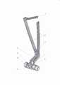
Сущность полезной модели поясняется чертежом, на котором изображена конструкция дистрактора и его расположение относительно расклиниваемых тел позвонков.The essence of the utility model is illustrated by a drawing, which shows the design of the distractor and its location relative to the wedged vertebral bodies.
Дистрактор позвоночника содержит бранши 1, скрепленные осью 2, на изогнутых концах 3 которых со стороны доступа к позвонкам расположены рабочие элементы 4 П-образной формы с ножками 5, изогнутыми перпендикулярно оси позвонков, соединяющимися площадкой-перемычкой 6, располагаемой на боковой поверхности тела позвонка. Противоположные прямые концы браншей, предназначенные для рук хирурга и обеспечивающие путем их сжатия расхождение рабочих элементов, снабжены фиксирующим элементом в виде кремальеры 7, позволяющей зафиксировать и сохранять достигнутое расклинивание тел позвонков во время операции.The spine distractor contains
На чертеже схематично показаны тела позвонков 8 с замыкательными пластинами 9.The drawing schematically shows the
Предложенный дистрактор используется следующим образом. Передним доступом обнажают тела позвонков. Межпозвоночные диски на нужном протяжении рассекают и иссекают до задних отделов фиброзного кольца. По показаниям возможно удаление тела пораженного позвонка. В образовавшиеся дефекты вставляют дистальные изогнутые концы 3 браншей 1 так, чтобы сведенные П-образные рабочие элементы 4 ножками 5 упирались в замыкательные пластины 9 тел смежных позвонков 8.The proposed distractor is used as follows. Vertebral bodies are exposed by anterior access. The intervertebral discs are dissected at the required length and excised to the posterior sections of the annulus fibrosus. According to the indications, it is possible to remove the body of the affected vertebra. The distal
Сжимая проксимальные концы браншеи, дают дистракцию, достигая расклинивания до нужной степени с напряжением растяжения до 80-100 кг (силы руки хирурга), затем с помощью фиксирующего механизма кремальеры 7 закрепляют полученное положение и переходят к установке трансплантата.By squeezing the proximal ends of the branch, they give distraction, achieving wedging to the desired degree with a tensile stress of up to 80-100 kg (the strength of the surgeon's hand), then, using the locking mechanism, the
Вынесенные примерно до середины тел раздвигаемых позвонков соединительные площадки-перемычки 6 П-образных рабочих элементов 4 позволяют контролировать состояние замыкательных пластин 9, проводить дополнительную их коррекцию, например создание паза для трансплантата без удаления дистрактора, и свободно установить костный трансплантат без потери достигнутого диастаза. В последующем, после удаления дистрактора, достигается эффект заклинивания трансплантата и компрессии на него с заданной силой за счет эластичности связочного аппарата позвоночника или напряжения транспедикулярной конструкции (при двухэтапном оперативном лечении) без использования дополнительного компрессионного устройства. Этим обеспечивается надежность установки трансплантата.The connecting platforms-
Таким образом, предложенная полезная модель позволяет эффективно осуществлять коррекцию позвоночника с выполнением переднего расклинивающего спондилодеза, обеспечивая удобство в работе хирурга и надежность установки между позвонками трансплантата с заданной силой компрессии.Thus, the proposed utility model allows for effective correction of the spine with anterior wedging fusion, providing convenience for the surgeon and reliability of graft placement between the vertebrae with a given compression force.
Claims (1)
Translated fromRussianPublications (1)
| Publication Number | Publication Date |
|---|---|
| RU214668U1true RU214668U1 (en) | 2022-11-09 |
Family
ID=
Citations (9)
| Publication number | Priority date | Publication date | Assignee | Title |
|---|---|---|---|---|
| SU1195991A1 (en)* | 1983-12-21 | 1985-12-07 | Ворошиловградский государственный медицинский институт | Arrangement for fixing vertebra (its versions) |
| US4733657A (en)* | 1984-04-16 | 1988-03-29 | Patrick Kluger | Apparatus for aligning a spinal column having damaged vertebrae |
| DE3711091A1 (en)* | 1987-04-02 | 1988-10-13 | Kluger Patrick | DEVICE FOR SETTING UP A SPINE WITH A DAMAGED SPINE |
| RU2085140C1 (en)* | 1992-01-16 | 1997-07-27 | Андрей Владимирович Кедров | Backbone distractor |
| US20050021040A1 (en)* | 2003-07-21 | 2005-01-27 | Rudolf Bertagnoli | Vertebral retainer-distracter and method of using same |
| US20070191856A1 (en)* | 2006-01-31 | 2007-08-16 | Sdgi Holdings, Inc. | Adjustable height spinal distractor |
| RU2312621C1 (en)* | 2006-07-19 | 2007-12-20 | Фарит Фагимович Мухаметов | Ventral distraction apparatus for spine |
| US8163020B2 (en)* | 2005-12-22 | 2012-04-24 | Creaspine | Assembly comprising an implant for replacing a vertebral body and a spinal distraction tool |
| US20170105770A1 (en)* | 2009-11-10 | 2017-04-20 | Nuvasive, Inc. | Method and Apparatus for Performing Spinal Surgery |
Patent Citations (9)
| Publication number | Priority date | Publication date | Assignee | Title |
|---|---|---|---|---|
| SU1195991A1 (en)* | 1983-12-21 | 1985-12-07 | Ворошиловградский государственный медицинский институт | Arrangement for fixing vertebra (its versions) |
| US4733657A (en)* | 1984-04-16 | 1988-03-29 | Patrick Kluger | Apparatus for aligning a spinal column having damaged vertebrae |
| DE3711091A1 (en)* | 1987-04-02 | 1988-10-13 | Kluger Patrick | DEVICE FOR SETTING UP A SPINE WITH A DAMAGED SPINE |
| RU2085140C1 (en)* | 1992-01-16 | 1997-07-27 | Андрей Владимирович Кедров | Backbone distractor |
| US20050021040A1 (en)* | 2003-07-21 | 2005-01-27 | Rudolf Bertagnoli | Vertebral retainer-distracter and method of using same |
| US8163020B2 (en)* | 2005-12-22 | 2012-04-24 | Creaspine | Assembly comprising an implant for replacing a vertebral body and a spinal distraction tool |
| US20070191856A1 (en)* | 2006-01-31 | 2007-08-16 | Sdgi Holdings, Inc. | Adjustable height spinal distractor |
| RU2312621C1 (en)* | 2006-07-19 | 2007-12-20 | Фарит Фагимович Мухаметов | Ventral distraction apparatus for spine |
| US20170105770A1 (en)* | 2009-11-10 | 2017-04-20 | Nuvasive, Inc. | Method and Apparatus for Performing Spinal Surgery |
Similar Documents
| Publication | Publication Date | Title |
|---|---|---|
| US20230240722A1 (en) | Expandable articulating intervertebral implant with limited articulation | |
| US7727279B2 (en) | Minimally invasive apparatus to manipulate and revitalize spinal column disc | |
| US20060276902A1 (en) | Minimally invasive apparatus to manipulate and revitalize spinal column disc | |
| US7879099B2 (en) | Minimally invasive apparatus to manipulate and revitalize spinal column disc | |
| US10016286B2 (en) | Method of inserting an interbody fusion device | |
| JP4500311B2 (en) | Artificial organ | |
| CA2368251C (en) | Shape memory alloy staple | |
| US20080091269A1 (en) | Minimally invasive apparatus to manipulate and revitalize spinal column disc | |
| US20070179611A1 (en) | Methods and devices for replacement of intervertebral discs | |
| JP2018175851A (en) | Expanding interbody implant and articulating inserter and method of use | |
| US9289248B2 (en) | Assembly with offset allowing vertebral distraction by axial rotation of a concentric member | |
| US20090292314A1 (en) | Lumbar interspinous prosthesis and its applications | |
| KR20090096609A (en) | Orthopaedic implants and prostheses | |
| EP0418387A1 (en) | Device for treatment of curvature of and damage to the spine | |
| CN109199560B (en) | Support capable of being spread and supporting bone grafting | |
| WO2011002847A1 (en) | Spine distraction and compression instrument | |
| KR20080085006A (en) | Assembly including vertebral replacement implants and spinal distraction devices | |
| JP2022046661A (en) | Hinged anterior cervical locking plate system | |
| RU214668U1 (en) | VENTAL SPINE DISTRACTOR | |
| RU2312621C1 (en) | Ventral distraction apparatus for spine | |
| RU2360648C1 (en) | Device for surgical treatment of backbone | |
| RU213473U1 (en) | Device for temporary intraoperative fixation of the vertebral bodies in the position of distraction during anterior interbody lumbar fusion | |
| US20090254127A1 (en) | Low profile implant locking plates | |
| US20230404627A1 (en) | A modified compression appliance and associated hardware for use in spinal surgery | |
| RU2362503C2 (en) | Gross scoliosis alignment technique |