RU2146327C1 - Methods for recovering oil from water-flooded hydrocarbon deposits by injection of cellulose - Google Patents
Methods for recovering oil from water-flooded hydrocarbon deposits by injection of celluloseDownload PDFInfo
- Publication number
- RU2146327C1 RU2146327C1RU96115004ARU96115004ARU2146327C1RU 2146327 C1RU2146327 C1RU 2146327C1RU 96115004 ARU96115004 ARU 96115004ARU 96115004 ARU96115004 ARU 96115004ARU 2146327 C1RU2146327 C1RU 2146327C1
- Authority
- RU
- Russia
- Prior art keywords
- powder
- water
- mixture
- dose
- injection
- Prior art date
Links
- 238000002347injectionMethods0.000titleclaimsabstractdescription86
- 239000007924injectionSubstances0.000titleclaimsabstractdescription86
- 238000000034methodMethods0.000titleclaimsabstractdescription39
- 229930195733hydrocarbonNatural products0.000titleclaimsabstractdescription20
- 150000002430hydrocarbonsChemical class0.000titleclaimsabstractdescription20
- 239000004215Carbon black (E152)Substances0.000titleclaimsdescription13
- 229920002678cellulosePolymers0.000titledescription14
- 239000001913celluloseSubstances0.000titledescription14
- XLYOFNOQVPJJNP-UHFFFAOYSA-NwaterSubstancesOXLYOFNOQVPJJNP-UHFFFAOYSA-N0.000claimsabstractdescription114
- 239000000843powderSubstances0.000claimsabstractdescription104
- 238000002156mixingMethods0.000claimsabstractdescription71
- 239000000203mixtureSubstances0.000claimsabstractdescription71
- 238000004519manufacturing processMethods0.000claimsabstractdescription24
- UFHFLCQGNIYNRP-UHFFFAOYSA-NHydrogenChemical compound[H][H]UFHFLCQGNIYNRP-UHFFFAOYSA-N0.000claimsabstractdescription18
- 230000015572biosynthetic processEffects0.000claimsdescription35
- 230000001276controlling effectEffects0.000claimsdescription21
- 230000001105regulatory effectEffects0.000claimsdescription18
- 239000012530fluidSubstances0.000claimsdescription10
- 239000000463materialSubstances0.000claimsdescription9
- 239000007788liquidSubstances0.000claimsdescription8
- 239000011261inert gasSubstances0.000claimsdescription7
- 238000012544monitoring processMethods0.000claimsdescription6
- 238000001914filtrationMethods0.000claimsdescription3
- 230000033228biological regulationEffects0.000claimsdescription2
- 230000005611electricityEffects0.000claimsdescription2
- 230000001419dependent effectEffects0.000claims3
- 239000011241protective layerSubstances0.000claims1
- 238000011084recoveryMethods0.000abstractdescription13
- 239000000126substanceSubstances0.000abstractdescription3
- 230000000694effectsEffects0.000abstractdescription2
- 235000010980celluloseNutrition0.000description13
- IJGRMHOSHXDMSA-UHFFFAOYSA-NAtomic nitrogenChemical compoundN#NIJGRMHOSHXDMSA-UHFFFAOYSA-N0.000description12
- 238000005516engineering processMethods0.000description12
- 230000006870functionEffects0.000description8
- 230000004044responseEffects0.000description7
- 230000000903blocking effectEffects0.000description6
- 229910052757nitrogenInorganic materials0.000description6
- 239000011435rockSubstances0.000description6
- 102000010637AquaporinsHuman genes0.000description5
- 238000010586diagramMethods0.000description5
- 230000008569processEffects0.000description5
- 239000007787solidSubstances0.000description5
- 230000008901benefitEffects0.000description4
- 239000000839emulsionSubstances0.000description4
- 229920000663Hydroxyethyl cellulosePolymers0.000description3
- 239000004354Hydroxyethyl celluloseSubstances0.000description3
- 239000000654additiveSubstances0.000description3
- 230000006378damageEffects0.000description3
- 238000011010flushing procedureMethods0.000description3
- 235000019447hydroxyethyl celluloseNutrition0.000description3
- 239000010410layerSubstances0.000description3
- 239000002245particleSubstances0.000description3
- 230000001960triggered effectEffects0.000description3
- CURLTUGMZLYLDI-UHFFFAOYSA-NCarbon dioxideChemical compoundO=C=OCURLTUGMZLYLDI-UHFFFAOYSA-N0.000description2
- 230000002411adverseEffects0.000description2
- QVGXLLKOCUKJST-UHFFFAOYSA-Natomic oxygenChemical compound[O]QVGXLLKOCUKJST-UHFFFAOYSA-N0.000description2
- -1carboxyalkyl ethersChemical class0.000description2
- 229920003086cellulose etherPolymers0.000description2
- 230000007423decreaseEffects0.000description2
- 238000011049fillingMethods0.000description2
- 238000012986modificationMethods0.000description2
- 230000004048modificationEffects0.000description2
- 239000001301oxygenSubstances0.000description2
- 229910052760oxygenInorganic materials0.000description2
- 229920000642polymerPolymers0.000description2
- 230000002028prematureEffects0.000description2
- 238000005086pumpingMethods0.000description2
- 238000003860storageMethods0.000description2
- LFQSCWFLJHTTHZ-UHFFFAOYSA-NEthanolChemical compoundCCOLFQSCWFLJHTTHZ-UHFFFAOYSA-N0.000description1
- 230000002159abnormal effectEffects0.000description1
- 238000009825accumulationMethods0.000description1
- 230000000996additive effectEffects0.000description1
- 239000012223aqueous fractionSubstances0.000description1
- 239000007864aqueous solutionSubstances0.000description1
- 229910002092carbon dioxideInorganic materials0.000description1
- 239000001569carbon dioxideSubstances0.000description1
- 239000011247coating layerSubstances0.000description1
- 238000004891communicationMethods0.000description1
- 238000005056compactionMethods0.000description1
- 238000007796conventional methodMethods0.000description1
- 238000001816coolingMethods0.000description1
- 238000005260corrosionMethods0.000description1
- 230000007797corrosionEffects0.000description1
- 238000005336crackingMethods0.000description1
- 230000003111delayed effectEffects0.000description1
- 238000013461designMethods0.000description1
- 238000011161developmentMethods0.000description1
- 239000000284extractSubstances0.000description1
- 238000000605extractionMethods0.000description1
- 239000000446fuelSubstances0.000description1
- 239000007789gasSubstances0.000description1
- 150000004677hydratesChemical class0.000description1
- 230000036571hydrationEffects0.000description1
- 238000006703hydration reactionMethods0.000description1
- 229920013821hydroxy alkyl cellulosePolymers0.000description1
- 229920003088hydroxypropyl methyl cellulosePolymers0.000description1
- 235000010979hydroxypropyl methyl celluloseNutrition0.000description1
- 230000006872improvementEffects0.000description1
- 238000012423maintenanceMethods0.000description1
- 238000005065miningMethods0.000description1
- 238000012856packingMethods0.000description1
- 239000003208petroleumSubstances0.000description1
- 229920002401polyacrylamidePolymers0.000description1
- 239000002861polymer materialSubstances0.000description1
- 230000009467reductionEffects0.000description1
- 230000001020rhythmical effectEffects0.000description1
- 239000004576sandSubstances0.000description1
- 238000007789sealingMethods0.000description1
- 230000011664signalingEffects0.000description1
- 230000000638stimulationEffects0.000description1
- 239000000725suspensionSubstances0.000description1
- 238000012360testing methodMethods0.000description1
- 210000002105tongueAnatomy0.000description1
- 238000012546transferMethods0.000description1
- 239000003981vehicleSubstances0.000description1
- 239000002699waste materialSubstances0.000description1
- 239000002351wastewaterSubstances0.000description1
- 239000002569water oil creamSubstances0.000description1
- 238000009736wettingMethods0.000description1
- 238000004804windingMethods0.000description1
Images


Classifications
- E—FIXED CONSTRUCTIONS
- E21—EARTH OR ROCK DRILLING; MINING
- E21B—EARTH OR ROCK DRILLING; OBTAINING OIL, GAS, WATER, SOLUBLE OR MELTABLE MATERIALS OR A SLURRY OF MINERALS FROM WELLS
- E21B33/00—Sealing or packing boreholes or wells
- E21B33/10—Sealing or packing boreholes or wells in the borehole
- E21B33/13—Methods or devices for cementing, for plugging holes, crevices or the like
- E21B33/138—Plastering the borehole wall; Injecting into the formation
Landscapes
- Geology (AREA)
- Life Sciences & Earth Sciences (AREA)
- Engineering & Computer Science (AREA)
- Mining & Mineral Resources (AREA)
- Environmental & Geological Engineering (AREA)
- Fluid Mechanics (AREA)
- Physics & Mathematics (AREA)
- General Life Sciences & Earth Sciences (AREA)
- Geochemistry & Mineralogy (AREA)
- Accessories For Mixers (AREA)
- Polysaccharides And Polysaccharide Derivatives (AREA)
- Pharmaceuticals Containing Other Organic And Inorganic Compounds (AREA)
- Medicinal Preparation (AREA)
- Feeding, Discharge, Calcimining, Fusing, And Gas-Generation Devices (AREA)
Abstract
Description
Translated fromRussianИзобретение относится к оборудованию и способу для извлечения нефти из затопленных водой углеводородных месторождений, и, в частности, к усовершенствованному способу затопления водой и оборудованию для увеличения эффективности операций извлечения нефти. The invention relates to equipment and a method for extracting oil from water-flooded hydrocarbon deposits, and, in particular, to an improved method of flooding with water and equipment to increase the efficiency of oil recovery operations.
Заполнение водой является стандартной технологией, используемой для повышения извлечения нефти из углеводородного месторождения. В обычном применении множество инжекционных скважин, расположенных с промежутком в более старых, до некоторой степени истощенных нефтяных месторождениях, используются для увеличения добычи нефти из добывающих скважин, также расположенных повсюду в месторождении. Вода под давлением течет из инжекционной скважины через проницаемую породу в направлении относительно слабонапорной добывающей скважины, которая извлекает нефть с той же самой водой, когда вода течет через породу или пласт в направлении добывающей скважины. Специалисты давно поняли, что хотя вода, текущая через пласт, обязательно несет некоторое количество нефти в добывающую скважину, она также имеет тенденцию все время течь по тем же самым образованным скважинам проточным каналам, что снижает эффективность операций добычи нефти. В результате течения воды по этим образованным проточным каналам, вода имеет тенденцию увлекать меньшую долю нефти, так что "водная фракция" полученных жидкостей в конечном счете превышает стоимость разделения полученной смеси нефть/вода в экономический продукт на основе углеводорода. Water filling is a standard technology used to increase oil recovery from a hydrocarbon field. In a typical application, a plurality of injection wells spaced apart in older, somewhat depleted oil fields, are used to increase oil production from production wells also located throughout the field. Water under pressure flows from an injection well through permeable rock in the direction of a relatively low-pressure producing well, which extracts oil with the same water when water flows through the rock or formation in the direction of the producing well. Specialists have long understood that although water flowing through the reservoir necessarily carries a certain amount of oil into the producing well, it also tends to flow through the same flow channels all the time, which reduces the efficiency of oil production operations. As a result of the flow of water through these formed flow channels, water tends to entrain a smaller proportion of oil, so that the “water fraction” of the resulting liquids ultimately exceeds the cost of separating the resulting oil / water mixture into a hydrocarbon-based economic product.
Для усовершенствования добычи нефти, использующей технологию затопления водой, специалисты признали выгодность блокирования образованных водяных каналов через пласт для того, чтобы вынудить инжектируемую воду найти новые каналы и посредством этого увлечь новую нефть, которая извлекается с водой. В патенте США 4194563 описана методика усовершенствования операции затопления водой путем инжектирования слоя эмульсии в каналы протекания в пласте, затем промывание буровой скважины спиртом для удаления эмульсии, образованной вблизи буровой скважины. В патенте США 4529523 исследован способ улучшения затопления водой путем использования оксиэтилцеллюлозы для предотвращения образования языков обводнения через существующие потоковые каналы в пласте. В патенте США 4903768 раскрыта методика регулирования профиля поверхности раздела нефть/вода в высокопроницаемой зоне при использовании в качестве управляющего процесса затопления водой или углекислотную стимуляцию. Прорыв запирали, используя активируемую температурой смесь, которая образует твердый блокирующий гель. To improve oil production using water flooding technology, experts recognized the advantage of blocking the formed water channels through the reservoir in order to force the injected water to find new channels and thereby entrain new oil that is extracted with water. US Pat. No. 4,194,563 describes a technique for improving the operation of flooding with water by injecting an emulsion layer into the flow channels in the formation, then flushing the borehole with alcohol to remove the emulsion formed near the borehole. US Pat. No. 4,529,523 teaches a method for improving water flooding by using hydroxyethyl cellulose to prevent the formation of waterlogging languages through existing flow channels in the formation. US Pat. No. 4,903,768 discloses a method for controlling the profile of an oil / water interface in a highly permeable zone when water flooding or carbon dioxide stimulation is used as a control process. The breakthrough was locked using a temperature-activated mixture that forms a solid blocking gel.
Специалисты в области затопления водой также поняли, что водонефтяная эмульсия может быть использована для запирания или по крайней мере уменьшения течения в сильнопористой зоне, посредством чего предотвращается нежелательное образование языков обводнения и улучшается течение углеводородов в добывающую скважину. В патенте США 3472319 исследована технология смешивания эмульсии нефти в воде с минимальной энергией сдвига. Смесь инжектируется в пласт в виде эмульсии с низкой вязкостью, так что капли нефти разбухают в пласте и запирают или частично запирают существующие водяные каналы. В патенте США 3724546 исследована смесь кровь-вода для операций затопления водой. Хотя использовались различные продукты для инжектирования с водой с тем, чтобы способствовать операции затопления водой посредством блокирования или частичного блокирования образованных потоков каналов, предпочтительным инжектируемым продуктом для многих применений затопления водой является целлюлоза. Использование целлюлозы в качестве материала, смешиваемого с водой, хорошо известно, как явствует из патентов США 3848673, 4321968, 4451389, 4627494, 4629575 и 5100576. Концентрация целлюлозы, которая инжектируется с водой в пласт, может изменяться. Путем оптимизации скорости инжектирован жидкости извлечение углеводородов может быть увеличено во время вторичного или третичного процесса извлечения. В патенте США 4374544 и Европейской публикации 48342 описана методика оптимизации скоростей инжектирования и в тоже время предотвращения растрескивания и разрушения пласта, которое может снизить эффективность процесса извлечения нефти. Specialists in the field of water flooding also realized that the oil-water emulsion can be used to shut off or at least reduce the flow in the highly porous zone, thereby preventing undesired formation of waterlog tongues and improving the flow of hydrocarbons into the producing well. US Pat. No. 3,472,319 teaches technology for mixing an oil emulsion in water with minimal shear energy. The mixture is injected into the formation in the form of an emulsion with a low viscosity, so that oil droplets swell in the formation and block or partially block the existing water channels. US 3,724,546 teaches a blood-water mixture for water flooding operations. Although various water injection products have been used to facilitate the water flooding operation by blocking or partially blocking the formed channel flows, cellulose is the preferred injection product for many water flooding applications. The use of cellulose as a water miscible material is well known, as is evident from US Pat. Nos. 3,848,673, 4321968, 4451389, 4627494, 4629575 and 5100576. The concentration of cellulose that is injected with water into the formation can vary. By optimizing the injected fluid rate, hydrocarbon recovery can be increased during the secondary or tertiary recovery process. In US patent 4374544 and European publication 48342 describes a technique for optimizing injection rates and at the same time preventing cracking and fracturing, which can reduce the efficiency of the oil recovery process.
Специалисты в области вторичного и третичного извлечения нефти в основном признают выгодность смонтированных на трейлере или прицепе смешивающих и инжекционных устройств, таких, как например описанных в статье, озаглавленной "Enhanced Recovery Requires Special Equipment", Oil and Gas Journal, July 12, 1976, pp. 50-56. В патенте США 4448535 Описан портативный аппарат для смешивания песков и твердых добавок при выбранных скоростях инжектирования с водой в скважину. Сухой химикат предпочтительнее подается в бак- мешалку, примыкающий к изменяемому соплу Вентури, в котором вода находится под низким давлением и сильно перемешивается. В Европейской патентной заявке N 91309842.2 раскрыта методика непрерывного перемешивания твердых частиц с жидкостью для облегчения операции гравитационного уплотнения. Для регулирования расхода твердых частиц используется бункер твердых частиц с внутренним шнеком, при этом жидкость направляется в смесительную камеру вокруг периферии шнека. В патенте США N 4311395 описана конструкция шасси для монтирования оборудования, используемого в операциях техобслуживания скважины. В патенте США N 4077428 раскрыта передвижная установка инжектирования воды для операций затопления водой. В патенте США N 4534869 описана фильтрационная система с трехстадийным фильтрующим процессом, используемая для заправочных операций. В патенте США N 4597437 раскрыто портативное устройство для провешивания и добычи, используемое в разработке углеводородов. Secondary and tertiary oil recovery experts generally recognize the utility of trailer and trailer mounted mixing and injection devices, such as those described in the article entitled "Enhanced Recovery Requires Special Equipment", Oil and Gas Journal, July 12, 1976, pp . 50-56. US Pat. No. 4,448,535 describes a portable apparatus for mixing sand and solid additives at selected injection rates with water in a well. The dry chemical is preferably fed to a blender adjacent to the variable Venturi nozzle, in which the water is under low pressure and is highly mixed. European Patent Application No. 91309842.2 discloses a method for continuously mixing solid particles with a liquid to facilitate gravitational compaction. To control the flow of solid particles, a solid particle bin with an internal screw is used, while the liquid is sent to the mixing chamber around the periphery of the screw. US Pat. No. 4,311,395 describes a chassis design for mounting equipment used in well maintenance operations. US Pat. No. 4,077,428 discloses a mobile water injection unit for water flooding operations. US Pat. No. 4,534,869 describes a filtration system with a three-stage filtering process used for refueling operations. US Pat. No. 4,597,437 discloses a portable suspension and production device used in the development of hydrocarbons.
В патенте США 4518261 описан способ растворения полиакриламидного порошка в водном растворе для увеличения добычи или извлечения нефти. Для того, чтобы предотвратить увеличение влажности и слеживание порошка может использоваться азотный слой. Полимеры, смешиваемые с инжектируемой водой, могут транспортироваться в миксер сухим воздухом, как описано в патенте США 4014527. Системы регулирования инжектирования гелеобразных жидкостей в скважину описаны в патенте США 3707191, а также в патентах США 4265266 и 4953618. Оборудование для смешивания сухого материала с водой описано в патентах США 3902558, 4357953, 4725379 и 5190374. US 4,518,261 describes a method for dissolving a polyacrylamide powder in an aqueous solution to increase oil production or recovery. In order to prevent an increase in humidity and caking of the powder, a nitrogen layer may be used. Polymers mixed with injected water can be transported to the mixer with dry air, as described in US Pat. No. 4,014,527. Control systems for injecting gelled liquids into a well are described in US Pat. No. 3,707,191, and also US Pat. Nos. 4,265,266 and 4,953,618. Equipment for mixing dry material with water described in US patent 3902558, 4357953, 4725379 and 5190374.
Хотя на усовершенствование добычи нефти с использованием технологии затопления водой было затрачено много усилий, дальнейшее усовершенствование этой технологии и связанное с ним снижение стоимости операций добычи являются весьма важными и необходимыми, если частично истощенные углеводородные месторождения начинают играть все возрастающую роль в удовлетворении дальнейших потребностей в нефти. В различных частях света существует огромное количество резервов нефти низкого давления, и для экономичной добычи этих резервов требуется разностороннее гибкое оборудование и усовершенствованные технологии. Although a lot of effort has been devoted to improving oil production using water flooding technology, further improvement of this technology and the associated reduction in the cost of production operations are very important and necessary if partially depleted hydrocarbon deposits begin to play an increasingly important role in meeting further oil needs. In various parts of the world there is a huge amount of reserves of low-pressure oil, and the economical production of these reserves requires versatile flexible equipment and advanced technologies.
Эти недостатки уровня техники преодолеваются настоящим изобретением и усовершенствованным оборудованием и технологией добычи нефти, описанные в настоящем описании для более эффективного извлечения нефти из истощенных месторождений. These disadvantages of the prior art are overcome by the present invention and the improved oil production equipment and technology described herein for more efficient recovery of oil from depleted fields.
Краткое описание изобретения
Согласно настоящему изобретению, порошок целлюлозы смешивается с водой, и смесь инжектируется через направленный вниз шпур в пласт или породу. Целлюлозный порошок гидратируется водой приблизительно тридцать минут после смешивания, когда вола, предпочтительнее, находится внутри пласта, с образованием высоковязкой смеси, которая блокирует старые водные каналы и посредством этого вынуждает инжектированную воду находить новые каналы через пласт, в результате увлекая больше нефти, которую она несет в направлении добывающей скважины. Порошок целлюлозы и инжектируемая вода смешиваются в слабовязкой вихревой смесительной камере, установленной на прицепе для облегчения транспортировки к различным местам скважины. Азотный покровный слой, предпочтительнее, используется для предотвращения увеличения влажности и исключения попадания кислорода в систему, что может нанести вред операциям добычи нефти или неблагоприятно воздействовать на пласт или пластовые жидкости.SUMMARY OF THE INVENTION
According to the present invention, the cellulose powder is mixed with water, and the mixture is injected through a downhole into a formation or rock. The cellulosic powder is hydrated with water for approximately thirty minutes after mixing, when the ox is preferably located inside the formation, with the formation of a highly viscous mixture that blocks the old water channels and thereby forces the injected water to find new channels through the formation, as a result entraining more of the oil that it carries in the direction of the producing well. Cellulose powder and injected water are mixed in a low viscosity vortex mixing chamber mounted on a trailer to facilitate transport to various locations in the well. A nitrogen coating layer is preferably used to prevent an increase in humidity and to prevent oxygen from entering the system, which could harm oil production operations or adversely affect the formation or formation fluids.
Способ по настоящему изобретению может быть использован для точного регулирования инжектирования порошка целлюлозы, а также оксиэтилцеллюлозы, в пласт для увеличения добычи нефти. Порошок целлюлозы может быть смешан с имеющейся в инжекционной скважине водой, и смесь закачивается через различные инжекционные скважины в пористые породы для эффективного блокирования образованных скважинами или существующих потоковых каналов. Гибкость компьютера позволяет легко приспособить систему к условиям определенной скважины и пласта. Точный контроль пропорции оксиэтилцеллюлозы с инжектируемой в скважину водой позволяет стабилизировать и оптимизировать сопротивление течению воды через пористую породу и, таким образом, минимизировать закорачивание воды из инжекционной скважины в продуктовую скважину и, соответственно, увеличить эффективность операций добычи нефти. The method of the present invention can be used to precisely control the injection of cellulose powder, as well as hydroxyethyl cellulose, into the formation to increase oil production. Cellulose powder can be mixed with the water available in the injection well, and the mixture is pumped through various injection wells into the porous rock to effectively block the formed wells or existing flow channels. The flexibility of the computer makes it easy to adapt the system to the conditions of a particular well and formation. Exact control of the proportion of hydroxyethyl cellulose with water injected into the well allows to stabilize and optimize the resistance to water flow through the porous rock and, thus, minimize the shorting of water from the injection well into the product well and, accordingly, increase the efficiency of oil production operations.
Настоящее изобретение использует специальное оборудование и технологию для определения необходимого расхода и необходимой дозировки целлюлозы для максимального увеличения необходимого блокирующего воздействия на образованные водой каналы. Согласно настоящему изобретению предусмотрена система регулирования для получения оператором входных данных и для определения адекватного расхода и необходимой концентрации целлюлозы для инжектирования с заданным расходом воды. Кольцевое и тюбинговое напорные давления воды являются управляемыми. Расход увеличивается от минимального до максимального допустимого насосным оборудованием, и напорное давление в системе трубопроводов регулируется для обеспечения возможности выбора правильного расхода в соответствии с возможностью скважины разгонять смесь. Скорость инжектирования целлюлозы увеличивается и/или уменьшается до тех пор, пока не будут достигнуты, но не превышены, максимальные кольцевое и тюбинговое напорные давления. Изменение скорости инжектирования целлюлозы, следовательно, создает необходимое запирающее воздействие на существующие водные каналы. Таким образом, способ настоящего изобретения увеличивает точность дозирования расхода порошка целлюлозы и обеспечивает полностью контроль и регистрацию для каждой инжекции. Для смешивания с водой с образованием смеси, закачиваемой в нисходящий шпур, также могут использоваться и другие полимеры, а не только целлюлоза. После смешивания и перед закачиванием в смеси целлюлозы с водой могут вводиться посредством химического инжекционного насоса любые добавки. The present invention uses special equipment and technology to determine the required flow rate and the required dosage of cellulose to maximize the necessary blocking effect on the channels formed by water. According to the present invention, a control system is provided for the operator to obtain input data and to determine an adequate flow rate and the required concentration of pulp for injection with a given flow rate. The annular and tubing pressurized water pressures are controllable. The flow rate increases from the minimum to the maximum allowable by the pumping equipment, and the pressure in the piping system is regulated to allow the selection of the correct flow rate in accordance with the ability of the well to disperse the mixture. The cellulose injection rate increases and / or decreases until the maximum annular and tubing delivery pressures are achieved, but not exceeded. Changing the injection rate of cellulose, therefore, creates the necessary locking effect on existing water channels. Thus, the method of the present invention increases the accuracy of dosing the flow rate of cellulose powder and provides full control and registration for each injection. Other polymers, not just cellulose, can also be used to mix with water to form a mixture pumped into a downhole. After mixing and before being pumped into a mixture of cellulose with water, any additives can be introduced by means of a chemical injection pump.
В пригодном варианте выполнения изобретения используется усовершенствованное оборудование для осуществления операций, включающее четыре передвижных модуля, каждый из которых взаимно связан посредством местных и централизованных регулирующих систем: 1) насосно-инжекционный трейлер; 2) трейлер смешивания и регулирования целлюлозы; 3) трейлер генерирования или использования энергии; 4) резервуар для сыпучего порошка. Давление инжектирования жидкости, температура и расходы могут быть измерены посредством соответствующего оборудования для регулирования и контроля, и сигналы от этого оборудования могут передаваться через дистанционный блок терминала в компьютер наблюдения и контроля. Система способна работать при температурах поверхности от -40oC до +40oC, тем самым увеличивая ее многосторонность.In a suitable embodiment of the invention, advanced equipment is used to carry out operations, including four mobile modules, each of which is mutually connected through local and centralized regulatory systems: 1) pump-injection trailer; 2) a trailer for mixing and regulating pulp; 3) a trailer for generating or using energy; 4) a reservoir for bulk powder. Liquid injection pressure, temperature, and flow rates can be measured using appropriate control and monitoring equipment, and signals from this equipment can be transmitted through a remote terminal unit to a monitoring and control computer. The system is able to operate at surface temperatures from -40o C to +40o C, thereby increasing its versatility.
Целью настоящего изобретения является создание усовершенствованного способа контроля различных условий инжектирования, как например, инжекционное давление скважины, расход инжектируемой жидкости и входная температура инжектируемой жидкости, и, в соответствии с этими условиями, регулирование скорости и величины дозы порошка, которые должны вызвать оптимальное блокирование образованных скважиной каналов для увеличения эффективности операций добычи. The aim of the present invention is to provide an improved method for controlling various injection conditions, such as, for example, injection pressure of a well, flow rate of an injected fluid and an inlet temperature of an injected fluid, and, in accordance with these conditions, controlling the speed and dose of the powder, which should cause optimal blocking of the well formed channels to increase the efficiency of mining operations.
Другой целью настоящего изобретения является создание многостороннего оборудования, которое может эффективно использоваться в различных местах нефтяного месторождения для более эффективного извлечения или добычи углеводородов. Another objective of the present invention is the creation of versatile equipment that can be effectively used in various places of the oil field for more efficient extraction or production of hydrocarbons.
Еще одной целью настоящего изобретения является создание усовершенствованной технологии и оборудования, посредством которых можно более эффективно добывать углеводороды из в какой-то степени истощенных нефтяных месторождений, в результате чего становится более эффективной добыча углеводородов, которые не могут быть добыты существующими технологиями. Another objective of the present invention is the creation of improved technology and equipment through which it is possible to more efficiently produce hydrocarbons from somewhat depleted oil fields, resulting in more efficient production of hydrocarbons that cannot be extracted by existing technologies.
Особенностью настоящего изобретения является то, что регулирование величины дозы, а также комбинации величины дозы и скорости порошка могут автоматически осуществляться для более легкого и недорогого достижения наиболее оптимальной скорости инжектирования. A feature of the present invention is that the regulation of the dose, as well as a combination of the dose and the speed of the powder can be automatically carried out to more easily and inexpensively achieve the most optimal injection speed.
Еще одним отличительным признаком настоящего изобретения является то, что оборудование для осуществления усовершенствованного способа затопления водой может быть передвижным, вследствие чего обеспечивается многосторонность оборудования. Большинство компонентов системы использовались отдельно и испытаны в предыдущих операциях по добыче нефти, так что надежность системы является высокой и стоимость оборудования является сравнительно низкой. Another hallmark of the present invention is that the equipment for implementing the improved method of flooding with water can be mobile, as a result of which the versatility of the equipment is ensured. Most of the system components were used separately and tested in previous oil production operations, so the reliability of the system is high and the cost of equipment is relatively low.
Преимуществом настоящего изобретения является то, что способ определения правильной величины дозы хорошо подходит для различных порошковых полимерных материалов, которые служат для блокирования образованных скважинами потоковых каналов при инжектировании с водой в пласт. Способ дозирования по настоящему изобретению особенно хорошо подходит для использования с целлюлозным материалом, который широко применяется в качестве добавки при смешивании с водой для осуществления технологии затопления водой. An advantage of the present invention is that the method of determining the correct dose is well suited for various powder polymer materials, which serve to block the flow channels formed by the wells during injection with water into the formation. The dispensing method of the present invention is particularly well suited for use with cellulosic material, which is widely used as an additive when mixed with water to implement water flooding technology.
Другим преимуществом настоящего изобретения является то, что оборудование может надежно работать в широком диапазоне температур и особенно хорошо приспособлено для использования в нефтяных месторождениях, имеющих относительно низкие окружающие температуры. Another advantage of the present invention is that the equipment can operate reliably over a wide temperature range and is particularly well suited for use in oil fields having relatively low ambient temperatures.
Дополнительным преимуществом настоящего изобретения является то, что используемый способ также может оптимизировать инжектирование путем сочетания параметров скорости и величины дозы для того, чтобы получить наилучшие условия смешивания инжектируемой смеси для отдельной инжекционной скважины. An additional advantage of the present invention is that the method used can also optimize injection by combining speed parameters and dose values in order to obtain the best conditions for mixing the injected mixture for a single injection well.
Таким образом в соответствии с настоящим изобретением создан способ контроля инжектирования водопорошковой смеси через инжекционную скважину в пласт для добычи углеводородов, включающий:
(а) определение необходимой скорости инжектирования смеси;
(б) выбор исходной величины порошка;
(в) смешивание выбранной исходной дозы порошка с водой с получением исходного соотношения порошок-вода в смеси;
(г) инжектирование водопорошковой смеси через инжекционную скважину в пласт;
(д) контроль давления водопорошковой смеси в буровой скважине в окрестности пласта в течение этапа (г);
(е) увеличение заданной исходной величины дозы порошка для увеличения соотношения порошок-вода в водопорошковой смеси;
(ж) определение наибольшей величины порошка, полученной при достижении регулируемого давления заданного предела;
(з) после этого установка величины дозы между исходной величиной дозы и наибольшей величиной дозы для инжектирования смеси в пласт.Thus, in accordance with the present invention, a method for controlling the injection of a water-powder mixture through an injection well into a hydrocarbon production formation is created, comprising:
(a) determining the required injection rate of the mixture;
(b) the choice of the initial value of the powder;
(c) mixing the selected initial dose of the powder with water to obtain an initial powder-water ratio in the mixture;
(d) injection of the powder mixture through the injection well into the formation;
(e) monitoring the pressure of the water-powder mixture in the borehole in the vicinity of the formation during step (d);
(e) increasing the predetermined initial value of the dose of the powder to increase the ratio of powder to water in the water-powder mixture;
(g) determining the largest amount of powder obtained when the controlled pressure reaches a predetermined limit;
(h) after that setting the dose between the initial dose and the highest dose for injecting the mixture into the formation.
Согласно второму аспекту настоящего изобретения создана системы контроля инжектирования водо-порошковой смеси через инжекционную скважину в пласт для добычи углеводородов, содержащая:
смесительный бак для смешивания заданной исходной дозы порошка с водой с образованием исходной смеси с исходным соотношением порошок-вода;
датчик давления для контроля давления смеси в буровой скважине;
средство регулирования жидкости для поддержания необходимой скорости потока смеси в инжекционной скважине; расходомер для контроля расхода смеси, инжектируемой в инжекционную скважину;
регулирующее дозирующее средство для автоматического увеличения выбранной исходной лозы порошка со скоростью, являющейся функцией регулируемого давления и регулируемого расхода.According to a second aspect of the present invention, there is provided a system for controlling the injection of a water-powder mixture through an injection well into a hydrocarbon production formation, comprising:
a mixing tank for mixing a predetermined initial dose of powder with water to form an initial mixture with an initial powder-water ratio;
pressure sensor for monitoring the pressure of the mixture in the borehole;
fluid control means to maintain the necessary flow rate of the mixture in the injection well; a flow meter to control the flow rate of the mixture injected into the injection well;
a regulating dosing means for automatically increasing the selected initial powder vines at a speed that is a function of the controlled pressure and the controlled flow.
Согласно третьему аспекту настоящего изобретения создана система контроля инжектирования водопорошковой смеси через инжекционную скважину в пласт для добычи углеводородов, содержащая:
передвижную цистерну для накопления порошка целлюлозы;
передвижной бункер для хранения порошка целлюлозы;
передвижной источник сжатого воздуха для транспортирования порошка целлюлозы из резервуара в бункер;
передвижной смесительный бак для смешивания выбранной исходной дозы порошка с водой с получением смеси с исходным соотношением порошок-вода;
передвижной конвейер для транспортирования порошка целлюлозы из бункера в смесительный бак;
датчик давления для регулирования давления смеси в канале скважины;
расходометр для регулирования расхода смеси, инжектируемой в инжекционную скважину; и
регулирующее дозирующее средство для автоматического увеличения выбранной исходной дозы порошка со скоростью, являющейся функцией регулируемого давления и регулируемого расхода, при этом регулирующее средство содержит средство для регулирования скорости порошка вдоль конвейера.According to a third aspect of the present invention, there is provided a control system for injecting a powder mixture through an injection well into a hydrocarbon production reservoir, comprising:
a mobile tank for the accumulation of cellulose powder;
mobile hopper for storing cellulose powder;
a mobile source of compressed air for transporting cellulose powder from the tank to the hopper;
a mobile mixing tank for mixing the selected initial dose of powder with water to obtain a mixture with an initial ratio of powder to water;
a mobile conveyor for transporting cellulose powder from the hopper to the mixing tank;
pressure sensor for regulating the pressure of the mixture in the borehole channel;
a flowmeter for controlling the flow rate of the mixture injected into the injection well; and
regulating dosing means for automatically increasing the selected initial dose of the powder at a speed that is a function of the regulated pressure and the regulated flow, while the regulating means comprises means for controlling the speed of the powder along the conveyor.
Согласно дополнительному аспекту изобретения создан способ добычи нефти из углеводородных месторождений, который включает нагнетание смеси гелеобразующего материала с водой в нисходящий шпур, так что гелеобразующий материал гидратируется с образованием вязкого геля после нагнетания, при этом этот способ дополнительно включает контроль противодавления смеси и изменение в ответ на это концентрации гелеобразующего материала в смеси для измерения вязкости геля в нисходящем шпуре. According to a further aspect of the invention, there is provided a method for producing oil from hydrocarbon deposits, which comprises injecting a mixture of gelling material with water into a downhole so that the gelling material hydrates to form a viscous gel after injection, the method further comprising controlling the back pressure of the mixture and changing in response to these are the concentrations of the gelling material in the mixture to measure the viscosity of the gel in a downhole.
Краткое описание чертежей
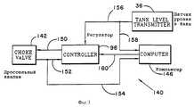
Фиг. 1 является схематическим изображением передвижного оборудования, согласно настоящему изобретению, для получения воды из питающего трубопровода, для добавления необходимого количества порошка целлюлозы в воду и для инжектирования водопорошковой смеси в инжекционную скважину для затопления водой.Brief Description of the Drawings
FIG. 1 is a schematic illustration of a mobile equipment according to the present invention for receiving water from a feed pipe, for adding the necessary amount of cellulose powder to water, and for injecting a powder mixture into an injection well for flooding with water.
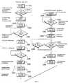
Фиг. 2 является блок- схемой соответствующей регулирующей логической схемы для регулирования шнекового конвейера, показанного на фиг. 1. FIG. 2 is a block diagram of a corresponding control logic for adjusting the screw conveyor shown in FIG. 1.
Фиг. 3 является блок-схемой соответствующей регулирующей логической схемы для регулирования дроссельного клапана, показанного на фиг. 1. FIG. 3 is a block diagram of a corresponding control logic for regulating the throttle valve shown in FIG. 1.
Фиг. 4 является блок-схемой соответствующей логической схемы для регулирования перемещения порошка целлюлозы согласно настоящему изобретению. FIG. 4 is a block diagram of a corresponding logic circuit for controlling the movement of cellulose powder according to the present invention.
Фиг. 5 является блок-схемой соответствующей логической схемы для эксплуатации инжекционных насосов, показанных на фиг. 1. FIG. 5 is a block diagram of a corresponding logic circuit for operating the injection pumps shown in FIG. 1.
Фиг. 6 является блок-схемой соответствующей логической схемы для регулирования дозирования целлюлозы согласно настоящему изобретению. FIG. 6 is a block diagram of a corresponding logic circuit for controlling the dosing of cellulose according to the present invention.
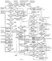
Фиг. 7 изображает график автоматического поиска величины дозы порошка как функции времени согласно изобретению. FIG. 7 is a graph for automatically searching for a dose of a powder as a function of time according to the invention.
Фиг. 8 является альтернативным графиком величины дозы порошка как функции времени достижения верхнего предела давления в устье скважины. FIG. 8 is an alternative plot of powder dose as a function of time to reach the upper pressure limit at the wellhead.
Подробное описание изобретения
На фиг. 1 схематически изображен один вариант выполнения комплекта оборудования, согласно настоящему изобретению, для осуществления операции затопления водой для добычи нефти из частично истощенных низконапорных месторождений. Комплект 10 является передвижным, так что оборудование может быть легко перевезено от одной инжекционной скважины к другой и/или из одного месторождения в другое, вследствие чего снижается общая стоимость оборудования. Основные компоненты комплекта 10 смонтированы на четырех трейлерах или тягачах с прицепом: насосно-энергетический трейлер 12, трейлер 14 смешивания целлюлозы и контроля, генераторно-энергетический трейлер 16 и насыпной трейлер 18. Каждый трейлер может быть обычным транспортным трейлером или тягачом с прицепом, который, соответственно, может быть легко помещен в нужное место на месторождении. Операции затопления водой используют доступные и имеющиеся в распоряжении водные источники, которые могут быть отведены от местных сетей трубопроводов водоснабжения. Комплект 10 смешивает воду с порошком целлюлозы и инжектирует смесь вниз в одну из множества селективно расположенных инжекционных скважин 1, так что из месторождения может быть добыто больше нефти. В зависимости от определенного типа используемой технологии затопления водой нефть может одновременно добываться из одной или более добывающих скважин (на чертеже не показаны), расположенных повсюду в месторождении.DETAILED DESCRIPTION OF THE INVENTION
In FIG. 1 schematically depicts one embodiment of a set of equipment according to the present invention for performing a water flooding operation to extract oil from partially depleted low pressure fields. The kit 10 is mobile so that the equipment can be easily transported from one injection well to another and / or from one field to another, thereby reducing the total cost of the equipment. The main components of kit 10 are mounted on four trailers or towing vehicles with a trailer: a power-pump trailer 12, a pulp mixing and control trailer 14, a power-generating trailer 16 and a bulk trailer 18. Each trailer can be a conventional transport trailer or tractor-trailer, which, accordingly, can be easily placed at the right place in the field. Water flooding operations use accessible and available water sources that can be diverted from local water supply pipeline networks. Kit 10 mixes water with cellulose powder and injects the mixture down into one of a plurality of selectively located
Полученная из источников водоснабжения вода (производственная вода, сточные воды, речная вода или смесь из одного или более этих источников питания водой) может поддерживаться под давлением с помощью специального соответствующего оборудования, не показанного на фиг. 1. Вода под давлением, используемая для инжектирования, сначала регулируется по давлению дроссельным клапаном 31, который автоматически реагирует на уровень регулирующего устройства 36, предусмотренного на смесительном баке 35 для поддержания необходимого уровня воды в смеситель ном баке. Перед пропусканием в бак 35 воду, предпочтительнее, фильтруют для снижения износа оборудования и повреждения пласта, и поэтому между дроссельным или запорным клапаном 31 и смесительным баком 35 предусмотрены подходящие соответствующие гидроциклонные фильтры 32. На трейлере 14 также может быть предусмотрен скип 67 для отходов для накопления выбросов из фильтров 32. Между фильтрами 32 и баком 35 расположен в параллель верхний нагнетательный регулирующий клапан 33 и нижний нагнетательный регулирующий клапан 34, и оператор может регулировать каждый клапан как функцию необходимой скорости инжектируемой воды для создания вихря в смесительном баке 35. Поэтому оператор определяет необходимую скорость инжектирования в инжекционную скважину, используя обычные методики, и затем регулирует контрольные клапаны для обеспечения необходимой скорости. Поскольку добавляемое количество дозируемого материала относительно невелико, необходимая или оптимальная скорость инжектирования равна, для практических целей, необходимой или оптимальной скорости течения воды в смесительный бак. Water obtained from water supply sources (process water, waste water, river water, or a mixture of one or more of these water supply sources) can be maintained under pressure using special suitable equipment not shown in FIG. 1. The pressurized water used for injection is first pressurized with a throttle valve 31, which automatically responds to the level of the
Водно-целлюлозная смесь из смесительного бака 35 проходит через расходомер 44 и затем к насосному трейлеру 12, где смесь сжимают до определенно выбранного давления посредством одного или двух инжекционных насосов 45, расположенных в параллель на трейлере 12. Затем смесь передается через серию обычных клапанов в выбранную инжекционную скважину 13, как показано на фиг. 1. Смесь инжектируется в пласт и проталкивается в направлении добывающих скважин инжектированной водой, служащей для улавливания нефти в пласте и переноса ее в направлении добывающих скважин. Согласно настоящему изобретению целлюлоза диспергируется в воду с необходимой скоростью в смесительном баке 35, но гидратация задерживается благодаря процессу смешивания. Каждый инжекционный насос приводится в действие двигателем 78 с изменяемой скоростью, так что необходимая скорость инжектирования для отдельной скважины может быть достигнута путем регулирования скорости насосов 45. Каждый основной насос 45 может, следовательно, снабжаться энергией посредством двигателя 78 с бифилярной обмоткой, так что каждый насос может работать при двух различных скоростях насоса. Альтернативно каждый насос 45 может работать с непрерывно изменяющейся скоростью, если используется приводной двигатель с изменяющейся скоростью. The cellulosic mixture from the mixing tank 35 passes through a
Насыпной трейлер 16 включает обычную цистерну 51 для хранения порошка целлюлозы. Сжатый воздух из генераторного трейлера 16 герметизирует цистерну 51 до необходимого уровня давления, т.е. несколько ниже, чем давление окружающей среды. Для регулирования уровня порошка внутри цистерны 51 предусмотрены датчики 52. Регулятор 64 давления и регулирующее поток отверстие или дроссель 63 на трейлере 14, следовательно, могут настраиваться для установления давления воздуха в цистерне 51 на необходимом уровне. Давление жидкости внутри цистерны может управляться посредством датчика 53 давления. На насыпном трейлере 18 могут быть предусмотрены баллоны 85 с азотом для обработки порошка в цистерне 51 инертным газом, если порошок не подается в бункер 42. В ответ на сигнал от порошкового бункера 42 один из продуктовых клапанов 55 открывается для подачи порошка из цистерны 51 через гибкий трубопровод 95 в питающий бункер 42. Bulk trailer 16 includes a conventional cellulose powder storage tank 51. Compressed air from the generator trailer 16 seals the tank 51 to the desired pressure level, i.e. slightly lower than ambient pressure. Sensors 52 are provided to control the level of powder inside the tank 51. The pressure regulator 64 and the flow-regulating hole or throttle 63 on the trailer 14 can therefore be adjusted to set the air pressure in the tank 51 to the required level. The fluid pressure inside the tank can be controlled by a pressure sensor 53. Cylinders 85 with nitrogen can be provided on the bulk trailer 18 for treating the powder in the tank 51 with inert gas if the powder is not supplied to the hopper 42. In response to the signal from the powder hopper 42, one of the product valves 55 opens to supply powder from the tank 51 through a flexible line 95 to the feed hopper 42.
Для регулирования давления в гибком трубопроводе 95 могут использоваться нагнетательные регулирующие клапаны 59 и 62. Контроль потока регулируемого воздуха также может осуществляться посредством соответствующего сопла 97 для обеспечения постоянного давления воздушного дутья, более высокого, чем давление присутствующего в цистерне воздуха. Псевдоожиженная набивка 54 в цистерне 51 поддерживает течение тонкого порошка к нагнетательным клапанам. Во время запуска или если потоковый трубопровод к бункеру 42 должен быть заглушен, нагнетательные клапаны 55 могут быть заперты, и только сжатый воздух продувается в транспортный трубопровод 95. Когда уровень порошка в бункере 42 падает ниже нижнего уровня переключателя 40, порошковые регулирующие клапаны 60 и 61 открываются для начала воздушного дутья в транспортный трубопровод 95. После заданного промежутка времени, т.е. двух секунд, нагнетательные клапаны 55 открываются. Затем порошок подается в бункер 42 до тех пор, пока переключатель 41 верхнего уровня не покроется порошком (или альтернативно после истечения заданного периода времени), в течение этого промежутка времени нагнетательные клапаны 55 заперты и транспортный трубопровод 95 прочищается сжатым воздухом. Pressure regulating valves 59 and 62 can be used to control the pressure in the flexible conduit 95. The controlled air flow can also be controlled by means of a corresponding nozzle 97 to ensure a constant air blast pressure higher than the pressure present in the air tank. The fluidized packing 54 in the tank 51 supports the flow of fine powder to the discharge valves. During start-up, or if the flow line to hopper 42 needs to be shut off, discharge valves 55 can be locked and only compressed air is blown into transport line 95. When the powder level in hopper 42 falls below the lower level of switch 40, the powder control valves 60 and 61 open to start air blast into the transport pipeline 95. After a predetermined period of time, i.e. two seconds, pressure valves 55 open. Then the powder is fed into the hopper 42 until the upper level switch 41 is covered with powder (or alternatively after a predetermined period of time has elapsed), during this time, the discharge valves 55 are closed and the transport pipe 95 is cleaned with compressed air.
Необходимая доза порошка подается в цистерну 35 из бункера 42 шнековым конвейером 39 и вибрационным столом 37, упрощенно показанным на фиг. 1. Шнековый конвейер 39 с переменной скоростью калибруется для подачи порошка в смесительный бак с необходимой величиной дозы. Смесительный бак 35 имеет два расположенных под углом ввода воды, каждый из которых сообщен по жидкости с одним из клапанов 33 и 34 для создания вихря внутри смесительного бака. Один или оба клапана 33 и 34 могут быть открыты оператором в зависимости от необходимой скорости течения воды в смесительный бак и, следовательно, в инжекционную скважину. Порошок целлюлозы с вибрационного стола может добавляться в центр вихря для обеспечения равномерного смешивания порошка с водой. Порошок остается в смесительном баке в течение, по существу, одинакового и непродолжительного промежутка времени перед выпуском в насосы 45. The required dose of powder is supplied to the tank 35 from the hopper 42 by a screw conveyor 39 and a vibration table 37, which is simplified shown in FIG. 1. The screw conveyor 39 with a variable speed is calibrated to feed the powder into the mixing tank with the required dose. The mixing tank 35 has two angled inlet water, each of which is in fluid communication with one of the valves 33 and 34 to create a vortex inside the mixing tank. One or both of the valves 33 and 34 can be opened by the operator depending on the required flow rate of water into the mixing tank and, therefore, into the injection well. Cellulose powder from a vibrating table can be added to the center of the vortex to ensure uniform mixing of the powder with water. The powder remains in the mixing tank for essentially the same and short period of time before being discharged into the pumps 45.
Панель 66 управления на трейлере 14 включает основной или компьютер 82 наблюдения и контроля, персональный компьютер 84 с клавиатурой ввода данных и слышимое и видимое сигнальное устройство 86. Компьютер 82 получает от расходомера 44 сигнал о расходе и передает сигнал о расходе порошка шнековому конвейеру с изменяемой скоростью 39 для подачи порошка в смесительный бак 35 с необходимой величиной дозы. Сигнал необходимой величины дозы может быть выражен как функция процентной величины дозы, умноженной на сигнал расхода от расходомера 44, и затем деленный на постоянную величину, которая определяется калибровкой определенного используемого продукта, с получением сигнала расхода порошка, который регулирует обороты конвейера 39 для подачи необходимого количества порошка для смешивания с инжектируемой водой. Taxoконтур 38 обратной связи обеспечивает достижение правильной скорости конвейера. Компьютер 82 и тахоконтур 38 таким образом регулируют скорость, с которой порошок добавляется к инжектируемой воде, и управляет скоростью добавления порошка и реальной скоростью конвейера для обеспечения необходимой величины дозы. Воздушное пространство 94 над водой в смесительном баке 35, предпочтительнее, герметизируется азотом или другим инертным газом для обеспечения подавления роста влажности, поскольку преждевременное увлажнение порошка вредно воздействует на работу системы. Покровный слой азота в пространстве 94 также гарантирует, что кислород не будет увлечен смесью инжектируемой воды с порошком, вследствие чего сводится к минимуму корродирование трубчатых обсадных колонн в инжекционной скважине и в добывающих скважинах, а также разрушение пласта и пластовых жидкостей. Азот может подаваться в бак 35 из баллонов 43, установленных на трейлере 14. Уровень воды в смесительном баке 35 регулируется дроссельным клапаном 31, который, в конечном счете, регулируется регулятором 96 дроссельного клапана. Как поясняется далее, регулятор 96 получает сигнал от датчика уровня в смесительном баке 35 и сравнивает сигнал датчика с сигналом требуемого уровня в смесительном баке, посылаемым в регулятор компьютером 82. The control panel 66 on the trailer 14 includes a main or monitoring and control computer 82, a personal computer 84 with a data input keyboard and an audible and visible signal device 86. Computer 82 receives a flow signal from the
Для генерирования электроэнергии на трейлере 16 установлены два дизельных генератора 75 и 76, при этом каждый генератор питается топливом из дизельного бака 71. Для ритмичного заполнения бака 71 предусмотрен дизельный транспортный блок 80. В соответствующем примере генератор 75 может быть 15-киловаттным генератором с воздушным охлаждением, подающим однофазный переменный ток напряжением 220 вольт, тогда как генератор 76 является 395-киловаттным генератором с воздушным охлаждением, подающим трехфазный ток напряжением 380 вольт и однофазный ток напряжением 220 вольт. Температура генератора 76 должна быть выше -10oC перед его запуском, и, соответственно, генератор 75 может быть сначала запущен при более холодной температуре, и энергия от генератора 75 используется для нагрева масляного зумпфа генератора 76 перед запуском генератора 76. Специалисты должны понимать, что генераторы 75 и 76 могут быть не нужны, если продуктовое месторождение расположено вблизи другого источника энергии, например, источника переменного тока напряжением 380 вольт. Панель 73 управления генератора смонтирована на трейлере 16 и включает компьютер 88, регуляторы 90 насоса и регуляторы 92 двигателя.To generate electricity, two diesel generators 75 and 76 are installed on the trailer 16, and each generator is supplied with fuel from the diesel tank 71. A diesel transport unit 80 is provided for rhythmic filling of the tank 71. In the corresponding example, the generator 75 may be a 15-kilowatt air-cooled generator supplying a single-phase alternating current voltage of 220 volts, while the generator 76 is a 395-kilowatt generator with air cooling, supplying a three-phase current voltage of 380 volts and a single-phase
Генераторы 75 и 76 поэтому питают электроэнергией запасные батареи, которые также служат в качестве источников постоянного тока. Двигатели насосов (на чертеже не показаны), которые могут быть использованы на любом из трейлеров запитываются генераторами. Датчик 98 может использоваться для зарядки запасных батарей 74. Поэтому для приведения в действие двигателей 78 имеется в распоряжении трехфазный ток напряжением 380 вольт и двигатель (на чертеже не показан), который запитывает воздушный компрессор 56, который герметизирует приемник или бак 57, также запитывается этим током. The generators 75 and 76 therefore power the spare batteries, which also serve as direct current sources. Pump motors (not shown in the drawing) that can be used on any of the trailers are powered by generators. The sensor 98 can be used to charge spare batteries 74. Therefore, to drive the motors 78, a three-phase current of 380 volts is available and a motor (not shown) that powers the air compressor 56, which seals the receiver or tank 57, is also powered by this electric current.
Однофазное напряжение 220 вольт может использоваться схемой регулирования насоса для приведения в действие двигателей шнекового конвейера 39 и запитывания источника постоянного тока для запасных батарей 74. Энергия от источника постоянного тока с напряжением 24 вольта может использоваться для схемы регулирования и питания компьютеров. Хотя это не показано на фиг. 1, специалисты должны понимать, что генераторный трейлер 16 также может включать обычное силовое и управляющее двигателями оборудование, а также автоматически выключающее оборудование. A single-phase voltage of 220 volts can be used by a pump control circuit to drive the motors of the screw conveyor 39 and power a DC source for spare batteries 74. Energy from a 24-volt DC source can be used to control and power computers. Although not shown in FIG. 1, specialists should understand that the generator trailer 16 may also include conventional power and engine control equipment, as well as automatically turning off the equipment.
На насосном трейлере предусмотрен бак 46 промывной жидкости, обеспечивающий источник питания водой в случае потери питания от ожидаемого источника воды, и обеспечивающий воду для промывки инжекционной скважины и промывки оборудования перед перемещением оборудования. Струйный насос 47 регулируется разгрузочными регулирующими клапанами 107 на трейлере 12. Также предусмотрена автоматическая разгрузочная система для снижения энергии, необходимой для запуска насосов 45. Оборудование, показанное на фиг. 1, сконструировано для снижения вероятности случайного смешивания порошка с водой перед запланированным смешиванием в смесительном баке 35, с тем, чтобы смесь поступала в необходимое место в пористой породе и не оседала преждевременно. Комплект оборудования, показанный на фиг. 1, однако, сконструирован также для быстрого демонстрирования с тем, чтобы пробки, вызванные преждевременным оседанием, можно было легко прочистить, и система могла нормально функционировать. A pumping fluid tank 46 is provided on the pump trailer, providing a water supply in the event of a loss of power from an expected water source, and providing water for flushing the injection well and flushing the equipment before moving the equipment. The jet pump 47 is controlled by pressure relief valves 107 on the trailer 12. An automatic discharge system is also provided to reduce the energy needed to start the pumps 45. The equipment shown in FIG. 1, is designed to reduce the likelihood of accidentally mixing the powder with water before scheduled mixing in the mixing tank 35, so that the mixture enters the desired location in the porous rock and does not settle prematurely. The set of equipment shown in FIG. 1, however, is also designed for quick demonstration so that plugs caused by premature subsidence can be easily cleaned and the system can function normally.
На фиг. 2 изображена соответствующая регулирующая схема 110 для регулирования скорости двигателя 116, который приводит в движение конвейер 39, показанный на фиг. 1. Панель 114 управления, схематически изображенная на фиг. 2, может быть персональным компьютером 84, показанным на фиг. 1, и компьютером 112, изображенным аналогичным образом на фиг.2, может быть компьютером 82, показанным на фиг. 1. Компьютер 112 генерирует сигнал требуемой величины дозы Qhr, который передается как сигнал 120 на панель 114 управления. Расходомер 44, следовательно, генерирует сигнал расхода Q, который показан на фиг.2 как 128, при этом этот сигнал является входным для компьютера 112. Тот же самый сигнал расхода Q также является входным сигналом 130 для панели 114 управления. Панель 114 управления генерирует дозирующий сигнал 122 для двигателя 116 шнекового конвейера, при этом сигнал 122 является функцией Qhr сигнала 120 и сигнала расхода 130. Сигнал 122, следовательно, служит для регулирования работы двигателя 116 с необходимой скоростью. Шнековый конвейер 38 тахо на фиг.1 генерирует сигнал 124 контура обратной связи на панель 114 управления для обеспечения работы конвейера с необходимой скоростью. Скорость двигателя 116 конвейера также вводится в компьютер 112, как сигнал 126, и служит в качестве проверочного для правильного определения величины дозы. Компьютер 112 может привести в действие сигнальное устройство 86 (фиг. 1), если реальная скорость двигателя 116 не соответствует, в заданном диапазоне необходимой величины дозы порошка в смесительном баке 35. In FIG. 2 depicts a
На фиг. 3 изображена соответствующая схема регулирования потока воды в смесительный бак 35. Сигнал уровня в баке 156 передается от датчика 36 регулятору 96 дроссельного клапана, и аналогичный сигнал 158 передается компьютеру 146, который функционально может быть компьютером 82, показанным на фиг. 1. Регулятор 96 выдает регулирующий сигнал 150 дроссельному клапану 31 для регулирования расхода жидкости в смесительном баке. Дроссельный клапан 31 имеет индикатор 142 положения клапана, который передает сигнал положения клапана 152 регулятору 96 для управления реальным положением дросселя и обеспечения того, что клапан правильно позиционирован регулятором. Этот же самый сигнал положения клапана может передаваться как сигнал 154 компьютеру 146, с тем, чтобы компьютер 146 мог сравнивать сигналы 158 и 154 и затем генерировать сигнал необходимого уровня в смесительном баке 160 регулятору 96. Регулятор 96 получает сигнал 156 от датчика 36 уровня и сравнивает этот сигнал с входным сигналом необходимого уровня в смесительном баке 160 из компьютера 146. Выходной сигнал 150 от регулятора 96 передается как сигнал положения дросселя 154 обратно компьютеру 146, так что компьютер 146 в действительности получает и сигнал уровня в баке, и сигнал регулирующего дроссельного клапана для обеспечения контроля и функционирования сигнального устройства. In FIG. 3 shows a corresponding circuit for regulating the flow of water into the mixing tank 35. The level signal in the
На фиг. 4 изображена соответствующая схема 170 регулирования перемещения порошка из цистерны 51 и бункер 42. Работа начинается на ступени 172 запуска, и компаратор 174 сначала определяет, что давление Рt в цистерне меньше, чем заданное значение, которое может быть выбрано равным 1.1 Ва. Если давление в цистерне больше, чем 1.1 Ва, ступень 174 сначала запирает клапан 61 герметизации цистерны, показанный на фиг. 1, на ступени 178. Если давление в цистерне меньше, чем установленное значение 1.1 Ва, рабочая ступень 176 открывает клапан гермитизации. Ступень 180 решения затем определяет, установлен ли переключатель 40 нижнего уровня на бункере 42, и если установлен, клапаны 59 и 62 дутья, показанные на фиг 1, отпираются ступенью 182. Ступень 184 включает таймер А, и компаратор 186 определяет, превышает ли таймер А заданное значение X, при этом выбранное значение обычно может быть равным 2 секундам. Если время превышает 2 секунды, клапан 61 гермитизации бака и продуктовый нагнетательный клапан отпираются ступенями 188 и 190, соответственно. Второй таймер В может затем быть включен ступенью 192, и компаратор 194, используется для определения того, больше ли время, установленное таймером В, чем выбранное число секунд X. Если время больше, чем X, решающая ступень 196 определяет, переустанавливать ли переключатель 40. Предположив, что переключатель 40 переустановлен, решающая ступень 200 определяет, установлен ли переключатель 41 верхнего уровня. Как только нагнетательный регулирующий клапан 55 запирается ступенью 202, клапан 61 гермитизации цистерны запирается ступенью 204. Ступень 206 включает третий таймер С, и компаратор 208 определяет, превышает ли время заданное время X. Допустив, что истек правильный промежуток времени, дутьевые клапаны 59 и 62 запираются ступенью 210.In FIG. 4 depicts a corresponding
На фиг. 5 изображена соответствующая схема 220 регулирования инжекционных насосов 45. Ступень 222 генерирует требуемый сигнал запуска насоса, и решающая ступень 224 определяет, правильно ли установлен флажок блокировки. Если блокировочный флажок не установлен, ступень 226 устанавливает блокировочный флажок. Ступень 228 отпирает воздушные клапаны 58, которые должны подать воздух для отпирания разгрузочных клапанов 48. Решающая ступень 230 определяет, что разгрузочные клапаны открыты правильно, затем ступень 232 запускает насосы 45 по схеме звездой, затем включается таймер А, как показано в ступени 234. Компаратор 236 определяет, что время превышает заданное значение X. Как только время становится больше X, ступень 238 останавливает и подрегулирует таймер А. Рабочая ступень 240 включает двигатель по схеме дельта, и разгрузочные клапаны запираются ступенью 242. Блокировочный флажок возвращается в исходное положение ступенью 244. Решающая ступень 246 проверяет, чтобы сигнал требования остановки насоса не формировался. При генерировании требующего сигнала ступень 248 отпирает разгрузочный клапан, и ступенью 250 включается другой таймер В. Приняв, что действует сигнал требования остановки насоса, ступень 248 отпирает разгрузочные клапаны, и второй таймер В включается ступенью 250. Ступень 252 гарантирует, что разгрузочные клапаны открыты и, если не открыты, компаратор 254 определяет, превышает ли время срабатывания заданное время X. Ступень 256 останавливает и подрегулирует таймер В, и насосы 45 останавливаются ступенью 258. In FIG. 5, the corresponding injection
На фиг. 6 изображена схема 260 регулирования величины дозы порошка, согласно настоящему изобретению. Основной програмный контур включается на ступени 262, где программа ожидает стартового сигнала. Стартовый сигнал инициирует изменения программы на ступени 264. Суммарный общий поток инициируется на ступени 266, и стартовый рабочий сигнал инициируется ступенью 268. Ступень 270 гарантирует, что суммарный поток установлен на 0. Компаратор 272 определяет, что сигнал расхода инжектируемой воды не меньше заданного значения F. Компаратор 274 определяет, что суммарный поток меньше заданного значения, например 15 кубических метров, и решающая ступень 282 определяет, что число циклов меньше 1. Если суммарный поток меньше 15 кубических метров, компаратор 278 определяет, меньше ли давление, чем заданное значение, и, если нет, флажок устанавливается на ступени 276. Если давление больше заданного значения, ступень 280 определяет, установлена ли исходная величина дозы. Если величина дозы не установлена, ступень 288 устанавливает величины дозы, ступень 290 устанавливает Qstol на 0, и компаратор 292 определяет, что расход меньше заданного значения. Компаратор 294 аналогичным образом определяет, меньше ли суммарный поток, чем 15 кубических метров. Ступень 296 проверяет величину дозы, и компаратор 298 определяет, меньше ли величина дозы, чем заданное значение. Величина дозы может быть установлена на меньшее значение посредством ступени 300. Ступень 302 спрашивает, равно ли число циклов 0, и если это так, оператор следит за ступенью 320. Ступень 322 ожидает реакции оператора. Если определено, что величина дозы приводит к более низкому давлению, чем заданное максимальное давление, величина дозы ступенчато поднимается до заданного значения, например 0,1%, как описано далее, на ступени 325. Ступень 326 определяет хочет ли оператор продолжать дозирование при максимальной величине дозы. Если решено продолжать максимальную величину дозы, таймер подрегулируется на ступени 304. Ступень 306 включает таймер, и ступень 308 обеспечивает время срабатывания, меньшее, чем 4 часа. Если это так, расход проверяется на ступени 312 для гарантирования того, что скорость инжектирования больше, чем заданное значение, например 0,5 кубических метра в час. Если скорость инжектирования меньше, чем заданное значение, на ступени 338 срабатывает сигнальное устройство. In FIG. 6 shows a
Компаратор 316 обеспечивает кольцевое давление Ра, меньшее, чем заданное максимальное давление Рm, и также инжекционное тюбинговое давление Pt, меньшее, чем соответствующее заданное значение. Приняв, что оба давления меньше, чем их максимальные значения, компаратор 318 проверяет, меньше ли общий вес добавленной дозы порошка, чем максимальный вес дозы. Как только весь дозированный порошок добавлен в смеситель 35, дозирование прекращается на ступени 330, и изменения выбранной дозы устанавливаются на 0 на ступени 332. На ступени 334 суммарный поток смеси проверяется для того, чтобы обеспечить его превышение заданного значения, например 30 кубических метров, и, если это так, ступень 336 сигнализирует об осуществлении процесса. Если время срабатывания на ступени 308 больше, чем 4 часа, счетчик циклов устанавливается на 0 на ступени 310, и время устанавливается на 0 на ступени 314 и останавливается.
На ступени 340 кольцевое давление инжекционной скважины и тюбинговое давление проверяются. Если управляющие давления превышают их соответствующие заданные значения, установленная величина дозы проверяется на ступени 342. Ступень 344 уменьшает величину дозы на определенную выбранную величину, например на 0,1%. На ступени 346 минимальная величина дозы установлена на Qhr, и на ступени 348 максимальная вели чина дозы может быть установлена на 1%. На ступени 350 все дозирование прекращается. На ступени 352 число циклов возрастает, и ступень 354 проверяет число циклов. Если число циклов больше, чем 4, на ступени 356 устанавливается флажок для индикации аномального окончания дозирования, при этом на ступени 358 остановлен насос. Насос также может быть остановлен в ответ на решение этапа 284, который проверяет давление Рa и Рt, рассмотренные ранее. Если давление слишком высокое, на ступени 286 приводится в действие сигнальное устройство, и насос останавливается на ступени 358.At
Для уменьшения необходимого размера генератора 76 и сведения к минимуму нагрузки на насосы 45, насосы, предпочтительнее, запускаются и останавливаются в требуемой разгрузочным клапаном последовательности, как кратко упоминалось выше. Последовательность запуска насосов 45 следующая. Компьютер 88 в регулирующей камере генератора 73 посылает сигнал о запуске регулятору 92 двигателя для инициирования сигнала запуска насоса для одного или двух насосов 45. Пока другие два насоса не запущены, разгрузочный клапан 48 открыт. После заданного промежутка времени, который позволяет двигателю набрать скорость, схема двигателя насоса включена по схеме дельта, и разгрузочный клапан 48 заперт для приведения системы в рабочее состояние. Для отключения насоса стоп-сигнал от компьютера 88 заставляет разгрузочный клапан 48 открыться, и затем насосный двигатель отключается. Если нужно, действующий двигатель насоса также может быть отключен после приведения в действие на определенный период времени. Необходимая скорость инжектирования насоса может быть достигнута посредством работы нужного насоса с необходимой скоростью двигателя или посредством работы обоих насосов с заданной одной из двух скоростей двигателя. To reduce the required size of the generator 76 and to minimize the load on the pumps 45, the pumps are preferably started and stopped in the sequence required by the discharge valve, as briefly mentioned above. The sequence for starting the pumps 45 is as follows. Computer 88 in the control chamber of generator 73 sends a start signal to engine controller 92 to initiate a pump start signal for one or two pumps 45. While the other two pumps are not running, the discharge valve 48 is open. After a predetermined period of time, which allows the engine to gain speed, the pump motor circuit is switched on according to the delta circuit, and the relief valve 48 is closed to bring the system into working condition. To turn off the pump, a brake light from computer 88 causes the discharge valve 48 to open, and then the pump motor is shut off. If necessary, the existing pump motor can also be turned off after being activated for a certain period of time. The required pump injection speed can be achieved by operating the desired pump with the required engine speed or by operating both pumps with a predetermined one of two engine speeds.
Согласно фигурам 7 и 8 программная контролирующая функциональность способа, согласно настоящему изобретению, проиллюстрирована посредством графика инжектируемая доза порошка - время. Согласно фиг. 1, должно быть понятно, что компьютер 82 получает сигнал давления в скважине- тюбинге Рt от датчика 49, и получает сигнал кольцевого давления скважины Рa от датчика 50. Передаваемый сигнал давления Рa является показателем давления водо-целлюлозной смеси в окрестности пласта. Аналогичным образом управляемое значение входной температуры инжектируемой воды может периодически вводиться в компьютер 84 оператором. Используя персональный компьютер 84 оператор может ввести максимальное необходимое рабочее давление в кольцевом пространстве скважины, давление столба жидкости в тюбинге скважины и общее количество подлежащего инжектированию целлюлозного порошка. Компьютер 82 управляет сигналами от датчиков 49 и 50 и сигналом скорости инжектирования от расходомера 44. После того, как заданное количество воды инжектировано в скважину без целлюлозы (показано линией 422 на фиг.7), в смесительный бак 35 согласно выбранной последовательности добавляют целлюлозу.According to figures 7 and 8, the software controlling the functionality of the method according to the present invention is illustrated by means of a graph of the injected dose of the powder - time. According to FIG. 1, it should be understood that computer 82 receives a pressure signal from the tubing Pt from the sensor 49 and receives a ring pressure signal from the well Pa from the sensor 50. The transmitted pressure signal Pa is an indication of the pressure of the cellulosic mixture in the vicinity of the formation. Similarly, the controlled value of the input temperature of the injected water can be periodically entered into the computer 84 by the operator. Using a personal computer 84, the operator can enter the maximum required working pressure in the annular space of the well, the pressure of the liquid column in the tubing of the well, and the total amount of cellulose powder to be injected. Computer 82 controls the signals from sensors 49 and 50 and the injection rate signal from
Согласно фиг. 7 максимальная величина дозы порошка в поток инжектируемой воды может быть установлена равной 2,3%. Сначала порошок дозируется в соотношении 0,1 процента, и допуская, что управляемое давление от датчиков 49 и 50 не превышено, величина дозы может увеличиваться на 0,1 процента, как показано участком ступенчатой линии 412 на фиг. 7. Если достигнуто максимальное кольцевое давление, максимальная величина дозы должна быть уменьшена (см. линию 414), и добавление порошка прекращается, как показано линией 424. Величина дозы, показанная линией 414, вводится в компьютер 82 как соотношение Qhr, рассмотренное выше. Затем инжектируется заданное количество воды без целлюлозного порошка, как показано линией 426, и затем величина дозы подрегулируется до заданного уровня, показанного линией 428, при этом этот заданный уровень находится между исходной величиной дозы и величиной дозы, показанной линией 414. Величина дозы снова поэтапно возрастает на 0,1% до тех пор, пока не будет достиг нута максимальная величина дозы Qhr - 0,1% (показана линией 416), или снова достигнуто Рa mах. Ввод порошка снова прекращается, как показано линиями 430 и 436, и доза возвращается к величине, показанной линией 434, которая несколько ниже, чем уровень линии 416. Инжектирование порошка снова может быть прекращено, как явствует из линий 436 и 438, и доза возвращается к уровню, указанному линией 440. Величина дозы опять ступенчато возрастает до уровня линии 420, при этом уровень линии 420 находится ниже уровня линии 418 на заданное количество, например 0,1%. Если Рa меньше, чем Рa mах, величина дозы может затем поддерживаться на этом уровне. Если Рa mах увеличивается в 4 раза, дозирование прекращается. Количество воды, например, 30 кубических метров воды, затем инжектируется, и сигнальное устройство приводится в действие для сигнализации оператору. Затем может оказаться возможным вернуть насосы на более низкий расход и попытаться дозировать снова.According to FIG. 7, the maximum dose of powder in the flow of injected water can be set equal to 2.3%. First, the powder is dosed in a ratio of 0.1 percent, and assuming that the controlled pressure from the sensors 49 and 50 is not exceeded, the dose can increase by 0.1 percent, as shown by the portion of the stepped line 412 in FIG. 7. If the maximum ring pressure is reached, the maximum dose should be reduced (see line 414), and the powder addition will be stopped as shown by
Управляемые условия инжектирования могут использоваться для определения того, как поддерживается работа системы в соответствии с настоящим изобретением. В течение всего периода времени постоянное соотношение или величина дозы, представленная линией 452 на фиг. 8, может иметь результатом достижение максимального значения кольцевого давления Рa. Уровень величины дозы, представленный линией 452, может, по существу, быть равным оптимальному уровню, выведенному выше. Если максимум давления Рa не достигнут, то затем эта величина дозы может поддерживаться до тех пор, пока необходимое количество порошка инжектируется в канал скважины. Если максимальное давление Рa достигнуто, ввод порошка в смесительный бак, однако, может быть прекращен, как явствует из линии 454, и вода инжектируется без порошка, как явствует из линии 456. Порошок после этого может быть инжектирован с уровнем дозирования, показанным линией 460, при этом этот уровень может быть равным Оп, деленным на 2. После этого величина дозы может ступенчато возрастать до уровня линии 462. Если снова достигается максимальное давление Рa, дозирование может быть опять прекращено и возвращено к уровню линии 468, который ниже уровня линии 460. Если эти операции начала и прекращения дозирования более четырех раз в течение заданного периода времени, все дозирование, предпочтительнее, прекращается, и срабатывает сигнальное устройство для индикации того, что необходимо вмешательство оператора. Если дозирование осуществляется со стабильным соотношением Оп в течение более чем четырех часов без регулировки, счетчик возвращается в исходное положение. Можно попытаться начать опять автоматическое дозирование с более низким расходом. Если достигнуто Ра, система, следовательно, должна искать новые четыре периода дозирования, как описано выше.Controlled injection conditions can be used to determine how the operation of the system in accordance with the present invention is maintained. Throughout the entire time period, a constant ratio or dose value represented by
Регулирующие клапаны 33 и 34, предпочтительнее, являются типом клапанов, которые автоматически или полуавтоматически регулируют необходимый или оптимальный расход инжектируемой воды в смесительный бак и, следовательно, скорость инжектирования в определенную инжекционную скважину. Регулирующие клапаны 33 и 34 могут быть запрограммированы известным путем или регулироваться иным способом для увеличения расхода воды (хотя одновременно расход порошка снижается), если давление инжекционной скважины возрастает выше заданного значения, вследствие чего предотвращается закупорка инжекционной скважины и оптимизируется операция затопления водой. The control valves 33 and 34 are preferably type of valves that automatically or semi-automatically control the necessary or optimal flow rate of the injected water into the mixing tank and, consequently, the rate of injection into a particular injection well. The control valves 33 and 34 can be programmed in a known manner or adjusted in a different way to increase the flow rate of the water (although at the same time the powder flow rate decreases) if the injection well pressure rises above a predetermined value, thereby preventing the injection well from clogging and optimizing the water flooding operation.
Специалисты должны понимать, что для запирания образованных каналов протекания в пласте могут использоваться различные порошкообразные водорастворимые эфиры целлюлозы. Список соответствующих эфиров целлюлозы представлен в патенте США 3848673 на имя Phillips Petroleum Company и включает различные карбоксиалкилэфиры целлюлозы, оксиалкилэфиры, оксиалкилцеллюлозы, и оксипропилметилцеллюлозы. Концепции настоящего изобретения также могут применяться для других гелеобразующих материалов, например, тех, которые раскрыты в патенте США 3707191. Those skilled in the art will appreciate that various powdered, water-soluble cellulose ethers can be used to block the formed flow paths in the formation. A list of suitable cellulose ethers is presented in US Pat. No. 3,848,673 to Phillips Petroleum Company and includes various carboxyalkyl ethers of cellulose, hydroxyalkyl ethers, hydroxyalkyl celluloses, and hydroxypropyl methyl celluloses. The concepts of the present invention can also be applied to other gelling materials, for example, those disclosed in US patent 3707191.
Из вышеприведенного описания предпочтительного варианта выполнения становятся очевидными различные модификации оборудования и способа. Хотя изобретение подробно описано для характерного специфического варианта, должно быть понятно, что это пояснение приведено для иллюстрации, и что изобретение не ограничивается этим вариантом. С этой точки зрения для специалистов становятся очевидными альтернативное оборудование и способ. Модификации могут быть рассмотрены и изготовлены в пределах духа объема изобретения, определяемого формулой изобретения. From the above description of the preferred embodiment, various modifications of the equipment and method become apparent. Although the invention has been described in detail for a specific specific embodiment, it should be understood that this explanation is provided to illustrate, and that the invention is not limited to this embodiment. From this point of view, alternative equipment and method become apparent to specialists. Modifications can be considered and made within the spirit of the scope of the invention defined by the claims.
Claims (21)
Translated fromRussianApplications Claiming Priority (4)
| Application Number | Priority Date | Filing Date | Title |
|---|---|---|---|
| PCT/GB1993/002498WO1995016103A1 (en) | 1993-12-06 | 1993-12-06 | Cellulose injection system and method |
| CN93121147.6ACN1103700A (en) | 1993-12-06 | 1993-12-06 | Cellulose injection system |
| CA002177809ACA2177809A1 (en) | 1993-12-06 | 1993-12-06 | Cellulose injection system and method |
| OA60833AOA10720A (en) | 1993-12-06 | 1996-06-06 | Cellulose injection system and method |
Publications (2)
| Publication Number | Publication Date |
|---|---|
| RU96115004A RU96115004A (en) | 1998-10-20 |
| RU2146327C1true RU2146327C1 (en) | 2000-03-10 |
Family
ID=33437092
Family Applications (1)
| Application Number | Title | Priority Date | Filing Date |
|---|---|---|---|
| RU96115004ARU2146327C1 (en) | 1993-12-06 | 1993-12-06 | Methods for recovering oil from water-flooded hydrocarbon deposits by injection of cellulose |
Country Status (12)
| Country | Link |
|---|---|
| US (1) | US5865247A (en) |
| EP (1) | EP0728253B1 (en) |
| CN (1) | CN1103700A (en) |
| AU (1) | AU690089B2 (en) |
| BR (1) | BR9307909A (en) |
| CA (1) | CA2177809A1 (en) |
| DE (1) | DE69318734D1 (en) |
| FI (1) | FI962344A7 (en) |
| NO (1) | NO962333L (en) |
| OA (1) | OA10720A (en) |
| RU (1) | RU2146327C1 (en) |
| WO (1) | WO1995016103A1 (en) |
Cited By (1)
| Publication number | Priority date | Publication date | Assignee | Title |
|---|---|---|---|---|
| RU2169258C1 (en)* | 2000-11-15 | 2001-06-20 | Общество с ограниченной ответственностью "Научно-производственное предприятие "ТАТРОЙЛ" | Method of equalization of injectivity profile in injection wells and restriction of water inflows to producing wells |
Families Citing this family (58)
| Publication number | Priority date | Publication date | Assignee | Title |
|---|---|---|---|---|
| US6212948B1 (en) | 1999-06-28 | 2001-04-10 | Donald W. Ekdahl | Apparatus and method to obtain representative samples of oil well production |
| GB0416310D0 (en)* | 2004-07-21 | 2004-08-25 | Bp Exploration Operating | Method |
| US7565835B2 (en) | 2004-11-17 | 2009-07-28 | Schlumberger Technology Corporation | Method and apparatus for balanced pressure sampling |
| CN100344854C (en)* | 2005-09-09 | 2007-10-24 | 万奥普(北京)石油工程技术开发研究院有限公司 | Chemical multi-component preparation and injection method and multi-component static mixing device |
| NO324547B1 (en)* | 2005-09-23 | 2007-11-19 | Well Proc As | Method and apparatus for chemical dosing for injection water |
| RU2342417C1 (en)* | 2007-03-21 | 2008-12-27 | Открытое акционерное общество "Научно-исследовательский институт по нефтепромысловой химии" ОАО "НИИнефтепромхим" | Method of production of reagent for increasing oil yield of formation and method of oil deposit development |
| US20090242201A1 (en)* | 2007-06-25 | 2009-10-01 | Jorgen Van Beurden | System and method for polymer distribution to well sites |
| US9903169B2 (en)* | 2008-09-17 | 2018-02-27 | Schlumberger Norge As | Polymer gels as flow improvers in water injection systems |
| GB2478891B (en)* | 2009-02-05 | 2014-09-17 | Shell Int Research | Polymer recovery and recycle |
| US9745840B2 (en) | 2012-11-16 | 2017-08-29 | Us Well Services Llc | Electric powered pump down |
| US9893500B2 (en) | 2012-11-16 | 2018-02-13 | U.S. Well Services, LLC | Switchgear load sharing for oil field equipment |
| US9970278B2 (en) | 2012-11-16 | 2018-05-15 | U.S. Well Services, LLC | System for centralized monitoring and control of electric powered hydraulic fracturing fleet |
| US9650871B2 (en)* | 2012-11-16 | 2017-05-16 | Us Well Services Llc | Safety indicator lights for hydraulic fracturing pumps |
| US10119381B2 (en) | 2012-11-16 | 2018-11-06 | U.S. Well Services, LLC | System for reducing vibrations in a pressure pumping fleet |
| US9650879B2 (en) | 2012-11-16 | 2017-05-16 | Us Well Services Llc | Torsional coupling for electric hydraulic fracturing fluid pumps |
| US9410410B2 (en)* | 2012-11-16 | 2016-08-09 | Us Well Services Llc | System for pumping hydraulic fracturing fluid using electric pumps |
| US10254732B2 (en) | 2012-11-16 | 2019-04-09 | U.S. Well Services, Inc. | Monitoring and control of proppant storage from a datavan |
| US11476781B2 (en) | 2012-11-16 | 2022-10-18 | U.S. Well Services, LLC | Wireline power supply during electric powered fracturing operations |
| US11449018B2 (en) | 2012-11-16 | 2022-09-20 | U.S. Well Services, LLC | System and method for parallel power and blackout protection for electric powered hydraulic fracturing |
| US10407990B2 (en) | 2012-11-16 | 2019-09-10 | U.S. Well Services, LLC | Slide out pump stand for hydraulic fracturing equipment |
| US9840901B2 (en) | 2012-11-16 | 2017-12-12 | U.S. Well Services, LLC | Remote monitoring for hydraulic fracturing equipment |
| US10020711B2 (en) | 2012-11-16 | 2018-07-10 | U.S. Well Services, LLC | System for fueling electric powered hydraulic fracturing equipment with multiple fuel sources |
| US10232332B2 (en) | 2012-11-16 | 2019-03-19 | U.S. Well Services, Inc. | Independent control of auger and hopper assembly in electric blender system |
| US10526882B2 (en) | 2012-11-16 | 2020-01-07 | U.S. Well Services, LLC | Modular remote power generation and transmission for hydraulic fracturing system |
| US9995218B2 (en) | 2012-11-16 | 2018-06-12 | U.S. Well Services, LLC | Turbine chilling for oil field power generation |
| US9611728B2 (en)* | 2012-11-16 | 2017-04-04 | U.S. Well Services Llc | Cold weather package for oil field hydraulics |
| US10036238B2 (en) | 2012-11-16 | 2018-07-31 | U.S. Well Services, LLC | Cable management of electric powered hydraulic fracturing pump unit |
| US11959371B2 (en)* | 2012-11-16 | 2024-04-16 | Us Well Services, Llc | Suction and discharge lines for a dual hydraulic fracturing unit |
| CN103670355B (en)* | 2014-01-07 | 2016-07-13 | 哈尔滨鼎智瑞光科技有限公司 | Remotely monitor water injection-polymer injection |
| CN104033140B (en)* | 2014-07-02 | 2016-07-06 | 张玉雪 | Pumping well pump lower injection agent mixing device |
| CA2908276C (en) | 2014-10-14 | 2022-11-01 | Us Well Services Llc | Parallel power and blackout protection for electric hydraulic fracturing |
| US12078110B2 (en) | 2015-11-20 | 2024-09-03 | Us Well Services, Llc | System for gas compression on electric hydraulic fracturing fleets |
| US10465490B2 (en)* | 2016-07-18 | 2019-11-05 | Eastman Chemical Company | Well treatment fiber delivery system |
| CA3030829A1 (en) | 2016-09-02 | 2018-03-08 | Halliburton Energy Services, Inc. | Hybrid drive systems for well stimulation operations |
| CA2987665C (en) | 2016-12-02 | 2021-10-19 | U.S. Well Services, LLC | Constant voltage power distribution system for use with an electric hydraulic fracturing system |
| CN106917613B (en)* | 2017-04-24 | 2023-06-23 | 新疆敦华石油技术股份有限公司 | Oilfield liquid carbon dioxide injection device and injection method |
| US10280724B2 (en) | 2017-07-07 | 2019-05-07 | U.S. Well Services, Inc. | Hydraulic fracturing equipment with non-hydraulic power |
| US11613963B2 (en) | 2017-07-24 | 2023-03-28 | Halliburton Energy Services, Inc. | Flow control system for a non-newtonian fluid in a subterranean well |
| CA3078509A1 (en) | 2017-10-05 | 2019-04-11 | U.S. Well Services, LLC | Instrumented fracturing slurry flow system and method |
| US10408031B2 (en) | 2017-10-13 | 2019-09-10 | U.S. Well Services, LLC | Automated fracturing system and method |
| AR114805A1 (en) | 2017-10-25 | 2020-10-21 | U S Well Services Llc | INTELLIGENT FRACTURING METHOD AND SYSTEM |
| US11408250B2 (en) | 2017-11-14 | 2022-08-09 | Halliburton Energy Services, Inc. | Adjusting the zonal allocation of an injection well with no moving parts and no intervention |
| WO2019113153A1 (en) | 2017-12-05 | 2019-06-13 | U.S. Well Services, Inc. | High horsepower pumping configuration for an electric hydraulic fracturing system |
| AR113611A1 (en) | 2017-12-05 | 2020-05-20 | U S Well Services Inc | MULTIPLE PLUNGER PUMPS AND ASSOCIATED DRIVE SYSTEMS |
| CA3090408A1 (en) | 2018-02-05 | 2019-08-08 | U.S. Well Services, LLC | Microgrid electrical load management |
| AR115054A1 (en) | 2018-04-16 | 2020-11-25 | U S Well Services Inc | HYBRID HYDRAULIC FRACTURING FLEET |
| CA3103490A1 (en) | 2018-06-15 | 2019-12-19 | U.S. Well Services, LLC | Integrated mobile power unit for hydraulic fracturing |
| US10648270B2 (en) | 2018-09-14 | 2020-05-12 | U.S. Well Services, LLC | Riser assist for wellsites |
| CA3115669A1 (en) | 2018-10-09 | 2020-04-16 | U.S. Well Services, LLC | Modular switchgear system and power distribution for electric oilfield equipment |
| CA3072660C (en) | 2019-02-14 | 2020-12-08 | National Service Alliance - Houston Llc | Electric driven hydraulic fracking operation |
| CA3072788C (en) | 2019-02-14 | 2024-02-27 | National Service Alliance - Houston Llc | Parameter monitoring and control for an electric driven hydraulic fracking system |
| US10753153B1 (en) | 2019-02-14 | 2020-08-25 | National Service Alliance—Houston LLC | Variable frequency drive configuration for electric driven hydraulic fracking system |
| US10794165B2 (en) | 2019-02-14 | 2020-10-06 | National Service Alliance—Houston LLC | Power distribution trailer for an electric driven hydraulic fracking system |
| US10738580B1 (en) | 2019-02-14 | 2020-08-11 | Service Alliance—Houston LLC | Electric driven hydraulic fracking system |
| US11578577B2 (en) | 2019-03-20 | 2023-02-14 | U.S. Well Services, LLC | Oversized switchgear trailer for electric hydraulic fracturing |
| US11728709B2 (en) | 2019-05-13 | 2023-08-15 | U.S. Well Services, LLC | Encoderless vector control for VFD in hydraulic fracturing applications |
| WO2021022048A1 (en) | 2019-08-01 | 2021-02-04 | U.S. Well Services, LLC | High capacity power storage system for electric hydraulic fracturing |
| US11009162B1 (en) | 2019-12-27 | 2021-05-18 | U.S. Well Services, LLC | System and method for integrated flow supply line |
Citations (7)
| Publication number | Priority date | Publication date | Assignee | Title |
|---|---|---|---|---|
| US3472319A (en)* | 1967-06-23 | 1969-10-14 | Chevron Res | Method of improving fluid flow in porous media |
| US3848673A (en)* | 1973-02-26 | 1974-11-19 | Phillips Petroleum Co | Recovery of hydrocarbons |
| US4374544A (en)* | 1980-09-19 | 1983-02-22 | Standard Oil Company (Indiana) | Technique for control of injection wells |
| US4451389A (en)* | 1980-05-22 | 1984-05-29 | Phillips Petroleum Company | Aqueous gels |
| US4627494A (en)* | 1985-03-04 | 1986-12-09 | Texaco Inc. | Method of using a lignosulfonate/carbohydrate system as a sacrificial agent for surfactant flooding |
| US4953618A (en)* | 1989-01-12 | 1990-09-04 | Haliburton Company | Injection manifold and method |
| SU1755611A1 (en)* | 1990-06-25 | 1996-06-10 | Научно-производственное объединение по химизации технологических процессов в нефтяной промышленности | Method for development of nonuniform oil formation |
Family Cites Families (7)
| Publication number | Priority date | Publication date | Assignee | Title |
|---|---|---|---|---|
| US3707191A (en)* | 1970-05-27 | 1972-12-26 | Phillips Petroleum Co | Gel fluid water flooding method |
| FR2214037B1 (en)* | 1973-01-16 | 1975-10-31 | Schlumberger Ltd | |
| US4014527A (en)* | 1973-12-20 | 1977-03-29 | Mobil Oil Corporation | Chemical blending system |
| US4004639A (en)* | 1976-03-17 | 1977-01-25 | Union Oil Company Of California | Selectively plugging the more permeable strata of a subterranean formation |
| US4395340A (en)* | 1981-07-14 | 1983-07-26 | Halliburton Company | Enhanced oil recovery methods and systems |
| US4548272A (en)* | 1982-01-07 | 1985-10-22 | Marathon Oil Company | Oil recovery process using a polymer gel |
| US5343941A (en)* | 1992-12-03 | 1994-09-06 | Raybon Michael L | Apparatus for treating oil and gas wells |
- 1993
- 1993-12-06RURU96115004Apatent/RU2146327C1/enactive
- 1993-12-06DEDE69318734Tpatent/DE69318734D1/ennot_activeExpired - Lifetime
- 1993-12-06USUS08/640,801patent/US5865247A/ennot_activeExpired - Fee Related
- 1993-12-06CACA002177809Apatent/CA2177809A1/ennot_activeAbandoned
- 1993-12-06AUAU56551/94Apatent/AU690089B2/ennot_activeExpired - Fee Related
- 1993-12-06BRBR9307909Apatent/BR9307909A/ennot_activeApplication Discontinuation
- 1993-12-06EPEP94902036Apatent/EP0728253B1/ennot_activeExpired - Lifetime
- 1993-12-06WOPCT/GB1993/002498patent/WO1995016103A1/enactiveIP Right Grant
- 1993-12-06CNCN93121147.6Apatent/CN1103700A/enactivePending
- 1996
- 1996-06-05FIFI962344Apatent/FI962344A7/ennot_activeApplication Discontinuation
- 1996-06-05NONO962333Apatent/NO962333L/enunknown
- 1996-06-06OAOA60833Apatent/OA10720A/enunknown
Patent Citations (7)
| Publication number | Priority date | Publication date | Assignee | Title |
|---|---|---|---|---|
| US3472319A (en)* | 1967-06-23 | 1969-10-14 | Chevron Res | Method of improving fluid flow in porous media |
| US3848673A (en)* | 1973-02-26 | 1974-11-19 | Phillips Petroleum Co | Recovery of hydrocarbons |
| US4451389A (en)* | 1980-05-22 | 1984-05-29 | Phillips Petroleum Company | Aqueous gels |
| US4374544A (en)* | 1980-09-19 | 1983-02-22 | Standard Oil Company (Indiana) | Technique for control of injection wells |
| US4627494A (en)* | 1985-03-04 | 1986-12-09 | Texaco Inc. | Method of using a lignosulfonate/carbohydrate system as a sacrificial agent for surfactant flooding |
| US4953618A (en)* | 1989-01-12 | 1990-09-04 | Haliburton Company | Injection manifold and method |
| SU1755611A1 (en)* | 1990-06-25 | 1996-06-10 | Научно-производственное объединение по химизации технологических процессов в нефтяной промышленности | Method for development of nonuniform oil formation |
Cited By (1)
| Publication number | Priority date | Publication date | Assignee | Title |
|---|---|---|---|---|
| RU2169258C1 (en)* | 2000-11-15 | 2001-06-20 | Общество с ограниченной ответственностью "Научно-производственное предприятие "ТАТРОЙЛ" | Method of equalization of injectivity profile in injection wells and restriction of water inflows to producing wells |
Also Published As
| Publication number | Publication date |
|---|---|
| BR9307909A (en) | 1996-10-29 |
| CN1103700A (en) | 1995-06-14 |
| OA10720A (en) | 2002-12-09 |
| DE69318734D1 (en) | 1998-06-25 |
| EP0728253B1 (en) | 1998-05-20 |
| FI962344A7 (en) | 1996-07-26 |
| EP0728253A1 (en) | 1996-08-28 |
| FI962344A0 (en) | 1996-06-05 |
| AU5655194A (en) | 1995-06-27 |
| US5865247A (en) | 1999-02-02 |
| CA2177809A1 (en) | 1995-06-15 |
| NO962333D0 (en) | 1996-06-05 |
| NO962333L (en) | 1996-08-06 |
| AU690089B2 (en) | 1998-04-23 |
| WO1995016103A1 (en) | 1995-06-15 |
Similar Documents
| Publication | Publication Date | Title |
|---|---|---|
| RU2146327C1 (en) | Methods for recovering oil from water-flooded hydrocarbon deposits by injection of cellulose | |
| CN112943203B (en) | Fracturing system, control system and control method of fracturing system | |
| CN104302869B (en) | The system and method for being used for transmission treatment fluid | |
| CN103193563B (en) | A kind of multifunctional emulsified ammonium nitrate-fuel oil mixture field mixed loading truck | |
| CA2821558C (en) | Centre for the preparation of additives for hydraulic fracturing operations and hydraulic fracturing process employing the preparation centre | |
| US6640912B2 (en) | Cuttings injection system and method | |
| RU2652591C2 (en) | Control system and apparatus for delivery of non-aqueous fracturing fluid | |
| RU2389869C1 (en) | Method of preparing and supplying heterogeneous mixtures to formation, and plant for method's implementation | |
| CN101270650A (en) | Skid mounted polymer injection system for marine oil field | |
| EA016261B1 (en) | Method for fracturing a formation and an apparatus therefor | |
| AU2009284121A1 (en) | Equipment for quick dispersion of polyacrylamide powder for fracturing operations | |
| EA016591B1 (en) | Module, system and method for slurrfying high density cuttings | |
| CA2217891A1 (en) | Fracture treatment system for wells | |
| CN109751016B (en) | Drainage and mining control method and device and drainage and mining system | |
| EP1745840A1 (en) | Apparatus and method for mixing a liquid material and a flowable powdery material to obtain a slurry | |
| CN103319288B (en) | A kind of multi-functional blasting agent mixing vehicle | |
| CN103196337B (en) | A kind of Multifunctional heavy ANFO mixing loading truck | |
| CN202415397U (en) | Multifunctional onsite mixing and charging truck for emulsified ammonium nitrate fuel oil explosives | |
| CN107813229A (en) | Recyclable abradant jet erosion test system and method | |
| CN207750065U (en) | Air-water-sand three-phase injection distribution system of simulating hydrate emulation exploitation | |
| CN208203231U (en) | Sledge type sludge profile control device | |
| CN216342053U (en) | Shale gas production and transportation process | |
| CN210876747U (en) | Integrated intelligent high-pressure injection liquid medicine automatic configuration and injection equipment | |
| CN203515512U (en) | Water-dry lime sand artificial borehole wall sand prevention automatic sand mixing system | |
| RU2839201C1 (en) | Plant for water-alternated-gas formation stimulation |